EP1288889A2 - Electronic sign enclosure having a rail - Google Patents
Electronic sign enclosure having a rail Download PDFInfo
- Publication number
- EP1288889A2 EP1288889A2 EP02255867A EP02255867A EP1288889A2 EP 1288889 A2 EP1288889 A2 EP 1288889A2 EP 02255867 A EP02255867 A EP 02255867A EP 02255867 A EP02255867 A EP 02255867A EP 1288889 A2 EP1288889 A2 EP 1288889A2
- Authority
- EP
- European Patent Office
- Prior art keywords
- sign
- assembly according
- secured
- rail
- enclosure
- Prior art date
- Legal status (The legal status is an assumption and is not a legal conclusion. Google has not performed a legal analysis and makes no representation as to the accuracy of the status listed.)
- Granted
Links
Images



Classifications
-
- G—PHYSICS
- G09—EDUCATION; CRYPTOGRAPHY; DISPLAY; ADVERTISING; SEALS
- G09F—DISPLAYING; ADVERTISING; SIGNS; LABELS OR NAME-PLATES; SEALS
- G09F19/00—Advertising or display means not otherwise provided for
- G09F19/22—Advertising or display means on roads, walls or similar surfaces, e.g. illuminated
-
- G—PHYSICS
- G09—EDUCATION; CRYPTOGRAPHY; DISPLAY; ADVERTISING; SEALS
- G09F—DISPLAYING; ADVERTISING; SIGNS; LABELS OR NAME-PLATES; SEALS
- G09F15/00—Boards, hoardings, pillars, or like structures for notices, placards, posters, or the like
-
- G—PHYSICS
- G09—EDUCATION; CRYPTOGRAPHY; DISPLAY; ADVERTISING; SEALS
- G09F—DISPLAYING; ADVERTISING; SIGNS; LABELS OR NAME-PLATES; SEALS
- G09F9/00—Indicating arrangements for variable information in which the information is built-up on a support by selection or combination of individual elements
- G09F9/30—Indicating arrangements for variable information in which the information is built-up on a support by selection or combination of individual elements in which the desired character or characters are formed by combining individual elements
Definitions
- the present invention relates to sign assemblies.
- it relates to an electronic sign enclosure and, more particularly, to an electronic sign enclosure having a rail, the combination of which serves as a short wall or barrier at the edge of a balcony and as an electronic sign mounting structure.
- the electronic sign enclosure having a rail is referred to herein also as an "electronic sign assembly”.
- Prior art electronic sign displays and enclosures have been provided and used often to display information in stadiums, arenas, large halls, and the like.
- electronic sign displays have been mounted at the edge of pre-existing ring or balcony structures above the first floor level at a position and level highly viewable to participants.
- Such mounting presented access problems as the structure to which the electronic sign enclosure was secured formed an obstruction between service personnel on the balcony deck and the electronic sign enclosure.
- Servicing of the electronic sign in the enclosure often required that the entire enclosure be removed for servicing to gain access to the enclosure electronic components.
- servicing of the electronic sign displays in the enclosures required the use of access devices such as ladders, cherry pickers, elevating devices or other elaborate and expensive devices due to the elevated position of the electronic sign display on the ring structure.
- access devices such as ladders, cherry pickers, elevating devices or other elaborate and expensive devices due to the elevated position of the electronic sign display on the ring structure.
- Clearly what is needed is an electronic sign display enclosure which can also be used as a short wall or barrier at a balcony
- the general purpose of the present invention is a electronic sign enclosure having a rail which can replace or be utilized in lieu of traditional seating barrier structures.
- the electronic sign enclosure having a rail can be secured to the edge of a seating deck or balcony and acts as a barrier.
- the electronic sign enclosure having a rail located along and about an upper surface includes a series of upper and lower brackets located along the rearwardly facing enclosure surface each of which secures to metal mounting plates on the upper and lower surfaces at the edge of the seating deck.
- the electronic sign enclosure having a rail is of sufficient height to prevent people from accidentally falling over the edge of the seating deck. While serving as a safety barrier, the electronic sign enclosure can be accessed by maintenance personnel without the interference or hinderance of traditional seating deck barrier structure.
- the sight line across the sign is enhanced as the sign also acts as a vertical element with a rail.
- an electronic sign enclosure having a rail. Access to the sign is through a rear panel.
- One significant aspect and feature of the present invention is an electronic sign enclosure having a rail which secures to the edge of a seating deck.
- Another significant aspect and feature of the present invention is an electronic sign enclosure having a rail.
- Still another significant aspect and feature of the present invention is an electronic sign enclosure having a rail which is used instead of a traditional barrier.
- Yet another significant aspect and feature of the present invention is an electronic sign enclosure having a rail which can be accessed from the rear.
- FIG. 1 illustrates an isometric rear view of an electronic sign enclosure having a rail, the present invention
- FIG. 2 illustrates an exploded isometric rear view of the electronic sign enclosure having a rail
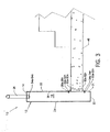
- FIG. 3 illustrates an end view, in cross section, showing the electronic sign enclosure having a rail mounted to a concrete seating deck
- FIG. 4 an alternative embodiment, illustrates an electronic sign enclosure with steel structure and a rail which are mounted by other means to a concrete seating deck.
- FIG. 1 illustrates an isometric rear view of an electronic sign enclosure having a rail 10, the present invention.
- the electronic sign enclosure having a rail 10 comprises an enclosure 12 and a rail 26.
- the enclosure 12 includes a top panel 14, opposing end panels 16 and 18, a bottom panel 20, a rear panel 21, a removable access panel 22 secured over and about and to the rear panel 21, and a removable front panel 24.
- the rail 26 secures to the top panel 14 of the enclosure 12.
- the top panel 14, the opposing end panels 16 and 18, and the bottom panel 20 are of channel stock and may be positionally inverted or reversed, as shown in an alternate embodiment.
- Suitably spaced and opposing pluralities of upper brackets 28a-28n and lower brackets 30a-30n suitably secure, such as by nut and bolt assemblies 32a-32n and 34a-34n, to the lower region of the rear panel 21.
- FIG. 2 illustrates an exploded isometric rear view of the electronic sign enclosure having a rail 10.
- an access cutout 36 which is normally covered by the access panel 22, is revealed.
- Access cutout 36 offers access to electronic components which can be housed in the enclosure 12.
- the front panel 24 is used for the mounting of desired electronic display information which can be viewed from the front of the invention.
- Holes 40 and 42 are included in the top panel 14 for mounting of the threaded ends 44 and 46 of the rail 26.
- the rail 26 is shown as tubular (see FIG. 3 ) and mounting threads are shown for purposes of example and illustration, but each can be of other suitable configuration to provide a rail which is mountable to the enclosure 12.
- FIG. 3 illustrates an end view, in cross section, of the electronic sign enclosure having a rail 10 mounted to a concrete seating deck 48.
- a plurality of upper and lower mounting plates 50a-50n and 52a-52n, respectively, are cast or otherwise secured to the upper and lower surfaces of the concrete seating deck 48.
- the pluralities of upper brackets 28a-28n and lower brackets 30a-30n, which are removable from the enclosure 12, are secured, such as by welding, to the upper and lower mounting plates 50a-50n and 52a-52n, respectively, to firmly secure the electronic enclosure having a rail 10 to the upper and lower surfaces of the concrete seating deck 48.
- the rear panel 21 of the electronic enclosure having a rail 10 firmly abuts the vertical edge of the concrete seating deck 48 to provide for additional stability.
- a plurality of nuts 54a-54n engage the threaded ends of the rail 26 to fasten the rail 26 to the enclosure 12. Such an installation provides for a personnel barrier and rail.
- FIG. 4 an alternative embodiment, illustrates an electronic sign enclosure 12 with steel structure 56 and a rail 58 which are mounted by other means to a concrete seating deck 48.
- This alternative embodiment is substantially the same as the electronic sign enclosure having a rail 10, but in this alternative embodiment the rail 58 is displaced from the enclosure 12 and included on the steel structure 56, and the enclosure 12 has an angled top panel 68.
- a plurality of removable upper brackets 60a-60n and a plurality of removable lower brackets 62a-62n replace the upper brackets 28a-28n and lower brackets 30a-30n, shown in FIG. 1, and are welded to the steel structure 56 and are incorporated to secure the enclosure 12 to the steel structure 56 using a plurality of nut and bolt assemblies 64a-64n and 66a-66n.
- the top panel 14 and the bottom panel 20 are inverted.
- the angled top panel 68 bridges the region between the upper areas of the front panel 24 and the rear panel 21.
- An anti-vandal panel 70 can also be attached to the
Landscapes
- Physics & Mathematics (AREA)
- General Physics & Mathematics (AREA)
- Engineering & Computer Science (AREA)
- Theoretical Computer Science (AREA)
- Business, Economics & Management (AREA)
- Accounting & Taxation (AREA)
- Marketing (AREA)
- Devices For Indicating Variable Information By Combining Individual Elements (AREA)
- Road Signs Or Road Markings (AREA)
- Structure Of Receivers (AREA)
- Shielding Devices Or Components To Electric Or Magnetic Fields (AREA)
- Casings For Electric Apparatus (AREA)
Abstract
Description
- 10
- electronic sign enclosure having a rail
- 12
- enclosure
- 14
- top panel
- 16
- end panel
- 18
- end panel
- 20
- bottom panel
- 21
- rear panel
- 22
- access panel
- 24
- front panel
- 26
- rail
- 28a-n
- upper brackets
- 30a-n
- lower brackets
- 32a-n
- nut and bolt assemblies
- 34a-n
- nut and bolt assemblies
- 36
- access cutout
- 40
- hole
- 42
- hole
- 44
- threaded end
- 46
- threaded end
- 48
- concrete seating deck
- 50a-n
- mounting plates
- 52a-n
- mounting plates
- 54a-n
- nuts
- 56
- steel structure
- 58
- rail
- 60a-n
- upper brackets
- 62a-n
- lower brackets
- 64a-n
- nut and bolt assemblies
- 66a-n
- nut and bolt assemblies
- 68
- angled top panel
- 70
- anti-vandal panel
Claims (18)
- In combination, an edge of a structural member (48) and electronic sign (10) comprising:a. a structural edge (48); andb. an electronic sign (10) including spaced opposing upper (28) and lower (30) brackets on a lower rear panel (21) of said sign, an access panel (22) on an upper rear panel of said sign, and a rail means (26) on a top of said sign.
- An electronic sign enclosure (10) having a rail (26) which can be secured to the edge of a seating deck or balcony and acts as a barrier, comprising:a. an edge of a deck (48); andb. a rail (26) located along and about an upper surface (14) including a series of upper (28a - 28n) and lower (30a - 30n) brackets located along a rearwardly facing enclosure surface (21), each of which secures to metal mounting plates (50a - 50n, 52a - 52n) on the upper and lower surfaces at said edge of the seating deck (48), whereby the electronic sign enclosure having the rail is of sufficient height to prevent people from accidentally falling over the edge of the seating deck (48) and serves as a safety barrier, which can be accessed by maintenance personnel without the interference or hindrance of a traditional seating deck barrier structure.
- A sign assembly (10) which comprises:(a) an enclosure, frame or other housing (12) for a sign, the enclosure having front and rear faces, the front face (24) to accommodate a sign and the rear face (21) having access means (36) to permit access to the sign;(b) handhold means (26) attached directly or indirectly to the housing (12); and(c) securement means (28a - 28n, 30a - 30n) suitable for securement of the sign assembly to a deck, floor, platform, balcony, ledge or other spectator support member (48).
- A sign assembly according to Claim 3, wherein the sign is an electronic sign.
- A sign assembly according to Claim 3 or 4, wherein the handhold means (26) is a rail.
- A sign assembly according to Claim 5, wherein the rail extends substantially parallel to the top of housing (12).
- A sign assembly according to Claim 3, wherein the housing (12) is an electronic sign enclosure including a top panel (14), opposing end panels (16, 18), bottom panel (20), rear panel (21) and a removable access panel (22) secured over rear panel (21) and a removable front panel (24).
- A sign assembly according to Claim 7, wherein top panel (14), opposing end panels (16, 18) and bottom panel (20) are of steel channel stock.
- A sign assembly according to Claim 3, wherein said securement means comprises suitably spaced and opposed pluralities of upper brackets (28a - 28n) and lower brackets (30a - 30n) suitably secured to the lower region of rear panel (21).
- A sign assembly according to Claim 3, wherein the housing (12) is secured to a support (56) suitable for securement of the sign assembly to a deck, floor, platform, balcony, ledge or other spectator support member (48); and
the handhold means (26) is secured to support (56). - A sign assembly according to Claim 10, wherein the support (56) is disposed substantially parallel to rear face (21) of housing (12).
- A sign assembly according to Claim 10 to 11, wherein the handhold means (26) is secured to support (56) but not to housing (12).
- A sign assembly according to Claim 10, 11 or 12, wherein housing (12) is secured to support (56) by securement means (60a - 60n, 62a - 62n) attached to the rear face (21) of the housing.
- A sign assembly according to any of Claims 10 to 13, wherein the support (56) comprises a framework and said securement means comprises upper and lower brackets, the upper brackets (60a - 60n) being secured to an upper region of rear face (21) and the lower brackets (62a - 62n) being secured to a lower region of rear face (21).
- A sign assembly according to any of Claims 10 to 14, wherein the spectator support member is a concrete seating deck.
- A sign assembly according to any of the preceding claims in combination with a spectator support structure (48), the sign assembly being secured to an edge of the spectator support structure, thereby to act as a safety barrier to guard against spectators falling from said structure (48).
- A sign assembly according to Claim 16, which abuts said edge of the spectator support structure to provide additional stability for the sign assembly.
- A sign assembly according to Claim 16 or 17, wherein the spectator support structure (48) has, secured to the region of said edge thereof, a plurality of connector plates secured to said securement means (28a - 28n, 30a - 30n).
Applications Claiming Priority (2)
| Application Number | Priority Date | Filing Date | Title |
|---|---|---|---|
| US943043 | 1992-09-10 | ||
| US09/943,043 US6851210B1 (en) | 2001-08-29 | 2001-08-29 | Electronic sign enclosure having a rail |
Publications (3)
| Publication Number | Publication Date |
|---|---|
| EP1288889A2 true EP1288889A2 (en) | 2003-03-05 |
| EP1288889A3 EP1288889A3 (en) | 2006-06-07 |
| EP1288889B1 EP1288889B1 (en) | 2010-10-13 |
Family
ID=25479009
Family Applications (1)
| Application Number | Title | Priority Date | Filing Date |
|---|---|---|---|
| EP02255867A Expired - Lifetime EP1288889B1 (en) | 2001-08-29 | 2002-08-22 | Electronic sign enclosure having a rail |
Country Status (4)
| Country | Link |
|---|---|
| US (1) | US6851210B1 (en) |
| EP (1) | EP1288889B1 (en) |
| AT (1) | ATE484814T1 (en) |
| DE (1) | DE60237947D1 (en) |
Families Citing this family (1)
| Publication number | Priority date | Publication date | Assignee | Title |
|---|---|---|---|---|
| JP7582659B2 (en) | 2021-01-19 | 2024-11-13 | 株式会社美貴本 | Advertising display device |
Family Cites Families (22)
| Publication number | Priority date | Publication date | Assignee | Title |
|---|---|---|---|---|
| US819338A (en) * | 1905-11-27 | 1906-05-01 | Arthur P Claridge | Sign-support. |
| US2765554A (en) * | 1953-01-14 | 1956-10-09 | Union Metal Mfg Co | Highway sign support |
| US2867306A (en) * | 1955-10-14 | 1959-01-06 | Theodore M Lasinski | Luggage handle |
| US3863900A (en) * | 1973-04-13 | 1975-02-04 | Symons Corp | Removable guard rail assembly and stanchion bracket therefor |
| US3863899A (en) * | 1973-08-27 | 1975-02-04 | Richard W Werner | Removable guard rail |
| US3995833A (en) * | 1975-07-23 | 1976-12-07 | Jack McLaughlin | Removable guard rail stanchion apparatus |
| US3988845A (en) * | 1975-08-07 | 1976-11-02 | Sedalia Neon Company | Sign device having magnetic display characters |
| US4263736A (en) * | 1978-10-11 | 1981-04-28 | Colorado Time Systems, Inc. | Modular display system |
| US4669577A (en) * | 1986-07-21 | 1987-06-02 | Saf-T-Green Manufacturing Corporation | Slab clamp guard rail post |
| US4937499A (en) * | 1986-09-22 | 1990-06-26 | Hunte Herbert H | Photosensitive illuminating display |
| WO1990000657A1 (en) * | 1988-07-11 | 1990-01-25 | Cornelis Johannes Griek | A stanchion assembly |
| US4970816A (en) * | 1990-01-11 | 1990-11-20 | Everbrite Electric Signs, Inc. | Roof sign |
| US5259089A (en) * | 1992-03-02 | 1993-11-09 | Phc Industries, Inc. | Handle |
| US5497573A (en) * | 1994-04-14 | 1996-03-12 | Stadjuhar; Robert C. | Thermally-protected display with a ventilation system |
| US5522540A (en) * | 1994-04-21 | 1996-06-04 | Surman; Robert L. | Solar powered illuminated address number device and mailbox structure |
| US5566926A (en) * | 1994-08-19 | 1996-10-22 | Voight Products Incorporated | Resilient safety barrier |
| US5685511A (en) * | 1995-12-06 | 1997-11-11 | Ghany; Mitchell F. | Banner mount |
| US5803420A (en) * | 1996-03-13 | 1998-09-08 | Cormark, Inc. | Universal sign mounting device |
| US5924367A (en) * | 1997-04-10 | 1999-07-20 | Rtc Industries, Inc. | Shelf sign system |
| US6015124A (en) * | 1997-09-18 | 2000-01-18 | Darko Company, Inc. | Bracket assembly for carrying signage for a retail display fixture |
| US6314669B1 (en) * | 1999-02-09 | 2001-11-13 | Daktronics, Inc. | Sectional display system |
| US6347468B1 (en) * | 1999-11-04 | 2002-02-19 | Abdulahi Mohamed | Portable illuminated sign with changeable messages |
-
2001
- 2001-08-29 US US09/943,043 patent/US6851210B1/en not_active Expired - Lifetime
-
2002
- 2002-08-22 EP EP02255867A patent/EP1288889B1/en not_active Expired - Lifetime
- 2002-08-22 AT AT02255867T patent/ATE484814T1/en not_active IP Right Cessation
- 2002-08-22 DE DE60237947T patent/DE60237947D1/en not_active Expired - Lifetime
Also Published As
| Publication number | Publication date |
|---|---|
| ATE484814T1 (en) | 2010-10-15 |
| EP1288889A3 (en) | 2006-06-07 |
| US6851210B1 (en) | 2005-02-08 |
| DE60237947D1 (en) | 2010-11-25 |
| EP1288889B1 (en) | 2010-10-13 |
Similar Documents
| Publication | Publication Date | Title |
|---|---|---|
| CA1255733A (en) | Beam-type work station system | |
| US5383723A (en) | Earthquake resistant electronic equipment frame | |
| US6964410B1 (en) | Suspended glass panel railing system | |
| US6681942B2 (en) | Rack mount assembly | |
| US20210381271A1 (en) | System and method for vertical and horizontal in-fill installation | |
| US7866075B2 (en) | Button capture sign system | |
| KR101991294B1 (en) | Assembly type fence having horizontal leveling device | |
| US4899892A (en) | Earthquake-resistant electronic equipment frame | |
| US9097025B2 (en) | Panel support post | |
| JPH10246282A (en) | Earthquake resistant apparatus platform, manufacture thereof, and device for resisting earthquake | |
| GB2407494A (en) | Supporting spine structure for modular office furniture | |
| US20200362566A1 (en) | Fascia Mounted Railing System | |
| US7222467B2 (en) | Screen with integral railing | |
| EP1288889A2 (en) | Electronic sign enclosure having a rail | |
| CA3146615A1 (en) | Brackets for stair railings | |
| US11821574B1 (en) | Panel mount base | |
| CN217933071U (en) | LED display module and LED display device with same | |
| GB2225800A (en) | Portable barrier | |
| CN111564127B (en) | Multifunctional propaganda column | |
| US20040216390A1 (en) | Facade vending machines | |
| JP3254869U (en) | Anti-fall fittings | |
| CN222228121U (en) | A movable outdoor inclined stage | |
| JPH09324521A (en) | Free access floor | |
| EP1467571B1 (en) | Device for integrating of monitors in monitoring structures | |
| CA2695046C (en) | Panel support post |
Legal Events
| Date | Code | Title | Description |
|---|---|---|---|
| PUAI | Public reference made under article 153(3) epc to a published international application that has entered the european phase |
Free format text: ORIGINAL CODE: 0009012 |
|
| AK | Designated contracting states |
Kind code of ref document: A2 Designated state(s): AT BE BG CH CY CZ DE DK EE ES FI FR GB GR IE IT LI LU MC NL PT SE SK TR |
|
| AX | Request for extension of the european patent |
Extension state: AL LT LV MK RO SI |
|
| PUAL | Search report despatched |
Free format text: ORIGINAL CODE: 0009013 |
|
| AK | Designated contracting states |
Kind code of ref document: A3 Designated state(s): AT BE BG CH CY CZ DE DK EE ES FI FR GB GR IE IT LI LU MC NL PT SE SK TR |
|
| AX | Request for extension of the european patent |
Extension state: AL LT LV MK RO SI |
|
| RIC1 | Information provided on ipc code assigned before grant |
Ipc: G09F 9/30 20060101ALI20060420BHEP Ipc: G09F 19/22 20060101ALI20060420BHEP Ipc: G09F 15/00 20060101AFI20021213BHEP |
|
| 17P | Request for examination filed |
Effective date: 20061207 |
|
| AKX | Designation fees paid |
Designated state(s): AT BE BG CH CY CZ DE DK EE ES FI FR GB GR IE IT LI LU MC NL PT SE SK TR |
|
| GRAP | Despatch of communication of intention to grant a patent |
Free format text: ORIGINAL CODE: EPIDOSNIGR1 |
|
| GRAS | Grant fee paid |
Free format text: ORIGINAL CODE: EPIDOSNIGR3 |
|
| GRAA | (expected) grant |
Free format text: ORIGINAL CODE: 0009210 |
|
| AK | Designated contracting states |
Kind code of ref document: B1 Designated state(s): AT BE BG CH CY CZ DE DK EE ES FI FR GB GR IE IT LI LU MC NL PT SE SK TR |
|
| REG | Reference to a national code |
Ref country code: GB Ref legal event code: FG4D |
|
| REG | Reference to a national code |
Ref country code: CH Ref legal event code: EP |
|
| REG | Reference to a national code |
Ref country code: IE Ref legal event code: FG4D |
|
| REF | Corresponds to: |
Ref document number: 60237947 Country of ref document: DE Date of ref document: 20101125 Kind code of ref document: P |
|
| REG | Reference to a national code |
Ref country code: NL Ref legal event code: VDEP Effective date: 20101013 |
|
| PG25 | Lapsed in a contracting state [announced via postgrant information from national office to epo] |
Ref country code: PT Free format text: LAPSE BECAUSE OF FAILURE TO SUBMIT A TRANSLATION OF THE DESCRIPTION OR TO PAY THE FEE WITHIN THE PRESCRIBED TIME-LIMIT Effective date: 20110214 Ref country code: AT Free format text: LAPSE BECAUSE OF FAILURE TO SUBMIT A TRANSLATION OF THE DESCRIPTION OR TO PAY THE FEE WITHIN THE PRESCRIBED TIME-LIMIT Effective date: 20101013 Ref country code: BG Free format text: LAPSE BECAUSE OF FAILURE TO SUBMIT A TRANSLATION OF THE DESCRIPTION OR TO PAY THE FEE WITHIN THE PRESCRIBED TIME-LIMIT Effective date: 20110113 Ref country code: FI Free format text: LAPSE BECAUSE OF FAILURE TO SUBMIT A TRANSLATION OF THE DESCRIPTION OR TO PAY THE FEE WITHIN THE PRESCRIBED TIME-LIMIT Effective date: 20101013 Ref country code: SE Free format text: LAPSE BECAUSE OF FAILURE TO SUBMIT A TRANSLATION OF THE DESCRIPTION OR TO PAY THE FEE WITHIN THE PRESCRIBED TIME-LIMIT Effective date: 20101013 Ref country code: NL Free format text: LAPSE BECAUSE OF FAILURE TO SUBMIT A TRANSLATION OF THE DESCRIPTION OR TO PAY THE FEE WITHIN THE PRESCRIBED TIME-LIMIT Effective date: 20101013 |
|
| PG25 | Lapsed in a contracting state [announced via postgrant information from national office to epo] |
Ref country code: BE Free format text: LAPSE BECAUSE OF FAILURE TO SUBMIT A TRANSLATION OF THE DESCRIPTION OR TO PAY THE FEE WITHIN THE PRESCRIBED TIME-LIMIT Effective date: 20101013 Ref country code: GR Free format text: LAPSE BECAUSE OF FAILURE TO SUBMIT A TRANSLATION OF THE DESCRIPTION OR TO PAY THE FEE WITHIN THE PRESCRIBED TIME-LIMIT Effective date: 20110114 |
|
| PG25 | Lapsed in a contracting state [announced via postgrant information from national office to epo] |
Ref country code: EE Free format text: LAPSE BECAUSE OF FAILURE TO SUBMIT A TRANSLATION OF THE DESCRIPTION OR TO PAY THE FEE WITHIN THE PRESCRIBED TIME-LIMIT Effective date: 20101013 Ref country code: ES Free format text: LAPSE BECAUSE OF FAILURE TO SUBMIT A TRANSLATION OF THE DESCRIPTION OR TO PAY THE FEE WITHIN THE PRESCRIBED TIME-LIMIT Effective date: 20110124 Ref country code: CZ Free format text: LAPSE BECAUSE OF FAILURE TO SUBMIT A TRANSLATION OF THE DESCRIPTION OR TO PAY THE FEE WITHIN THE PRESCRIBED TIME-LIMIT Effective date: 20101013 |
|
| PLBE | No opposition filed within time limit |
Free format text: ORIGINAL CODE: 0009261 |
|
| STAA | Information on the status of an ep patent application or granted ep patent |
Free format text: STATUS: NO OPPOSITION FILED WITHIN TIME LIMIT |
|
| PG25 | Lapsed in a contracting state [announced via postgrant information from national office to epo] |
Ref country code: SK Free format text: LAPSE BECAUSE OF FAILURE TO SUBMIT A TRANSLATION OF THE DESCRIPTION OR TO PAY THE FEE WITHIN THE PRESCRIBED TIME-LIMIT Effective date: 20101013 Ref country code: DK Free format text: LAPSE BECAUSE OF FAILURE TO SUBMIT A TRANSLATION OF THE DESCRIPTION OR TO PAY THE FEE WITHIN THE PRESCRIBED TIME-LIMIT Effective date: 20101013 |
|
| 26N | No opposition filed |
Effective date: 20110714 |
|
| REG | Reference to a national code |
Ref country code: DE Ref legal event code: R097 Ref document number: 60237947 Country of ref document: DE Effective date: 20110714 |
|
| PG25 | Lapsed in a contracting state [announced via postgrant information from national office to epo] |
Ref country code: IT Free format text: LAPSE BECAUSE OF FAILURE TO SUBMIT A TRANSLATION OF THE DESCRIPTION OR TO PAY THE FEE WITHIN THE PRESCRIBED TIME-LIMIT Effective date: 20101013 |
|
| PG25 | Lapsed in a contracting state [announced via postgrant information from national office to epo] |
Ref country code: MC Free format text: LAPSE BECAUSE OF NON-PAYMENT OF DUE FEES Effective date: 20110831 |
|
| REG | Reference to a national code |
Ref country code: CH Ref legal event code: PL |
|
| PG25 | Lapsed in a contracting state [announced via postgrant information from national office to epo] |
Ref country code: CH Free format text: LAPSE BECAUSE OF NON-PAYMENT OF DUE FEES Effective date: 20110831 Ref country code: LI Free format text: LAPSE BECAUSE OF NON-PAYMENT OF DUE FEES Effective date: 20110831 |
|
| REG | Reference to a national code |
Ref country code: FR Ref legal event code: ST Effective date: 20120430 |
|
| REG | Reference to a national code |
Ref country code: IE Ref legal event code: MM4A |
|
| PG25 | Lapsed in a contracting state [announced via postgrant information from national office to epo] |
Ref country code: IE Free format text: LAPSE BECAUSE OF NON-PAYMENT OF DUE FEES Effective date: 20110822 |
|
| PG25 | Lapsed in a contracting state [announced via postgrant information from national office to epo] |
Ref country code: FR Free format text: LAPSE BECAUSE OF NON-PAYMENT OF DUE FEES Effective date: 20110831 |
|
| PG25 | Lapsed in a contracting state [announced via postgrant information from national office to epo] |
Ref country code: LU Free format text: LAPSE BECAUSE OF NON-PAYMENT OF DUE FEES Effective date: 20110822 Ref country code: CY Free format text: LAPSE BECAUSE OF EXPIRATION OF PROTECTION Effective date: 20101013 |
|
| PG25 | Lapsed in a contracting state [announced via postgrant information from national office to epo] |
Ref country code: TR Free format text: LAPSE BECAUSE OF FAILURE TO SUBMIT A TRANSLATION OF THE DESCRIPTION OR TO PAY THE FEE WITHIN THE PRESCRIBED TIME-LIMIT Effective date: 20101013 |
|
| PGFP | Annual fee paid to national office [announced via postgrant information from national office to epo] |
Ref country code: GB Payment date: 20170829 Year of fee payment: 16 Ref country code: DE Payment date: 20170829 Year of fee payment: 16 |
|
| REG | Reference to a national code |
Ref country code: DE Ref legal event code: R119 Ref document number: 60237947 Country of ref document: DE |
|
| GBPC | Gb: european patent ceased through non-payment of renewal fee |
Effective date: 20180822 |
|
| PG25 | Lapsed in a contracting state [announced via postgrant information from national office to epo] |
Ref country code: DE Free format text: LAPSE BECAUSE OF NON-PAYMENT OF DUE FEES Effective date: 20190301 |
|
| PG25 | Lapsed in a contracting state [announced via postgrant information from national office to epo] |
Ref country code: GB Free format text: LAPSE BECAUSE OF NON-PAYMENT OF DUE FEES Effective date: 20180822 |