EP1288537A2 - Dichtring - Google Patents
Dichtring Download PDFInfo
- Publication number
- EP1288537A2 EP1288537A2 EP02008889A EP02008889A EP1288537A2 EP 1288537 A2 EP1288537 A2 EP 1288537A2 EP 02008889 A EP02008889 A EP 02008889A EP 02008889 A EP02008889 A EP 02008889A EP 1288537 A2 EP1288537 A2 EP 1288537A2
- Authority
- EP
- European Patent Office
- Prior art keywords
- sealing
- ring
- sealed
- sealing ring
- support
- Prior art date
- Legal status (The legal status is an assumption and is not a legal conclusion. Google has not performed a legal analysis and makes no representation as to the accuracy of the status listed.)
- Granted
Links
- 238000007789 sealing Methods 0.000 claims abstract description 159
- 239000000463 material Substances 0.000 claims description 22
- 239000011248 coating agent Substances 0.000 claims description 14
- 238000000576 coating method Methods 0.000 claims description 14
- 230000002093 peripheral effect Effects 0.000 claims description 14
- 239000011324 bead Substances 0.000 claims description 13
- 238000004519 manufacturing process Methods 0.000 claims description 13
- 239000004810 polytetrafluoroethylene Substances 0.000 claims description 9
- 229920001343 polytetrafluoroethylene Polymers 0.000 claims description 9
- 239000007769 metal material Substances 0.000 claims description 7
- 239000013536 elastomeric material Substances 0.000 claims description 6
- 150000001875 compounds Chemical class 0.000 claims description 4
- 239000004922 lacquer Substances 0.000 claims description 2
- 229920001971 elastomer Polymers 0.000 abstract description 7
- 239000000806 elastomer Substances 0.000 abstract description 7
- 230000018109 developmental process Effects 0.000 description 4
- 239000004952 Polyamide Substances 0.000 description 2
- 238000001125 extrusion Methods 0.000 description 2
- 238000009434 installation Methods 0.000 description 2
- 238000000034 method Methods 0.000 description 2
- 229920002647 polyamide Polymers 0.000 description 2
- 230000035882 stress Effects 0.000 description 2
- 238000004073 vulcanization Methods 0.000 description 2
- 238000005299 abrasion Methods 0.000 description 1
- 239000000654 additive Substances 0.000 description 1
- 230000002411 adverse Effects 0.000 description 1
- 230000032683 aging Effects 0.000 description 1
- 238000010276 construction Methods 0.000 description 1
- 238000000354 decomposition reaction Methods 0.000 description 1
- 230000007547 defect Effects 0.000 description 1
- 230000000694 effects Effects 0.000 description 1
- 238000005516 engineering process Methods 0.000 description 1
- 230000002349 favourable effect Effects 0.000 description 1
- 239000012208 gear oil Substances 0.000 description 1
- 239000010720 hydraulic oil Substances 0.000 description 1
- 238000005461 lubrication Methods 0.000 description 1
- 230000008092 positive effect Effects 0.000 description 1
- 230000036316 preload Effects 0.000 description 1
- 230000002028 premature Effects 0.000 description 1
- 238000004064 recycling Methods 0.000 description 1
- 230000000717 retained effect Effects 0.000 description 1
- 238000007493 shaping process Methods 0.000 description 1
- 238000005507 spraying Methods 0.000 description 1
- 230000003068 static effect Effects 0.000 description 1
- 230000003746 surface roughness Effects 0.000 description 1
- 229920001169 thermoplastic Polymers 0.000 description 1
- 239000004416 thermosoftening plastic Substances 0.000 description 1
Images





Classifications
-
- F—MECHANICAL ENGINEERING; LIGHTING; HEATING; WEAPONS; BLASTING
- F16—ENGINEERING ELEMENTS AND UNITS; GENERAL MEASURES FOR PRODUCING AND MAINTAINING EFFECTIVE FUNCTIONING OF MACHINES OR INSTALLATIONS; THERMAL INSULATION IN GENERAL
- F16J—PISTONS; CYLINDERS; SEALINGS
- F16J15/00—Sealings
- F16J15/16—Sealings between relatively-moving surfaces
- F16J15/32—Sealings between relatively-moving surfaces with elastic sealings, e.g. O-rings
- F16J15/3204—Sealings between relatively-moving surfaces with elastic sealings, e.g. O-rings with at least one lip
- F16J15/3224—Sealings between relatively-moving surfaces with elastic sealings, e.g. O-rings with at least one lip capable of accommodating changes in distances or misalignment between the surfaces, e.g. able to compensate for defaults of eccentricity or angular deviations
-
- F—MECHANICAL ENGINEERING; LIGHTING; HEATING; WEAPONS; BLASTING
- F16—ENGINEERING ELEMENTS AND UNITS; GENERAL MEASURES FOR PRODUCING AND MAINTAINING EFFECTIVE FUNCTIONING OF MACHINES OR INSTALLATIONS; THERMAL INSULATION IN GENERAL
- F16J—PISTONS; CYLINDERS; SEALINGS
- F16J15/00—Sealings
- F16J15/16—Sealings between relatively-moving surfaces
- F16J15/32—Sealings between relatively-moving surfaces with elastic sealings, e.g. O-rings
- F16J15/3204—Sealings between relatively-moving surfaces with elastic sealings, e.g. O-rings with at least one lip
- F16J15/3216—Sealings between relatively-moving surfaces with elastic sealings, e.g. O-rings with at least one lip supported in a direction parallel to the surfaces
-
- F—MECHANICAL ENGINEERING; LIGHTING; HEATING; WEAPONS; BLASTING
- F16—ENGINEERING ELEMENTS AND UNITS; GENERAL MEASURES FOR PRODUCING AND MAINTAINING EFFECTIVE FUNCTIONING OF MACHINES OR INSTALLATIONS; THERMAL INSULATION IN GENERAL
- F16J—PISTONS; CYLINDERS; SEALINGS
- F16J15/00—Sealings
- F16J15/16—Sealings between relatively-moving surfaces
- F16J15/32—Sealings between relatively-moving surfaces with elastic sealings, e.g. O-rings
- F16J15/3204—Sealings between relatively-moving surfaces with elastic sealings, e.g. O-rings with at least one lip
- F16J15/322—Sealings between relatively-moving surfaces with elastic sealings, e.g. O-rings with at least one lip supported in a direction perpendicular to the surfaces
Definitions
- the invention relates to a sealing ring comprising a sealing collar elastomeric material with at least one sealing lip for sealing a space to be sealed, the sealing sleeve with a stiffening ring is made of tough hard material.
- Such sealing rings are generally known and are used, for example, as Radial shaft seals for use.
- the sealing sleeve and the Stiffening ring are vulcanized together, the sealing collar is flexible in the radial direction in the area of the sealing lip.
- Radial shaft seals with an axially short sealing sleeve for sealing pressurized media is the comparatively low flexibility / large Stiffness unsatisfactory for many applications, for example Unbalance of the machine element to be sealed and / or operational Wear of the sealing lip is insufficiently compensated for by the sealing ring can be.
- the previously known sealing rings with a comparatively large radial The known sealing rings with a comparatively large size are lacking radial overlap installed, i.e. the sealing lip has to do with production a significantly smaller diameter than the surface of the one to be sealed Machine element.
- such a large radial coverage leads to a high friction torque during operation and an undesirable premature wear of the sealing lip.
- the invention has for its object a sealing ring of the beginning mentioned type to develop in such a way that this improved performance during an extended period of use.
- the frictional torque between the sealing collar and the machine element to be sealed can be reduced.
- Eccentricities and / or The machine element to be sealed should be unbalanced by a increased freedom of movement of the sealing lip better balanced become.
- the sealing ring is said to be more economical and more technical Regarding be easier and cheaper to manufacture.
- the sealing sleeve in Considered longitudinal section of the sealing ring, essentially C-shaped and is open axially in the direction of the space to be sealed, with a radial outer and a radially inner axial leg, the axial leg on the side axially facing away from the space to be sealed by a radial arm are connected that the outer axial leg only on the sealing space axially facing side with the stiffening ring is connected and that the outer peripheral surface of the outer axial leg and the end face of the radial arm that faces axially away from the space to be sealed are assigned to a support ring without liability.
- the sealing lip related to sealing rings, where the sealing lip arranged in the immediate vicinity of the stiffening ring and by vulcanization associated with this, a comparatively large freedom of movement, especially in the radial direction in order to eccentricities of the sealing To be able to compensate for machine elements and / or imbalances. Moreover is due to the unrelated assignment of the outer axial leg and the Radial leg to the support ring and the resulting larger Freedom of movement the frictional torque between the sealing lip and the machine element to be sealed reduces what in terms of good Performance characteristics during a very long service life of advantage to be emphasized; the abrasive wear of the sealing lip on the previously described sealing ring from the prior art is essential reduced. Due to these advantageous properties, the Sealing ring according to the invention particularly well suited, even higher pressures seal. If the sealing ring is used, for example, as a pump seal Application, for example, pump pressures of up to 150 bar can be easily sealed.
- the low heat transfer to the medium to be sealed has a positive effect on the aging of the medium to be sealed and / or Decomposition of the additives contained in the medium to be sealed.
- the outer peripheral surface and the end face of the support ring with each Distance adjacent assigned can be applied to this.
- Such one Design is therefore preferred within the scope of the present invention given because a sealing ring designed in this way is the first one Solves task particularly well.
- the outer peripheral area that one Axial flange of the support ring is assigned adjacent with a radial distance, wherein the radial distance forms the radial spring travel of the sealing lip the advantageous usage properties because of the excellent flexibility the frictional lip in the radial direction and the resulting torque the heat development is significantly reduced and the sealing lip Eccentricities and / or unbalances of the machine element to be sealed is particularly good at following.
- the outer peripheral surface touches the support ring and that only the face of the Support ring is spaced adjacent and can be applied to this.
- Sealing ring which is designed in this way, has compared to conventional Sealing rings due to the unbound assignment of the outer axial leg to the axial flange of the support ring more favorable usage properties because the flexibility of the sealing lip in the radial direction is still higher than if the sealing lip arranged in the immediate vicinity of the stiffening ring and with this is vulcanized, but the flexibility of the sealing lip is radial Direction limited, compared to the first embodiment, the previous one has been described.
- the outer circumferential surface of the sealing ring can be in contact with the support ring touch.
- the stiffening ring and the support ring can each be produced separately and be positively and / or positively connected.
- the material of the stiffening ring and the material of the support ring the particular circumstances of the application are particularly good can be customized.
- the support ring can be made of a polymeric material exist, e.g. made of a PTFE compound and with its axial flange be pressed into the stiffening ring.
- Such a support ring would have that Advantage that even with high pressure on the sealing ring and / or large eccentricities and / or unbalances of the to be sealed Machine element a perfect relative mobility of the sealing sleeve based on the support ring made of friction-reducing material would be preserved.
- the stiffening ring can also be axially attached to it extending inner surface to be coated with elastomer. This has the advantage that larger radial tolerances of both the stiffening and the support ring are acceptable and the rings can thus be manufactured more cost-effectively.
- Back-up rings made of polymeric material also show in comparison to designed support rings made of metallic materials, a comparatively lower mass, which for some applications of Advantage is.
- the stiffening ring and the support ring integrally merging into one another and using the same material are trained.
- the advantage here is that the assembly of the sealing ring is simplified by such a configuration, as well as that Recycling after replacing the sealing ring, for example because of operational wear.
- the inner axial leg can be radially on the outside by a coil spring be enclosed to increase the contact pressure of the sealing lip on the Surface of the machine element to be sealed.
- the coil spring apply.
- a coil spring advantageous because the low pressure within the space to be sealed is not always sufficient, a sealing pressure of the sealing lip on the surface of the machine element to be sealed, even with high dynamic shaft eccentricity and high shaft speed.
- the outer axial leg and / or the radial leg and / or the support ring preferably have a friction-reducing on the facing sides Surface coating on.
- the surface coating can for example, be formed by a PTFE film or by a lacquer.
- the friction-reducing surface coating means that Sealing collar and the support ring can also be moved relative to one another, if pressure changes occur within the space to be sealed and / or the sealing sleeve eccentricities and / or unbalances of the sealing Machine element must compensate. If the support ring does not exist made of a friction-reducing material, for example a PTFE compound or a thermoplastic, but from a metallic material, From a manufacturing point of view, it is easier to reduce friction Apply surface coating to the support ring than on the elastomeric material of the sealing sleeve.
- a friction-reducing material for example a PTFE compound or a thermoplastic
- the coating of the support ring also has the advantage that surface roughness of the support ring has no influence on the adhesion of the sealing collar to have.
- a surface coating for the sealing sleeve is advantageous, for example, that of a PTFE film already inserted in the shaping tool of the sealing sleeve and at Forming process can be vulcanized.
- the sealing lip can be cut by two intersecting conical surfaces be formed, the first cone angle being that of the space to be sealed facing away from the first conical surface with the axis of the machine element to be sealed limited, at most 10 ° smaller than the second cone angle, the second arranged axially in the direction of the space to be sealed Includes conical surface with the axis. In essence, they are two Cone angle about the same size.
- Such a configuration is advantageous to to ensure good lubrication of the sealing lip.
- the operational one Wear on the sealing lip is reduced to a minimum. Besides, is advantageous that this keeps the length of the inner axial leg short and thus the pressure generated by the pressure to be sealed Sealing sleeve on the shaft can be kept small.
- the support ring is preferably designed as an angle ring and has a radial and an axial flange, which acts as an abutment for the radial arm and the serve radially outer axial leg of the sealing sleeve.
- the first conical surface can be axial on the radial flange of the support ring facing side have a support bead, the ratio of Length of the first conical surface to the length of the second conical surface 0.3 to 0.8 is.
- the support bead is particularly in connection with a conical surface sensible that a comparatively large first cone angle with the axis of the machine element to be sealed and / or to be sealed Pressures that exceed 3 bar, for example.
- the sealing sleeve When pressurized the sealing sleeve puts the support bead on the one to be sealed Room facing side of the support surface and thereby prevents the sealing lip folds over and the one facing the space to be sealed second conical surface even on the surface of the machine element to be sealed creates and thereby the performance characteristics of the sealing ring negatively impacted to a significant extent.
- the compared to the second conical surface shorter first cone surface provided with the support bead prevented folding the sealing lip.
- the support bead can merge in one piece and consist of the same material be formed with the sealing sleeve.
- This simple design the sealing ring has a simple and low-parts construction and is simple and inexpensive to manufacture.
- the support bead can be separated by a generated back-up ring formed, the non-positively and / or positively with the sealing sleeve is connected.
- the back-up ring can be made, for example a PTFE compound.
- the back-up ring is preferably unbound snapped into an undercut of the first conical surface, i.e. form-fitting connected. Deviating from this, however, there is also the possibility that the back-up ring is only non-positively connected to the sealing sleeve is or is associated with this bound.
- the back-up ring prevents one Extrusion of the elastomer material of the sealing lip from the space to be sealed with comparatively higher pressure towards the environment with comparatively lower pressure.
- the radial height of the back-up ring covers in radial direction the radially inner end of the radial flange of the Support ring and is the surface of the machine element to be sealed except for one during the intended use of the sealing ring small radial distance adjacent.
- the sealing lip can in the production-related state of the sealing ring with the Surface of the machine element to be sealed, in the longitudinal half cut considered of the sealing ring, have an overlap that is smaller than the radial spring travel of the outer one corresponding to the radial distance Axial leg between the outer peripheral surface and the radially outer adjacent adjacent axial flange of the support ring.
- Such parameters are advantageous to always have a spring travel of the sealing lip in the radial direction ensure even when the sealing ring is installed.
- the support ring can form part of a housing closure cover. Such a configuration further simplifies the sealing ring; In contrast, is the manufacture of the housing cover by its more complicated shape in terms of manufacturing technology more complex and thereby more expensive.
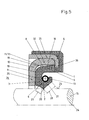
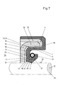
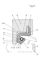
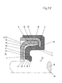
- each of the sealing rings a sealing sleeve 1 made of elastomer Includes material with a sealing lip 2.
- the sealing rings are in production-related Uninstalled state shown, the one to be sealed Machine element 15 designed as a shaft and in two-dot-dash Representation is shown.
- the space 3 to be sealed is sealed in that the sealing lip 2, the surface 14 of the machine element to be sealed 15 seals with radial preload. Within the sealed room 3 prevails over the environment 34 of the comparatively higher pressure.
- the sealing sleeve 1 is made of a tough, hard material Stiffening ring 4 connected in the embodiments shown here is each formed as a deep-drawn angle ring and made of metallic Material exists.
- the sealing sleeve 1 is, viewed in longitudinal section of the sealing ring, in Essentially C-shaped and axially in the direction of the one to be sealed Room 3 open.
- the sealing sleeve includes a radially outer axial leg 5 and a radially inner axial leg 6, the two axial legs 5, 6 on the side facing away from the space 3 to be sealed the radial leg 7 are connected. It’s vitally important that the outer axial leg 5 only on the space to be sealed 3 axially facing side is connected to the stiffening ring 4 and that the outer peripheral surface 8 of the outer axial leg 5 and the one to be sealed Room 3 axially facing end face 9 of the radial leg 7 the Support ring 10 are each assigned without liability.
- the sealing lip 2 is particularly flexible in the radial direction Eccentricities and / or unbalances of the machine element to be sealed 15 balance. In addition, the frictional torque is such Design reduced. The heat development in the area of the sealing lip 2 is thereby limited to a minimum.
- FIG 2 an embodiment is shown, which differs in this regard is designed.
- the outer circumferential surface 8 is in contact with the support ring 10 and only the end face 9 is assigned adjacent to the support ring 10 at a distance 12 and attachable to it.
- the Stiffening ring made of a deep-drawn metallic material, with a Axial projection 35 and a radial projection 36, the sealing sleeve 1 is guided around the radial projection 36 and the axial projection 35 radially on the outside at least partially covered. As a result a static seal against the installation space of the sealing ring.
- the support ring 10 is with its axial flange 32 in the axial projection 35 Stiffening ring 4 pressed in and thus held securely in position.
- FIG. 1 A first exemplary embodiment is shown in FIG.
- the support ring 10 is on its the axial leg 5 and the radial leg 7 of the sealing sleeve 1 facing side 18 provided with a surface coating 19, the is formed by a PTFE film.
- the surface coating 19 prevents adherence of the elastomeric material of the sealing sleeve 1 when the pressure is released, so that the sealing lip 2 is able to its joint-like To spring connection on the radial projection 36.
- FIG 2 a second embodiment of the sealing ring is shown, the differs from the other exemplary embodiments in that the Outer peripheral surface 8 touches the support ring directly.
- the Radial leg 7 is the radial flange 25 on the space to be sealed 3 facing side with an axial distance adjacent. When pressurized the radial arm 7 is supported on the radial flange 25.
- FIG. 3 shows a third exemplary embodiment in which a support ring 10 made of polymeric material is used.
- the support ring 10 is made made of a low-friction polyamide and can be manufactured in a spraying process.
- the polymeric material as material for the Support ring 10 can be realized if necessary complicated geometries. Thereby, that the support ring 10 consists of a low-friction polyamide is Apply a separately created, friction-reducing surface coating dispensable.
- FIG. 4 shows a fourth exemplary embodiment of a sealing ring in which the stiffening ring 4 and the support ring 10 merging into one another and are made of the same material.
- the one to be sealed Room 3 facing side provided a further support ring 37, the has the task of tilting the sealing lip 2 at too high pressure and prevent improper installation.
- improper assembly understood in this context when the machine element to be sealed 15 in this embodiment from the left into the sealing ring is introduced; the correct assembly would, as in the other embodiments also, done from the right.
- FIG. 5 An exemplary embodiment is shown in FIG. 5, similar to the exemplary embodiment from Figure 3, wherein the support ring 10 made of a metallic material consists.
- FIG. 1 A sixth exemplary embodiment is shown in FIG.
- a support bead 26 in Form of a back-up ring 29 is provided, which prevents the elastomer Material from which the sealing lip 2 is made at higher pressures within of the space to be sealed, extruded into the sealing gap.
- Also has the back-up ring has the additional task of preventing the seal from wearing out protect and fold the sealing lip 2 in such a way that the one to be sealed Room 3 facing second conical surface 21 on the surface 14 of the machine element 15 to be sealed, to prevent.
- FIG. 10 A seventh exemplary embodiment of the sealing ring is shown in FIG.
- the radial distance 11 between the outer peripheral surface 8 of the radially outer Axial leg 5 and the axial flange 32 of the support ring 10 is in axial Considered direction, constant.
- the tools needed to manufacture the sealing ring be simple to manufacture and therefore inexpensive.
- FIG. An eighth exemplary embodiment of the sealing ring is shown in FIG. in the In contrast to the exemplary embodiment from FIG. 7, the radial distance is 11 not along the axial extent of the radially outer axial leg constant, but takes in the axial direction from the radial leg 7 in Viewed in the direction of the radial projection 36, continuously as in almost all other embodiments too.
- the outer circumferential surface 8 gradually sets as viewed in the axial direction to the axial flange 32 of the support ring 10. Local stress concentrations are avoided.
- the sides 16, 17 are the radially outer Leg 5 and the radial leg 7 with an integral, provided a friction-reducing surface coating, whereby the surface coating is designed as a PTFE film.
- FIGS. 9 and 10 each show an exemplary embodiment which is shown in FIG Essentially corresponds to the exemplary embodiment from FIG. 6, the as Support bead 26 used back-up rings 29 different are designed.
- the back-up ring 29 is rectangular and prevents an Extrude the sealing lip 2 into the sealing gap and tilt the sealing lip towards the surroundings 34.
- the rectangular geometry of the back-up ring 29 can be produced inexpensively and reliably.
- the back-up ring 29 is wedge-shaped and also exists made of a polymeric material with good abrasion and strength properties having.
- the back-up ring 29 encloses even small ones Operating press the surface 14 of the machine element 15 to be sealed with a radial distance, which means that the overall frictional torque is very low, just like the heat development resulting from the friction. At higher System pressure within the space to be sealed also prevents this Back-up ring 29 the extrusion of elastomeric material of the sealing sleeve 1 towards the surroundings.
- FIG. 11 shows an eleventh embodiment in which the support ring 10 forms part of a housing closure cover 33.
- FIG 12 an embodiment of a sealing ring is shown, similar to that Embodiments described above, but no coil spring 13 is used.
- This variant has the advantage that the Seal produces lower radial forces in depressurized operation since the initial Contact force only by covering the sealing lip 2 with the surface 14 of the machine element 15 to be sealed comes about. Overall, the sealing lip has less wear and tear improved efficiency.
- the first cone angle 22 appears in all the exemplary embodiments shown and the second cone angle 23 is essentially the same size.
- the sealing lip 2 is in each of the embodiments by two intersecting Conical surfaces 20, 21 are formed, the first cone angle 22, which the first conical surface 20 to be sealed with the axis 24 of the machine element 15 to be sealed is limited, at most 10% smaller than the second cone angle 23, which is to be sealed axially in the direction of the Room 3 arranged second conical surface 21 includes the axis 24.
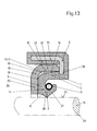
- FIG. 13 shows an exemplary embodiment in which the axial projection 35 is covered on the inside with elastomer 37. This has the advantage that larger radial tolerances of both the stiffening ring 4 and the Support ring 10 are without adverse effects, the rings 4, 10 are cheaper to manufacture.
- the sealing lip 2 has a manufacturing-related Condition of the sealing ring with the surface 14 of the seal Machine element 15, in the longitudinal half-section of the sealing ring considered, an overlap 30 that is smaller than that of the radial Distance 11 corresponding radial spring travel 31 of the outer axial leg 5 between the outer peripheral surface 8 and the radially adjacent adjacent axial flange 32 of the support ring 10.
Landscapes
- Engineering & Computer Science (AREA)
- General Engineering & Computer Science (AREA)
- Mechanical Engineering (AREA)
- Sealing With Elastic Sealing Lips (AREA)
Abstract
Description
Claims (20)
- Dichtring, umfassend eine Dichtmanschette aus elastomerem Werkstoff mit zumindest einer Dichtlippe zur Abdichtung eines abzudichtenden Raums, wobei die Dichtmanschette mit einem Versteifungsring aus zähhartem Werkstoff verbunden ist, dadurch gekennzeichnet, dass die Dichtmanschette (1), im Längsschnitt des Dichtrings betrachtet, im Wesentlichen C-förmig ausgebildet und axial in Richtung des abzudichtenden Raums (3) offen ist, mit einem radial äußeren (5) und einem radial inneren Axialschenkel (6), wobei die Axialschenkel (5, 6) auf der dem abzudichtenden Raum (3) axial abgewandten Seite durch einen Radialschenkel (7) verbunden sind, dass der äußere Axialschenkel (5) nur auf der dem abzudichtenden Raum (3) axial zugewandten Seite mit dem Versteifungsring (4) verbunden ist und dass die Außenumfangsfläche (8) des äußeren Axialschenkels (5) und die dem abzudichtenden Raum (3) axial abgewandte Stirnseite (9) des Radialschenkels (7) einem Stützring (10) ungehaftet zugeordnet sind.
- Dichtring nach Anspruch 1, dadurch gekennzeichnet, dass die Außenumfangsfläche (8) und die Stirnseite (9) dem Stützring (10) jeweils mit Abstand benachbart zugeordnet und an diesen anlegbar sind.
- Dichtring nach einem der Ansprüche 1 oder 2, dadurch gekennzeichnet, dass die Außenumfangsfläche (8) den Stützring (10) anliegend berührt und dass nur die Stirnseite (9) dem Stützring (10) mit Abstand (12) benachbart zugeordnet und an diesen anlegbar ist.
- Dichtring nach einem der Ansprüche 1 bis 3, dadurch gekennzeichnet, dass der Versteifungsring (4) und der Stützring (10) jeweils separat erzeugt und kraft- und/oder formschlüssig miteinander verbunden sind.
- Dichtring nach einem der Ansprüche 1 bis 4, dadurch gekennzeichnet, dass der Versteifungsring (4) und der Stützring (10) einstückig ineinander übergehend und materialeinheitlich ausgebildet sind.
- Dichtring nach einem der Ansprüche 1 bis 5, dadurch gekennzeichnet, dass der Versteifungsring (4) und/oder der Stützring (10) aus einem metallischen Werkstoff bestehen.
- Dichtring nach einem der Ansprüche 1 bis 6, dadurch gekennzeichnet, dass der Versteifungsring (4) und/oder der Stützring (10) aus einem polymeren Werkstoff bestehen.
- Dichtring nach einem der Ansprüche 1 bis 7, dadurch gekennzeichnet, dass der innere Axialschenkel (6) radial außenseitig von einer Ringwendelfeder (13) umschlossen ist, zur Erhöhung des Anpressdrucks der Dichtlippe (2) auf die Oberfläche (14) des abzudichtenden Maschinenelements (15).
- Dichtring nach einem der Ansprüche 1 bis 8, dadurch gekennzeichnet, dass der äußere Axialschenkel (5) und/oder der Radialschenkel (7) und/oder der Stützring (10) auf den einander zugewandten Seiten (16, 17, 18) eine reibungsverringernde Oberflächenbeschichtung (19) aufweisen.
- Dichtring nach Anspruch 9, dadurch gekennzeichnet, dass die Oberflächenbeschichtung (19) durch eine PTFE-Folie gebildet ist.
- Dichtring nach Anspruch 9, dadurch gekennzeichnet, dass die Oberflächenbeschichtung (19) durch einen Lack gebildet ist.
- Dichtring nach einem der Ansprüche 1 bis 11, dadurch gekennzeichnet, dass die Dichtlippe (2) durch zwei einander durchschneidende Kegelflächen (20, 21) gebildet ist und dass der erste Kegelwinkel (22), den die dem abzudichtenden Raum abgewandte erste Kegelfläche (20) mit der Achse (24) des abzudichtenden Maschinenelements (15) begrenzt, höchstens 10° kleiner ist, als der erste Kegelwinkel (23), den die axial in Richtung des abzudichtenden Raums (3) angeordnete zweite Kegelfläche (21) mit der Achse (24) einschließt.
- Dichtring nach einem der Ansprüche 1 bis 12, dadurch gekennzeichnet, dass der Stützring (10) als Winkelring ausgebildet ist und einen Radial-(25) und einen Axialflansch (32) aufweist.
- Dichtring nach einem der Ansprüche 12 oder 13, dadurch gekennzeichnet, dass die erste Kegelfläche (20) auf der dem Radialflansch (25) des Stützrings (10) axial zugewandten Seite einen Stützwulst (26) aufweist, und dass das Verhältnis der Länge (27) der ersten Kegelfläche (20) zur Länge (28) der zweiten Kegelfläche (21) 0,3 bis 0,8 beträgt.
- Dichtring nach Anspruch 14, dadurch gekennzeichnet, dass der Stützwulst (26) einstückig ineinander übergehend und materialeinheitlich mit der Dichtmanschette (1) ausgebildet ist.
- Dichtring nach Anspruch 14, dadurch gekennzeichnet, dass der Stützwulst (26) durch einen separat erzeugten Back-Up-Ring (29) gebildet ist, der kraft- und/oder formschlüssig mit der Dichtmanschette (1) verbunden ist.
- Dichtring nach Anspruch 14, dadurch gekennzeichnet, dass der Stützwulst (26) durch einen separat erzeugten Backupring (29) gebildet ist, der ungehaftet zwischen der Dichtmanschette (1) und dem Stützring (10) angeordnet ist.
- Dichtring nach einem der Ansprüche 16 oder 17, dadurch gekennzeichnet, dass der Back-Up-Ring (29) aus einem PTFE-Compound besteht.
- Dichtring nach einem der Ansprüche 1 bis 18, dadurch gekennzeichnet, dass die Dichtlippe (2), im herstellungsbedingten Zustand des Dichtrings, mit der Oberfläche (14) des abzudichtenden Maschinenelements (15), im längsseitigen Halbschnitt des Dichtrings betrachtet, eine Überdeckung (30) aufweist, die kleiner ist, als der dem radialen Abstand (11) entsprechende radiale Federweg (31) des äußeren Axialschenkels (5) zwischen dessen Außenumfangsfläche (8) und dem radial außen benachbart angrenzenden Axialflansch (32) des Stützrings (10).
- Dichtring nach einem der Ansprüche 1 bis 19, dadurch gekennzeichnet, dass der Stützring (10) einen Bestandteil eines Gehäuseverschlussdeckels (33) bildet.
Applications Claiming Priority (2)
| Application Number | Priority Date | Filing Date | Title |
|---|---|---|---|
| DE10140681A DE10140681A1 (de) | 2001-08-24 | 2001-08-24 | Dichtring |
| DE10140681 | 2001-08-24 |
Publications (3)
| Publication Number | Publication Date |
|---|---|
| EP1288537A2 true EP1288537A2 (de) | 2003-03-05 |
| EP1288537A3 EP1288537A3 (de) | 2004-08-04 |
| EP1288537B1 EP1288537B1 (de) | 2007-01-03 |
Family
ID=7695959
Family Applications (1)
| Application Number | Title | Priority Date | Filing Date |
|---|---|---|---|
| EP02008889A Expired - Lifetime EP1288537B1 (de) | 2001-08-24 | 2002-04-20 | Dichtring |
Country Status (2)
| Country | Link |
|---|---|
| EP (1) | EP1288537B1 (de) |
| DE (1) | DE10140681A1 (de) |
Cited By (2)
| Publication number | Priority date | Publication date | Assignee | Title |
|---|---|---|---|---|
| EP1555467A1 (de) * | 2004-01-15 | 2005-07-20 | Kabushiki Kaisha Toyota Jidoshokki | Dichtungsanordnung und Verdichter |
| WO2014137362A1 (en) * | 2013-03-07 | 2014-09-12 | Freudenberg-Nok General Partnership | Pressure support for engine valve stem seals |
Families Citing this family (3)
| Publication number | Priority date | Publication date | Assignee | Title |
|---|---|---|---|---|
| DE10305173B4 (de) * | 2003-02-08 | 2007-02-08 | Carl Freudenberg Kg | Dichtring und Dichtungsanordnung, umfassend zwei solcher Dichtringe |
| US9568104B2 (en) * | 2015-04-16 | 2017-02-14 | Schaeffler Technologies AG & Co. KG | Torque converter piston assembly including transmission input shaft seal assembly |
| US20190107204A1 (en) * | 2017-10-11 | 2019-04-11 | Aktiebolaget Skf | Seal Assembly with Eccentricity Tracking |
Family Cites Families (6)
| Publication number | Priority date | Publication date | Assignee | Title |
|---|---|---|---|---|
| FR1024718A (fr) * | 1950-09-19 | 1953-04-07 | Joint Francais | Perfectionnements aux garnitures pour obturateurs |
| DE864344C (de) * | 1951-08-11 | 1953-01-26 | Albert Dillenburger | Dichtring aus elastischem Material zum Zwecke der Abdichtung von bewegten Maschinenteilen |
| US2743951A (en) * | 1953-03-30 | 1956-05-01 | Nat Motor Bearing Company Inc | Fluid seal |
| US4344631A (en) * | 1980-11-18 | 1982-08-17 | Mechanical Technology Incorporated | Pressure insensitive lip seal |
| US5104603A (en) * | 1988-08-05 | 1992-04-14 | Nok Corporation | Method of manufacturing sealing apparatus and mold |
| US5326112A (en) * | 1992-09-25 | 1994-07-05 | Skf Usa Inc. | Seal for high pressure applications |
-
2001
- 2001-08-24 DE DE10140681A patent/DE10140681A1/de not_active Withdrawn
-
2002
- 2002-04-20 EP EP02008889A patent/EP1288537B1/de not_active Expired - Lifetime
Non-Patent Citations (1)
| Title |
|---|
| None |
Cited By (2)
| Publication number | Priority date | Publication date | Assignee | Title |
|---|---|---|---|---|
| EP1555467A1 (de) * | 2004-01-15 | 2005-07-20 | Kabushiki Kaisha Toyota Jidoshokki | Dichtungsanordnung und Verdichter |
| WO2014137362A1 (en) * | 2013-03-07 | 2014-09-12 | Freudenberg-Nok General Partnership | Pressure support for engine valve stem seals |
Also Published As
| Publication number | Publication date |
|---|---|
| DE10140681A1 (de) | 2003-03-13 |
| EP1288537B1 (de) | 2007-01-03 |
| EP1288537A3 (de) | 2004-08-04 |
Similar Documents
| Publication | Publication Date | Title |
|---|---|---|
| DE69114454T2 (de) | Dichtung mit Druckfeder. | |
| EP1041318B1 (de) | Dichtring | |
| DE10305173B4 (de) | Dichtring und Dichtungsanordnung, umfassend zwei solcher Dichtringe | |
| DE3526424C1 (de) | Radialwellendichtring und Verfahren zu seiner Herstellung | |
| DE10045453C2 (de) | Drehelastische Kupplung | |
| EP1464879B1 (de) | Dichtung | |
| DE69819602T2 (de) | Radialwellendichtung | |
| DE4129370A1 (de) | Hydraulisch betaetigbarer ausruecker mit stuetzring und stuetzschulter | |
| EP3030813B1 (de) | Dichtungssatz sowie dichtungsanordnung mit zumindest einem dichtungssatz | |
| EP1156242B1 (de) | Radialwellendichtring | |
| DE2748156A1 (de) | Dichtung fuer pendellager und verfahren zu ihrer herstellung | |
| EP2880329A1 (de) | Nehmerzylinder für eine hydraulische ausrückanordnung zur betätigung einer kupplung | |
| DE10246354A1 (de) | Gleichlaufgelenkmanschette | |
| EP3299682B1 (de) | Dichtring und dessen verwendung | |
| DE19728605A1 (de) | Stangen- oder Kolbendichtung | |
| DE10113442C2 (de) | Lageranordnung für ein Wellenlager | |
| DE3411824A1 (de) | Kolbeneinheit | |
| EP1288537B1 (de) | Dichtring | |
| EP1162394B1 (de) | Dichtelement für hydraulische Kolben-Zylinder-Anordnungen | |
| DE4408846C1 (de) | Verfahren zur Herstellung einer Zentrierhülse | |
| DE3403686C2 (de) | ||
| WO2014108122A1 (de) | Dichtung für eine hydraulische kolben-zylinder-anordnung | |
| EP0564875B1 (de) | Dichtungsanordnung für ein Kreuzgelenk | |
| DE19726433C2 (de) | Dichtungsanordnung | |
| DE10305174B4 (de) | Dichtring |
Legal Events
| Date | Code | Title | Description |
|---|---|---|---|
| PUAI | Public reference made under article 153(3) epc to a published international application that has entered the european phase |
Free format text: ORIGINAL CODE: 0009012 |
|
| AK | Designated contracting states |
Kind code of ref document: A2 Designated state(s): AT BE CH CY DE DK ES FI FR GB GR IE IT LI LU MC NL PT SE TR |
|
| AX | Request for extension of the european patent |
Extension state: AL LT LV MK RO SI |
|
| PUAL | Search report despatched |
Free format text: ORIGINAL CODE: 0009013 |
|
| AK | Designated contracting states |
Kind code of ref document: A3 Designated state(s): AT BE CH CY DE DK ES FI FR GB GR IE IT LI LU MC NL PT SE TR |
|
| AX | Request for extension of the european patent |
Extension state: AL LT LV MK RO SI |
|
| 17P | Request for examination filed |
Effective date: 20040722 |
|
| 17Q | First examination report despatched |
Effective date: 20050127 |
|
| AKX | Designation fees paid |
Designated state(s): FR GB IT |
|
| REG | Reference to a national code |
Ref country code: DE Ref legal event code: 8566 |
|
| RBV | Designated contracting states (corrected) |
Designated state(s): FR GB IT |
|
| GRAP | Despatch of communication of intention to grant a patent |
Free format text: ORIGINAL CODE: EPIDOSNIGR1 |
|
| GRAS | Grant fee paid |
Free format text: ORIGINAL CODE: EPIDOSNIGR3 |
|
| GRAA | (expected) grant |
Free format text: ORIGINAL CODE: 0009210 |
|
| AK | Designated contracting states |
Kind code of ref document: B1 Designated state(s): FR GB IT |
|
| REG | Reference to a national code |
Ref country code: GB Ref legal event code: FG4D Free format text: NOT ENGLISH |
|
| ET | Fr: translation filed | ||
| GBV | Gb: ep patent (uk) treated as always having been void in accordance with gb section 77(7)/1977 [no translation filed] |
Effective date: 20070103 |
|
| PLBE | No opposition filed within time limit |
Free format text: ORIGINAL CODE: 0009261 |
|
| STAA | Information on the status of an ep patent application or granted ep patent |
Free format text: STATUS: NO OPPOSITION FILED WITHIN TIME LIMIT |
|
| PG25 | Lapsed in a contracting state [announced via postgrant information from national office to epo] |
Ref country code: GB Free format text: LAPSE BECAUSE OF FAILURE TO SUBMIT A TRANSLATION OF THE DESCRIPTION OR TO PAY THE FEE WITHIN THE PRESCRIBED TIME-LIMIT Effective date: 20070103 |
|
| 26N | No opposition filed |
Effective date: 20071005 |
|
| PGFP | Annual fee paid to national office [announced via postgrant information from national office to epo] |
Ref country code: FR Payment date: 20090421 Year of fee payment: 8 Ref country code: IT Payment date: 20090420 Year of fee payment: 8 |
|
| REG | Reference to a national code |
Ref country code: FR Ref legal event code: ST Effective date: 20101230 |
|
| PG25 | Lapsed in a contracting state [announced via postgrant information from national office to epo] |
Ref country code: IT Free format text: LAPSE BECAUSE OF NON-PAYMENT OF DUE FEES Effective date: 20100420 |
|
| PG25 | Lapsed in a contracting state [announced via postgrant information from national office to epo] |
Ref country code: FR Free format text: LAPSE BECAUSE OF NON-PAYMENT OF DUE FEES Effective date: 20100430 |