EP1288516A1 - Vorrichtung zur Drehmomentübertragung - Google Patents
Vorrichtung zur Drehmomentübertragung Download PDFInfo
- Publication number
- EP1288516A1 EP1288516A1 EP02015473A EP02015473A EP1288516A1 EP 1288516 A1 EP1288516 A1 EP 1288516A1 EP 02015473 A EP02015473 A EP 02015473A EP 02015473 A EP02015473 A EP 02015473A EP 1288516 A1 EP1288516 A1 EP 1288516A1
- Authority
- EP
- European Patent Office
- Prior art keywords
- fastening
- radially outer
- radially
- shaft
- shafts
- Prior art date
- Legal status (The legal status is an assumption and is not a legal conclusion. Google has not performed a legal analysis and makes no representation as to the accuracy of the status listed.)
- Withdrawn
Links
- 230000005540 biological transmission Effects 0.000 title claims description 18
- 230000005489 elastic deformation Effects 0.000 claims abstract description 6
- 238000002485 combustion reaction Methods 0.000 claims description 4
- 230000001419 dependent effect Effects 0.000 description 2
- 230000006978 adaptation Effects 0.000 description 1
- 238000010276 construction Methods 0.000 description 1
- 238000013016 damping Methods 0.000 description 1
Images
Classifications
-
- F—MECHANICAL ENGINEERING; LIGHTING; HEATING; WEAPONS; BLASTING
- F16—ENGINEERING ELEMENTS AND UNITS; GENERAL MEASURES FOR PRODUCING AND MAINTAINING EFFECTIVE FUNCTIONING OF MACHINES OR INSTALLATIONS; THERMAL INSULATION IN GENERAL
- F16D—COUPLINGS FOR TRANSMITTING ROTATION; CLUTCHES; BRAKES
- F16D3/00—Yielding couplings, i.e. with means permitting movement between the connected parts during the drive
- F16D3/50—Yielding couplings, i.e. with means permitting movement between the connected parts during the drive with the coupling parts connected by one or more intermediate members
- F16D3/60—Yielding couplings, i.e. with means permitting movement between the connected parts during the drive with the coupling parts connected by one or more intermediate members comprising pushing or pulling links attached to both parts
- F16D3/62—Yielding couplings, i.e. with means permitting movement between the connected parts during the drive with the coupling parts connected by one or more intermediate members comprising pushing or pulling links attached to both parts the links or their attachments being elastic
Definitions
- the invention relates to a device for torque transmission from a driving shaft to a driven shaft, the device being a radially inner horizontal attachment for one of the two shafts and one radially external Has attachment for the corresponding other shaft, according to the preamble of Claim 1.
- a compensating clutch is also known, which axial, radial and angular misalignment between a pump shaft and one in it inserted motor shaft compensates.
- There is a corresponding game between the Shafts are provided, with intermediate links in the form of cylindrical rods coaxial to Pump and motor shaft are provided, which in corresponding cylindrical Engage recesses.
- the present invention has for its object a device to improve the above-mentioned type with regard to torque transmission and tolerance compensation and at the same time to simplify construction.
- the device between the radially inside lying attachment and the radially outer attachment a first Deformation area which has an axial by means of elastic deformation Relative movement between the radially inner fastening and the radially outer allows horizontal attachment
- the device on the radially outside lying attachment with a tab extending parallel to the shafts has a second deformation area, which by means of elastic deformation radial relative movement between the radially inner fastening and the radial external fastening allows.
- the driving shaft is a crankshaft of an internal combustion engine and the driven shaft is a transmission input shaft of a transmission.
- an elastic connector is arranged on the tab, which the radially outer fastening and the second deformation area wearing.
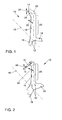
- the first preferred embodiment shown in Fig. 1 of an inventive Device 10 for torque transmission from a driving, not shown Shaft, for example a crankshaft of an internal combustion engine, on a not illustrated driven shaft, for example a transmission input shaft of a Transmission comprises a radially inner mounting 12 for the driving shaft and a radially outer fastening 14 for the driven shaft, here the Expression "shaft” also includes corresponding attachments on the rotating bodies, such as for example flywheel or torsional vibration damper, which with the corresponding fasteners 12, 14 of the device 10 can be connected.
- the Device 10 rotates together with the shafts about an axis of rotation 16.
- In the in 1 shows these three identically designed arms 18 of which only one is shown in full. The same functionality can, however basically also using a larger or smaller number appropriately shaped arms can be achieved, which are not necessarily the same shape have to.
- the device on arm 18 with a first deformation region 20 appropriate elasticity in which the arm 18 deform elastically and a Can perform movement according to arrow 22.
- the device 10 an axial Compensates for misalignment between the shafts, without corresponding forces from the driving to transmit to the driven shaft.
- a tab 24 At an end of the arm 18 facing away from the radially inner fastening 12 this is bent at right angles, so that it is perpendicular to the arm 18 and parallel to the Axis of rotation 16 extends a tab 24, the radially outside at its free end lying attachment 14 carries.
- This tab 24 points between the bend and the fastening 14 lying radially on the outside has a second deformation region 28 appropriate elasticity, so that the tab 24 deform elastically and a Can perform movement according to arrow 26.
- This is a radial Relative movement between the radially inner fastening 12 and the radial one external attachment 14 possible, so that the device 10 a radial Compensates for misalignment between the shafts, without corresponding forces from the driving to transmit to the driven shaft.
- the device 10 is thus designed as a connecting element such that although the torque, but not the axial and radial constraining forces of one Transfer the primary side (driving shaft) to the secondary side (driven shaft) become.
- the radially outer fastening 14 can be attached corresponding component on the driven shaft, such as a Inertia are adjusted accordingly. This is simply that to form elastic element 30 accordingly. Since none in the circumferential direction Deformation area exists, the torque transmission takes place without play.
Landscapes
- Engineering & Computer Science (AREA)
- General Engineering & Computer Science (AREA)
- Mechanical Engineering (AREA)
- Shafts, Cranks, Connecting Bars, And Related Bearings (AREA)
Abstract
Description
- Fig. 1
- eine erste bevorzugte Ausführungsform einer erfindungsgemäßen Vorrichtung zur Drehmomentübertragung in schematischer perspektivischer Ansicht und
- Fig. 2
- eine zweite bevorzugte Ausführungsform einer erfindungsgemäßen Vorrichtung zur Drehmomentübertragung in schematischer perspektivischer Ansicht.
- 10
- Vorrichtung zur Drehmomentübertragung
- 12
- radial innen liegende Befestigung
- 14
- radial außen liegende Befestigung
- 16
- Drehachse
- 18
- Arm
- 20
- erster Verformungsbereich
- 22
- Pfeil
- 24
- Lasche
- 26
- Pfeil
- 28
- zweiter Verformungsbereich
- 30
- elastische Element
Claims (3)
- Vorrichtung (10) zur Drehmomentübertragung von einer antreibenden Welle auf eine angetriebene Welle, wobei die Vorrichtung (10) eine radial innen liegende Befestigung (12) für eine der beiden Wellen und eine radial außen liegende Befestigung (14) für die entsprechend andere Welle aufweist, dadurch gekennzeichnet, daß die Vorrichtung (10) zwischen der radial innen liegenden Befestigung (12) und der radial außen liegenden Befestigung (14) einen ersten Verformungsbereich (20) aufweist, welcher mittels elastischer Verformung eine axiale Relativbewegung (22) zwischen der radial innen liegenden Befestigung (12) und der radial außen liegenden Befestigung (14) ermöglicht, und daß die Vorrichtung (10) an der radial außen liegenden Befestigung (14) eine sich parallel zu den Wellen erstreckende Lasche (24) mit einem zweiten Verformungsbereich (28) aufweist, welcher mittels elastischer Verformung eine radiale Relativbewegung (26) zwischen der radial innen liegenden Befestigung (12) und der radial außen liegenden Befestigung (14) ermöglicht.
- Vorrichtung (10) nach Anspruch 1, dadurch gekennzeichnet, daß die antreibende Welle eine Kurbelwelle einer Brennkraftmaschine und die angetriebene Welle eine Getriebeeingangswelle eines Getriebes ist.
- Vorrichtung (10) nach Anspruch 1 oder 2, dadurch gekennzeichnet, daß an der Lasche (24) ein elastischer Verbinder (30) angeordnet ist, welcher die radial außen liegende Befestigung (14) sowie den zweiten Verformungsbereich (28) trägt.
Applications Claiming Priority (2)
| Application Number | Priority Date | Filing Date | Title |
|---|---|---|---|
| DE2001140067 DE10140067A1 (de) | 2001-08-16 | 2001-08-16 | Vorrichtung zur Drehmomentübertragung |
| DE10140067 | 2001-08-16 |
Publications (1)
| Publication Number | Publication Date |
|---|---|
| EP1288516A1 true EP1288516A1 (de) | 2003-03-05 |
Family
ID=7695530
Family Applications (1)
| Application Number | Title | Priority Date | Filing Date |
|---|---|---|---|
| EP02015473A Withdrawn EP1288516A1 (de) | 2001-08-16 | 2002-07-12 | Vorrichtung zur Drehmomentübertragung |
Country Status (2)
| Country | Link |
|---|---|
| EP (1) | EP1288516A1 (de) |
| DE (1) | DE10140067A1 (de) |
Citations (5)
| Publication number | Priority date | Publication date | Assignee | Title |
|---|---|---|---|---|
| DE295224C (de) * | ||||
| FR607721A (fr) * | 1924-10-21 | 1926-07-07 | Accouplement à ressorts | |
| DE3432602A1 (de) * | 1984-08-31 | 1985-04-04 | Klaus Prof. Dr.-Ing. 1000 Berlin Federn | Formfedernde drehelastische kupplung |
| DE4211619A1 (de) * | 1992-04-07 | 1993-10-14 | Schmidt Kupplung Gmbh | Kupplung zum winkeltreuen Kuppeln drehbarer Teile |
| DE4315807C1 (de) * | 1993-05-12 | 1994-12-08 | Scherdel Sigmund Tech Federn | Flexible Verbindungsanordnung zur Drehmomentübertragung |
-
2001
- 2001-08-16 DE DE2001140067 patent/DE10140067A1/de not_active Withdrawn
-
2002
- 2002-07-12 EP EP02015473A patent/EP1288516A1/de not_active Withdrawn
Patent Citations (5)
| Publication number | Priority date | Publication date | Assignee | Title |
|---|---|---|---|---|
| DE295224C (de) * | ||||
| FR607721A (fr) * | 1924-10-21 | 1926-07-07 | Accouplement à ressorts | |
| DE3432602A1 (de) * | 1984-08-31 | 1985-04-04 | Klaus Prof. Dr.-Ing. 1000 Berlin Federn | Formfedernde drehelastische kupplung |
| DE4211619A1 (de) * | 1992-04-07 | 1993-10-14 | Schmidt Kupplung Gmbh | Kupplung zum winkeltreuen Kuppeln drehbarer Teile |
| DE4315807C1 (de) * | 1993-05-12 | 1994-12-08 | Scherdel Sigmund Tech Federn | Flexible Verbindungsanordnung zur Drehmomentübertragung |
Also Published As
| Publication number | Publication date |
|---|---|
| DE10140067A1 (de) | 2003-02-27 |
Similar Documents
| Publication | Publication Date | Title |
|---|---|---|
| EP2470807B1 (de) | Verspannsystem und verfahren zum verspannen einer welle-nabe-verbindung | |
| DE102016219773B4 (de) | Kupplungsscheibe, Reibungskupplungseinrichtung und Antriebsstrang | |
| DE102015214841A1 (de) | Drehschwingungsdämpfungsanordnung, insbesondere Tilgerbaugruppe | |
| WO2007051627A1 (de) | Torsionsschwingungsdämpfer mit einer ankopplung an eine kurbelwelle sowie kombination aus einem torsionsschwingungsdämpfer und einer kupplung | |
| EP1582766A2 (de) | Torsionsschwingungsdämpfer | |
| EP2923107A1 (de) | Wandlereinheit mit einem dämpfungssystem und mit einer drehmomentübertragungs-einheit | |
| DE10319784B4 (de) | Integriertes Drehgeschwindigkeitsdämpfer-Bauteil für einen Antriebsstrang | |
| EP1431610B1 (de) | Zweimassenschwungrad | |
| DE102008014445A1 (de) | Kopplungsanordnung mit Federeinrichtung, Federeinrichtung für eine solche Kopplungsanordnung und Antriebsstrang für ein Kraftfahrzeug mit einer solchen Kopplungsanordnung | |
| DE102013214089A1 (de) | Schwingungsdämpfer, insbesondere für ein Kraftfahrzeug, sowie entsprechende Reibkupplung und entsprechendes Kraftfahrzeug | |
| WO2018177468A1 (de) | Welle-nabe-verbindung mit verspannelement für steckverzahnungen sowie antriebsstrang | |
| EP1496288B1 (de) | Torsionsschwingungsdämpfer | |
| DE102010055341A1 (de) | Exzentrische Kurbelwellenlagerung mit Zweimassenschwungrad | |
| DE102011008703B4 (de) | Vorrichtung zur trieblichen Verbindung | |
| DE102021213313B4 (de) | Welle-Nabe-Verbindung | |
| DE10338674A1 (de) | Verfahren zur Montage einer Drehmomentbeschränkungsvorrichtung mit einem Dämpfermechanismus | |
| DE10140067A1 (de) | Vorrichtung zur Drehmomentübertragung | |
| WO2003044389A1 (de) | Zweimassenschwungrad | |
| DE102016208758A1 (de) | Tilger für eine Drehmomentübertragungsvorrichtung | |
| DE102021116794B4 (de) | Drehmomentübertragungsvorrichtung und Hybridvorrichtung | |
| DE19604964A1 (de) | Schwungmassenvorrichtung mit einer Entkopplungsvorrichtung | |
| DE102020108049A1 (de) | Zweimassenschwungrad | |
| DE102015117785B4 (de) | Wellenkupplung | |
| EP3992483B1 (de) | Antriebseinheit aus einem motor, einem getriebe und einer diese verbindenden kupplung | |
| DE10243279A1 (de) | Kupplung mit konischer Verzahnung einer Welle-Nabe-Verbindung |
Legal Events
| Date | Code | Title | Description |
|---|---|---|---|
| PUAI | Public reference made under article 153(3) epc to a published international application that has entered the european phase |
Free format text: ORIGINAL CODE: 0009012 |
|
| AK | Designated contracting states |
Kind code of ref document: A1 Designated state(s): AT BE BG CH CY CZ DE DK EE ES FI FR GB GR IE IT LI LU MC NL PT SE SK TR Designated state(s): AT BE BG CH CY CZ DE DK EE ES FI FR GB GR IE IT LI LU MC NL PT SE SK TR |
|
| AX | Request for extension of the european patent |
Extension state: AL LT LV MK RO SI |
|
| 17P | Request for examination filed |
Effective date: 20030905 |
|
| AKX | Designation fees paid |
Designated state(s): CZ DE ES FR GB IT |
|
| 17Q | First examination report despatched |
Effective date: 20031022 |
|
| GRAP | Despatch of communication of intention to grant a patent |
Free format text: ORIGINAL CODE: EPIDOSNIGR1 |
|
| STAA | Information on the status of an ep patent application or granted ep patent |
Free format text: STATUS: THE APPLICATION IS DEEMED TO BE WITHDRAWN |
|
| 18D | Application deemed to be withdrawn |
Effective date: 20051117 |