EP1288411A2 - Boat-propulsion equipment having a theft-prevention device - Google Patents
Boat-propulsion equipment having a theft-prevention device Download PDFInfo
- Publication number
- EP1288411A2 EP1288411A2 EP02026106A EP02026106A EP1288411A2 EP 1288411 A2 EP1288411 A2 EP 1288411A2 EP 02026106 A EP02026106 A EP 02026106A EP 02026106 A EP02026106 A EP 02026106A EP 1288411 A2 EP1288411 A2 EP 1288411A2
- Authority
- EP
- European Patent Office
- Prior art keywords
- key
- identification code
- theft
- characteristic identification
- key position
- Prior art date
- Legal status (The legal status is an assumption and is not a legal conclusion. Google has not performed a legal analysis and makes no representation as to the accuracy of the status listed.)
- Withdrawn
Links
Images


Classifications
-
- B—PERFORMING OPERATIONS; TRANSPORTING
- B63—SHIPS OR OTHER WATERBORNE VESSELS; RELATED EQUIPMENT
- B63J—AUXILIARIES ON VESSELS
- B63J99/00—Subject matter not provided for in other groups of this subclass
-
- E—FIXED CONSTRUCTIONS
- E05—LOCKS; KEYS; WINDOW OR DOOR FITTINGS; SAFES
- E05B—LOCKS; ACCESSORIES THEREFOR; HANDCUFFS
- E05B73/00—Devices for locking portable objects against unauthorised removal; Miscellaneous locking devices
- E05B73/007—Devices for locking portable objects against unauthorised removal; Miscellaneous locking devices for boats, surfboards or parts or accessories thereof
- E05B73/0076—Devices for locking portable objects against unauthorised removal; Miscellaneous locking devices for boats, surfboards or parts or accessories thereof outboard motors or propellers
-
- F—MECHANICAL ENGINEERING; LIGHTING; HEATING; WEAPONS; BLASTING
- F02—COMBUSTION ENGINES; HOT-GAS OR COMBUSTION-PRODUCT ENGINE PLANTS
- F02B—INTERNAL-COMBUSTION PISTON ENGINES; COMBUSTION ENGINES IN GENERAL
- F02B61/00—Adaptations of engines for driving vehicles or for driving propellers; Combinations of engines with gearing
- F02B61/04—Adaptations of engines for driving vehicles or for driving propellers; Combinations of engines with gearing for driving propellers
- F02B61/045—Adaptations of engines for driving vehicles or for driving propellers; Combinations of engines with gearing for driving propellers for outboard marine engines
-
- F—MECHANICAL ENGINEERING; LIGHTING; HEATING; WEAPONS; BLASTING
- F02—COMBUSTION ENGINES; HOT-GAS OR COMBUSTION-PRODUCT ENGINE PLANTS
- F02N—STARTING OF COMBUSTION ENGINES; STARTING AIDS FOR SUCH ENGINES, NOT OTHERWISE PROVIDED FOR
- F02N15/00—Other power-operated starting apparatus; Component parts, details, or accessories, not provided for in, or of interest apart from groups F02N5/00 - F02N13/00
- F02N15/10—Safety devices not otherwise provided for
-
- F—MECHANICAL ENGINEERING; LIGHTING; HEATING; WEAPONS; BLASTING
- F02—COMBUSTION ENGINES; HOT-GAS OR COMBUSTION-PRODUCT ENGINE PLANTS
- F02P—IGNITION, OTHER THAN COMPRESSION IGNITION, FOR INTERNAL-COMBUSTION ENGINES; TESTING OF IGNITION TIMING IN COMPRESSION-IGNITION ENGINES
- F02P1/00—Installations having electric ignition energy generated by magneto- or dynamo- electric generators without subsequent storage
- F02P1/08—Layout of circuits
- F02P1/083—Layout of circuits for generating sparks by opening or closing a coil circuit
Definitions
- This invention relates to a boat propulsion equipment having a theft-prevention device.
- boats are equipped with boat propulsion equipment, any boat may be stolen by driving this boat propulsion equipment. Accordingly, they have hitherto been equipped with mechanisms that mechanically lock the boat propulsion equipment so that it becomes impossible to steer.
- a possible way to prevent the theft of boat propulsion equipment is to use a characteristic identification code for driving the boat propulsion equipment and to allow the equipment to be driven when it is operated with a key having this characteristic identification code, but there are problems associated with this approach, such as the fact that batteries are not fitted in boat propulsion equipment.
- This invention has been made in the light of such points, and it is an object of the invention to provide a boat propulsion equipment having a theft-prevention device that facilitates theft prevention by electronic means yet is convenient to use.
- a boat propulsion equipment having a theft-prevention device comprising a key having a characteristic identification code, a key cylinder which has a first key position in which the key can be inserted and removed and a second key position, which is arrived at by operating the key from this first key position, in which the characteristic identification code can be read, and a controller adapted to compare the characteristic identification code read at the said second key position with the predetermined reference code, and to allow the engine of the propulsion equipment to be started only when it matches the reference code.
- a lock means adapted to disable the removal of the said key having the characteristic identification code in the said second key position.
- a boat propulsion equipment having a theft-prevention device comprises a key having a characteristic identification code, a reader which is provided in the boat propulsion equipment for reading the said characteristic identification code when the said key is inserted, a controller that compares this characteristic identification code with a preset reference code and allows an engine of said propulsion equipment to be started only when it matches the reference code, and a manual power generator for generating electric energy required for reading and judging the said characteristic identification code.
- the manual power generator comprises a fly wheel magnet and a manual starter that operates this fly wheel magnet.
- the theft-prevention device for boat propulsion equipment is equipped with an ignition controller which performs ignition by issuing an ignition signal according to the permission signal from the said controller.
- an ignition signal is issued according to a permission signal from the controller, and since no permission signal is issued otherwise it is possible to prevent theft with greater security.
- the fly wheel magnet has a charge coil, of which one output end is connected to the ignition system and the other output end is connected to a power supply circuit, and a pulser coil that obtains the ignition timing of the ignition system, wherein an output inhibit circuit is provided to inhibit the output of said charge coil toward the ignition system.
- an inhibiting signal is only issued when the characteristic identification code has been compared with the predetermined reference code and has been found not to match the reference code, whereby it is possible to prevent theft with greater security by prohibiting the output of the charge coil toward the ignition system.
- the fly wheel magnet has a charge coil, of which one output end is connected to the ignition system and the other output end is earthed, and a pulser coil which obtains the ignition timing of the ignition system, the output end of the said charge coil on the ignition system side being connected to a power supply circuit and the ignition system in parallel, wherein an output inhibit circuit is provided to inhibit the output of said charge coil toward the ignition system.
- the fly wheel magnet has a charge coil, of which one output end is connected in parallel to the ignition system and power supply circuit and the other output end is earthed, and a pulser coil which obtains the ignition timing of the ignition system, and which is equipped with a rotation limiter circuit that imposes a fixed limit on the output rate of ignition pulses from the said ignition system, this rotation limiter circuit being operated when the said controller cannot be operated.
- the fly wheel magnet has a charge coil, of which one output end is connected in parallel to the ignition system and power supply circuit and the other output end is earthed, and a pulser coil which obtains the ignition timing of the ignition system, and in which the said controller drives the ignition system from the time at which the said manual power generator is started until the characteristic identification code is judged, continuing to drive the ignition system when the characteristic identification code matches the reference code, and ceasing to drive the ignition system when the codes do not match.
- the engine in said first key position the engine can be stopped, and in said second key position the power supply is made available.
- the key cylinder has a third key position - which is arrived at by operating the key from this second key position - in which the starter motor can be driven.
- the theft-prevention device is equipped with a lock means that disables removal of the said key having a characteristic identification code in the said second key position and third key position, and a controller that compares the characteristic identification code read at the said second key position and third key position with the predetermined reference code, and allows the engine to be started, preferably by issuing a permission signal only when it matches the reference code.
- the ignition system is driven from the time at which the manual power generator is manually started until the characteristic identification code has been judged, and the driving of the ignition system is either continued when the characteristic identification codes matches the reference code or stopped when the codes do not match, whereby the device is capable of battery-less operation without prolonging the time between the manual starting of the manual power generator and the firing of the engine, i.e. without impairing the startability.
- Figure 1 is a side view of a boat on which boat propulsion equipment provided with a theft-prevention device is mounted
- Figure 2 shows the arrangement of the theft-prevention device for boat propulsion equipment
- Figure 3 outlines the configuration of the theft-prevention device for boat propulsion equipment
- Figure 4 is an operation flow chart of the theft-prevention device for boat propulsion equipment.
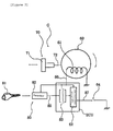
- Boat 1 has a hull 2, and an outboard motor 3 is removably attached to the stern of this hull 2 as boat propulsion equipment; arrow Fr indicates the front of boat 1 in the direction of travel.
- This outboard motor 3 consists of a bracket 4 attached to the stern, and an outboard motor body 6 pivoted on this bracket 4 by a pivot shaft 5 (which is arranged in a plane perpendicular to the direction of travel).
- Outboard motor body 6 has a transmission case 9 which constitutes its outer shell, and a transmission mechanism 10 which is accommodated inside this transmission case 9.
- Transmission case 9 can rock to the right and left about a pivot shaft 7 disposed more or less vertically with respect to swivel bracket 6a, and swivel bracket 6a is supported by pivot shaft 5 in the up/down direction with respect to bracket 4.
- an engine 11 is mounted in outboard motor body 6; engine 11 is removably attached to the upper end of transmission case 9, and is covered, with freedom to open and close, by lower cowling 12a and upper cowling 12b. Upper cowling 12b is also covered with a top cowling 12c.
- Transmission case 9 extends down into the water and provides support for a propeller shaft 13 which extends rearward at the bottom end of this transmission case 9; a propeller 14 is attached to this propeller shaft 13.
- Engine 11 has a cylinder body 41 and a crankcase 40 common to each cylinder, an upright crankshaft 42 whose central axis is almost vertical is accommodated at the adjoining parts of crankcase 40 and cylinder body 41, and this crankshaft 42 is supported by crankcase 40 and cylinder body 41 with freedom to rotate about the central axis thereof.
- a cylinder head 43 is removably attached to cylinder body 41, and spark plugs 44 are attached to cylinder head 43 corresponding to each cylinder.
- a throttle body 45 is attached to crankcase 40, and this throttle body 45 is provided with an intake duct 45a and a throttle valve 45b which controls the intake air capacity.
- An intake air silencer 46 is attached to throttle body 45, and by disposing intake air silencer 46 on the upstream side of throttle body 45, intake air silencer 46 is able to function as an intake air chamber, reducing fuel blowback, air intake noise and engine noise.
- a drive shaft 50 which constitutes transmission mechanism 10 is connected to the bottom end part of crankshaft 42, and this drive shaft 50 is connected to propeller shaft 13 via a forward/reverse switching mechanism 51.
- a known fly wheel magnet 60 and manual starter 70 are disposed inside top cowling 12c, and the handle 71 of manual starter 70 is made to project forward - i.e. toward the hull - from the front surface of top cowling 12c.
- Fly wheel magnet 60 has a charge coil 61 that generates electricity from the rotation of crankshaft 42 and ignition controller 62 is driven by the power generated in this charge coil 61, whereby spark plugs 44 are made to spark at a prescribed ignition timing.
- This outboard motor 3 is equipped with a theft-prevention device 80.
- Theft-prevention device 80 has a key 81 which has a characteristic identification code, a reader 82 which reads the characteristic identification code when this key 81 is inserted, a controller 83 which issues a permission signal only when this characteristic identification code has been read in and compared with a predetermined reference code established beforehand and the codes have been found to match, an ignition controller 89 which causes ignition by issuing an ignition signal according to the permission signal from controller 83, and a manual power generator G which supplies drive electric power for reading and judging the characteristic identification code.
- the electric power from charge coil 61 of fly wheel magnet 60, which constitutes manual power generator G, is used as a reading power source for reader 82 and a judgment power source for controller 83.
- Reader 82 is disposed on the hull side of lower cowling 12a, and allows key 81 to be inserted from the outside of lower cowling 12a. In this way because reader 82 and handle 71 are disposed close to each other on the hull side, it is easy to insert key 81 from the hull side and to operate handle 71.
- Controller 83 and ignition controller 89 are provided in an engine control unit ECU.
- This engine control unit ECU is incorporated into the side of crankcase 40, and as Figure 2 shows it is wired to reader 82 and fly wheel magnet 60 and is also wired to spark plugs 44.
- reader 82, fly wheel magnet 60 and spark plug 44 can be located around the engine control unit ECU, and it is easy to provide them with wiring 85, 86 and 87 respectively.
- Manual power generator G comprises a fly wheel magnet 60 and a manual starter 70 that causes this fly wheel magnet 60 to rotate; by using the manual starter 70 to operate fly wheel magnet 60, it is possible to supply drive electric power for judging the characteristic identification code without using a dedicated manual power generator.
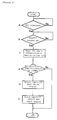
- step a a decision is made as to whether or not key 81 has been inserted in reader 82, and when manual starter 70 is operated while this key 81 is inserted (step b), the characteristic identification code of key 81 is read in (step c).
- step d the characteristic identification code read when key 81 was inserted is compared with a predetermined reference code, and the process stops without turning on the ignition if the codes do not match, so the engine cannot be started.
- controller 83 issues a permission signal (step e), and ignition controller 89 thereby issues an ignition signal so that the engine starts (step f).
- Figure 5 is a specific circuit diagram showing a theft-prevention device for boat propulsion equipment.
- the theft-prevention device for boat propulsion equipment has: a key 81 having a characteristic identification code, a reader 82 which is provided in the boat propulsion equipment and which reads the characteristic identification code when key 81 is inserted, a controller 83 which compares this characteristic identification code with a predetermined reference code and issues an inhibiting signal when the codes do no match, and a manual power generator G which supplies drive electric power for reading and judging the characteristic identification code.
- This manual power generator G comprises a fly wheel magnet 60 and a manual starter 70 which operates this fly wheel magnet 60.
- Fly wheel magnet 60 has a charge coil 61, of which one output end 61a is connected to ignition system 100 and the other output end 61b is connected to power supply circuit 101, and a pulser coil 62 which obtains the ignition timing of ignition system 100.
- Ignition system 100 consists of an ignition capacitor C1, ignition circuits 120, ignition coils 121 and waveform shaping circuits 122. Waveform shaping of the ignition timing signal from pulser coil 62 is performed by waveform shaping circuits 122, and the voltage of ignition capacitor C1 is applied to the primary side of ignition coils 121 by making ignition circuits 120 conduct at a specific timing, whereby a high voltage is produced at the secondary side and sparks are produced in spark plugs 123.
- This theft-prevention device for boat propulsion equipment is equipped with an output inhibit circuit 110 which issues an inhibiting signal to prevent charge coil 61 from outputting toward the ignition system.
- a stop switch SW1 is also connected to prevent charge coil 61 from outputting toward the ignition system.
- Control unit 200 comprises reader 82, controller 83, ignition capacitor C1, ignition circuits 120, ignition coils 121 and waveform shaping circuits 122, and output inhibit circuit 110.
- the characteristic identification code is compared with a predetermined reference code and an inhibiting signal is only issued when the codes do not match, thereby prohibiting charge coil 61 from outputting toward the ignition system and enabling secure theft prevention.
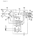
- Figure 6 is a circuit diagram showing another embodiment of a theft-prevention device for boat propulsion equipment.
- One output end 61a of charge coil 61 of fly wheel magnet 60 is connected in parallel to ignition system 100 and power supply circuit 101, and the other output end 61b is earthed.
- the ignition capacitor C1 of ignition system 100 is connected in parallel with power supply circuit 101, and stop switch SW1 and output inhibit circuit 110 are connected between power supply circuit 101 and output end 61a.
- controller 83 can stop ignition system 100 when the characteristic identification code is different, whereby theft can be prevented with greater security.
- the theft-prevention device for boat propulsion equipment is equipped with a rotation limiter circuit 300 which imposes a fixed limit on the output rate of ignition pulses from ignition system 100, and this rotation limiter circuit 300 is operated when the operation of controller 83 is inhibited.
- This rotation limiter circuit 300 imposes a fixed limit on the output rate of ignition pulses from ignition system 100 when the operation of controller 83 is inhibited. In this way, since rotation limiter circuit 300 operates when the operation of controller 83 has been inhibited, the boat cannot be used normally and becomes worthless when stolen. It is also possible for a user having the correct key to return to port without hindrance by operating below the rotation speed of the limiter.
- the theft-prevention device for boat propulsion equipment is also equipped with a controller 83 - this controller 83 drives ignition system 100 from the time at which manual power generator G is manually started until the characteristic identification code has been judged, and either continues to drive ignition system 100 if the characteristic identification code matches the reference code or stops driving ignition system 100 if the codes do not match.
- the device is capable of battery-less operation without impairing the startability of the boat - i.e. without prolonging the time between the manual starting of manual power generator G and the initial firing of the engine.
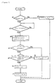
- Figure 7 is an operational flow chart of the theft-prevention device for boat propulsion equipment.
- step al a judgment is made as to whether or not controller 83 is operating normally - since normal usage is impossible when the operation of controller 83 is inhibited because rotation limiter circuit 300 operates, the boat becomes worthless when stolen (step b1).
- step cl When controller 83 is operating normally at step al, a judgment is made at step cl as to whether or not a key has been inserted, and when a key 81 has been inserted, the characteristic identification code of key 81 is read in (step dl).
- step el a decision is made regarding the presence or absence of a code signal from the characteristic identification code - when there is no code signal, an ignition inhibiting signal is issued and charge coil 61 is prevented from outputting toward the ignition system, thereby facilitating secure theft prevention (step f1).
- the characteristic identification code is judged at step gl - if the characteristic identification code does not match the reference code, the process shifts to step fl, where an ignition inhibiting signal is issued and charge coil 61 is prevented from outputting toward the ignition system, thereby facilitating secure theft prevention
- step h1 ignition is permitted (step h1), and the engine starts (step il).
- Figure 8 and Figure 9 show a further embodiment of a theft-prevention device for boat propulsion equipment -
- Figure 8 shows the key operation part and the key operations
- Figure 9 is a circuit diagram of the theft-prevention device.
- Charge coil 501, pulser coil 502 and ignition coil 503 are connected to control unit 500.
- control unit 500 an ignition signal with a specific timing is output according to the ignition timing signal of pulser coil 502, and a voltage is applied to the primary side 503a of ignition coil 503, whereby a high voltage is generated in secondary side 503b and a spark is produced in spark plug 504.
- a stop switch 505, which is attached to cowling 510 of outboard motor 3, is connected to control unit 500, and stop switch 505 allows the engine to be stopped by stopping the output of ignition signals.
- a key cylinder 520 is attached to cowling 510 - this key cylinder 520 is provided with an antenna coil 521, and this antenna coil 521 is connected to a controller 522 built into control unit 500.
- a key insertion hole 523 is formed in key cylinder 520, and this key insertion hole 523 allows the insertion and removal of a key 525 having a characteristic identification code 524.
- This theft-prevention device for boat propulsion equipment has a first key position OFF, in which the key 525 having a characteristic identification code 524 can be inserted and removed, and a second key position ON, which is reached by operating the key from this first key position OFF and in which the characteristic identification code 524 is read in and an ID signal can be transmitted.
- Key cylinder 520 is provided with a lock means 526 which disables the removal of the key 525 having a characteristic identification code 524 in the second key position ON.
- Lock means 526 is configured so as to prevent the removal of key 525 by a mechanical mechanism.
- the characteristic identification code 524 is read by antenna coil 521, and controller 522 compares the characteristic identification code 524 read in at second key position ON with the predetermined reference code, only issuing a permission signal and allowing the engine to start when it matches the reference code.
- the engine is started with a manual starter.
- Figure 10 and Figure 11 show a further embodiment of a theft-prevention device for boat propulsion equipment -
- Figure 10 shows the key operation part and key operations
- Figure 11 is a circuit diagram of the theft-prevention device. The description of this embodiment is simplified by using the same reference numerals for parts having the same constitution as those in Figure 8 and Figure 9.
- Cowling 510 of outboard motor 3 is provided with a connector 550, and is connected to key cylinder 520 and stop switch 505 via connector 550. That is to say, key cylinder 520 and stop switch 505 are connected to control unit 500 by line W, and are earthed by line B. Also, key cylinder 520 is connected to rectifier regulator 551 and battery 552 by line R, is connected to starter relay 553 by line Br, and is earthed by line Y. Rectifier regulator 551 adjusts the output voltage of a light coil 554 to a fixed voltage. Starter motor 555 is connected to battery 552 by operating starter relay 553, whereby starter motor 555 is driven and the engine is started.
- This theft-prevention device for boat propulsion equipment has a first key position OFF in which a key 525 having a characteristic identification code 524 can be inserted and removed and in which the engine can be stopped, a second key position ON which is arrived at by operating the key from this first key position OFF, and in which it is possible to transmit an ID signal whereby the characteristic identification code 524 is read and to provide a source of power, and a third key position START which is arrived at by operating the key from second key position ON, and in which starter motor 555 can be driven.
- Key cyLinder 520 is provided with a lock means 526 which disables the removal of key 525 having a characteristic identification code 524 in the second key position ON and third key position START. Lock means 526 is configured so as to disable the removal of key 525 by a mechanical mechanism.
- characteristic identification code 524 can be read in, a supply of power can be made available, and removal of the key can be prevented. Furthermore, by performing a single key operation from second key position ON to third key position START, a permission signal is issued and the engine can be started by driving the starter motor only when characteristic identification code 524 matches the reference code, removal of the key can also be prevented, making the key more convenient to use, and moreover, a single key can be used for theft prevention and for driving the engine, thereby reducing the number of components and lowering the cost of the device.
- a theft-prevention device for boat propulsion equipment comprises a key 81 having a characteristic identification code, a reader 82 on the propulsion equipment and a controller 83 for comparing the identification code with a code prestored on the propulsion equipment.
- a manual power generator G is provided for generating the electric current required for identifying the correct key by the controller.
Abstract
Description
- This invention relates to a boat propulsion equipment having a theft-prevention device.
- Although boats are equipped with boat propulsion equipment, any boat may be stolen by driving this boat propulsion equipment. Accordingly, they have hitherto been equipped with mechanisms that mechanically lock the boat propulsion equipment so that it becomes impossible to steer.
- But conventional mechanical lock mechanisms cannot cope with situations where the boat propulsion equipment is itself stolen by removing it from the boat. A possible way to prevent the theft of boat propulsion equipment is to use a characteristic identification code for driving the boat propulsion equipment and to allow the equipment to be driven when it is operated with a key having this characteristic identification code, but there are problems associated with this approach, such as the fact that batteries are not fitted in boat propulsion equipment.
- The use of a key having a characteristic identification code also increases the number of keys required for the boat, which is a source of inconvenience for whoever uses the boat and gives rise to other problems such as increased costs due to the larger number of components.
- This invention has been made in the light of such points, and it is an object of the invention to provide a boat propulsion equipment having a theft-prevention device that facilitates theft prevention by electronic means yet is convenient to use.
- This object is solved by a boat propulsion equipment having a theft-prevention device comprising a key having a characteristic identification code, a key cylinder which has a first key position in which the key can be inserted and removed and a second key position, which is arrived at by operating the key from this first key position, in which the characteristic identification code can be read, and a controller adapted to compare the characteristic identification code read at the said second key position with the predetermined reference code, and to allow the engine of the propulsion equipment to be started only when it matches the reference code.
- By moving the key from a first key position to a second key position with a single key action, it is possible to read the characteristic identification code.
- Preferably, a lock means adapted to disable the removal of the said key having the characteristic identification code in the said second key position.
- Therefore, by moving the key from a final key position to a second key position with a single key action, it is possible to disable removal of the key, which makes it possible to prevent the key from falling out and makes the device more convenient to use.
- Further preferably, a boat propulsion equipment having a theft-prevention device comprises a key having a characteristic identification code, a reader which is provided in the boat propulsion equipment for reading the said characteristic identification code when the said key is inserted, a controller that compares this characteristic identification code with a preset reference code and allows an engine of said propulsion equipment to be started only when it matches the reference code, and a manual power generator for generating electric energy required for reading and judging the said characteristic identification code.
- As drive electric power for reading and judging the characteristic identification code is supplied by driving a manual power generator, it is possible to prevent theft by electronic means based on a characteristic identification code even when there is no battery on the propulsion equipment.
- According to another preferred embodiment of the theft-prevention device, the manual power generator comprises a fly wheel magnet and a manual starter that operates this fly wheel magnet.
- By using a manual starter to operate the fly wheel magnet, it is possible to supply drive electric power for judging the characteristic identification code without using a dedicated manual generator.
- Preferably the theft-prevention device for boat propulsion equipment is equipped with an ignition controller which performs ignition by issuing an ignition signal according to the permission signal from the said controller.
- Accordingly, an ignition signal is issued according to a permission signal from the controller, and since no permission signal is issued otherwise it is possible to prevent theft with greater security.
- According to still another embodiment of the theft-prevention device the fly wheel magnet has a charge coil, of which one output end is connected to the ignition system and the other output end is connected to a power supply circuit, and a pulser coil that obtains the ignition timing of the ignition system, wherein an output inhibit circuit is provided to inhibit the output of said charge coil toward the ignition system.
- Accordingly, an inhibiting signal is only issued when the characteristic identification code has been compared with the predetermined reference code and has been found not to match the reference code, whereby it is possible to prevent theft with greater security by prohibiting the output of the charge coil toward the ignition system.
- In another embodiment, the fly wheel magnet has a charge coil, of which one output end is connected to the ignition system and the other output end is earthed, and a pulser coil which obtains the ignition timing of the ignition system, the output end of the said charge coil on the ignition system side being connected to a power supply circuit and the ignition system in parallel, wherein an output inhibit circuit is provided to inhibit the output of said charge coil toward the ignition system.
- Thus , there is also no supply of power to the ignition system when a diode, for example, is inserted in the power supply line from the output end of the charge coil, making ignition impossible. Also, even if the power supply line fed from the fly wheel magnet is manipulated from outside, the power supply circuit still operates so that the controller can stop the ignition system when the characteristic identification code is different, whereby it is possible to prevent theft with greater security.
- According to another embodiment of the theft prevention device, the fly wheel magnet has a charge coil, of which one output end is connected in parallel to the ignition system and power supply circuit and the other output end is earthed, and a pulser coil which obtains the ignition timing of the ignition system, and which is equipped with a rotation limiter circuit that imposes a fixed limit on the output rate of ignition pulses from the said ignition system, this rotation limiter circuit being operated when the said controller cannot be operated.
- By controlling the output rate of ignition pulses in the ignition system when it is disabled by the controller, it is possible to prevent theft because the speed of the boat does not increase, and it is also possible for the user having the correct key to return to port without hindrance.
- According to another embodiment of the theft-prevention device, the fly wheel magnet has a charge coil, of which one output end is connected in parallel to the ignition system and power supply circuit and the other output end is earthed, and a pulser coil which obtains the ignition timing of the ignition system, and in which the said controller drives the ignition system from the time at which the said manual power generator is started until the characteristic identification code is judged, continuing to drive the ignition system when the characteristic identification code matches the reference code, and ceasing to drive the ignition system when the codes do not match.
- Preferably, in said first key position the engine can be stopped, and in said second key position the power supply is made available. Further, the key cylinder has a third key position - which is arrived at by operating the key from this second key position - in which the starter motor can be driven.
- Also, the theft-prevention device is equipped with a lock means that disables removal of the said key having a characteristic identification code in the said second key position and third key position, and a controller that compares the characteristic identification code read at the said second key position and third key position with the predetermined reference code, and allows the engine to be started, preferably by issuing a permission signal only when it matches the reference code.
- By moving the key from a first key position to a second key position with a single key action, it is possible to read the characteristic identification code and provide a supply of electrical power, and to disable removal of the key. Furthermore, by moving the key from the second key position to a third key position with a single key action, it is possible to start the engine by driving the starter motor only when the characteristic identification code matches the reference code and a permission signal is issued, and removal of the key can be disabled, whereby the key is easy to use and the reduced number of components - resulting from the use of a single key for theft prevention and engine starting - means that the cost is also lower.
- The ignition system is driven from the time at which the manual power generator is manually started until the characteristic identification code has been judged, and the driving of the ignition system is either continued when the characteristic identification codes matches the reference code or stopped when the codes do not match, whereby the device is capable of battery-less operation without prolonging the time between the manual starting of the manual power generator and the firing of the engine, i.e. without impairing the startability.
- Further preferred embodiments are subject to the subclaims.
- The further features and advantages of the invention will become apparent from the description of the embodiments as shown in the appended drawings.
- Fig. 1 is a side view of a boat on which boat propulsion equipment provided with a theft-prevention device is mounted.
- Fig. 2 shows the arrangement of the theft-prevention device for boat propulsion equipment.
- Fig. 3 is an outline of the configuration of the theft-prevention device for boat propulsion equipment.
- Fig. 4 is an operation flow chart of the theft-prevention device for boat propulsion equipment.
- Fig. 5 is a specific circuit diagram showing a theft-prevention device for boat propulsion equipment.
- Fig. 6 is a circuit diagram showing another embodiment of a theft-prevention device for boat propulsion equipment.
- Fig. 7 is an operational flow chart of the theft-prevention device for boat propulsion equipment.
- Fig. 8 shows the key operation part and the key operations.
- Fig. 9 is a circuit diagram of the theft-prevention device.
- Fig. 10 shows the key operation part and the key operations.
- Fig. 11 is a circuit diagram of the theft-prevention device.
-
- Figure 1 is a side view of a boat on which boat propulsion equipment provided with a theft-prevention device is mounted, Figure 2 shows the arrangement of the theft-prevention device for boat propulsion equipment, Figure 3 outlines the configuration of the theft-prevention device for boat propulsion equipment, and Figure 4 is an operation flow chart of the theft-prevention device for boat propulsion equipment.
-
Boat 1 has ahull 2, and anoutboard motor 3 is removably attached to the stern of thishull 2 as boat propulsion equipment; arrow Fr indicates the front ofboat 1 in the direction of travel. Thisoutboard motor 3 consists of abracket 4 attached to the stern, and anoutboard motor body 6 pivoted on thisbracket 4 by a pivot shaft 5 (which is arranged in a plane perpendicular to the direction of travel).Outboard motor body 6 has atransmission case 9 which constitutes its outer shell, and atransmission mechanism 10 which is accommodated inside thistransmission case 9.Transmission case 9 can rock to the right and left about apivot shaft 7 disposed more or less vertically with respect toswivel bracket 6a, andswivel bracket 6a is supported bypivot shaft 5 in the up/down direction with respect tobracket 4. - Also, an
engine 11 is mounted inoutboard motor body 6;engine 11 is removably attached to the upper end oftransmission case 9, and is covered, with freedom to open and close, by lower cowling 12a and upper cowling 12b. Upper cowling 12b is also covered with a top cowling 12c.Transmission case 9 extends down into the water and provides support for apropeller shaft 13 which extends rearward at the bottom end of thistransmission case 9; apropeller 14 is attached to thispropeller shaft 13. -
Engine 11 has acylinder body 41 and acrankcase 40 common to each cylinder, anupright crankshaft 42 whose central axis is almost vertical is accommodated at the adjoining parts ofcrankcase 40 andcylinder body 41, and thiscrankshaft 42 is supported bycrankcase 40 andcylinder body 41 with freedom to rotate about the central axis thereof. - A
cylinder head 43 is removably attached tocylinder body 41, andspark plugs 44 are attached tocylinder head 43 corresponding to each cylinder. - A throttle body 45 is attached to
crankcase 40, and this throttle body 45 is provided with anintake duct 45a and athrottle valve 45b which controls the intake air capacity. Anintake air silencer 46 is attached to throttle body 45, and by disposingintake air silencer 46 on the upstream side of throttle body 45,intake air silencer 46 is able to function as an intake air chamber, reducing fuel blowback, air intake noise and engine noise. - A
drive shaft 50 which constitutestransmission mechanism 10 is connected to the bottom end part ofcrankshaft 42, and thisdrive shaft 50 is connected topropeller shaft 13 via a forward/reverse switching mechanism 51. In the upper end part ofcrankshaft 42, a knownfly wheel magnet 60 andmanual starter 70 are disposed inside top cowling 12c, and thehandle 71 ofmanual starter 70 is made to project forward - i.e. toward the hull - from the front surface of top cowling 12c. -
Manual starter 70forces crankshaft 42 to turn whenrope 72 is pulled byhandle 71, and is thereby able to startengine 11.Fly wheel magnet 60 has acharge coil 61 that generates electricity from the rotation ofcrankshaft 42 andignition controller 62 is driven by the power generated in thischarge coil 61, wherebyspark plugs 44 are made to spark at a prescribed ignition timing. - This
outboard motor 3 is equipped with a theft-prevention device 80. Theft-prevention device 80 has akey 81 which has a characteristic identification code, areader 82 which reads the characteristic identification code when thiskey 81 is inserted, acontroller 83 which issues a permission signal only when this characteristic identification code has been read in and compared with a predetermined reference code established beforehand and the codes have been found to match, an ignition controller 89 which causes ignition by issuing an ignition signal according to the permission signal fromcontroller 83, and a manual power generator G which supplies drive electric power for reading and judging the characteristic identification code. The electric power fromcharge coil 61 offly wheel magnet 60, which constitutes manual power generator G, is used as a reading power source forreader 82 and a judgment power source forcontroller 83. - Reader 82 is disposed on the hull side of
lower cowling 12a, and allowskey 81 to be inserted from the outside oflower cowling 12a. In this way becausereader 82 andhandle 71 are disposed close to each other on the hull side, it is easy to insertkey 81 from the hull side and to operatehandle 71. -
Controller 83 and ignition controller 89 are provided in an engine control unit ECU. This engine control unit ECU is incorporated into the side ofcrankcase 40, and as Figure 2 shows it is wired toreader 82 and flywheel magnet 60 and is also wired to sparkplugs 44. By incorporating engine control unit ECU in the side ofcrankcase 40,reader 82,fly wheel magnet 60 andspark plug 44 can be located around the engine control unit ECU, and it is easy to provide them withwiring - Manual power generator G comprises a
fly wheel magnet 60 and amanual starter 70 that causes thisfly wheel magnet 60 to rotate; by using themanual starter 70 to operatefly wheel magnet 60, it is possible to supply drive electric power for judging the characteristic identification code without using a dedicated manual power generator. - Next, the operation of a theft-prevention device for boat propulsion equipment is explained based on Figure 4. In step a, a decision is made as to whether or not key 81 has been inserted in
reader 82, and whenmanual starter 70 is operated while this key 81 is inserted (step b), the characteristic identification code ofkey 81 is read in (step c). - In step d, the characteristic identification code read when key 81 was inserted is compared with a predetermined reference code, and the process stops without turning on the ignition if the codes do not match, so the engine cannot be started. When the codes do match,
controller 83 issues a permission signal (step e), and ignition controller 89 thereby issues an ignition signal so that the engine starts (step f). - In this way, drive electric power for reading and judging the characteristic identification code is supplied by driving manual power generator G, and thus theft can be prevented by electronic means on the basis of a characteristic identification code when there is no battery. Also, since an ignition signal is issued according to the permission signal from
controller 83 and no ignition signals are issued otherwise, it is possible to prevent theft even more securely. - Figure 5 is a specific circuit diagram showing a theft-prevention device for boat propulsion equipment.
- In this embodiment, the theft-prevention device for boat propulsion equipment has: a key 81 having a characteristic identification code, a
reader 82 which is provided in the boat propulsion equipment and which reads the characteristic identification code when key 81 is inserted, acontroller 83 which compares this characteristic identification code with a predetermined reference code and issues an inhibiting signal when the codes do no match, and a manual power generator G which supplies drive electric power for reading and judging the characteristic identification code. - This manual power generator G comprises a
fly wheel magnet 60 and amanual starter 70 which operates thisfly wheel magnet 60.Fly wheel magnet 60 has acharge coil 61, of which oneoutput end 61a is connected toignition system 100 and theother output end 61b is connected topower supply circuit 101, and apulser coil 62 which obtains the ignition timing ofignition system 100. -
Ignition system 100 consists of an ignition capacitor C1,ignition circuits 120, ignition coils 121 andwaveform shaping circuits 122. Waveform shaping of the ignition timing signal frompulser coil 62 is performed bywaveform shaping circuits 122, and the voltage of ignition capacitor C1 is applied to the primary side ofignition coils 121 by makingignition circuits 120 conduct at a specific timing, whereby a high voltage is produced at the secondary side and sparks are produced in spark plugs 123. - This theft-prevention device for boat propulsion equipment is equipped with an output inhibit
circuit 110 which issues an inhibiting signal to preventcharge coil 61 from outputting toward the ignition system. A stop switch SW1 is also connected to preventcharge coil 61 from outputting toward the ignition system. -
Control unit 200 comprisesreader 82,controller 83, ignition capacitor C1,ignition circuits 120, ignition coils 121 andwaveform shaping circuits 122, and output inhibitcircuit 110. - In this theft-prevention device for boat propulsion equipment, the characteristic identification code is compared with a predetermined reference code and an inhibiting signal is only issued when the codes do not match, thereby prohibiting
charge coil 61 from outputting toward the ignition system and enabling secure theft prevention. - Figure 6 is a circuit diagram showing another embodiment of a theft-prevention device for boat propulsion equipment.
- The description of the theft-prevention device for boat propulsion equipment of this embodiment is simplified by using the same reference numerals for parts having the same constitution as those in Figure 5.
- One
output end 61a ofcharge coil 61 offly wheel magnet 60 is connected in parallel toignition system 100 andpower supply circuit 101, and theother output end 61b is earthed. The ignition capacitor C1 ofignition system 100 is connected in parallel withpower supply circuit 101, and stop switch SW1 and output inhibitcircuit 110 are connected betweenpower supply circuit 101 andoutput end 61a. - When for example a diode D1 is inserted in the power source feed line from the
output end 61a ofcharge coil 61 as shown by the dashed line with two dots, there is also no supply of power to ignition capacitor C1, and accordingly ignition becomes impossible. The same effect can be achieved in other ways, such as by breaking the lead wire between theother output end 61b ofcharge coil 61 and earth. - Also, since
power supply circuit 101 still operates when the power source lines supplied fromfly wheel magnet 60 are manipulated from the outside,controller 83 can stopignition system 100 when the characteristic identification code is different, whereby theft can be prevented with greater security. - The theft-prevention device for boat propulsion equipment is equipped with a
rotation limiter circuit 300 which imposes a fixed limit on the output rate of ignition pulses fromignition system 100, and thisrotation limiter circuit 300 is operated when the operation ofcontroller 83 is inhibited. Thisrotation limiter circuit 300 imposes a fixed limit on the output rate of ignition pulses fromignition system 100 when the operation ofcontroller 83 is inhibited. In this way, sincerotation limiter circuit 300 operates when the operation ofcontroller 83 has been inhibited, the boat cannot be used normally and becomes worthless when stolen. It is also possible for a user having the correct key to return to port without hindrance by operating below the rotation speed of the limiter. - The theft-prevention device for boat propulsion equipment is also equipped with a controller 83 - this
controller 83drives ignition system 100 from the time at which manual power generator G is manually started until the characteristic identification code has been judged, and either continues to driveignition system 100 if the characteristic identification code matches the reference code or stops drivingignition system 100 if the codes do not match. - In this way, since
ignition system 100 is driven from the time at which manual power generator G is manually started until the characteristic identification code has been judged, and sinceignition system 100 either continues to be driven if the characteristic identification code matches the reference code or the driving ofignition system 100 is stopped if the codes do not match, the device is capable of battery-less operation without impairing the startability of the boat - i.e. without prolonging the time between the manual starting of manual power generator G and the initial firing of the engine. - Figure 7 is an operational flow chart of the theft-prevention device for boat propulsion equipment.
- In step al, a judgment is made as to whether or not
controller 83 is operating normally - since normal usage is impossible when the operation ofcontroller 83 is inhibited becauserotation limiter circuit 300 operates, the boat becomes worthless when stolen (step b1). - When
controller 83 is operating normally at step al, a judgment is made at step cl as to whether or not a key has been inserted, and when a key 81 has been inserted, the characteristic identification code ofkey 81 is read in (step dl). - At step el, a decision is made regarding the presence or absence of a code signal from the characteristic identification code - when there is no code signal, an ignition inhibiting signal is issued and
charge coil 61 is prevented from outputting toward the ignition system, thereby facilitating secure theft prevention (step f1). - When a characteristic identification code is present, the characteristic identification code is judged at step gl - if the characteristic identification code does not match the reference code, the process shifts to step fl, where an ignition inhibiting signal is issued and
charge coil 61 is prevented from outputting toward the ignition system, thereby facilitating secure theft prevention - Also, when the characteristic identification code matches the reference code at step gl, ignition is permitted (step h1), and the engine starts (step il).
- Figure 8 and Figure 9 show a further embodiment of a theft-prevention device for boat propulsion equipment - Figure 8 shows the key operation part and the key operations, and Figure 9 is a circuit diagram of the theft-prevention device.
Charge coil 501,pulser coil 502 andignition coil 503 are connected to controlunit 500. Incontrol unit 500, an ignition signal with a specific timing is output according to the ignition timing signal ofpulser coil 502, and a voltage is applied to theprimary side 503a ofignition coil 503, whereby a high voltage is generated insecondary side 503b and a spark is produced inspark plug 504. Also, astop switch 505, which is attached tocowling 510 ofoutboard motor 3, is connected to controlunit 500, and stopswitch 505 allows the engine to be stopped by stopping the output of ignition signals. - A
key cylinder 520 is attached to cowling 510 - thiskey cylinder 520 is provided with anantenna coil 521, and thisantenna coil 521 is connected to acontroller 522 built intocontrol unit 500. Akey insertion hole 523 is formed inkey cylinder 520, and thiskey insertion hole 523 allows the insertion and removal of a key 525 having acharacteristic identification code 524. - This theft-prevention device for boat propulsion equipment has a first key position OFF, in which the key 525 having a
characteristic identification code 524 can be inserted and removed, and a second key position ON, which is reached by operating the key from this first key position OFF and in which thecharacteristic identification code 524 is read in and an ID signal can be transmitted.Key cylinder 520 is provided with a lock means 526 which disables the removal of the key 525 having acharacteristic identification code 524 in the second key position ON. Lock means 526 is configured so as to prevent the removal ofkey 525 by a mechanical mechanism. - When key 525 is operated to the second key position ON from first key position OFF, the
characteristic identification code 524 is read byantenna coil 521, andcontroller 522 compares thecharacteristic identification code 524 read in at second key position ON with the predetermined reference code, only issuing a permission signal and allowing the engine to start when it matches the reference code. In this embodiment, the engine is started with a manual starter. - In this way, by moving to the second key position ON from the first key position OFF with a single key operation, it is possible to read in
characteristic identification code 524 and the removal ofkey 525 can be disabled by lock means 526, thereby making it possible to prevent key 525 from falling out, and making the device more convenient to use. - Figure 10 and Figure 11 show a further embodiment of a theft-prevention device for boat propulsion equipment - Figure 10 shows the key operation part and key operations, and Figure 11 is a circuit diagram of the theft-prevention device. The description of this embodiment is simplified by using the same reference numerals for parts having the same constitution as those in Figure 8 and Figure 9.
-
Cowling 510 ofoutboard motor 3 is provided with aconnector 550, and is connected tokey cylinder 520 and stopswitch 505 viaconnector 550. That is to say,key cylinder 520 and stopswitch 505 are connected to controlunit 500 by line W, and are earthed by line B. Also,key cylinder 520 is connected torectifier regulator 551 andbattery 552 by line R, is connected tostarter relay 553 by line Br, and is earthed by line Y.Rectifier regulator 551 adjusts the output voltage of alight coil 554 to a fixed voltage.Starter motor 555 is connected tobattery 552 by operatingstarter relay 553, wherebystarter motor 555 is driven and the engine is started. - This theft-prevention device for boat propulsion equipment has a first key position OFF in which a key 525 having a
characteristic identification code 524 can be inserted and removed and in which the engine can be stopped, a second key position ON which is arrived at by operating the key from this first key position OFF, and in which it is possible to transmit an ID signal whereby thecharacteristic identification code 524 is read and to provide a source of power, and a third key position START which is arrived at by operating the key from second key position ON, and in whichstarter motor 555 can be driven.Key cyLinder 520 is provided with a lock means 526 which disables the removal ofkey 525 having acharacteristic identification code 524 in the second key position ON and third key position START. Lock means 526 is configured so as to disable the removal ofkey 525 by a mechanical mechanism. - When key 525 is inserted in first key position OFF, line R is connected to line W, the
characteristic identification code 524 cannot be read byantenna coil 521, and the engine is stopped. When key 525 is operated to second key position ON from first key position OFF, line Y is connected to line R,characteristic identification code 524 is read byantenna coil 521, and thecharacteristic identification code 524 read at second key position ON is compared with a predetermined reference code incontroller 522, which issues a permission signal and allows the engine to start only when the codes match each other. Furthermore, when key 525 is operated to the third key position START from second key position ON, line R, line Y and line Br are connected together and a permission signal is issued to allow the engine to start, in whichstate starter relay 553 is operated to connectstarter motor 555 tobattery 552, and the engine is started by drivingstarter motor 555. - In this way, by performing a single key operation from first key position OFF to second key position ON,
characteristic identification code 524 can be read in, a supply of power can be made available, and removal of the key can be prevented. Furthermore, by performing a single key operation from second key position ON to third key position START, a permission signal is issued and the engine can be started by driving the starter motor only whencharacteristic identification code 524 matches the reference code, removal of the key can also be prevented, making the key more convenient to use, and moreover, a single key can be used for theft prevention and for driving the engine, thereby reducing the number of components and lowering the cost of the device. - Note that further cost reductions can be made because the constituent components of
key cylinder 520 in the embodiment of Figure 8 and Figure 9 can be used in common with the constituent components ofkey cylinder 520 in the embodiment of Figure 10 and Figure 11. Also, since the ignition works until the permission signal is issued only whencharacteristic identification code 524 matches the reference code and an ID judgment is made, it is possible to judge whether or not there is a fault in the ignition system when the engine cannot be started and fault diagnosis of the system is being carried out. - A theft-prevention device for boat propulsion equipment comprises a key 81 having a characteristic identification code, a
reader 82 on the propulsion equipment and acontroller 83 for comparing the identification code with a code prestored on the propulsion equipment. As there is no battery on the propulsion equipment, a manual power generator (G) is provided for generating the electric current required for identifying the correct key by the controller.
Claims (4)
- Boat propulsion equipment having a theft-prevention device comprising
a key (86,510) having a characteristic identification code,
a key cylinder (520) which has a first key position in which the key can be inserted and removed and a second key position, which is arrived at by operating the key from this first key position, in which the characteristic identification code can be read, and
a controller (83,522) adapted to compare the characteristic identification code read at the said second key position with the predetermined reference code, and to allow the engine (11) of the propulsion equipment (3) to be started only when it matches the reference code. - Boat propulsion equipment having a theft-prevention device according to claim 1, characterized in that in said first key position the engine (11) can be stopped, and in said second key position power supply is made available, and in that said key cylinder (520) has a third key position, which is arrived at by operating the key from this second key position, in which a starter motor can be driven, and wherein said lock means (526) is adapted to disable removal of the said key in said second key position and third key position, and said controller is adapted to compare the characteristic identification code read at the said second key position and third key position with the predetermined reference code.
- Boat propulsion equipment having a theft-prevention device according to claim 1 or 2, characterized by further comprising a lock means (526) adapted to disable the removal of the said key having the characteristic identification code in the said second key position.
- Boat propulsion equipment having a theft-prevention device according to claim 3, characterized by further comprising a manual power generator (G) for generating electric energy required for reading and judging the said characteristic identification code.
Applications Claiming Priority (5)
| Application Number | Priority Date | Filing Date | Title |
|---|---|---|---|
| JP4518198 | 1998-02-26 | ||
| JP4518198 | 1998-02-26 | ||
| JP17836598 | 1998-06-25 | ||
| JP17836598A JP4165777B2 (en) | 1997-07-09 | 1998-06-25 | Ship propulsion device anti-theft device |
| EP98120583A EP0940534B1 (en) | 1998-02-26 | 1998-10-30 | Theft-prevention device for boat propulsion equipment |
Related Parent Applications (2)
| Application Number | Title | Priority Date | Filing Date |
|---|---|---|---|
| EP98120583A Division-Into EP0940534B1 (en) | 1998-02-26 | 1998-10-30 | Theft-prevention device for boat propulsion equipment |
| EP98120583A Division EP0940534B1 (en) | 1998-02-26 | 1998-10-30 | Theft-prevention device for boat propulsion equipment |
Publications (2)
| Publication Number | Publication Date |
|---|---|
| EP1288411A2 true EP1288411A2 (en) | 2003-03-05 |
| EP1288411A3 EP1288411A3 (en) | 2003-04-09 |
Family
ID=26385164
Family Applications (2)
| Application Number | Title | Priority Date | Filing Date |
|---|---|---|---|
| EP98120583A Expired - Lifetime EP0940534B1 (en) | 1998-02-26 | 1998-10-30 | Theft-prevention device for boat propulsion equipment |
| EP02026106A Withdrawn EP1288411A3 (en) | 1998-02-26 | 1998-10-30 | Boat-propulsion equipment having a theft-prevention device |
Family Applications Before (1)
| Application Number | Title | Priority Date | Filing Date |
|---|---|---|---|
| EP98120583A Expired - Lifetime EP0940534B1 (en) | 1998-02-26 | 1998-10-30 | Theft-prevention device for boat propulsion equipment |
Country Status (2)
| Country | Link |
|---|---|
| EP (2) | EP0940534B1 (en) |
| DE (1) | DE69822783T2 (en) |
Cited By (2)
| Publication number | Priority date | Publication date | Assignee | Title |
|---|---|---|---|---|
| CN102092361A (en) * | 2009-12-09 | 2011-06-15 | 本田技研工业株式会社 | Antitheft apparatus for equipment with prime mover |
| EP2332827A1 (en) * | 2009-12-09 | 2011-06-15 | Honda Motor Co., Ltd. | Outboard motor antitheft apparatus |
Families Citing this family (3)
| Publication number | Priority date | Publication date | Assignee | Title |
|---|---|---|---|---|
| DE102008008702A1 (en) * | 2008-01-18 | 2009-07-23 | Böning Automationstechnologie GmbH & Co. KG | Device for issuing the start release for a (water) vehicle with at least two drive motors |
| JP7117339B2 (en) * | 2020-03-11 | 2022-08-12 | 本田技研工業株式会社 | Authentication device for straddle-type vehicle |
| DE102021203041B3 (en) | 2021-03-26 | 2022-09-29 | Prüfrex engineering e motion gmbh & co. kg | Detection of the actuation of a stop switch of an ignition device |
Family Cites Families (4)
| Publication number | Priority date | Publication date | Assignee | Title |
|---|---|---|---|---|
| DE4434655C2 (en) * | 1993-10-01 | 1999-08-26 | Marquardt Gmbh | Electronic ignition lock system on a motor vehicle |
| US5441022A (en) * | 1994-04-12 | 1995-08-15 | Navistar International Transportation Corp. | Vehicle ignition switch |
| JP3427572B2 (en) * | 1994-09-26 | 2003-07-22 | 株式会社デンソー | Anti-theft devices for vehicles, etc. |
| JP3731947B2 (en) * | 1996-08-08 | 2006-01-05 | 株式会社ミツバ | Engine starting device |
-
1998
- 1998-10-30 EP EP98120583A patent/EP0940534B1/en not_active Expired - Lifetime
- 1998-10-30 EP EP02026106A patent/EP1288411A3/en not_active Withdrawn
- 1998-10-30 DE DE1998622783 patent/DE69822783T2/en not_active Expired - Lifetime
Non-Patent Citations (1)
| Title |
|---|
| None |
Cited By (6)
| Publication number | Priority date | Publication date | Assignee | Title |
|---|---|---|---|---|
| CN102092361A (en) * | 2009-12-09 | 2011-06-15 | 本田技研工业株式会社 | Antitheft apparatus for equipment with prime mover |
| EP2332827A1 (en) * | 2009-12-09 | 2011-06-15 | Honda Motor Co., Ltd. | Outboard motor antitheft apparatus |
| EP2332828A1 (en) * | 2009-12-09 | 2011-06-15 | Honda Motor Co., Ltd. | Antitheft apparatus for equipment with prime mover |
| US8357018B2 (en) | 2009-12-09 | 2013-01-22 | Honda Motor Co., Ltd. | Outboard motor antitheft apparatus |
| CN102092361B (en) * | 2009-12-09 | 2013-01-23 | 本田技研工业株式会社 | Antitheft apparatus for equipment with prime mover |
| US8515603B2 (en) | 2009-12-09 | 2013-08-20 | Honda Motor Co., Ltd. | Antitheft apparatus for equipment with prime mover |
Also Published As
| Publication number | Publication date |
|---|---|
| DE69822783D1 (en) | 2004-05-06 |
| EP0940534B1 (en) | 2004-03-31 |
| EP0940534A3 (en) | 2002-01-23 |
| EP0940534A2 (en) | 1999-09-08 |
| EP1288411A3 (en) | 2003-04-09 |
| DE69822783T2 (en) | 2004-08-05 |
Similar Documents
| Publication | Publication Date | Title |
|---|---|---|
| US7737575B2 (en) | Electric power supply system for vehicle | |
| JPS61278489A (en) | Warning device for marine propeller | |
| JP4563858B2 (en) | Outboard motor | |
| US20100256844A1 (en) | Marine vessel control apparatus, marine vessel propulsion system, and marine vessel | |
| US8179285B2 (en) | Marine vessel theft deterrent apparatus and marine vessel including the same | |
| JP2006014524A (en) | Power supply for ship | |
| EP1897801B1 (en) | Hybrid-type watercraft propulsion system and its operating method | |
| US5896022A (en) | Battery charge managing system | |
| US6987376B2 (en) | Watercraft battery control system | |
| US6077133A (en) | Locking device for outboard motor | |
| EP1288411A2 (en) | Boat-propulsion equipment having a theft-prevention device | |
| JP5132805B2 (en) | Outboard motor control device | |
| JP2000502777A (en) | Outboard motor with centralized wiring | |
| JP3374621B2 (en) | Power supply for internal combustion engine | |
| JP2004308576A (en) | Engine start control device and engine start control method | |
| US5725402A (en) | Wireless marine propulsion trim/tilt control system | |
| JP4165777B2 (en) | Ship propulsion device anti-theft device | |
| JP2006291927A (en) | Outboard generator | |
| US20050093369A1 (en) | Control apparatus of engine operated machine | |
| US7449988B2 (en) | Burglarproof device for vehicle | |
| US4608953A (en) | Safety interlock for a motor vehicle engine starting circuitry | |
| EP0904996A1 (en) | An ignition system with an immobilization function for a motor vehicle with a magnetoelectric generator | |
| JP2002078225A (en) | Charging controller for battery and outboard motor | |
| JP3840799B2 (en) | Outboard engine power supply | |
| JPH0648387A (en) | Controller of propulsion machine for ship |
Legal Events
| Date | Code | Title | Description |
|---|---|---|---|
| PUAI | Public reference made under article 153(3) epc to a published international application that has entered the european phase |
Free format text: ORIGINAL CODE: 0009012 |
|
| PUAL | Search report despatched |
Free format text: ORIGINAL CODE: 0009013 |
|
| AC | Divisional application: reference to earlier application |
Ref document number: 0940534 Country of ref document: EP Kind code of ref document: P |
|
| AK | Designated contracting states |
Kind code of ref document: A2 Designated state(s): DE FR SE Designated state(s): DE FR SE |
|
| AK | Designated contracting states |
Kind code of ref document: A3 Designated state(s): DE FR SE |
|
| RIC1 | Information provided on ipc code assigned before grant |
Ipc: 7B 63H 20/00 - Ipc: 7B 60R 25/04 B Ipc: 7E 05B 73/00 A |
|
| 17P | Request for examination filed |
Effective date: 20030514 |
|
| AKX | Designation fees paid |
Designated state(s): DE FR SE |
|
| 17Q | First examination report despatched |
Effective date: 20040302 |
|
| RAP1 | Party data changed (applicant data changed or rights of an application transferred) |
Owner name: YAMAHA MARINE KABUSHIKI KAISHA |
|
| STAA | Information on the status of an ep patent application or granted ep patent |
Free format text: STATUS: THE APPLICATION IS DEEMED TO BE WITHDRAWN |
|
| 18D | Application deemed to be withdrawn |
Effective date: 20050503 |