EP1288334A1 - Automobile fuel container material excellent in environment compatibility and automobile fuel container - Google Patents
Automobile fuel container material excellent in environment compatibility and automobile fuel container Download PDFInfo
- Publication number
- EP1288334A1 EP1288334A1 EP01930102A EP01930102A EP1288334A1 EP 1288334 A1 EP1288334 A1 EP 1288334A1 EP 01930102 A EP01930102 A EP 01930102A EP 01930102 A EP01930102 A EP 01930102A EP 1288334 A1 EP1288334 A1 EP 1288334A1
- Authority
- EP
- European Patent Office
- Prior art keywords
- layer
- plating
- fuel container
- automobile fuel
- coverage
- Prior art date
- Legal status (The legal status is an assumption and is not a legal conclusion. Google has not performed a legal analysis and makes no representation as to the accuracy of the status listed.)
- Withdrawn
Links
Images

Classifications
-
- C—CHEMISTRY; METALLURGY
- C23—COATING METALLIC MATERIAL; COATING MATERIAL WITH METALLIC MATERIAL; CHEMICAL SURFACE TREATMENT; DIFFUSION TREATMENT OF METALLIC MATERIAL; COATING BY VACUUM EVAPORATION, BY SPUTTERING, BY ION IMPLANTATION OR BY CHEMICAL VAPOUR DEPOSITION, IN GENERAL; INHIBITING CORROSION OF METALLIC MATERIAL OR INCRUSTATION IN GENERAL
- C23C—COATING METALLIC MATERIAL; COATING MATERIAL WITH METALLIC MATERIAL; SURFACE TREATMENT OF METALLIC MATERIAL BY DIFFUSION INTO THE SURFACE, BY CHEMICAL CONVERSION OR SUBSTITUTION; COATING BY VACUUM EVAPORATION, BY SPUTTERING, BY ION IMPLANTATION OR BY CHEMICAL VAPOUR DEPOSITION, IN GENERAL
- C23C28/00—Coating for obtaining at least two superposed coatings either by methods not provided for in a single one of groups C23C2/00 - C23C26/00 or by combinations of methods provided for in subclasses C23C and C25C or C25D
-
- C—CHEMISTRY; METALLURGY
- C23—COATING METALLIC MATERIAL; COATING MATERIAL WITH METALLIC MATERIAL; CHEMICAL SURFACE TREATMENT; DIFFUSION TREATMENT OF METALLIC MATERIAL; COATING BY VACUUM EVAPORATION, BY SPUTTERING, BY ION IMPLANTATION OR BY CHEMICAL VAPOUR DEPOSITION, IN GENERAL; INHIBITING CORROSION OF METALLIC MATERIAL OR INCRUSTATION IN GENERAL
- C23C—COATING METALLIC MATERIAL; COATING MATERIAL WITH METALLIC MATERIAL; SURFACE TREATMENT OF METALLIC MATERIAL BY DIFFUSION INTO THE SURFACE, BY CHEMICAL CONVERSION OR SUBSTITUTION; COATING BY VACUUM EVAPORATION, BY SPUTTERING, BY ION IMPLANTATION OR BY CHEMICAL VAPOUR DEPOSITION, IN GENERAL
- C23C28/00—Coating for obtaining at least two superposed coatings either by methods not provided for in a single one of groups C23C2/00 - C23C26/00 or by combinations of methods provided for in subclasses C23C and C25C or C25D
- C23C28/02—Coating for obtaining at least two superposed coatings either by methods not provided for in a single one of groups C23C2/00 - C23C26/00 or by combinations of methods provided for in subclasses C23C and C25C or C25D only coatings only including layers of metallic material
- C23C28/021—Coating for obtaining at least two superposed coatings either by methods not provided for in a single one of groups C23C2/00 - C23C26/00 or by combinations of methods provided for in subclasses C23C and C25C or C25D only coatings only including layers of metallic material including at least one metal alloy layer
-
- C—CHEMISTRY; METALLURGY
- C23—COATING METALLIC MATERIAL; COATING MATERIAL WITH METALLIC MATERIAL; CHEMICAL SURFACE TREATMENT; DIFFUSION TREATMENT OF METALLIC MATERIAL; COATING BY VACUUM EVAPORATION, BY SPUTTERING, BY ION IMPLANTATION OR BY CHEMICAL VAPOUR DEPOSITION, IN GENERAL; INHIBITING CORROSION OF METALLIC MATERIAL OR INCRUSTATION IN GENERAL
- C23C—COATING METALLIC MATERIAL; COATING MATERIAL WITH METALLIC MATERIAL; SURFACE TREATMENT OF METALLIC MATERIAL BY DIFFUSION INTO THE SURFACE, BY CHEMICAL CONVERSION OR SUBSTITUTION; COATING BY VACUUM EVAPORATION, BY SPUTTERING, BY ION IMPLANTATION OR BY CHEMICAL VAPOUR DEPOSITION, IN GENERAL
- C23C28/00—Coating for obtaining at least two superposed coatings either by methods not provided for in a single one of groups C23C2/00 - C23C26/00 or by combinations of methods provided for in subclasses C23C and C25C or C25D
- C23C28/02—Coating for obtaining at least two superposed coatings either by methods not provided for in a single one of groups C23C2/00 - C23C26/00 or by combinations of methods provided for in subclasses C23C and C25C or C25D only coatings only including layers of metallic material
- C23C28/023—Coating for obtaining at least two superposed coatings either by methods not provided for in a single one of groups C23C2/00 - C23C26/00 or by combinations of methods provided for in subclasses C23C and C25C or C25D only coatings only including layers of metallic material only coatings of metal elements only
-
- C—CHEMISTRY; METALLURGY
- C23—COATING METALLIC MATERIAL; COATING MATERIAL WITH METALLIC MATERIAL; CHEMICAL SURFACE TREATMENT; DIFFUSION TREATMENT OF METALLIC MATERIAL; COATING BY VACUUM EVAPORATION, BY SPUTTERING, BY ION IMPLANTATION OR BY CHEMICAL VAPOUR DEPOSITION, IN GENERAL; INHIBITING CORROSION OF METALLIC MATERIAL OR INCRUSTATION IN GENERAL
- C23C—COATING METALLIC MATERIAL; COATING MATERIAL WITH METALLIC MATERIAL; SURFACE TREATMENT OF METALLIC MATERIAL BY DIFFUSION INTO THE SURFACE, BY CHEMICAL CONVERSION OR SUBSTITUTION; COATING BY VACUUM EVAPORATION, BY SPUTTERING, BY ION IMPLANTATION OR BY CHEMICAL VAPOUR DEPOSITION, IN GENERAL
- C23C28/00—Coating for obtaining at least two superposed coatings either by methods not provided for in a single one of groups C23C2/00 - C23C26/00 or by combinations of methods provided for in subclasses C23C and C25C or C25D
- C23C28/02—Coating for obtaining at least two superposed coatings either by methods not provided for in a single one of groups C23C2/00 - C23C26/00 or by combinations of methods provided for in subclasses C23C and C25C or C25D only coatings only including layers of metallic material
- C23C28/023—Coating for obtaining at least two superposed coatings either by methods not provided for in a single one of groups C23C2/00 - C23C26/00 or by combinations of methods provided for in subclasses C23C and C25C or C25D only coatings only including layers of metallic material only coatings of metal elements only
- C23C28/025—Coating for obtaining at least two superposed coatings either by methods not provided for in a single one of groups C23C2/00 - C23C26/00 or by combinations of methods provided for in subclasses C23C and C25C or C25D only coatings only including layers of metallic material only coatings of metal elements only with at least one zinc-based layer
-
- Y—GENERAL TAGGING OF NEW TECHNOLOGICAL DEVELOPMENTS; GENERAL TAGGING OF CROSS-SECTIONAL TECHNOLOGIES SPANNING OVER SEVERAL SECTIONS OF THE IPC; TECHNICAL SUBJECTS COVERED BY FORMER USPC CROSS-REFERENCE ART COLLECTIONS [XRACs] AND DIGESTS
- Y10—TECHNICAL SUBJECTS COVERED BY FORMER USPC
- Y10T—TECHNICAL SUBJECTS COVERED BY FORMER US CLASSIFICATION
- Y10T428/00—Stock material or miscellaneous articles
- Y10T428/12—All metal or with adjacent metals
- Y10T428/12493—Composite; i.e., plural, adjacent, spatially distinct metal components [e.g., layers, joint, etc.]
- Y10T428/12535—Composite; i.e., plural, adjacent, spatially distinct metal components [e.g., layers, joint, etc.] with additional, spatially distinct nonmetal component
- Y10T428/12556—Organic component
- Y10T428/12569—Synthetic resin
-
- Y—GENERAL TAGGING OF NEW TECHNOLOGICAL DEVELOPMENTS; GENERAL TAGGING OF CROSS-SECTIONAL TECHNOLOGIES SPANNING OVER SEVERAL SECTIONS OF THE IPC; TECHNICAL SUBJECTS COVERED BY FORMER USPC CROSS-REFERENCE ART COLLECTIONS [XRACs] AND DIGESTS
- Y10—TECHNICAL SUBJECTS COVERED BY FORMER USPC
- Y10T—TECHNICAL SUBJECTS COVERED BY FORMER US CLASSIFICATION
- Y10T428/00—Stock material or miscellaneous articles
- Y10T428/12—All metal or with adjacent metals
- Y10T428/12493—Composite; i.e., plural, adjacent, spatially distinct metal components [e.g., layers, joint, etc.]
- Y10T428/12535—Composite; i.e., plural, adjacent, spatially distinct metal components [e.g., layers, joint, etc.] with additional, spatially distinct nonmetal component
- Y10T428/12611—Oxide-containing component
-
- Y—GENERAL TAGGING OF NEW TECHNOLOGICAL DEVELOPMENTS; GENERAL TAGGING OF CROSS-SECTIONAL TECHNOLOGIES SPANNING OVER SEVERAL SECTIONS OF THE IPC; TECHNICAL SUBJECTS COVERED BY FORMER USPC CROSS-REFERENCE ART COLLECTIONS [XRACs] AND DIGESTS
- Y10—TECHNICAL SUBJECTS COVERED BY FORMER USPC
- Y10T—TECHNICAL SUBJECTS COVERED BY FORMER US CLASSIFICATION
- Y10T428/00—Stock material or miscellaneous articles
- Y10T428/12—All metal or with adjacent metals
- Y10T428/12493—Composite; i.e., plural, adjacent, spatially distinct metal components [e.g., layers, joint, etc.]
- Y10T428/12771—Transition metal-base component
- Y10T428/12785—Group IIB metal-base component
- Y10T428/12792—Zn-base component
- Y10T428/12799—Next to Fe-base component [e.g., galvanized]
Definitions
- the present invention relates to an automobile fuel container material and an automobile fuel container that are excellent in formability, weldability, corrosion resistance of a paint film, and corrosion resistance to gasoline and, at the same time, have improved (excellent) environmental adaptability, that is, are free from lead, which poses an environmental hygiene problem, and are free from the elution of chromium(VI).
- a terne plated steel sheet which is a steel sheet plated with a lead-tin alloy having a tin content of 3 to 20% by weight, has hitherto been extensively used as an automobile fuel container material.
- This terne plated steel sheet is excellent in properties such as formability at the time of forming of the steel sheet into a fuel container, seam weldability, corrosion resistance of internal surface to a gasoline fuel, and corrosion resistance of external surface after painting.
- the terne plated steel sheet has become regarded as a problematic steel material.
- the terne plated steel plate which is a steel plate plated with a lead-tin alloy, contains a large amount of lead, there is a tendency toward the restriction of the use of the terne plated steel sheet.
- Japanese Patent Laid-Open No. 183368/1998 discloses a rust preventive steel sheet for a fuel tank wherein the surface of a steel sheet with a hot dip aluminum plating has been covered with a chromate film formed by coating, dipping, spraying or the like.
- This aluminum plated steel sheet is expensive.
- a brittle iron-aluminum-silicon (Fe-Al-Si) alloy layer is formed at the interface of the steel sheet and the plating, the separation of the plating and cracking are likely to occur and the formability of this plated steel sheet is poor.
- chromium(VI) is contained in the chromate film formed by coating, dipping, spraying or the like. Therefore, as with the case of lead, the aluminum plated steel sheet covered with the chromate film poses a problem that chromium(VI) is eluted from industrial wastes such as shredder dust.
- the present invention has been made with a view to solving the above problems of the prior art, and it is an object of the present invention to provide an automobile fuel container material and an automobile fuel container, which are good in formability, corrosion resistance of the internal surface and the external surface, and weldability and, at the same time, are free from the elution of harmful components such as chromium(VI), that is, have excellent environmental adaptability, at low cost.
- the present inventors have found that the deposition of a post treatment layer as the uppermost layer on a zinc plating and a nickel plating can realize the formation of a film as an undercoating for painting which is free from the elution of chromium(VI) and, at the same time, has excellent adhesion to the zinc plating or the nickel plating. This has led to the solution of the above problems of the prior art and the completion of the present invention.
- an automobile fuel container material having improved environmental adaptability, characterized by comprising: a steel sheet; a zinc plating as a first layer provided at a coverage of 5 to 80 g/m 2 on at least one side of the surface of the steel sheet; a nickel plating as a second layer provided at a coverage of not more than 10 g/m 2 on the zinc plating as the first layer; and a post-treatment layer as a third layer provided at a coverage of not more than 5 g/m 2 on the nickel plating as the second layer, the post-treatment layer having been formed by coating using partially reduced chromic acid and a reducing organic compound as essential components, the amount of the reducing organic compound being not less than the reduction equivalent of chromium(VI) in the partially reduced chromic acid.
- the post-treatment layer may have a structure comprising an electrolytic chromate film as a lower layer and a resin as an upper layer.
- the zinc plating as the first layer may be a zinc-iron alloy plating having an iron content of not more than 25% by weight or a zinc-nickel alloy plating having a nickel content of not more than 25% by weight.
- the first, second, and third layers may be provided on either only one side or both sides of the steel sheet.
- the steel sheet may have, on its side remote from the first, second, and third layers, a zinc plating as a first layer provided at a coverage of 5 to 80 g/m 2 and a post-treatment layer as a second layer provided at a coverage of 0.1 to 5 g/m 2 on the zinc plating as the first layer, or alternatively the steel sheet may have, on its side remote from the first, second, and third layers, a plating of a zinc-iron alloy having an iron content of not more than 25% by weight as a first layer provided at a coverage of 5 to 80 g/m 2 and a post-treatment layer as a second layer provided at a coverage of 0.1 to 5 g/m 2 on the zinc-iron alloy plating as the first layer.
- the steel sheet has, on its side remote from the first, second, and third layers, a plating of a zinc-nickel alloy having a nickel content of not more than 25% by weight as a first layer provided at a coverage of 5 to 80 g/m 2 and a post-treatment layer as a second layer provided at a coverage of 0.1 to 5 g/m 2 on the zinc-nickel alloy plating as the first-layer.
- a post-treatment layer is provided at a coverage of 0.1 to 5 g/m 2 directly on the surface of the steel sheet remote from the first, second, and third layers.
- the steel sheet has, on its side remote from the first, second, and third layers, none of a zinc plating, a nickel plating, and a post-treatment layer. That is, in this case, the surface of the steel sheet remote from the first, second, and third layers is kept in the original state.
- the post-treatment layer provided on the surface of the steel sheet remote from the first, second, and third layers has preferably been formed by coating using partially reduced chromic acid and a reducing organic compound as essential components, the amount of the reducing organic compound being not less than the reduction equivalent of chromium(VI) in the partially reduced chromic acid, or alternatively has a two-layer structure comprising an electrolytic chromate film as a lower layer and a resin as an upper layer.
- An automobile fuel container having excellent environmental adaptability can be produced using any one of the above steel sheets.
- the automobile fuel container material having excellent environmental adaptability comprises: a steel sheet; a zinc plating as a first layer provided on at least one side of the surface of the steel sheet; a nickel plating as a second layer provided on the zinc plating as the first layer; and a post-treatment layer as a third layer provided on the nickel plating as the second layer.
- the post-treatment layer has been formed by coating using partially reduced chromic acid and a reducing organic compound as essential components, the amount of the reducing organic compound being not less than the reduction equivalent of chromium(VI) in the partially reduced chromic acid.
- the post-treatment layer has a two-layer structure comprising an electrolytic chromate film as a lower layer and a resin as an upper layer.
- the automobile fuel container material is good in formability, corrosion resistance of the internal surface and the external surface, and weldability and, at the same time, are free from the elution of harmful components such as lead and chromium(VI). Therefore, an automobile fuel container having excellent environmental adaptability can be produced using this material.
- the automobile fuel container material having excellent environmental adaptability comprises a zinc plating as a first layer provided at a coverage of 5 to 80 g/m 2 .
- the coverage of the zinc plating is limited to 5 to 80 g/m 2 .
- the coverage of the zinc plating is less than 5 g/m 2 , the corrosion resistance of the internal and external surfaces of the fuel container is unsatisfactory.
- the coverage of the zinc plating is more preferably 10 to 60 g/m 2 .
- the zinc plating may be formed of zinc per se or a zinc alloy having a zinc content of not less than 75% by weight.
- the use of a zinc-iron alloy having an iron content of not more than 25% by weight or a zinc-nickel alloy having a nickel content of not more than 25% by weight as the first layer can further improve the press formability and, in addition, can further improve the corrosion resistance of a paint film provided on the external surface of the fuel container.
- the iron content is more preferably 5 to 14% by weight.
- the upper limit of the nickel content is 25% by weight.
- the nickel content is more preferably 7 to 14% by weight.
- At least one element selected from Al (aluminum), Sb (antimony), C (carbon), Si (silicon), P (phosphorus), Sn (tin), Mg (magnesium), Mn (manganese), Ni (nickel), Cr (chromium), Co (cobalt), Cu (copper), Ca (calcium), Li (lithium), Ti (titanium), B (boron), and rare earth elements may be incorporated into the plating from the viewpoint of improving the corrosion resistance, adhesion of plating, formability and the like.
- the zinc-iron alloy plating contains iron
- the zinc-nickel alloy plating contains nickel. In this case, zinc plating with elements other than the above elements being included therein as impurities causes no problem.
- a nickel plating is provided as a second layer at a coverage of not more than 10 g/m 2 on the surface of the zinc plating as the first layer.
- the coverage of the nickel layer is more preferably 1 to 7 g/m 2 .
- the nickel plated surface of the steel sheet has excellent corrosion resistance to gasoline and, thus, is preferably used as the internal side of the fuel container.
- the incorporation or inclusion of at least one element selected from Al (aluminum), Sb (antimony), C (carbon), Si (silicon), P (phosphorus), Sn (tin), Mg (magnesium), Mn (manganese), Ni (nickel), Cr (chromium), Co (cobalt), Cu (copper), Ca (calcium), Li (lithium), Ti (titanium), B (boron), and rare earth elements, in the nickel plating causes no problem.
- at least one element selected from Al (aluminum), Sb (antimony), C (carbon), Si (silicon), P (phosphorus), Sn (tin), Mg (magnesium), Mn (manganese), Ni (nickel), Cr (chromium), Co (cobalt), Cu (copper), Ca (calcium), Li (lithium), Ti (titanium), B (boron), and rare earth elements, in the nickel plating causes no problem.
- the automobile fuel container material having excellent environmental adaptability comprises a post-treatment layer as a third layer at a coverage of not more than 5 g/m 2 .
- the coverage of the post-treatment layer as the third layer is limited to not more than 5 g/m 2 for the following reason.
- the coverage of the post-treatment layer exceeds 5 g/m 2 , the effect of improving the adhesion to the zinc plating or the nickel plating is saturated and, in some cases, the adhesion to the zinc plating or the nickel plating is deteriorated.
- the lower limit of the coverage of the post-treatment layer is 0.1 g/m 2
- the coverage of the post-treatment layer is in the range of 0.1 to 5 g/m 2 .
- the post-treatment layer is a layer formed by coating using partially reduced chromic acid and a reducing organic compound as essential components, that is, by performing the step of coating and step of drying.
- the amount of the reducing organic compound is not less than the reduction equivalent of chromium(VI) in the partially reduced chromic acid.
- the partially reduced chromic acid refers to chromic acid produced by providing, for example, chromic anhydride having a chromium(VI) content of 100% by weight as a starting compound and reducing -a part of chromium(VI) with starch, hydrogen peroxide, alcohol or the like to chromium(III).
- the reducing organic compound refers to an organic compound containing a reducing functional group, such as an alcoholic hydroxyl group, a glycidyl group, an aldehyde group, or an alcohol amide group, and may be in the form of a monomer or a polymer.
- a reducing functional group such as an alcoholic hydroxyl group, a glycidyl group, an aldehyde group, or an alcohol amide group
- a reducing functional group such as an alcoholic hydroxyl group, a glycidyl group, an aldehyde group, or an alcohol amide group
- the polymer may be any of water-soluble and water-dispersible polymers.
- the amount of the reducing organic compound should be not less than the reduction equivalent of chromium(VI) in the partially reduced chromic acid. Chromium(VI) is reduced to chromium(III) by a reaction represented by formula (1): Cr 6+ + 30H - ⁇ Cr 3+ + 3/2 H 2 O + 3/4 O 2
- chromium(VI) contained in the partially reduced chromic acid can be entirely reduced to chromium(III).
- the post-treatment layer as the third layer has a two-layer structure comprising an electrolytic chromate film as a lower layer and a resin layer as an upper layer, the elution of chromium(VI) can be suppressed.
- the post-treatment layer having this two-layer structure is used as the internal surface of the fuel container, the corrosion resistance to gasoline possessed by nickel is not inhibited and rather could be somewhat improved. Therefore, good corrosion resistance of the internal surface can be ensured.
- the post-treatment layer having this structure when used as the external surface of the fuel container, good adhesion of the resin layer to a topcoating formed on the resin layer and good adhesion of the electrolytic chromate film formed of chromium(III) to the zinc plating or the nickel plating can be ensured. By virtue of this, good corrosion resistance of the external surface can be ensured.
- Electrolytic chromating is treatment wherein electrolysis is carried out using a plated steel sheet as a cathode in an aqueous solution of chromic anhydride having a chromium(VI) content of 100% by weight with a very small amount (about 100 ppm) of sulfuric acid added thereto to form a film of chromium(III) and the steel sheet is then washed with water.
- e - in formula (2) is electrically provided to reduce chromium(VI) to chromium(III).
- the resin is a water-soluble or water-dispersible resin
- resins usable herein include acrylic resin, urethane resin, epoxy resin, melamine-alkyd resin, and mixtures of these resins.
- Inorganic materials such as silica, titania, and zirconia, polyethylene, Teflon, waxes such as stearic acid compounds, metal powder for improving weldability, and, further, crosslinking agents, leveling agents, antifoaming agents and the like may be added to these resins.
- the steel sheet used in the present invention is composed mainly of Fe (iron) and further comprises at least one element, selected from C (carbon), Si (silicon), Mn (manganese), P (phosphorus), S (sulfur), Cu (copper), Ni (nickel), Cr (chromium), Mo (molybdenum), Co (cobalt), Al (aluminum), Nb (niobium), V (vanadium), Ti (titanium), Zr (zirconium), Hf (hafnium), Bi (bismuth), Sb (antimony), B (boron), N (nitrogen), O (oxygen), rare earth elements, Ca (calcium), and Mg (magnesium) according to properties required of the steel sheet and unavoidable impurities such as Sn (tin) and As (arsenic).
- the thickness of the steel sheet used in the present invention is not particularly limited and may be a general value, for example, about 0.3 to 4 mm.
- Post-treatment layers A, B, C, and Z shown in Table 1 contained a partially reduced chromic acid and a reducing organic compound.
- an acrylic polymer produced by copolymerizing an alcoholic hydroxyl-containing hydroxyethyl acrylate (molecular weight 117) was used as the reducing organic compound.
- the number of moles ( ⁇ ) of chromium(VI) in the partially reduced chromic acid can be calculated from the total amount of chromium added in the form of the partially reduced chromic acid and the percentage reduction of chromium to chromium(III).
- the number of moles ( ⁇ ) of the reducing functional group can be calculated from the addition amount on a solid basis as the polymer, the proportion of hydroxyethyl acrylate as the reducing component, and the molecular weight of the reducing component.
- three post-treatment layers A, B, and C are examples of the present invention wherein the molar ratio of the reducing organic compound to the partially reduced chromic acid is not less than 3 on a reduction equivalent basis.
- a post-treatment layer Z is a comparative example wherein the molar ratio is less than 3 on a reduction equivalent basis.
- Post-treatment layers D and E shown in Table 2 had a structure comprising an electrolytic chromate as a lower layer and a resin as an upper layer.
- the resin in the post-treatment layer D was an acrylic resin to which silica and nickel powder had been added.
- the resin in the post-treatment layer E was a urethane resin to which silica and polyethylene had been added.
- a 1.0 mm-thick cold rolled steel sheet corresponding to JIS G 3141 SPCE was provided as a material under test.
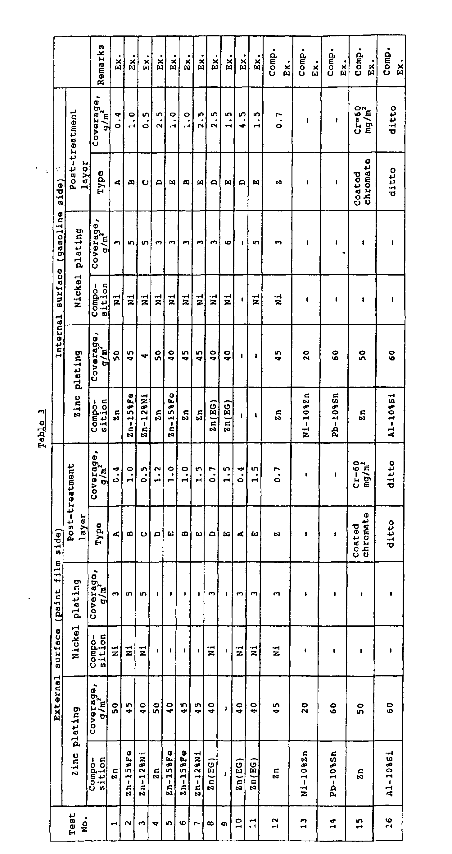
- a plating and a post-treatment layer shown in Table 3 were provided on the surface of the steel sheet.
- Zn represents the deposition of a plating by galvanizing (hot dip zinc coating)
- Zn (EG) represents the deposition of a plating by electrogalvanizing
- Zn-15%Fe represents the deposition of a plating by alloyed galvanizing
- Zn-12%Ni represents the deposition of a plating by electrolytic zinc-nickel alloy plating
- Ni represents the deposition of a plating by electrolytic nickel plating.
- Test pieces were extracted from steel sheets, on which various platings and post-treatment layers had been deposited, and were subjected to various tests. Specifically, a chromium(VI) elution test, a paint film durability test, an anti-corrosion test for gasoline, a formability test, and a weldability test were carried out by the following methods. The results are shown in Table 4.
- test piece was taken off so that the total surface area of the post-treatment layer was 300 cm 2 .
- the test piece was immersed in 500 cc of pure water which was then heated and boiled and kept in this state for 30 min. Thereafter, water in an amount lost by the evaporation was added to again bring the volume of the water to 500 cc, followed by coloring analysis of the water to determine chromium(VI) by a diphenylcarbazide method.
- a test piece having a size of 150 cm x 50 cm was extracted by cutting.
- a melamine alkyd resin-based paint free from chromium(VI) as a pigment was coated to a thickness of 20 ⁇ m, and the coating was dried, followed by a corrosion resistance test, a water resisting adhesion test, and an impact resistance test.
- test piece was immersed in pure water of 40°C for 120 hr. Thereafter, grid-like slashes were provided at intervals of 1 mm, followed by a tape peel test. The results were evaluated according to the following criteria.
- the test piece was horizontally fixed, and a 500-g steel weight having a head diameter of 6.3 mm ⁇ was repeatedly gravity dropped ten times from a height of 20 cm to determine the number of separated coating pieces.
- the results were evaluated according to the following criteria.
- the test piece was punched to form a circular plate.
- the circular plate was formed into a cylinder having an inner diameter of 50 mm and a depth of 35 mm so that one side described as internal surface in Table 3 constituted the internal surface (gasoline side).
- the inside of the cylinder was filled with any one of the following two corrosion test liquids, and the cylinder was hermetically sealed and, in this state, was kept at 30°C for 2 months.
- test piece was punched to form a 180- ⁇ circular plate which was then formed into a cylinder using a punch having a head diameter of 40 mm and a die provided with lock beads at an ear pressing pressure of 20 kN to determine the forming height.
- the results were evaluated according to the following criteria.
- Two test pieces were put on top of each other so that the internal surface in one of the test pieces faced the internal surface in the other test -piece, and seam welding was carried out using a copper electrode.
- the welding current was 20 kA
- the welding speed was 3 m/min
- the welding length was 50 cm.
- the bead portion was subjected to X-ray inspection for flaws. As a result, for all the samples shown in Table 1, cracking was not observed.
- test Nos. 1 to 11 which are examples of the present invention wherein a zinc plating, a nickel plating, and a post-treatment layer were provided on at least one side of the steel sheet, elution of chromium(VI) did not occur, the external surface had excellent durability of a paint film, and the internal surface had excellent corrosion resistance to gasoline, and the formability was also good.
- the inside of the automobile fuel containers was filled with the above corrosion test liquid 1 or 2, and the automobile fuel containers were then exposed to an environment of a place along the sea in Okinawa for one year to examine the corrosion resistance of a paint film on the external surface and the corrosion resistance of the internal surface to gasoline.
- the results were evaluated according to the following criteria. The results of evaluation are shown in Table 5.
- the automobile fuel container material and automobile fuel container possessing excellent environmental adaptability according to the present invention are good in workability, corrosion resistance of internal surface and external surface, and weldability, and are free from elution of harmful components such as lead and chromium(VI). Further, the adoption of a plating composed mainly of zinc, which is more inexpensive than aluminum and tin, as the first layer can realize mass production of automobile fuel container materials and automobile fuel containers at low cost.
- the present invention is very useful from the viewpoint of industry.
Landscapes
- Chemical & Material Sciences (AREA)
- Chemical Kinetics & Catalysis (AREA)
- Engineering & Computer Science (AREA)
- Materials Engineering (AREA)
- Mechanical Engineering (AREA)
- Metallurgy (AREA)
- Organic Chemistry (AREA)
- Other Surface Treatments For Metallic Materials (AREA)
- Cooling, Air Intake And Gas Exhaust, And Fuel Tank Arrangements In Propulsion Units (AREA)
- Containers Having Bodies Formed In One Piece (AREA)
- Laminated Bodies (AREA)
- Chemical Treatment Of Metals (AREA)
Abstract
Description




Claims (14)
- An automobile fuel container material having improved environmental adaptability, characterized by comprising:a steel sheet;a zinc plating as a first layer provided at a coverage of 5 to 80 g/m2 on at least one side of the surface of the steel sheet;a nickel plating as a second layer provided at a coverage of not more than 10 g/m2 on the zinc-plating as the first layer; anda post-treatment layer as a third layer provided at a coverage of not more than 5 g/m2 on the nickel plating as the second layer, the post-treatment layer having been formed by coating using partially reduced chromic acid and a reducing organic compound as essential components, the amount of the reducing organic compound being not less than the reduction equivalent of chromium(VI) in the partially reduced chromic acid.
- An automobile fuel container material having improved environmental adaptability, characterized by comprising:a steel sheet;a zinc plating as a first layer provided at a coverage of 5 to 80 g/m2 on at least one side of the surface of-the steel sheet;a nickel plating as a second layer provided at a coverage of not more than 10 g/m2 on the zinc plating as the first layer; anda post-treatment layer as a third layer provided at a coverage of not more than 5 g/m2 on the nickel plating as the second layer, the post-treatment layer having a structure comprising an electrolytic chromate film as a lower layer and a resin as an upper layer.
- The automobile fuel container material having improved environmental adaptability according to claim 1 or 2, characterized in that the zinc plating as the first layer is a plating of a zinc-iron alloy having an iron content of not more than 25% by weight.
- The automobile fuel container material having improved environmental adaptability according to claim 1 or 2, characterized in that the zinc plating as the first layer is a plating of a zinc-nickel alloy having a nickel content of not more than 25% by weight.
- The automobile fuel container material having improved environmental adaptability according to any one of claims 1 to 4, characterized in that the first, second, and third layers are provided on both sides of the steel sheet.
- The automobile fuel container material having improved environmental adaptability according to any one of claims 1 to 4, characterized in that the first, second, and third layers are provided on only one side of the steel sheet.
- The automobile fuel container material having improved environmental adaptability according to claim 6, characterized in that the steel sheet has, on its side remote from the first, second, and third layers, a zinc plating as a first layer provided at a coverage of 5 to 80 g/m2 and a post-treatment layer as a second layer provided at a coverage of 0.1 to 5 g/m2 on the zinc plating as the first layer.
- The automobile fuel container material having improved environmental adaptability according to claim 6, wherein the steel sheet has, on its side remote from the first, second, and third layers, a plating of a zinc-iron alloy having an iron content of not more than 25% by weight of iron as a first layer provided at a coverage of 5 to 80 g/m2 and a post-treatment layer as a second layer provided at a coverage of 0.1 to 5 g/m2 on the zinc-iron alloy plating as the first layer.
- The automobile fuel container material having improved environmental adaptability according to claim 6, characterized in that the steel sheet has, on its side remote from the first, second, and third layers, a plating of a zinc-nickel alloy having a nickel content of not more than 25% by weight of nickel as a first layer provided at a coverage of 5 to 80 g/m2 and a post-treatment layer as a second layer provided at a coverage of 0.1 to 5 g/m2 on the zinc-nickel alloy plating as the first layer.
- The automobile fuel container material having improved environmental adaptability according to claim 6, characterized in that the steel sheet has, on its side remote from the first, second, and third layers, a nickel plating provided at a coverage of not more than 10 g/m2 and a post-treatment layer provided at a coverage of 0.1 to 5 g/m2 on the nickel plating.
- The automobile fuel container material having improved environmental adaptability according to claim 6, characterized in that the steel sheet has, on its side remote from the first, second, and third layers, a post-treatment layer provided at a coverage of 0.1 to 5 g/m2.
- The automobile fuel container material having improved environmental adaptability according to any one of claims 7 to 11, characterized in that the post-treatment layer provided on the surface of the steel sheet remote from the first, second, and third layers has been formed by coating using partially reduced chromic acid and a reducing organic compound as essential components, the amount of the reducing organic compound being not less than the reduction equivalent of chromium(VI) in the partially reduced chromic acid.
- The automobile fuel container material having improved environmental adaptability according to any one of claims 7 to 11, characterized in that the post-treatment layer provided on the surface of the steel sheet remote from the first, second, and third layers has a structure comprising an electrolytic chromate film as a lower layer and a resin as an upper layer.
- An automobile fuel container characterized by being formed of the automobile fuel container material having improved environmental adaptability according to any one of claims 1 to 13.
Applications Claiming Priority (3)
| Application Number | Priority Date | Filing Date | Title |
|---|---|---|---|
| JP2000140024A JP4072304B2 (en) | 2000-05-12 | 2000-05-12 | Environmentally compatible automotive fuel container material and automotive fuel container |
| JP2000140024 | 2000-12-05 | ||
| PCT/JP2001/003983 WO2001086020A1 (en) | 2000-05-12 | 2001-05-14 | Automobile fuel container material excellent in environment compatibility and automobile fuel container |
Publications (2)
| Publication Number | Publication Date |
|---|---|
| EP1288334A1 true EP1288334A1 (en) | 2003-03-05 |
| EP1288334A4 EP1288334A4 (en) | 2006-10-25 |
Family
ID=18647381
Family Applications (1)
| Application Number | Title | Priority Date | Filing Date |
|---|---|---|---|
| EP01930102A Withdrawn EP1288334A4 (en) | 2000-05-12 | 2001-05-14 | MATERIAL FOR AUTOMOBILE TANK WITH EXCELLENT ENVIRONMENTAL COMPATIBILITY AND AUTOMOTIVE TANK |
Country Status (5)
| Country | Link |
|---|---|
| US (1) | US6866944B2 (en) |
| EP (1) | EP1288334A4 (en) |
| JP (1) | JP4072304B2 (en) |
| KR (1) | KR100506135B1 (en) |
| WO (1) | WO2001086020A1 (en) |
Cited By (1)
| Publication number | Priority date | Publication date | Assignee | Title |
|---|---|---|---|---|
| WO2010056386A1 (en) * | 2008-11-14 | 2010-05-20 | Enthone Inc. | Method for the post-treatment of metal layers |
Families Citing this family (9)
| Publication number | Priority date | Publication date | Assignee | Title |
|---|---|---|---|---|
| JP4354140B2 (en) * | 2000-12-04 | 2009-10-28 | フタバ産業株式会社 | Manufacturing method of fuel inlet |
| JP2003021012A (en) * | 2001-07-10 | 2003-01-24 | Futaba Industrial Co Ltd | Fuel tank and producing method thereof |
| US7291401B2 (en) * | 2001-09-05 | 2007-11-06 | Usui Kokusai Sangyo Kabushiki Kaisha, Ltd. | Non-hexavalent-chromium type corrosion resistant coating film structure having a resin layer and a metal layer that is superior in terms of adhesion to the resin layer |
| JP2006192919A (en) * | 2005-01-11 | 2006-07-27 | Fts:Kk | Fuel tank for automobile and manufacturing method thereof |
| US20070235458A1 (en) * | 2006-04-10 | 2007-10-11 | Mann & Hummel Gmbh | Modular liquid reservoir |
| US8613543B2 (en) * | 2007-12-13 | 2013-12-24 | Mcneilus Truck And Manufacturing, Inc. | Under drum water tank |
| KR20150071947A (en) * | 2013-12-19 | 2015-06-29 | 현대자동차주식회사 | Earth bolt containing surface treatment layer and surface treatment method of earth bolt |
| BR102014017286A2 (en) * | 2014-07-14 | 2016-02-16 | Aethra Sistemas Automotivos Sa | fuel tank manufacturing process in medium or high strength steel plates with organo-metallic coating, flanged edges and inlet pipes, spiked vent and vent |
| KR101696115B1 (en) | 2015-12-22 | 2017-01-13 | 주식회사 포스코 | Zinc-plated steel sheet having aftertreating film and aftertreating method thereof |
Family Cites Families (21)
| Publication number | Priority date | Publication date | Assignee | Title |
|---|---|---|---|---|
| US3935035A (en) * | 1973-06-05 | 1976-01-27 | Nippon Steel Corporation | Aqueous solution and method for surface treatment of metals |
| US4341564A (en) * | 1980-11-26 | 1982-07-27 | Louis Schiffman | Corrosion inhibitive pigment |
| JPS6227587A (en) * | 1985-07-29 | 1987-02-05 | Sumitomo Metal Ind Ltd | Double-plated steel sheet having ni playing for fuel vessel |
| JPS6237792A (en) * | 1985-08-10 | 1987-02-18 | Tokyo Keisuu Kogyo Kk | Resetting device for counter |
| EP0274543B1 (en) * | 1986-07-14 | 1992-10-21 | Nihon Parkerizing Co., Ltd. | Composition for treating metal surface and treating process |
| DE69109928T2 (en) * | 1990-04-20 | 1996-02-08 | Sumitomo Metal Ind | Improved, corrosion-resistant, surface-coated steel sheet. |
| JPH0474872A (en) | 1990-07-16 | 1992-03-10 | Sumitomo Metal Ind Ltd | Organic composite coated steel sheet having excellent corrosion resistance |
| DE69511250T2 (en) * | 1994-12-08 | 2000-02-03 | Sumitomo Metal Industries, Ltd. | SURFACE TREATED STEEL SHEET FOR FUEL TANKS |
| US5827618A (en) * | 1995-03-28 | 1998-10-27 | Nippon Steel Corporation | Rust-proofing steel sheet for fuel tanks and production method thereof |
| JP2964943B2 (en) * | 1996-03-06 | 1999-10-18 | 住友金属工業株式会社 | Surface treated steel sheet for fuel tank |
| KR100318649B1 (en) * | 1996-06-06 | 2002-02-19 | 고지마 마따오 | Surface-treated steel sheet excellent in corrosion resistance after working |
| AU718855B2 (en) * | 1996-07-31 | 2000-04-20 | Nippon Steel Corporation | Rustproof steel sheet for automobile fuel tank with excellent resistance weldability corrosion resistance and press moldability |
| JPH10183368A (en) | 1996-10-30 | 1998-07-14 | Nippon Steel Corp | Rustproof steel plate for fuel tanks with excellent weldability and corrosion resistance |
| JPH11269663A (en) * | 1998-01-22 | 1999-10-05 | Nippon Steel Corp | Surface treated steel sheet for fuel containers with excellent corrosion resistance and workability |
| JPH11269665A (en) * | 1998-01-22 | 1999-10-05 | Nippon Steel Corp | Surface treated steel sheet for fuel containers with excellent corrosion resistance and workability |
| JPH11310897A (en) * | 1998-04-28 | 1999-11-09 | Nippon Steel Corp | Surface treated steel sheet for fuel tank |
| JP2000008176A (en) | 1998-06-25 | 2000-01-11 | Nippon Steel Corp | Steel plates for fuel containers with excellent resistance weldability and corrosion resistance after painting |
| JP3497413B2 (en) * | 1998-07-30 | 2004-02-16 | 新日本製鐵株式会社 | Surface treated steel sheet for fuel containers with excellent corrosion resistance, workability and weldability |
| US6387538B1 (en) * | 1998-12-01 | 2002-05-14 | Pohang Iron & Steel Co., Ltd. | Surface-treated steel sheet for fuel tanks and method of fabricating same |
| KR20010048280A (en) * | 1999-11-26 | 2001-06-15 | 이구택 | Manufacturing method of chromated hot-dip galvanized steel sheet which has excellent corrosion and fuel resistance after forming for automobile fuel tank |
| AR030621A1 (en) * | 2000-09-07 | 2003-08-27 | Nippon Steel Corp | STEEL SHEET COVERED WITH A BASE BASE OR ALUMINUM BASED, SURFACE TREATED WITH A CHROME-FREE SURFACE TREATMENT AGENT HEXAVALENT. |
-
2000
- 2000-05-12 JP JP2000140024A patent/JP4072304B2/en not_active Expired - Fee Related
-
2001
- 2001-05-14 WO PCT/JP2001/003983 patent/WO2001086020A1/en not_active Ceased
- 2001-05-14 US US10/275,888 patent/US6866944B2/en not_active Expired - Lifetime
- 2001-05-14 KR KR10-2002-7014892A patent/KR100506135B1/en not_active Expired - Fee Related
- 2001-05-14 EP EP01930102A patent/EP1288334A4/en not_active Withdrawn
Cited By (3)
| Publication number | Priority date | Publication date | Assignee | Title |
|---|---|---|---|---|
| WO2010056386A1 (en) * | 2008-11-14 | 2010-05-20 | Enthone Inc. | Method for the post-treatment of metal layers |
| EP2189553A1 (en) * | 2008-11-14 | 2010-05-26 | Enthone, Inc. | Method for the post-treatment of metal layers |
| CN102282296B (en) * | 2008-11-14 | 2014-10-15 | 恩索恩公司 | Method for the post-treatment of metal layers |
Also Published As
| Publication number | Publication date |
|---|---|
| KR100506135B1 (en) | 2005-08-05 |
| JP4072304B2 (en) | 2008-04-09 |
| KR20030014215A (en) | 2003-02-15 |
| WO2001086020A1 (en) | 2001-11-15 |
| US20040089666A1 (en) | 2004-05-13 |
| JP2001323388A (en) | 2001-11-22 |
| US6866944B2 (en) | 2005-03-15 |
| EP1288334A4 (en) | 2006-10-25 |
Similar Documents
| Publication | Publication Date | Title |
|---|---|---|
| JP3497413B2 (en) | Surface treated steel sheet for fuel containers with excellent corrosion resistance, workability and weldability | |
| KR100346857B1 (en) | Steel plate for highly corrosion-resistant fuel | |
| AU2001284461B2 (en) | Hexavalent chromium-free surface-treating agent for Sn- or Al-based coated steel sheet, and surface treated steel sheet | |
| JP3800928B2 (en) | Steel plate for high corrosion resistant fuel tank | |
| US10688755B2 (en) | Steel sheet for a fuel tank | |
| US6866944B2 (en) | Automobile fuel container material excellent in environment compatibility and automobile fuel container | |
| AU718855B2 (en) | Rustproof steel sheet for automobile fuel tank with excellent resistance weldability corrosion resistance and press moldability | |
| EP0210302B1 (en) | Tinned steel sheet having a high degree of corrosion resistance and a method of producing the same | |
| JP3485457B2 (en) | Corrosion-resistant steel plates for fuel tanks with excellent corrosion resistance and weldability | |
| CN111989419B (en) | Hot-dip Sn-Zn alloy-plated steel sheet and method for producing same | |
| JP2004169122A (en) | Steel plate for zinc-based fuel containers | |
| JPS61246058A (en) | High corrosion-resistant coated steel plate for fuel vessel | |
| Kurosaki et al. | Pb-free coated steel sheet for fuel tanks | |
| JPS64474B2 (en) | ||
| KR101931046B1 (en) | Surface-treated steel sheet for fuel tank | |
| JPS61270389A (en) | Steel sheet for fuel vessel | |
| JP2957356B2 (en) | High performance fuel tank materials | |
| JPH11269665A (en) | Surface treated steel sheet for fuel containers with excellent corrosion resistance and workability | |
| JPH09324284A (en) | Surface-treated steel sheet with excellent corrosion resistance after processing | |
| JPH11269663A (en) | Surface treated steel sheet for fuel containers with excellent corrosion resistance and workability | |
| JPH10278172A (en) | High corrosion resistant steel plate for fuel tank | |
| JPS61266596A (en) | Steel sheet for fuel container | |
| JPH10265964A (en) | High corrosion resistant surface treated steel plate for fuel container | |
| JPS61270390A (en) | Steel sheet for fuel vessel | |
| JPH10278173A (en) | High corrosion resistant steel plate for fuel tank |
Legal Events
| Date | Code | Title | Description |
|---|---|---|---|
| PUAI | Public reference made under article 153(3) epc to a published international application that has entered the european phase |
Free format text: ORIGINAL CODE: 0009012 |
|
| 17P | Request for examination filed |
Effective date: 20021211 |
|
| AK | Designated contracting states |
Designated state(s): AT BE CH CY DE DK ES FI FR GB GR IE IT LI LU MC NL PT SE TR Kind code of ref document: A1 Designated state(s): AT BE CH CY DE DK ES FI FR GB GR IE IT LI LU MC NL PT SE TR |
|
| RAP1 | Party data changed (applicant data changed or rights of an application transferred) |
Owner name: MITSUBISHI JIDOSHA KOGYO KABUSHIKI KAISHA Owner name: NIPPON STEEL CORPORATION |
|
| RBV | Designated contracting states (corrected) |
Designated state(s): DE |
|
| A4 | Supplementary search report drawn up and despatched |
Effective date: 20060926 |
|
| RAP1 | Party data changed (applicant data changed or rights of an application transferred) |
Owner name: MITSUBISHI JIDOSHA KOGYO KABUSHIKI KAISHA Owner name: NIPPON STEEL CORPORATION |
|
| 17Q | First examination report despatched |
Effective date: 20071109 |
|
| GRAP | Despatch of communication of intention to grant a patent |
Free format text: ORIGINAL CODE: EPIDOSNIGR1 |
|
| GRAC | Information related to communication of intention to grant a patent modified |
Free format text: ORIGINAL CODE: EPIDOSCIGR1 |
|
| STAA | Information on the status of an ep patent application or granted ep patent |
Free format text: STATUS: THE APPLICATION IS DEEMED TO BE WITHDRAWN |
|
| 18D | Application deemed to be withdrawn |
Effective date: 20110521 |