EP1288326A1 - Method of producing spray deposit on bearing boss - Google Patents
Method of producing spray deposit on bearing boss Download PDFInfo
- Publication number
- EP1288326A1 EP1288326A1 EP01921811A EP01921811A EP1288326A1 EP 1288326 A1 EP1288326 A1 EP 1288326A1 EP 01921811 A EP01921811 A EP 01921811A EP 01921811 A EP01921811 A EP 01921811A EP 1288326 A1 EP1288326 A1 EP 1288326A1
- Authority
- EP
- European Patent Office
- Prior art keywords
- base material
- structural base
- thermal spray
- spray coating
- boss
- Prior art date
- Legal status (The legal status is an assumption and is not a legal conclusion. Google has not performed a legal analysis and makes no representation as to the accuracy of the status listed.)
- Granted
Links
Images


Classifications
-
- C—CHEMISTRY; METALLURGY
- C23—COATING METALLIC MATERIAL; COATING MATERIAL WITH METALLIC MATERIAL; CHEMICAL SURFACE TREATMENT; DIFFUSION TREATMENT OF METALLIC MATERIAL; COATING BY VACUUM EVAPORATION, BY SPUTTERING, BY ION IMPLANTATION OR BY CHEMICAL VAPOUR DEPOSITION, IN GENERAL; INHIBITING CORROSION OF METALLIC MATERIAL OR INCRUSTATION IN GENERAL
- C23C—COATING METALLIC MATERIAL; COATING MATERIAL WITH METALLIC MATERIAL; SURFACE TREATMENT OF METALLIC MATERIAL BY DIFFUSION INTO THE SURFACE, BY CHEMICAL CONVERSION OR SUBSTITUTION; COATING BY VACUUM EVAPORATION, BY SPUTTERING, BY ION IMPLANTATION OR BY CHEMICAL VAPOUR DEPOSITION, IN GENERAL
- C23C4/00—Coating by spraying the coating material in the molten state, e.g. by flame, plasma or electric discharge
-
- B—PERFORMING OPERATIONS; TRANSPORTING
- B23—MACHINE TOOLS; METAL-WORKING NOT OTHERWISE PROVIDED FOR
- B23P—METAL-WORKING NOT OTHERWISE PROVIDED FOR; COMBINED OPERATIONS; UNIVERSAL MACHINE TOOLS
- B23P13/00—Making metal objects by operations essentially involving machining but not covered by a single other subclass
-
- C—CHEMISTRY; METALLURGY
- C23—COATING METALLIC MATERIAL; COATING MATERIAL WITH METALLIC MATERIAL; CHEMICAL SURFACE TREATMENT; DIFFUSION TREATMENT OF METALLIC MATERIAL; COATING BY VACUUM EVAPORATION, BY SPUTTERING, BY ION IMPLANTATION OR BY CHEMICAL VAPOUR DEPOSITION, IN GENERAL; INHIBITING CORROSION OF METALLIC MATERIAL OR INCRUSTATION IN GENERAL
- C23C—COATING METALLIC MATERIAL; COATING MATERIAL WITH METALLIC MATERIAL; SURFACE TREATMENT OF METALLIC MATERIAL BY DIFFUSION INTO THE SURFACE, BY CHEMICAL CONVERSION OR SUBSTITUTION; COATING BY VACUUM EVAPORATION, BY SPUTTERING, BY ION IMPLANTATION OR BY CHEMICAL VAPOUR DEPOSITION, IN GENERAL
- C23C4/00—Coating by spraying the coating material in the molten state, e.g. by flame, plasma or electric discharge
- C23C4/01—Selective coating, e.g. pattern coating, without pre-treatment of the material to be coated
-
- F—MECHANICAL ENGINEERING; LIGHTING; HEATING; WEAPONS; BLASTING
- F16—ENGINEERING ELEMENTS AND UNITS; GENERAL MEASURES FOR PRODUCING AND MAINTAINING EFFECTIVE FUNCTIONING OF MACHINES OR INSTALLATIONS; THERMAL INSULATION IN GENERAL
- F16C—SHAFTS; FLEXIBLE SHAFTS; ELEMENTS OR CRANKSHAFT MECHANISMS; ROTARY BODIES OTHER THAN GEARING ELEMENTS; BEARINGS
- F16C11/00—Pivots; Pivotal connections
- F16C11/04—Pivotal connections
- F16C11/045—Pivotal connections with at least a pair of arms pivoting relatively to at least one other arm, all arms being mounted on one pin
-
- F—MECHANICAL ENGINEERING; LIGHTING; HEATING; WEAPONS; BLASTING
- F16—ENGINEERING ELEMENTS AND UNITS; GENERAL MEASURES FOR PRODUCING AND MAINTAINING EFFECTIVE FUNCTIONING OF MACHINES OR INSTALLATIONS; THERMAL INSULATION IN GENERAL
- F16C—SHAFTS; FLEXIBLE SHAFTS; ELEMENTS OR CRANKSHAFT MECHANISMS; ROTARY BODIES OTHER THAN GEARING ELEMENTS; BEARINGS
- F16C2350/00—Machines or articles related to building
- F16C2350/26—Excavators
-
- Y—GENERAL TAGGING OF NEW TECHNOLOGICAL DEVELOPMENTS; GENERAL TAGGING OF CROSS-SECTIONAL TECHNOLOGIES SPANNING OVER SEVERAL SECTIONS OF THE IPC; TECHNICAL SUBJECTS COVERED BY FORMER USPC CROSS-REFERENCE ART COLLECTIONS [XRACs] AND DIGESTS
- Y10—TECHNICAL SUBJECTS COVERED BY FORMER USPC
- Y10T—TECHNICAL SUBJECTS COVERED BY FORMER US CLASSIFICATION
- Y10T29/00—Metal working
- Y10T29/49—Method of mechanical manufacture
- Y10T29/49636—Process for making bearing or component thereof
- Y10T29/49643—Rotary bearing
- Y10T29/49647—Plain bearing
- Y10T29/49668—Sleeve or bushing making
- Y10T29/49677—Sleeve or bushing making having liner
-
- Y—GENERAL TAGGING OF NEW TECHNOLOGICAL DEVELOPMENTS; GENERAL TAGGING OF CROSS-SECTIONAL TECHNOLOGIES SPANNING OVER SEVERAL SECTIONS OF THE IPC; TECHNICAL SUBJECTS COVERED BY FORMER USPC CROSS-REFERENCE ART COLLECTIONS [XRACs] AND DIGESTS
- Y10—TECHNICAL SUBJECTS COVERED BY FORMER USPC
- Y10T—TECHNICAL SUBJECTS COVERED BY FORMER US CLASSIFICATION
- Y10T29/00—Metal working
- Y10T29/49—Method of mechanical manufacture
- Y10T29/49636—Process for making bearing or component thereof
- Y10T29/49705—Coating or casting
-
- Y—GENERAL TAGGING OF NEW TECHNOLOGICAL DEVELOPMENTS; GENERAL TAGGING OF CROSS-SECTIONAL TECHNOLOGIES SPANNING OVER SEVERAL SECTIONS OF THE IPC; TECHNICAL SUBJECTS COVERED BY FORMER USPC CROSS-REFERENCE ART COLLECTIONS [XRACs] AND DIGESTS
- Y10—TECHNICAL SUBJECTS COVERED BY FORMER USPC
- Y10T—TECHNICAL SUBJECTS COVERED BY FORMER US CLASSIFICATION
- Y10T29/00—Metal working
- Y10T29/49—Method of mechanical manufacture
- Y10T29/49636—Process for making bearing or component thereof
- Y10T29/49707—Bearing surface treatment
-
- Y—GENERAL TAGGING OF NEW TECHNOLOGICAL DEVELOPMENTS; GENERAL TAGGING OF CROSS-SECTIONAL TECHNOLOGIES SPANNING OVER SEVERAL SECTIONS OF THE IPC; TECHNICAL SUBJECTS COVERED BY FORMER USPC CROSS-REFERENCE ART COLLECTIONS [XRACs] AND DIGESTS
- Y10—TECHNICAL SUBJECTS COVERED BY FORMER USPC
- Y10T—TECHNICAL SUBJECTS COVERED BY FORMER US CLASSIFICATION
- Y10T29/00—Metal working
- Y10T29/49—Method of mechanical manufacture
- Y10T29/4981—Utilizing transitory attached element or associated separate material
- Y10T29/49812—Temporary protective coating, impregnation, or cast layer
-
- Y—GENERAL TAGGING OF NEW TECHNOLOGICAL DEVELOPMENTS; GENERAL TAGGING OF CROSS-SECTIONAL TECHNOLOGIES SPANNING OVER SEVERAL SECTIONS OF THE IPC; TECHNICAL SUBJECTS COVERED BY FORMER USPC CROSS-REFERENCE ART COLLECTIONS [XRACs] AND DIGESTS
- Y10—TECHNICAL SUBJECTS COVERED BY FORMER USPC
- Y10T—TECHNICAL SUBJECTS COVERED BY FORMER US CLASSIFICATION
- Y10T29/00—Metal working
- Y10T29/49—Method of mechanical manufacture
- Y10T29/4998—Combined manufacture including applying or shaping of fluent material
- Y10T29/49982—Coating
- Y10T29/49986—Subsequent to metal working
Definitions
- This invention relates to a method for manufacturing a bearing boss with a thermal spray coating layer, which can be suitably used, for example, at a pivotal pin joint portion of a working mechanism of a construction machine or the like.
- construction machines such as hydraulic power shovel type excavator machines, for example, are equipped with a working mechanism for ground excavating operations or for performing other ground working jobs.
- the working mechanisms of this sort generally have a boom, an arm and a bucket which are pivotally connected with each other through a bearing device.
- a boss is provided at a fore end of an arm, which is one of two members to be pivotally connected to each other, while a pair of brackets are provided on the part of a bucket or the other one of the two members to be pivotally connected.
- the boss is fitted between the paired brackets, and pivotally connected to the latter by the use of a joint pin.
- a bush is fitted in a joint pin hole in the boss, and the joint pin is slidably received and supported in the bush on the inner peripheral side of the boss.
- end faces of the boss are held in sliding contact with end faces of the brackets thereby to support thrust loads, which are exerted on the bucket during an excavating operation.
- a bush is fitted in a joint pin hole on the inner peripheral side of the boss by press-in fitting for slidably supporting a joint pin therein.
- high precision machining is required in shaping a joint pin hole in the boss according to the outside diameter of the bush.
- a method for manufacturing a bearing boss with a thermal spray coating layer comprising the steps of: preparing a structural base material for a boss, the structural base material having an annular body and containing an original hole to be ultimately into a joint pin hole of a predetermined diameter; masking an end face of the structural base material on surface areas corresponding to an allowance range of a machining operation; and forming a thermal spray coating layer on unmasked surface areas on the end face of the structural base material by the use of cemented carbide material.
- an end face of an annular structural base material for a boss unit is masked as a non-coating surface area in those portions corresponding to an allowance range of a machining operation by which an original hole in the structural base material is ultimately shaped into a joint pin hole of a predetermined diameter. Accordingly, a subsequent machining operation on the original hole in the structural base material does not require to remove part of the hard thermal spray coating layer along with stock of the base material, permitting to shape the original hole into a joint pin hole of a specified diameter in a facilitated manner.
- an inner masking member is fitted in the original hole of the structural base material at the time of masking the end face thereof, and a thermal spray coating layer of a hard material is formed on an annular surface area circumventing outer periphery of the inner masking member.
- an inner masking member is fitted in an original hole in an annular structural base material for a boss unit, and in this state a thermal spray coating layer of a hard material is formed on the end face of the structural base material. Therefore, a thermal spray coating layer is formed on the end face of the structural base material only on an annular coating area which circumvents the inner masking member.
- inner and outer masking members are fitted in or on inner and outer peripheral sides of the structural base material at the time of masking the end face, and a thermal spray coating layer of a hard material is formed on the end face on an annular surface area between the inner and outer masking members.
- an inner masking member is fitted in an original hole in an annular structural material for a boss unit while an outer masking member is fitted on outer peripheral side of the structural base material, and in this state a thermal spray coating layer of a hard material is formed on the end face of the structural base material only on an annular surface area which is exposed between the inner and outer masking members.
- the inner masking member is arranged to have a masking portion with an outside diameter larger than a joint pin hole to be ultimately formed by machining an original hole in the base material.
- the inner masking member is arranged to have a masking portion with an outside diameter larger than an allowance range in a machining operation by which an original hole in the structural base material is ultimately formed into a joint pin hole of a predetermined diameter.
- the machining operation does not require to remove part of the hard thermal spray coating layer along with stock of the structural base material, and the original hole in the structural base material can be easily machined by the use of a cutting tool.
- a bearing device according to the invention is applied by way of example to a pivotal pin joint of a hydraulic power shovel type excavator.
- a lower traveling structure of an excavator and at 2 is an upper revolving structure which is rotatably mounted on the lower traveling structure 1.
- the upper revolving structure 2 is provided with a revolving frame 3.
- a cab 4 which defines an operating room and a counterweight 5 are mounted on the revolving frame 3.
- the working mechanism 6 is a working mechanism which is provided on a front portion of the upper revolving structure 2 for lifting loads up and down.
- the working mechanism 6 is largely constituted by a boom 7 which is connected to the revolving frame 3 through a pivotal pin joint, an arm 8 which is connected to a fore end portion of the boom 7 through a pivotal pin joint, and a bucket 9 which is connected to a fore end portion of the arm 8 through a pivotal pin joint.
- the boom 7 of the working mechanism 6 is lifted up and down by means a boom cylinder 10, the arm 8 is turned up and down relative to the boom 7 by an arm cylinder 11, and the bucket 9 is turned up and down relative to the arm 8 by a bucket cylinder 12.
- the bearing device 21 is largely constituted by an arm boss 22, brackets 26 and a joint pin 27 which will be described below.
- the arm boss 22 is provided on a fore end portion of the arm 8 to serve as a bearing boss, and securely welded to fore end portions of upper and lower flanges 8A and to right and left webs 8B of the arm 8 (Fig. 10).
- the arm boss 22 is constituted by a pair of right and left boss units 23 which are located in axially spaced positions, and a bridge ring 24 which connects the right and left boss units 23 securely to each other.
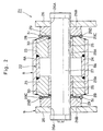
- the boss units 23 are each in the form of an annular ring of cast iron or other metallic material, and are securely welded to the opposite ends of the bridge ring 24 in fitting engagement with the latter. Further, the boss units 23 are each provided with a joint pin hole 23A of a predetermined diameter, for example, of approximately 95mm in inside diameter. As seen particularly in Fig. 3, the boss units 23 are each provided with an end face 23B on an axially outer side in confronting relation with a bracket 26. The end face 23B is provided with an annular tapered surface 23C at and around its outer marginal edges.
- each boss unit 23 is provided with a coating surface area 23B1 to be coated with a thermal spray coating layer 28, which will be described hereinafter, and an inner non-coating surface area 23B2 radially inward of the coating surface area 23B1. Thrust loads which are exerted on the bucket 9 during an excavating operation of the hydraulic power shovel are supported by end faces 26C of the brackets 26 through the thermal spray coating layers 28 and 29.
- Indicated at 25 are a pair of bushes which are fitted in joint pin holes 23A in the respective boss units 23 of the arm boss 22.
- Each one of the bushes 25 is formed of a sintered alloy or the like and in a cylindrical shape, and set in the joint pin hole 23A of the boss unit 23 by press-in fitting.
- Brackets 26 are right and left brackets which are provided in laterally spaced positions on the bucket 9. These brackets 26 are each in the form of a flat plate of steel or other metal material and located in face to face relation with each other in the axial direction of the arm boss 22. Further, the brackets 26 are each provided with a joint pin hole 26A axially in alignment with the joint pin holes 23A of the boss units 23.
- annular reinforcing member 26B is securely welded to the inner side of each bracket 26 axially in alignment with the arm boss 22. As shown in Fig. 3, on the side of the boss unit 23, the reinforcing member 26B is provided with an annular end face 26C in coaxially aligned relation with the boss unit 23. The end face 26C of the bracket 26 is provided with an annular tapered surface 26D at and around its outer marginal edges.
- a joint pin which has its axially intermediate portion fitted in the bush 25 and its axially opposite end portions fitted in the joint pin holes 26A of the brackets 26 to support the arm boss 22 rotatably between the brackets 26.
- a left end portion of the joint pin 27 is non-rotatably fixed to the left one of the brackets 26 through an anti-rotational stopper mechanism (not shown).
- a lubricant such as grease is filled in the internal space between the bridge ring 24 of the arm boss 22 and the joint pin 27 in a sealed state thereby to lubricate sliding surfaces of the bush 25 and the joint pin 27.
- the thermal spray coating layers 28 are formed by thermal spraying a cemented carbide material with high rigidity and thermal resistance.
- the cemented carbide material contains powder of nickel and chromium along with tungsten carbide and thermal sprayed by means of a plasma spraying method or by a high energy spraying method.
- the powder of the cemented carbide material is composed of, for example, 70-90 wt% of tungsten carbide, and 10-30 wt% of nickel and chromium in a total amount.
- thermal spray coating layers which are formed by thermal spraying a hard material on the end faces 26C of the right and left brackets 26.
- the thermal spray coating layers 29 are formed by the use of a cemented carbide material as mentioned above.
- Both of the thermal spray coating layers 28 and 29 constitute wear proof layers which prevent abrasive wear of or damages to end faces 23B and 26C of the arm boss 22 and brackets 26 which are held in direct sliding contact with each other as the bucket 9 is turned up and down.
- Dust seal rings which are fitted in the joint pin holes 23A of the boss units 23 on the outer side of the arm boss 22. These dust seal rings 30 serve to prevent dirt or other foreign matter from getting between sliding surfaces of the bushes 25 and the joint pin 27, and at the same time to distribute part of grease, which has been supplied to the just-mentioned sliding surfaces, toward the thermal spray coating layers 28 and 29 of the arm boss 22 and brackets 26.
- O-rings which are fitted on to seal gaps between the arm boss 22 and the brackets 26.
- Each one of the O-rings 31 is fitted across a gap between the tapered surface 23C and 26D of the arm boss 23 and a bracket 26 with a predetermined degree of interference to prevent foreign matter from getting between the arm boss 22 and the bracket 26.
- the bucket cylinder 12 is stretched out or contracted to turn the brackets 26 relative to the arm boss 22 through the joint pin 27.
- the bucket 9 at the fore end of the arm 8 is turned up and down to excavate earth out of a ground.
- a structural base material 23' for the boss unit 23 is prepared from cast iron material.
- the structural base material 23' which is an original structural base material for a boss unit 23, includes an original hole 23A', end face 23B' and tapered surface 23C' of approximately predetermined dimensions.
- the structural base material 23' for a boss unit 23 contains an original hole 23A' to be machined into the joint pin hole 23A in a later stage.
- the original hole 23A' has a diameter D of approximately 85mm.
- Fig. 7 there is shown a masking stage in which, except the coating surface area 23B1', the end face 23B' of the structural base material 23' is masked by the use of an inner masking member 32 in the form of a stepped cylinder with a flange and an outer masking member 33 in the shape of a ring with an annular bottom portion.
- the end face 23B' of the latter is masked by the masking member 32 at radially inner surface areas which correspond to the machining allowance ⁇ D and marginal surface areas which circumvent the machining allowance range ⁇ D.
- the inside diameter d2 of the structural base material 23' corresponds to the diameter of a border between the end face 23B' and the annular tapered surface 23C' on the side of the structural base material 23'.
- outer peripheral surfaces of the structural base material 23' is masked by the outer masking member 33, including the tapered surface 23C'.
- the end face 23B' of the structural base material 23' is masked except the coating surface area 23B1 which is exposed between the outer diameter d1 of the inner masking member 32 and the inside diameter d2 of the outer masking member 33.
- a thermal spray coating layer 28 is formed on the coating surface area 23B1' on the end face 23B' of the structural base material 23' between the inner and outer masking members 32 and 33 by thermal spraying a cemented carbide material which contains tungsten carbide as a major component, as indicated by an arrow in Fig. 8.
- the cemented carbide material is coated only on the coating surface area 23B1' of the end face 23B' of the structural base material 23', leaving uncoated or exposed other surface areas including the inner non-coating surface area 23B2' which is provided around the original joint pin hole and radially inward of the coating surface area 23B1'.
- thermal spray coating stage is a first welding stage as shown in Fig. 9, in which a couple of structural base materials 23', each with a thermal spray coating layer 28, are welded to each other by welding them to the opposite ends of a bridge ring 24 to make an arm boss 22'.
- a second welding stage shown in Fig. 10 the arm boss 22' is welded to fore end portions of upper and lower flanges 8A and right and left webs 8B of an arm 8.
- the original holes 23A' in the structural base material 23' of the boss 22, which is welded to the arm 8 are each machined to a specified diameter by the use of a cutting tool, removing the stock of the structural base material 23' to an extent corresponding to the machining margin or a machining allowance range ⁇ D and thereby shaping each one of the original holes 23A' into a joint pin hole 23A of a predetermined diameter as indicated by one-dot chain line in Fig. 10. Accordingly, the arm boss now has the machined joint pin hole 23A in the same manner as in Fig. 2 except that it is not yet assembled with the bushes 25, brackets 26 and joint pin 27.
- the end face 23B' of each unit of structural base material 23' is provided with a non-coating surface area 23B2' around the original hole approximately in a breadth corresponding to the machining allowance range ⁇ D. Therefore, at the time of machining the original hole 23A' into the joint pin hole 23A by the use of a cutting tool in the final machining stage, there is no necessity for removing part of the thermal spray coating layer 28 which is harder than the structural base body 23'. Namely, the original hole 23A' be machined into a joint pin hole 23A of a specified diameter quite easily by the use of a cutting tool.
- the original hole 23A' in the structural base material or base body 23' can be machined free of cracking or exfoliation troubles which would otherwise occur to the thermal spray coating layer 28 as explained hereinbefore in connection with the prior art.
- This of course makes it possible to enhance the performance quality and reliability of the thermal spray coating layers 28.
- the service life of the cutting tool can be prolonged to a marked degree because there is no need any more for removing part of hard coated layers of cemented carbide layer.
- the inner non-coating surface area 23B2 on the end face 23B of the structural base material 23' is arranged to have a breadth which includes outer marginal portions of the machining allowance range ⁇ D. Therefore, even in a case where a tolerance is set at a relatively large value in machining the original hole 23A', the machining operation can be completed without necessitating to remove part of the thermal spray coating layer 28 along with the stock of the structural base material 23A' to preclude the possibilities of cracking of the thermal spray coating layer 28.
- the structural base bodies 23' are welded to the bridge ring 24 and arm 8 before machining the original holes 23A'. Therefore, even if a structural base material 23' is dropped and damaged on the side of its original hole 23A', damaged portions can be removed in the following machining stage to provide a joint pin hole 23A with smooth finished surfaces.
- the inner and outer masking members 32 and 33 are fitted on the inner and outer peripheral sides of a structural base material 23' in the masking stage. Namely, except the coating surface area 23B1', the end face 23B' of the structural base material 23' can be masked simply by fitting two masking members in or on the structural base material 23', easily in an efficient manner as compared with masking by the use of masking tapes or the like.
- the arm boss 22 of the bearing device 21 is constituted by a couple of boss units 23 and one bridge ring 24.
- the present invention is not limited to this particular form of arm boss.
- an arm boss 42 of a bearing device 41 may be constituted by a single boss unit 42 with a thermal spray coating layer 28 of cemented carbide on each end face.
- the arm boss 42 of the first modification is provided with joint pin holes 42A and tapered surfaces 42B.
- the present embodiment employs the inner and outer masking members 32 and 33 which are adapted to fit in or on the inner and outer peripheral sides of a structural base material 23' for a boss unit.
- the outer masking member 33 can be dispensed with as in a second modification shown in Fig. 12.
- a thermal spray coating layer 28' of cemented carbide can be formed on an annular coating surface area 23B1' on an end face 23B' of the structural base material 23', on the outer side of the inner masking member 32.
- a thermal spray coating layer 28' is formed also on a tapered surface 23C' of a coating surface area 23B1' on the end face 23B.
- cemented carbide material containing tungsten carbide as a major component is employed by way of example in forming the thermal spray coating layers 28 and 29.
- the present invention is not limited to cemented carbide material of this sort.
- the thermal spray coating layers may be formed by the use of other cemented carbide material containing molybdenum as a major component or by the use of ceramic material containing silicon carbide, titanium carbide, alumina and chromium oxide as major components.
- the bearing device of the present invention is applied to a pivotal pin joint between the arm 8 and the bucket 9 of the working mechanism in the above-described embodiments, it can be applied similarly to other pin joint portions, for example, to a pin joint portion between the boom 7 and the arm 8 or between the revolving frame 3 and the boom 7, or to other pivotal pin joint portions on hydraulic cranes or other construction machines or on other agricultural or industrial machines.
- the end face of an annular structural base material to be machined into a bearing boss is masked on a surface area falling in an allowance range of a machining operation by which an original hole in the structural base material is shaped into a joint pin hole of a predetermined diameter in a later stage subsequently to thermal spray coating the end face of the bearing boss. Accordingly, a thermal spray coating layer is not formed in a surface area corresponding to an allowance of a machining operation by which the original hole in the structural base material is shaped into a joint pin hole of a specified diameter in a later stage.
- an inner masking member prior to thermal spray coating an end face of a structural base material for a boss unit, an inner masking member is fitted in an original hole in the structural base material thereby to mask surface areas of the end face of the structural base material radially inward of an annular coating surface. Therefore, surface areas of the end face, except a predetermined coating area, can be masked simply by fitting one inner masking member in the structural base material. Thus, the masking of the structural base material can be completed efficiently and in a facilitated manner.
- an inner masking member is fitted in an original hole in the structural base material while an outer masking member is fitted on the outer peripheral side of the structural base material to mask surface areas on the end face of the structural base material which are radially on the inner and outer side of a predetermined annular coating area.
- the end face of the structural base material can also be masked easily upon fitting the inner and outer masking members on the inner and outer peripheral sides of the structural base material.
- the masking of the structural base material can also be completed efficiently and in a facilitated manner by the use of the inner and outer masking members.
- the inner masking member to be fitted in a structural base material for a boss unit is arranged to have an outside diameter which is larger than a joint pin hole which is ultimately formed by machining an original hole in the structural base material, that is, larger than an allowance range.in machining the joint pin hole. Therefore, a surface area which corresponds to the allowance range of the machining operation is left as a non-coating area free of the thermal spray coating layer. It follows that, at the time of machining an original hole in the structural base material into a final joint pin hole by the use of a cutting tool, there is no necessity for removing part of the thermal spray coating along with stock of the structural base material. That is to say, the original hole in the structural base material can be easily machined by the use of a cutting tool.
Landscapes
- Chemical & Material Sciences (AREA)
- Engineering & Computer Science (AREA)
- Mechanical Engineering (AREA)
- Materials Engineering (AREA)
- Plasma & Fusion (AREA)
- Chemical Kinetics & Catalysis (AREA)
- Physics & Mathematics (AREA)
- Metallurgy (AREA)
- Organic Chemistry (AREA)
- Coating By Spraying Or Casting (AREA)
- Component Parts Of Construction Machinery (AREA)
- Sliding-Contact Bearings (AREA)
- Physical Vapour Deposition (AREA)
Abstract
Description
- This invention relates to a method for manufacturing a bearing boss with a thermal spray coating layer, which can be suitably used, for example, at a pivotal pin joint portion of a working mechanism of a construction machine or the like.
- Generally, construction machines such as hydraulic power shovel type excavator machines, for example, are equipped with a working mechanism for ground excavating operations or for performing other ground working jobs. The working mechanisms of this sort generally have a boom, an arm and a bucket which are pivotally connected with each other through a bearing device.
- More particularly, in the case of a hydraulic power shovel type excavator, for example, a boss is provided at a fore end of an arm, which is one of two members to be pivotally connected to each other, while a pair of brackets are provided on the part of a bucket or the other one of the two members to be pivotally connected. The boss is fitted between the paired brackets, and pivotally connected to the latter by the use of a joint pin. A bush is fitted in a joint pin hole in the boss, and the joint pin is slidably received and supported in the bush on the inner peripheral side of the boss.
- Further, according to a prior art arrangement, end faces of the boss are held in sliding contact with end faces of the brackets thereby to support thrust loads, which are exerted on the bucket during an excavating operation.
- In the case of a prior art machine which is arranged to handle a large amount of soil or dirt by the bucket each time, it is inevitable that soil frequently gets into small clearances between the boss and the brackets. Rotations of the bucket in this state invariably result in accelerated abrasive wear of end faces of the boss due to abrasion by dirt.
- Regarding other prior art bearing devices of this sort, for instance, there has been known in the art a bearing device as described in Japanese Laid-Open Patent No. H9-184518. In this case, in order to enhance resistance to abrasive wear, a hard material, for example tungsten carbide, is provided on end faces of a boss which are in contact with brackets.
- In the case of the prior art just mentioned, a bush is fitted in a joint pin hole on the inner peripheral side of the boss by press-in fitting for slidably supporting a joint pin therein. In this case, however, high precision machining is required in shaping a joint pin hole in the boss according to the outside diameter of the bush.
- In this regard, according to this prior art arrangement, in order to form a joint pin hole of high precision, an original hole on the inner peripheral side of a structural base material for a boss unit is subsequently machined precisely to a specified diameter by a finish machining operation.
- However, in a case where a hard thermal spray coating layer is formed on the entire end faces of a boss in the manner as in the bearing device of the second prior art mentioned above, a number of problems arise at the time of finishing a joint pin hole in a subsequent precision machining stage, as described below.
- Namely, at the time of machining an original hole of a structural base material for a boss unit into a joint pin hole subsequently to forming thermal spray coating layers on its end faces, part of the thermal spray coating layers need to be removed along with stock of the base material depending on an allowance range in the machining operation. Upon partial removal, cracking, defoliation or other damages however are likely to occur to the hard thermal spray coating layers on the boss. In addition, there arises another problem that the service life of a cutting tool can be shortened to a considerable degree by machining the thermal spray coating layers.
- In view of the problems with the prior art devices, it is an object of the present invention to provide a method for manufacturing a bearing boss with a thermal spray coating layer, which can prevent cracking or damages as would normally occur to a thermal spray coating layer on an end face of an annular structural base material of a boss when machining an original hole in the structural base material into a final joint pin hole of a specified diameter, and which can contribute to improve the quality of the thermal spray coating layer.
- According to the present invention, in order to achieve the above-stated objective, there is provided a method for manufacturing a bearing boss with a thermal spray coating layer, comprising the steps of: preparing a structural base material for a boss, the structural base material having an annular body and containing an original hole to be ultimately into a joint pin hole of a predetermined diameter; masking an end face of the structural base material on surface areas corresponding to an allowance range of a machining operation; and forming a thermal spray coating layer on unmasked surface areas on the end face of the structural base material by the use of cemented carbide material.
- With the arrangements just described, at the time of forming a thermal spray coating layer of a hard material on an end face of a bearing boss, an end face of an annular structural base material for a boss unit is masked as a non-coating surface area in those portions corresponding to an allowance range of a machining operation by which an original hole in the structural base material is ultimately shaped into a joint pin hole of a predetermined diameter. Accordingly, a subsequent machining operation on the original hole in the structural base material does not require to remove part of the hard thermal spray coating layer along with stock of the base material, permitting to shape the original hole into a joint pin hole of a specified diameter in a facilitated manner.
- Further, according to the present invention, an inner masking member is fitted in the original hole of the structural base material at the time of masking the end face thereof, and a thermal spray coating layer of a hard material is formed on an annular surface area circumventing outer periphery of the inner masking member.
- In this case, an inner masking member is fitted in an original hole in an annular structural base material for a boss unit, and in this state a thermal spray coating layer of a hard material is formed on the end face of the structural base material. Therefore, a thermal spray coating layer is formed on the end face of the structural base material only on an annular coating area which circumvents the inner masking member.
- Further, according to the present invention, inner and outer masking members are fitted in or on inner and outer peripheral sides of the structural base material at the time of masking the end face, and a thermal spray coating layer of a hard material is formed on the end face on an annular surface area between the inner and outer masking members.
- In this case, an inner masking member is fitted in an original hole in an annular structural material for a boss unit while an outer masking member is fitted on outer peripheral side of the structural base material, and in this state a thermal spray coating layer of a hard material is formed on the end face of the structural base material only on an annular surface area which is exposed between the inner and outer masking members.
- Further, according to the present invention, the inner masking member is arranged to have a masking portion with an outside diameter larger than a joint pin hole to be ultimately formed by machining an original hole in the base material.
- Alternatively, according to the present invention, the inner masking member is arranged to have a masking portion with an outside diameter larger than an allowance range in a machining operation by which an original hole in the structural base material is ultimately formed into a joint pin hole of a predetermined diameter.
- Therefore, in a stage of machining a joint pin hole, the machining operation does not require to remove part of the hard thermal spray coating layer along with stock of the structural base material, and the original hole in the structural base material can be easily machined by the use of a cutting tool.
- In the accompanying drawings:
- Fig. 1 is an outer view of a hydraulic power shovel type excavator incorporating a bearing device according to the present invention;
- Fig. 2 is an enlarged vertical sectional view of the bearing device, taken in the direction of arrows II-II of Fig. 1;
- Fig. 3 is a fragmentary sectional view, showing on an enlarged scale an arm boss, a bracket and thermal spray coating layers in Fig. 2;
- Fig. 4 is an enlarged perspective view of the boss in a separated state;
- Fig. 5 is a left side view of the boss taken in the direction of arrows V-V in Fig. 4;
- Fig. 6 is a sectional view of a structural base material for a boss unit, obtained in a preparatory machining stage;
- Fig. 7 is a sectional view of the structural base material for a boss unit, fitted with inner and outer masking members;
- Fig. 8 is a sectional view of the annular structural base material having a thermal spray coating layer formed on one end face in a thermal spray coating stage;
- Fig. 9 is a sectional view of a couple of boss units welded to each other through a bridge ring in a first welding stage;
- Fig. 10 is a side of an arm boss welded to an arm member of a working mechanism in a second welding stage;
- Fig. 11 is a sectional view of a first modification according to the present invention, taken in the same direction as in Fig. 2; and
- Fig. 12 is a sectional view similar to Fig. 7, showing a masking stage in a second modification according to the present invention.
-
- Hereafter, the present invention is described more particularly by way of its preferred embodiments with reference to Figs. 1 through 10, in which a bearing device according to the invention is applied by way of example to a pivotal pin joint of a hydraulic power shovel type excavator.
- In the drawings, indicated at 1 is a lower traveling structure of an excavator, and at 2 is an upper revolving structure which is rotatably mounted on the lower traveling structure 1. The upper revolving
structure 2 is provided with a revolvingframe 3. Acab 4 which defines an operating room and acounterweight 5 are mounted on the revolvingframe 3. - Denoted at 6 is a working mechanism which is provided on a front portion of the upper revolving
structure 2 for lifting loads up and down. Theworking mechanism 6 is largely constituted by aboom 7 which is connected to the revolvingframe 3 through a pivotal pin joint, anarm 8 which is connected to a fore end portion of theboom 7 through a pivotal pin joint, and abucket 9 which is connected to a fore end portion of thearm 8 through a pivotal pin joint. Theboom 7 of theworking mechanism 6 is lifted up and down by means aboom cylinder 10, thearm 8 is turned up and down relative to theboom 7 by an arm cylinder 11, and thebucket 9 is turned up and down relative to thearm 8 by abucket cylinder 12. - Indicated at 21 is a bearing device which is provided at a pivotal pin-joint of the
arm 8 and thebucket 9. Thebearing device 21 is largely constituted by anarm boss 22,brackets 26 and ajoint pin 27 which will be described below. - The
arm boss 22 is provided on a fore end portion of thearm 8 to serve as a bearing boss, and securely welded to fore end portions of upper andlower flanges 8A and to right andleft webs 8B of the arm 8 (Fig. 10). In this instance, as shown in Figs. 2 and 3, thearm boss 22 is constituted by a pair of right andleft boss units 23 which are located in axially spaced positions, and abridge ring 24 which connects the right andleft boss units 23 securely to each other. - As seen in Figs. 3 to 5, the
boss units 23 are each in the form of an annular ring of cast iron or other metallic material, and are securely welded to the opposite ends of thebridge ring 24 in fitting engagement with the latter.
Further, theboss units 23 are each provided with ajoint pin hole 23A of a predetermined diameter, for example, of approximately 95mm in inside diameter. As seen particularly in Fig. 3, theboss units 23 are each provided with anend face 23B on an axially outer side in confronting relation with abracket 26. Theend face 23B is provided with an annulartapered surface 23C at and around its outer marginal edges. - Furthermore, the
end face 23B of eachboss unit 23 is provided with a coating surface area 23B1 to be coated with a thermalspray coating layer 28, which will be described hereinafter, and an inner non-coating surface area 23B2 radially inward of the coating surface area 23B1. Thrust loads which are exerted on thebucket 9 during an excavating operation of the hydraulic power shovel are supported by end faces 26C of thebrackets 26 through the thermal spray coating layers 28 and 29. - Indicated at 25 are a pair of bushes which are fitted in joint pin holes 23A in the
respective boss units 23 of thearm boss 22. Each one of thebushes 25 is formed of a sintered alloy or the like and in a cylindrical shape, and set in thejoint pin hole 23A of theboss unit 23 by press-in fitting. - Designated at 26 are right and left brackets which are provided in laterally spaced positions on the
bucket 9. Thesebrackets 26 are each in the form of a flat plate of steel or other metal material and located in face to face relation with each other in the axial direction of thearm boss 22. Further, thebrackets 26 are each provided with ajoint pin hole 26A axially in alignment with thejoint pin holes 23A of theboss units 23. - Further, an annular reinforcing
member 26B is securely welded to the inner side of eachbracket 26 axially in alignment with thearm boss 22. As shown in Fig. 3, on the side of theboss unit 23, the reinforcingmember 26B is provided with anannular end face 26C in coaxially aligned relation with theboss unit 23. Theend face 26C of thebracket 26 is provided with an annular taperedsurface 26D at and around its outer marginal edges. - Indicated at 27 is a joint pin which has its axially intermediate portion fitted in the
bush 25 and its axially opposite end portions fitted in thejoint pin holes 26A of thebrackets 26 to support thearm boss 22 rotatably between thebrackets 26. A left end portion of thejoint pin 27 is non-rotatably fixed to the left one of thebrackets 26 through an anti-rotational stopper mechanism (not shown). A lubricant such as grease is filled in the internal space between thebridge ring 24 of thearm boss 22 and thejoint pin 27 in a sealed state thereby to lubricate sliding surfaces of thebush 25 and thejoint pin 27. - Denoted at 28 are thermal spray coating layers on the side of the boss, which are formed on the coating surface areas 23B1 on the right and left end faces 23B of the
arm boss 22 by thermal spraying a hard material. More specifically, the thermal spray coating layers 28 are formed by thermal spraying a cemented carbide material with high rigidity and thermal resistance. In this instance, for example, the cemented carbide material contains powder of nickel and chromium along with tungsten carbide and thermal sprayed by means of a plasma spraying method or by a high energy spraying method. The powder of the cemented carbide material is composed of, for example, 70-90 wt% of tungsten carbide, and 10-30 wt% of nickel and chromium in a total amount. - Indicated at 29 are thermal spray coating layers which are formed by thermal spraying a hard material on the end faces 26C of the right and
left brackets 26. Similarly to the thermal spray coating layers 28, the thermal spray coating layers 29 are formed by the use of a cemented carbide material as mentioned above. - Both of the thermal spray coating layers 28 and 29 constitute wear proof layers which prevent abrasive wear of or damages to end
faces arm boss 22 andbrackets 26 which are held in direct sliding contact with each other as thebucket 9 is turned up and down. - Designated at 30 are dust seal rings which are fitted in the
joint pin holes 23A of theboss units 23 on the outer side of thearm boss 22. These dust seal rings 30 serve to prevent dirt or other foreign matter from getting between sliding surfaces of thebushes 25 and thejoint pin 27, and at the same time to distribute part of grease, which has been supplied to the just-mentioned sliding surfaces, toward the thermal spray coating layers 28 and 29 of thearm boss 22 andbrackets 26. - Indicated at 31 are O-rings which are fitted on to seal gaps between the
arm boss 22 and thebrackets 26. Each one of the O-rings 31 is fitted across a gap between thetapered surface arm boss 23 and abracket 26 with a predetermined degree of interference to prevent foreign matter from getting between thearm boss 22 and thebracket 26. - With the bearing
device 21 according to the present embodiment, with the arrangements as described above, at the time of driving thebucket 9 of the workingmechanism 6 during an excavating operation of the power shovel, thebucket cylinder 12 is stretched out or contracted to turn thebrackets 26 relative to thearm boss 22 through thejoint pin 27. By so doing, thebucket 9 at the fore end of thearm 8 is turned up and down to excavate earth out of a ground. - In the case of the present embodiment having the thermal spray coating layers 28 and 29 of a hard material formed on the end faces 23B and 26C of the
arm boss 22 and thebrackets 26, thrust loads which are imposed on thebucket 9 as a result of collisions between thebucket 9 and earth, for example, those thrust loads are supported by the thermal spray coating layers 28 on the side of thearm boss 22 and at the same time by the thermal spray coating layers 29 on the side of thebrackets 26 to prevent abrasive wear and damages which would otherwise be likely to occur to the end faces 23B and 26C of thearm boss 22 and thebrackets 26. Besides, when grains of earth which have happened to get between the end faces 23B and 26C of thearm boss 22 and thebrackets 26 can be crushed between the thermal spray coating layers 28 and 29 to prevent abrasive wear of the end faces 23B and 26C. - Now, described below with reference to Figs. 6 to 10 is a method for manufacturing the
arm boss 22 as a whole, including a method forming the thermal spray coating layers on the boss according to the present embodiment. - Firstly, in a preparatory stage shown in Fig. 6, a structural base material 23' for the
boss unit 23 is prepared from cast iron material. The structural base material 23', which is an original structural base material for aboss unit 23, includes anoriginal hole 23A', end face 23B' and taperedsurface 23C' of approximately predetermined dimensions. - In this instance, the structural base material 23' for a
boss unit 23 contains anoriginal hole 23A' to be machined into thejoint pin hole 23A in a later stage. For example, theoriginal hole 23A' has a diameter D of approximately 85mm. Accordingly, in case the diameter D' of the ultimatejoint pin hole 23A is 95mm, theoriginal hole 23A' has a machining margin or a machining allowance range ΔD of approximately 5mm in the radial direction (ΔD = (D' - D)/2). - Turning now to Fig. 7, there is shown a masking stage in which, except the coating surface area 23B1', the
end face 23B' of the structural base material 23' is masked by the use of aninner masking member 32 in the form of a stepped cylinder with a flange and anouter masking member 33 in the shape of a ring with an annular bottom portion. For this purpose, theinner masking member 32, having a stepped cylindrical body with a flange of an outer diameter d1 (e.g., d1 = 105mm) which is larger than the diameter D' of the originaljoint pin hole 23A, is fitted in theoriginal hole 23A' of the structural base material 23' for a boss unit in the first place. Upon fitting theinner masking member 32 in the structural base material 23' for a boss unit, theend face 23B' of the latter is masked by the maskingmember 32 at radially inner surface areas which correspond to the machining allowance ΔD and marginal surface areas which circumvent the machining allowance range ΔD. - Then, the ring-like
outer masking member 33, having an annular bottom portion with an inside diameter d2 (e.g., d2 = 152mm) which corresponds to the diameter of theend face 23B', is fitted on the structural base material 23' for a boss unit. The inside diameter d2 of the structural base material 23' corresponds to the diameter of a border between theend face 23B' and the annular taperedsurface 23C' on the side of the structural base material 23'. As a result, outer peripheral surfaces of the structural base material 23' is masked by the outer maskingmember 33, including the taperedsurface 23C'. Thus, theend face 23B' of the structural base material 23' is masked except the coating surface area 23B1 which is exposed between the outer diameter d1 of theinner masking member 32 and the inside diameter d2 of the outer maskingmember 33. - In a next thermal spray coating stage shown in Fig. 8, a thermal
spray coating layer 28 is formed on the coating surface area 23B1' on theend face 23B' of the structural base material 23' between the inner andouter masking members end face 23B' of the structural base material 23', leaving uncoated or exposed other surface areas including the inner non-coating surface area 23B2' which is provided around the original joint pin hole and radially inward of the coating surface area 23B1'. - Following the above-described thermal spray coating stage is a first welding stage as shown in Fig. 9, in which a couple of structural base materials 23', each with a thermal
spray coating layer 28, are welded to each other by welding them to the opposite ends of abridge ring 24 to make an arm boss 22'. In a second welding stage shown in Fig. 10. the arm boss 22' is welded to fore end portions of upper andlower flanges 8A and right and leftwebs 8B of anarm 8. - In a final machining stage shown in Fig. 10, the
original holes 23A' in the structural base material 23' of theboss 22, which is welded to thearm 8, are each machined to a specified diameter by the use of a cutting tool, removing the stock of the structural base material 23' to an extent corresponding to the machining margin or a machining allowance range ΔD and thereby shaping each one of theoriginal holes 23A' into ajoint pin hole 23A of a predetermined diameter as indicated by one-dot chain line in Fig. 10. Accordingly, the arm boss now has the machinedjoint pin hole 23A in the same manner as in Fig. 2 except that it is not yet assembled with thebushes 25,brackets 26 andjoint pin 27. - In this instance, as described above, the
end face 23B' of each unit of structural base material 23' is provided with a non-coating surface area 23B2' around the original hole approximately in a breadth corresponding to the machining allowance range ΔD. Therefore, at the time of machining theoriginal hole 23A' into thejoint pin hole 23A by the use of a cutting tool in the final machining stage, there is no necessity for removing part of the thermalspray coating layer 28 which is harder than the structural base body 23'. Namely, theoriginal hole 23A' be machined into ajoint pin hole 23A of a specified diameter quite easily by the use of a cutting tool. - Consequently, the
original hole 23A' in the structural base material or base body 23' can be machined free of cracking or exfoliation troubles which would otherwise occur to the thermalspray coating layer 28 as explained hereinbefore in connection with the prior art. This of course makes it possible to enhance the performance quality and reliability of the thermal spray coating layers 28. Further, the service life of the cutting tool can be prolonged to a marked degree because there is no need any more for removing part of hard coated layers of cemented carbide layer. - Moreover, according to the present embodiment, the inner non-coating surface area 23B2 on the
end face 23B of the structural base material 23' is arranged to have a breadth which includes outer marginal portions of the machining allowance range ΔD. Therefore, even in a case where a tolerance is set at a relatively large value in machining theoriginal hole 23A', the machining operation can be completed without necessitating to remove part of the thermalspray coating layer 28 along with the stock of thestructural base material 23A' to preclude the possibilities of cracking of the thermalspray coating layer 28. - Furthermore, in the process of fabrication of the
arm boss 22, the structural base bodies 23' are welded to thebridge ring 24 andarm 8 before machining theoriginal holes 23A'. Therefore, even if a structural base material 23' is dropped and damaged on the side of itsoriginal hole 23A', damaged portions can be removed in the following machining stage to provide ajoint pin hole 23A with smooth finished surfaces. - Further, according to the present embodiment, the inner and
outer masking members end face 23B' of the structural base material 23' can be masked simply by fitting two masking members in or on the structural base material 23', easily in an efficient manner as compared with masking by the use of masking tapes or the like. - In the case of the present embodiment, the
arm boss 22 of the bearingdevice 21 is constituted by a couple ofboss units 23 and onebridge ring 24. However, it is to be understood that the present invention is not limited to this particular form of arm boss. For example, as in a first modification shown in Fig. 11, anarm boss 42 of abearing device 41 may be constituted by asingle boss unit 42 with a thermalspray coating layer 28 of cemented carbide on each end face. - In this instance, similarly to the
boss units 23 of the foregoing embodiment, thearm boss 42 of the first modification is provided withjoint pin holes 42A and taperedsurfaces 42B. - Further, in the masking stage, the present embodiment employs the inner and
outer masking members member 33 can be dispensed with as in a second modification shown in Fig. 12. Even in this case, a thermal spray coating layer 28' of cemented carbide can be formed on an annular coating surface area 23B1' on anend face 23B' of the structural base material 23', on the outer side of theinner masking member 32. However, in this case, a thermal spray coating layer 28' is formed also on atapered surface 23C' of a coating surface area 23B1' on theend face 23B. - Further, in the above-described embodiment, cemented carbide material containing tungsten carbide as a major component is employed by way of example in forming the thermal spray coating layers 28 and 29. However, the present invention is not limited to cemented carbide material of this sort. For instance, the thermal spray coating layers may be formed by the use of other cemented carbide material containing molybdenum as a major component or by the use of ceramic material containing silicon carbide, titanium carbide, alumina and chromium oxide as major components.
- Furthermore, although the bearing device of the present invention is applied to a pivotal pin joint between the
arm 8 and thebucket 9 of the working mechanism in the above-described embodiments, it can be applied similarly to other pin joint portions, for example, to a pin joint portion between theboom 7 and thearm 8 or between the revolvingframe 3 and theboom 7, or to other pivotal pin joint portions on hydraulic cranes or other construction machines or on other agricultural or industrial machines. - As clear from the foregoing particular description, according to the present invention, before forming a thermal spray coating layer on an end face of a bearing boss, the end face of an annular structural base material to be machined into a bearing boss is masked on a surface area falling in an allowance range of a machining operation by which an original hole in the structural base material is shaped into a joint pin hole of a predetermined diameter in a later stage subsequently to thermal spray coating the end face of the bearing boss. Accordingly, a thermal spray coating layer is not formed in a surface area corresponding to an allowance of a machining operation by which the original hole in the structural base material is shaped into a joint pin hole of a specified diameter in a later stage.
- According to the above-described arrangements, at the time of machining an original hole in a structural base material for a boss unit into a joint pin hole, there is no necessity for removing part of the thermal spray coating layer on the end face of the structural base material. It follows that the original hole can be machined easily by the use of a cutting tool, free of the cracking and defoliation troubles which occur to and detrimentally impair the quality of the thermal spray coating layers as in the case of the prior art mentioned hereinbefore. Besides, the cutting tool can enjoy a prolonged service life because it is not required to cut the hard thermal spray coating layers.
- Further, according to the present invention, prior to thermal spray coating an end face of a structural base material for a boss unit, an inner masking member is fitted in an original hole in the structural base material thereby to mask surface areas of the end face of the structural base material radially inward of an annular coating surface. Therefore, surface areas of the end face, except a predetermined coating area, can be masked simply by fitting one inner masking member in the structural base material. Thus, the masking of the structural base material can be completed efficiently and in a facilitated manner.
- Further, according to the present invention, prior to thermal spraying coating and end face of a structural base material for a boss unit, an inner masking member is fitted in an original hole in the structural base material while an outer masking member is fitted on the outer peripheral side of the structural base material to mask surface areas on the end face of the structural base material which are radially on the inner and outer side of a predetermined annular coating area. In this case, the end face of the structural base material can also be masked easily upon fitting the inner and outer masking members on the inner and outer peripheral sides of the structural base material. Thus, the masking of the structural base material can also be completed efficiently and in a facilitated manner by the use of the inner and outer masking members.
- Further, according to the present invention, the inner masking member to be fitted in a structural base material for a boss unit is arranged to have an outside diameter which is larger than a joint pin hole which is ultimately formed by machining an original hole in the structural base material, that is, larger than an allowance range.in machining the joint pin hole. Therefore, a surface area which corresponds to the allowance range of the machining operation is left as a non-coating area free of the thermal spray coating layer. It follows that, at the time of machining an original hole in the structural base material into a final joint pin hole by the use of a cutting tool, there is no necessity for removing part of the thermal spray coating along with stock of the structural base material. That is to say, the original hole in the structural base material can be easily machined by the use of a cutting tool.
Claims (5)
- A method for manufacturing a bearing boss with a thermal spray coating layer, comprising the steps of:preparing a structural base material for a boss, said structural base material having an annular body and containing an original hole to be ultimately into a joint pin hole of a predetermined diameter;masking an end face of said structural base material on surface areas corresponding to an allowance range of a machining operation; andforming a thermal spray coating layer on unmasked surface areas on said end face of said structural base material by the use of hard material.
- A method for manufacturing a bearing boss with a thermal spray coating layer as defined in claim 1, wherein an inner masking member is fitted in said original hole of said structural base material at the time of masking said end face thereof, and said thermal spray coating layer is formed on an annular surface area circumventing outer periphery of said inner masking member.
- A method for manufacturing a bearing boss with a thermal spray coating layer as defined in claim 1, wherein inner and outer masking members are fitted in or on inner and outer peripheral sides of said structural base material at the time of masking said end face, and said thermal spray coating layer is formed on said end face on an annular surface area between said inner and outer masking members.
- A method for manufacturing a bearing boss with a thermal spray coating layer as defined in claim 1, 2 or 3, wherein said inner masking member is arranged to have an outside diameter larger than a joint pin hole to be ultimately formed by machining an original hole in the structural base material.
- A method for manufacturing a bearing boss with a thermal spray coating layer as defined in claim 1, 2 or 3, wherein said inner masking member is arranged to have an outside diameter larger than an allowance range in a machining operation by which said original hole in said structural base material is ultimately formed into a joint pin hole of a predetermined diameter.
Applications Claiming Priority (3)
| Application Number | Priority Date | Filing Date | Title |
|---|---|---|---|
| JP2000147795 | 2000-05-19 | ||
| JP2000147795A JP4112778B2 (en) | 2000-05-19 | 2000-05-19 | Method for producing thermal spray coating of bearing boss |
| PCT/JP2001/003125 WO2001088217A1 (en) | 2000-05-19 | 2001-04-11 | Method of producing spray deposit on bearing boss |
Publications (3)
| Publication Number | Publication Date |
|---|---|
| EP1288326A1 true EP1288326A1 (en) | 2003-03-05 |
| EP1288326A4 EP1288326A4 (en) | 2009-07-08 |
| EP1288326B1 EP1288326B1 (en) | 2011-07-13 |
Family
ID=18653934
Family Applications (1)
| Application Number | Title | Priority Date | Filing Date |
|---|---|---|---|
| EP01921811A Expired - Lifetime EP1288326B1 (en) | 2000-05-19 | 2001-04-11 | Method of producing spray deposit on bearing boss |
Country Status (6)
| Country | Link |
|---|---|
| US (1) | US6678956B2 (en) |
| EP (1) | EP1288326B1 (en) |
| JP (1) | JP4112778B2 (en) |
| KR (1) | KR100490914B1 (en) |
| CN (1) | CN1236100C (en) |
| WO (1) | WO2001088217A1 (en) |
Families Citing this family (9)
| Publication number | Priority date | Publication date | Assignee | Title |
|---|---|---|---|---|
| JP2004028203A (en) * | 2002-06-25 | 2004-01-29 | Hitachi Constr Mach Co Ltd | Two-member coupling device |
| DE102004038173B4 (en) * | 2004-08-06 | 2020-01-16 | Daimler Ag | Process for thermal spraying of cylinder liners in multi-row engines |
| JP2006077873A (en) | 2004-09-09 | 2006-03-23 | Jtekt Corp | Universal joint |
| WO2007086835A2 (en) * | 2006-01-17 | 2007-08-02 | Thomson Licensing | Adaptive projection television screen mounting clamp |
| EP2263017A2 (en) * | 2008-04-01 | 2010-12-22 | Purdue Research Foundation | Axial sliding bearing and method of reducing power losses thereof |
| CN102303226B (en) * | 2011-07-20 | 2013-07-17 | 沈阳飞机工业(集团)有限公司 | Method for controlling distortion of large-sized integral structural member in numerical control machining |
| US8720369B2 (en) * | 2011-11-21 | 2014-05-13 | The Lost Boy Group, Llc | Masking system for coating aircraft components |
| EP2770114B1 (en) * | 2013-02-25 | 2023-08-16 | Liebherr-Mining Equipment Colmar SAS | Excavator bucket and earth moving machine |
| CN113339406B (en) * | 2021-05-26 | 2023-03-10 | 河南科技大学 | Bidirectional thrust conical sliding bearing |
Citations (3)
| Publication number | Priority date | Publication date | Assignee | Title |
|---|---|---|---|---|
| US3918137A (en) * | 1973-07-05 | 1975-11-11 | Ford Motor Co | Wear-resistant coating for rotary engine side housing and method of making |
| US5107589A (en) * | 1988-07-29 | 1992-04-28 | Reliance Electric Industrial Company | Method of making a bearing assembly |
| JPH09184518A (en) * | 1995-12-28 | 1997-07-15 | Hitachi Constr Mach Co Ltd | Bearing device |
Family Cites Families (6)
| Publication number | Priority date | Publication date | Assignee | Title |
|---|---|---|---|---|
| US2931764A (en) * | 1956-03-29 | 1960-04-05 | Horst Corp Of America V D | Apparatus for electroplating bearing surfaces of a crankshaft |
| US3667988A (en) * | 1969-07-09 | 1972-06-06 | Nagoya Yukagaku Kogyo Kk | Masking in surface treatment of articles |
| JPS6085626A (en) | 1983-10-17 | 1985-05-15 | Mitsubishi Electric Corp | Decoder |
| JPS6085626U (en) * | 1983-11-11 | 1985-06-13 | 光洋精工株式会社 | rolling bearing |
| US4988534A (en) * | 1989-03-31 | 1991-01-29 | General Electric Company | Titanium carbide coating of bearing components |
| US6017184A (en) * | 1997-08-06 | 2000-01-25 | Allied Signal Inc. | Turbocharger integrated bearing system |
-
2000
- 2000-05-19 JP JP2000147795A patent/JP4112778B2/en not_active Expired - Lifetime
-
2001
- 2001-04-11 US US09/980,086 patent/US6678956B2/en not_active Expired - Lifetime
- 2001-04-11 WO PCT/JP2001/003125 patent/WO2001088217A1/en active IP Right Grant
- 2001-04-11 CN CNB018011381A patent/CN1236100C/en not_active Expired - Lifetime
- 2001-04-11 EP EP01921811A patent/EP1288326B1/en not_active Expired - Lifetime
- 2001-04-11 KR KR10-2002-7000733A patent/KR100490914B1/en active IP Right Grant
Patent Citations (3)
| Publication number | Priority date | Publication date | Assignee | Title |
|---|---|---|---|---|
| US3918137A (en) * | 1973-07-05 | 1975-11-11 | Ford Motor Co | Wear-resistant coating for rotary engine side housing and method of making |
| US5107589A (en) * | 1988-07-29 | 1992-04-28 | Reliance Electric Industrial Company | Method of making a bearing assembly |
| JPH09184518A (en) * | 1995-12-28 | 1997-07-15 | Hitachi Constr Mach Co Ltd | Bearing device |
Non-Patent Citations (1)
| Title |
|---|
| See also references of WO0188217A1 * |
Also Published As
| Publication number | Publication date |
|---|---|
| US20020162225A1 (en) | 2002-11-07 |
| KR20020029084A (en) | 2002-04-17 |
| JP2001329356A (en) | 2001-11-27 |
| WO2001088217A1 (en) | 2001-11-22 |
| US6678956B2 (en) | 2004-01-20 |
| JP4112778B2 (en) | 2008-07-02 |
| KR100490914B1 (en) | 2005-05-19 |
| EP1288326A4 (en) | 2009-07-08 |
| CN1236100C (en) | 2006-01-11 |
| CN1372601A (en) | 2002-10-02 |
| EP1288326B1 (en) | 2011-07-13 |
Similar Documents
| Publication | Publication Date | Title |
|---|---|---|
| EP1288326B1 (en) | Method of producing spray deposit on bearing boss | |
| US8684475B2 (en) | Components of track-type machines having a metallurgically bonded coating | |
| US7657990B2 (en) | Track chain link and undercarriage track roller having a metallurgically bonded coating | |
| KR100912327B1 (en) | Bearing apparatus for work machine | |
| CN101934825A (en) | Non-carburized components of track-type machines having a metallurgically bonded coating | |
| US5556257A (en) | Integrally bladed disks or drums | |
| US20160223015A1 (en) | Sleeve Bearing with Lubricant Reservoirs | |
| KR20040081318A (en) | Crawler frame of construction machinery | |
| US6199274B1 (en) | Method of making oil scraper piston rings | |
| ITMI20070714A1 (en) | TRACK SHIRT AND TROLLEY TRACK ROLLER WITH A LINED LINER BY METALLURGY | |
| JPH0381031B2 (en) | ||
| US5813812A (en) | Apparatus for forming a seam | |
| US11453996B2 (en) | Sealing assembly | |
| US10393271B2 (en) | Method for manufacturing seals | |
| JPH0210372Y2 (en) | ||
| US20230365206A1 (en) | Cast idler wheel | |
| JP3172474B2 (en) | Truck frame for construction machinery | |
| JPS5936144B2 (en) | Method of manufacturing oil scraping ring | |
| JP2002349571A (en) | Bearing device | |
| JP2001020954A (en) | Bearing device | |
| JPH10140611A (en) | Revolving operation machine | |
| JP2004067316A (en) | Hook device | |
| EP4202249A1 (en) | Brake disc for a friction brake of a motor vehicle and method for producing the same | |
| JP2002212973A (en) | Bearing device | |
| JPH11131526A (en) | Bearing device |
Legal Events
| Date | Code | Title | Description |
|---|---|---|---|
| PUAI | Public reference made under article 153(3) epc to a published international application that has entered the european phase |
Free format text: ORIGINAL CODE: 0009012 |
|
| 17P | Request for examination filed |
Effective date: 20020312 |
|
| AK | Designated contracting states |
Kind code of ref document: A1 Designated state(s): AT BE CH CY DE DK ES FI FR GB GR IE IT LI LU MC NL PT SE TR |
|
| RBV | Designated contracting states (corrected) |
Designated state(s): DE FR GB IT SE |
|
| A4 | Supplementary search report drawn up and despatched |
Effective date: 20090605 |
|
| 17Q | First examination report despatched |
Effective date: 20100728 |
|
| GRAP | Despatch of communication of intention to grant a patent |
Free format text: ORIGINAL CODE: EPIDOSNIGR1 |
|
| RIC1 | Information provided on ipc code assigned before grant |
Ipc: F02B 41/00 20060101AFI20101217BHEP |
|
| RIC1 | Information provided on ipc code assigned before grant |
Ipc: F02B 41/00 20060101AFI20110111BHEP Ipc: C23C 4/00 20060101ALI20110111BHEP |
|
| GRAS | Grant fee paid |
Free format text: ORIGINAL CODE: EPIDOSNIGR3 |
|
| GRAA | (expected) grant |
Free format text: ORIGINAL CODE: 0009210 |
|
| AK | Designated contracting states |
Kind code of ref document: B1 Designated state(s): DE FR GB IT SE |
|
| REG | Reference to a national code |
Ref country code: GB Ref legal event code: FG4D |
|
| REG | Reference to a national code |
Ref country code: DE Ref legal event code: R096 Ref document number: 60144949 Country of ref document: DE Effective date: 20110901 |
|
| REG | Reference to a national code |
Ref country code: SE Ref legal event code: TRGR |
|
| PLBE | No opposition filed within time limit |
Free format text: ORIGINAL CODE: 0009261 |
|
| STAA | Information on the status of an ep patent application or granted ep patent |
Free format text: STATUS: NO OPPOSITION FILED WITHIN TIME LIMIT |
|
| 26N | No opposition filed |
Effective date: 20120416 |
|
| REG | Reference to a national code |
Ref country code: DE Ref legal event code: R097 Ref document number: 60144949 Country of ref document: DE Effective date: 20120416 |
|
| REG | Reference to a national code |
Ref country code: FR Ref legal event code: PLFP Year of fee payment: 16 |
|
| REG | Reference to a national code |
Ref country code: FR Ref legal event code: PLFP Year of fee payment: 17 |
|
| REG | Reference to a national code |
Ref country code: FR Ref legal event code: PLFP Year of fee payment: 18 |
|
| PGFP | Annual fee paid to national office [announced via postgrant information from national office to epo] |
Ref country code: FR Payment date: 20200312 Year of fee payment: 20 |
|
| PGFP | Annual fee paid to national office [announced via postgrant information from national office to epo] |
Ref country code: DE Payment date: 20200331 Year of fee payment: 20 |
|
| PGFP | Annual fee paid to national office [announced via postgrant information from national office to epo] |
Ref country code: GB Payment date: 20200401 Year of fee payment: 20 Ref country code: IT Payment date: 20200312 Year of fee payment: 20 Ref country code: SE Payment date: 20200415 Year of fee payment: 20 |
|
| REG | Reference to a national code |
Ref country code: DE Ref legal event code: R071 Ref document number: 60144949 Country of ref document: DE |
|
| REG | Reference to a national code |
Ref country code: GB Ref legal event code: PE20 Expiry date: 20210410 |
|
| REG | Reference to a national code |
Ref country code: SE Ref legal event code: EUG |
|
| PG25 | Lapsed in a contracting state [announced via postgrant information from national office to epo] |
Ref country code: GB Free format text: LAPSE BECAUSE OF EXPIRATION OF PROTECTION Effective date: 20210410 |