EP1288083B1 - Passenger airbag module for a vehicle - Google Patents
Passenger airbag module for a vehicle Download PDFInfo
- Publication number
- EP1288083B1 EP1288083B1 EP20020018417 EP02018417A EP1288083B1 EP 1288083 B1 EP1288083 B1 EP 1288083B1 EP 20020018417 EP20020018417 EP 20020018417 EP 02018417 A EP02018417 A EP 02018417A EP 1288083 B1 EP1288083 B1 EP 1288083B1
- Authority
- EP
- European Patent Office
- Prior art keywords
- airbag
- chamber
- flow channels
- airbag module
- housing walls
- Prior art date
- Legal status (The legal status is an assumption and is not a legal conclusion. Google has not performed a legal analysis and makes no representation as to the accuracy of the status listed.)
- Expired - Fee Related
Links
Images

Classifications
-
- B—PERFORMING OPERATIONS; TRANSPORTING
- B60—VEHICLES IN GENERAL
- B60R—VEHICLES, VEHICLE FITTINGS, OR VEHICLE PARTS, NOT OTHERWISE PROVIDED FOR
- B60R21/00—Arrangements or fittings on vehicles for protecting or preventing injuries to occupants or pedestrians in case of accidents or other traffic risks
- B60R21/02—Occupant safety arrangements or fittings, e.g. crash pads
- B60R21/16—Inflatable occupant restraints or confinements designed to inflate upon impact or impending impact, e.g. air bags
- B60R21/20—Arrangements for storing inflatable members in their non-use or deflated condition; Arrangement or mounting of air bag modules or components
- B60R21/217—Inflation fluid source retainers, e.g. reaction canisters; Connection of bags, covers, diffusers or inflation fluid sources therewith or together
- B60R21/2171—Inflation fluid source retainers, e.g. reaction canisters; Connection of bags, covers, diffusers or inflation fluid sources therewith or together specially adapted for elongated cylindrical or bottle-like inflators with a symmetry axis perpendicular to the main direction of bag deployment, e.g. extruded reaction canisters
-
- B—PERFORMING OPERATIONS; TRANSPORTING
- B60—VEHICLES IN GENERAL
- B60R—VEHICLES, VEHICLE FITTINGS, OR VEHICLE PARTS, NOT OTHERWISE PROVIDED FOR
- B60R21/00—Arrangements or fittings on vehicles for protecting or preventing injuries to occupants or pedestrians in case of accidents or other traffic risks
- B60R21/02—Occupant safety arrangements or fittings, e.g. crash pads
- B60R21/16—Inflatable occupant restraints or confinements designed to inflate upon impact or impending impact, e.g. air bags
- B60R21/23—Inflatable members
- B60R21/231—Inflatable members characterised by their shape, construction or spatial configuration
- B60R21/2334—Expansion control features
- B60R21/2338—Tethers
-
- B—PERFORMING OPERATIONS; TRANSPORTING
- B60—VEHICLES IN GENERAL
- B60R—VEHICLES, VEHICLE FITTINGS, OR VEHICLE PARTS, NOT OTHERWISE PROVIDED FOR
- B60R21/00—Arrangements or fittings on vehicles for protecting or preventing injuries to occupants or pedestrians in case of accidents or other traffic risks
- B60R21/02—Occupant safety arrangements or fittings, e.g. crash pads
- B60R21/16—Inflatable occupant restraints or confinements designed to inflate upon impact or impending impact, e.g. air bags
- B60R21/26—Inflatable occupant restraints or confinements designed to inflate upon impact or impending impact, e.g. air bags characterised by the inflation fluid source or means to control inflation fluid flow
- B60R21/261—Inflatable occupant restraints or confinements designed to inflate upon impact or impending impact, e.g. air bags characterised by the inflation fluid source or means to control inflation fluid flow with means other than bag structure to diffuse or guide inflation fluid
-
- B—PERFORMING OPERATIONS; TRANSPORTING
- B60—VEHICLES IN GENERAL
- B60R—VEHICLES, VEHICLE FITTINGS, OR VEHICLE PARTS, NOT OTHERWISE PROVIDED FOR
- B60R21/00—Arrangements or fittings on vehicles for protecting or preventing injuries to occupants or pedestrians in case of accidents or other traffic risks
- B60R21/02—Occupant safety arrangements or fittings, e.g. crash pads
- B60R21/16—Inflatable occupant restraints or confinements designed to inflate upon impact or impending impact, e.g. air bags
- B60R21/23—Inflatable members
- B60R21/231—Inflatable members characterised by their shape, construction or spatial configuration
- B60R21/2334—Expansion control features
- B60R21/2338—Tethers
- B60R2021/23382—Internal tether means
-
- B—PERFORMING OPERATIONS; TRANSPORTING
- B60—VEHICLES IN GENERAL
- B60R—VEHICLES, VEHICLE FITTINGS, OR VEHICLE PARTS, NOT OTHERWISE PROVIDED FOR
- B60R21/00—Arrangements or fittings on vehicles for protecting or preventing injuries to occupants or pedestrians in case of accidents or other traffic risks
- B60R21/02—Occupant safety arrangements or fittings, e.g. crash pads
- B60R21/16—Inflatable occupant restraints or confinements designed to inflate upon impact or impending impact, e.g. air bags
- B60R21/26—Inflatable occupant restraints or confinements designed to inflate upon impact or impending impact, e.g. air bags characterised by the inflation fluid source or means to control inflation fluid flow
- B60R21/261—Inflatable occupant restraints or confinements designed to inflate upon impact or impending impact, e.g. air bags characterised by the inflation fluid source or means to control inflation fluid flow with means other than bag structure to diffuse or guide inflation fluid
- B60R2021/2612—Gas guiding means, e.g. ducts
-
- B—PERFORMING OPERATIONS; TRANSPORTING
- B60—VEHICLES IN GENERAL
- B60R—VEHICLES, VEHICLE FITTINGS, OR VEHICLE PARTS, NOT OTHERWISE PROVIDED FOR
- B60R21/00—Arrangements or fittings on vehicles for protecting or preventing injuries to occupants or pedestrians in case of accidents or other traffic risks
- B60R21/02—Occupant safety arrangements or fittings, e.g. crash pads
- B60R21/16—Inflatable occupant restraints or confinements designed to inflate upon impact or impending impact, e.g. air bags
- B60R21/23—Inflatable members
- B60R21/231—Inflatable members characterised by their shape, construction or spatial configuration
- B60R21/2334—Expansion control features
- B60R21/2342—Tear seams
Definitions
- the invention relates to a passenger-airbag module for a motor vehicle with a housing for an inflatable airbag and a gas generator for generating compressed gas according to the preamble of claim 1.
- an inflatable protective device for an occupant of a motor vehicle which comprises at least one arranged in a housing and activated in the event of an accident gas generator and at least one folded in rest position airbag.
- at least one tubular gas guide is provided for directed introduction of the gases generated by the gas generator in the airbag.
- DE 196 18 817 A1 discloses a passenger-airbag module for a motor vehicle, which is mounted below an instrument panel on a structural cross member. Between a housing of the passenger airbag module and the instrument panel deformation energy absorbing elements are provided which form the firing channel.
- the course of the flow channels for directed introduction of the compressed gas into the gas bag corresponds to the longitudinal housing walls, which are directed in a mounting situation of the passenger airbag module with respect to a horizontal center plane at a certain angle up and down and thus open in a funnel shape.
- This angular position supports the laterally directed deployment of the gas bag during the inflow of compressed gas and prevents the direct firing of an occupant during expansion.
- the deployment of the airbag becomes more aggressive or milder.
- At least one flow channel for the compressed gas is formed at least on one of the front-side housing walls of the airbag chamber.
- the continuous funnel-shaped opening of the housing walls and the corresponding alignment of the flow channels has a homogeneous deployment of the airbag and a high occupant protection result, since the airbag in the axial direction, ie in the direction of the occupant with a relatively small and in the radial direction, ie sideways with a relatively high expansion rate is inflated.
- the corresponding housing walls of the airbag chamber to form the flow channels are double-walled designed, wherein preferably a Einblasmund of the airbag, the free ends of the housing walls sealingly engages over a single layer and the gas bag is packed in parallel to the longitudinal housing walls extending wrinkles.
- the double-walled housing walls are divided by partitions into a plurality of individual flow channels.
- the dividers stabilize the double-walled housing walls and ensure the flow direction of the compressed gas.
- each of the individual flow channels is assigned at least one passage opening for the compressed gas from the diffuser chamber.
- the passage openings ensure the inflow of the compressed gas into the gas bag in a sufficient amount and speed.
- the flow channels and / or the individual flow channels and / or the through openings preferably have the same or different cross sections.
- the gas bag kinematics, the deployment speed and the deployment direction of the airbag can be selectively influenced and used for system tuning.
- a free space is formed in the diffuser chamber at least below the passage openings.
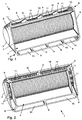
- a passenger-airbag module for a motor vehicle comprises a housing 1 with a diffuser chamber 2 for receiving a tubular gas generator 3 and an airbag chamber 4, in an airbag 5 is added folded up.
- the gas bag chamber 4 is funnel-shaped and peripherally bounded by housing walls 6. Between the diffuser chamber 2 and the airbag chamber 4, an intermediate wall 7 is arranged.
- the longitudinal housing walls 6 are designed to form flow channels 8 double-walled.
- Each of the flow channels 8 is divided by separating webs 9 in individual flow channels 10, wherein the individual flow channels 10 are each associated with a plurality of cylindrical passage openings 11 in the intermediate wall 7.
- the flow channels 8 and the housing walls 6 open in a funnel shape, starting from the intermediate wall 7, so that the compressed gas flowing from the diffuser chamber 2 through the flow channels 8 into the gas bag 5 is directed in a corresponding direction.
- the outward angular position of the flow channels 8 causes a preferred lateral deployment of the airbag 5, whereby an occupant is not shot directly from the expanding airbag 5.
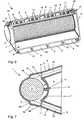
- the frontal housing walls 6 also have flow channels 8.
- the flow channels 8 at the end faces of the gas bag chamber 4 are likewise formed in the free space formed by the double-walled housing walls 6 and are in fluid communication with the diffuser chamber 2 via cylindrical passage openings 11.
- the end-side flow channels 8 are directed due to the funnel-shaped orientation of the housing walls 6 both with respect to a horizontal and a vertical center plane of the housing 1 in its installed position to the outside. Due to the orientation of the flow channels 8, the airbag 5 is primarily unfolded when the pressurized gas in the lateral direction, that is not directly to the occupant.
- the airbag 5 is folded in the airbag chamber 4, wherein the individual folds 12 are aligned substantially parallel to the longitudinal-side housing walls 6.
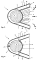
- the injection chamber 2 and the gas generator 3 have a substantially cylindrical cross-section, wherein the diameter of the tangentially adjacent to the intermediate wall 7 gas generator 3 is dimensioned such that a sickle-shaped Free space 14 is formed in the diffuser chamber 2.
- the intermediate wall 7 has a curvature 15 whose radius corresponds to the radius of the gas generator 3.
- webs 16 are formed with the passage openings 11 for connection to the U-shaped diffuser chamber 2.
- the essentially U-shaped free space 14 in the diffuser chamber 2 is interrupted by a holding web 17 at the vertex of the diffuser chamber 2, wherein the holding web 17 rests with its free end against the gas generator 3 and holds it against the intermediate wall 7.
- the diffuser chamber 2 and the gas generator 3 are essentially cylindrical in cross-section, wherein the holding web 17 is arranged in the middle of the intermediate wall 7, so that the gas generator 3 rests against the wall of the diffuser chamber 2 opposite the holding web 17 and enters Crescent-shaped free space 14 is formed in the diffuser chamber 2 in cross-section.
- the longitudinal flow channels 8 are tangent to the diffuser chamber 2.
- the diffuser chamber 2 is partially provided with a radius corresponding to the radius of the gas generator 3, in which the gas generator 3 is held by the integrally formed on the vault 15 intermediate wall 7 holding web 17.
- the radius of the diffuser chamber 2 opens to expand the diffuser chamber 2 in opposite flanges 18, which in the longitudinal sides of the housing walls 6 extending sections 19, wherein the adjoining the curvature 15 of the intermediate wall 7 webs 16 have the openings 11 and are formed in the connection region of the sections 19 with the longitudinal housing walls 6 of the same.
Description
Die Erfindung bezieht sich auf ein Beifahrer-Airbag-Modul für ein Kraftfahrzeug mit einem Gehäuse für einen aufblasbaren Gassack und einem Gasgenerator zur Erzeugung von Druckgas nach dem Oberbegriff des Patentanspruches 1.The invention relates to a passenger-airbag module for a motor vehicle with a housing for an inflatable airbag and a gas generator for generating compressed gas according to the preamble of
Die DE 197 07 997 A1 offenbart ein Airbag-Modul mit einer mit einem Diffusor verbundenen Gasgeneratorkammer und einer Gassackkammer. Zum gerichteten Einleiten des von dem Gasgenerator erzeugten Druckgases in den Gassack sind Gasführungen vorgesehen, die zueinander beabstandet und im Wesentlichen V-förmig zueinander angeordnet sind.DE 197 07 997 A1 discloses an airbag module with a gas generator chamber connected to a diffuser and an airbag chamber. For directed introduction of the compressed gas generated by the gas generator in the gas bag gas guides are provided, which are spaced from each other and arranged substantially V-shaped to each other.
Im Weiteren ist aus der gattungsbildenden DE 199 57 578 A1 eine aufblasbare Schutzvorrichtung für einen Insassen eines Kraftfahrzeuges bekannt, die zumindest einen in einem Gehäuse angeordneten und im Falle eines Unfalls aktivierbaren Gasgenerator sowie zumindest einen in Ruhelage gefalteten Luftsack umfasst. Zum gerichteten Einleiten der durch den Gasgenerator erzeugten Gase in den Luftsack ist zumindest eine rohrförmige Gasführung vorgesehen.Furthermore, from the generic DE 199 57 578 A1 an inflatable protective device for an occupant of a motor vehicle is known, which comprises at least one arranged in a housing and activated in the event of an accident gas generator and at least one folded in rest position airbag. For directed introduction of the gases generated by the gas generator in the airbag at least one tubular gas guide is provided.
Darüber hinaus offenbart die DE 196 18 817 A1 ein Beifahrer-Airbag-Modul für ein Kraftfahrzeug, das unterhalb einer Instrumententafel auf einem Strukturquerträger befestigt ist. Zwischen einem Gehäuse des Beifahrer-Airbag-Moduls und der Instrumententafel sind verformungsenergieaufnehmende Elemente vorgesehen, die den Schusskanal bilden.In addition, DE 196 18 817 A1 discloses a passenger-airbag module for a motor vehicle, which is mounted below an instrument panel on a structural cross member. Between a housing of the passenger airbag module and the instrument panel deformation energy absorbing elements are provided which form the firing channel.
Die zuvor erläuterten Airbagsysteme weisen den gemeinsamen Nachteil auf, dass bei einer Auslösung des Airbagmoduls die seitliche, also radiale Entfaltung des Gassackes gestört ist. Dadurch wird die Entfaltung des Gassackes relativ inhomogen und in Richtung des Insassen gelenkt, weshalb die Airbagsysteme verhältnismäßig aggressiv gegenüber dem Insassen sind.The previously explained airbag systems have the common disadvantage that when the airbag module is triggered, the lateral, ie radial, deployment of the airbag is disturbed. Thereby the deployment of the airbag is relatively inhomogeneous and directed towards the occupant, which is why the airbag systems are relatively aggressive to the occupant.
Es ist Aufgabe der Erfindung, ein Beifahrer-Airbag-Modul der eingangs genannten Art zu schaffen, mit dem eine hohe Sicherheit für einen Insassen, auch in einer Out Off Position (OOP) sichergestellt ist.It is an object of the invention to provide a passenger airbag module of the type mentioned, with a high security for an occupant, even in an out of position (OOP) is ensured.
Erfindungsgemäß wird die Aufgabe durch die Merkmale des Patentanspruches 1 gelöst.According to the invention the object is achieved by the features of
Der Verlauf der Strömungskanäle zum gerichteten Einleiten des Druckgases in den Gassack entspricht dem der längsseitigen Gehäusewände, die in einer Einbausituation des Beifahrer-Airbag-Moduls gegenüber einer horizontalen Mittelebene in einem bestimmten Winkel nach oben und unten gerichtet sind und sich somit trichterförmig öffnen. Diese Winkelstellung unterstützt die seitlich gerichtete Entfaltung des Gassackes beim Einströmen von Druckgas und verhindert das direkte Anschießen eines Insassen bei der Expansion. In Abhängigkeit von der Winkelstellung der Strömungskanäle sowie der Gehäusewände wird die Entfaltung des Gassackes aggressiver oder milder.The course of the flow channels for directed introduction of the compressed gas into the gas bag corresponds to the longitudinal housing walls, which are directed in a mounting situation of the passenger airbag module with respect to a horizontal center plane at a certain angle up and down and thus open in a funnel shape. This angular position supports the laterally directed deployment of the gas bag during the inflow of compressed gas and prevents the direct firing of an occupant during expansion. Depending on the angular position of the flow channels and the housing walls, the deployment of the airbag becomes more aggressive or milder.
Bei einer Ausgestaltung der Erfindung ist mindestens an einer der stirnseitigen Gehäusewände der Gassackkammer zumindest ein Strömungskanal für das Druckgas ausgebildet. Die durchgehende trichterförmige Öffnung der Gehäusewände und die dazu korrespondierende Ausrichtung der Strömungskanäle hat eine homogene Entfaltung des Gassackes sowie einen hohen Insassenschutz zur Folge, da der Gassack in axialer Richtung, also in Richtung des Insassen mit einer relativ geringen und in radialer Richtung, also seitwärts mit einer relativ hohen Expansionsgeschwindigkeit aufgeblasen wird.In one embodiment of the invention, at least one flow channel for the compressed gas is formed at least on one of the front-side housing walls of the airbag chamber. The continuous funnel-shaped opening of the housing walls and the corresponding alignment of the flow channels has a homogeneous deployment of the airbag and a high occupant protection result, since the airbag in the axial direction, ie in the direction of the occupant with a relatively small and in the radial direction, ie sideways with a relatively high expansion rate is inflated.
Erfindungsgemäß sind die entsprechenden Gehäusewände der Gassackkammer zur Bildung der Strömungskanäle doppelwandig gestaltet, wobei vorzugsweise ein Einblasmund des Gassackes die freien Enden der Gehäusewände abgedichtet einlagig übergreift und der Gassack in parallel zu den längsseitigen Gehäusewänden verlaufenden Falten gepackt ist. Somit sind zur Ausbildung der Strömungskanäle keine zusätzlichen Bauteile erforderlich und der seitlich ausgerichtete Eintritt des Druckgases in den Gassack ist mit einfachen Mitteln sichergestellt. Die Faltung des Gassackes in der Gassackkammer unterstützt die seitliche Entfaltung des Gassackes.According to the invention, the corresponding housing walls of the airbag chamber to form the flow channels are double-walled designed, wherein preferably a Einblasmund of the airbag, the free ends of the housing walls sealingly engages over a single layer and the gas bag is packed in parallel to the longitudinal housing walls extending wrinkles. Thus, no additional components are required to form the flow channels and the laterally oriented entry of the compressed gas into the gas bag is ensured by simple means. The folding of the airbag in the airbag chamber supports the lateral deployment of the airbag.
Weiterhin sind gemäß der Erfindung die doppelwandigen Gehäusewände durch Trennstege in mehrere Einzel-StrömungsKanäle unterteilt. Die Trennstege stabilisieren die doppelwandigen Gehäusewände und stellen die Strömungsrichtung des Druckgases sicher.Furthermore, according to the invention, the double-walled housing walls are divided by partitions into a plurality of individual flow channels. The dividers stabilize the double-walled housing walls and ensure the flow direction of the compressed gas.
Vorzugsweise ist jedem der Einzel-Strömungskanäle mindestens eine Durchtrittsöffnung für das Druckgas aus der Diffusorkammer zugeordnet. Die Durchtrittsöffnungen gewährleisten das Einströmen des Druckgases in den Gassack in einer ausreichenden Menge und Geschwindigkeit.Preferably, each of the individual flow channels is assigned at least one passage opening for the compressed gas from the diffuser chamber. The passage openings ensure the inflow of the compressed gas into the gas bag in a sufficient amount and speed.
Um Druckdifferenzen in der Diffusorkammer auszugleichen und gleichmäßige Druckverhältnisse im expandierenden Gassack zu erzeugen, weisen bevorzugt die Strömungskanäle und/oder die Einzel-Strömungskanäle und/oder die Durchtrittsöffnungen gleiche oder unterschiedliche Querschnitte auf. Somit kann die Gassackkinematik, die Entfaltungsgeschwindigkeit sowie die Entfaltungsrichtung des Gassackes gezielt beeinflusst und zur Systemabstimmung herangezogen werden.In order to compensate for pressure differences in the diffuser chamber and to produce uniform pressure conditions in the expanding gas bag, the flow channels and / or the individual flow channels and / or the through openings preferably have the same or different cross sections. Thus, the gas bag kinematics, the deployment speed and the deployment direction of the airbag can be selectively influenced and used for system tuning.
Zur Durchmischung und zur Abkühlung des aus dem Gasgenerator austretenden Druckgases, ist zumindest unterhalb der Durchtrittsöffnungen ein Freiraum in der Diffusorkammer ausgebildet.For mixing and for cooling the pressure gas emerging from the gas generator, a free space is formed in the diffuser chamber at least below the passage openings.
Es versteht sich, dass die vorstehend genannten und nachstehend noch zu erläuternden Merkmale nicht nur in der jeweils angegebenen Kombination, sondern auch in anderen Kombinationen verwendbar sind, ohne den Rahmen der vorliegenden Erfindung zu verlassen.It is understood that the features mentioned above and those yet to be explained not only in the each combination specified, but also in other combinations can be used without departing from the scope of the present invention.
Die Erfindung wird im Folgenden anhand mehrerer Ausführungsbeispiele unter Bezugnahme auf die zugehörigen Zeichnungen näher erläutert. Es zeigen:
- Fig. 1
- eine perspektivische Darstellung eines erfindungsgemäßen Beifahrer-Airbag-Moduls,
- Fig. 2
- eine perspektivische Darstellung des Beifahrer-Airbag-Moduls in einer ersten alternativen Ausgestaltung,
- Fig. 3
- einen Längsschnitt durch die Darstellung nach Fig. 2,
- Fig. 4
- einen Längsschnitt durch die Darstellung nach Fig. 2 in einer ersten alternativen Ausgestaltung,
- Fig. 5
- einen Längsschnitt durch die Darstellung nach Fig. 2 in einer zweiten alternativen Ausgestaltung,
- Fig. 6
- eine perspektivische Darstellung des Beifahrer-Airbag-Moduls in einer zweiten alternativen Ausgestaltung,
- Fig. 7
- einen Längsschnitt durch die Darstellung nach Fig. 6.
- Fig. 1
- a perspective view of a passenger airbag module according to the invention,
- Fig. 2
- a perspective view of the passenger airbag module in a first alternative embodiment,
- Fig. 3
- a longitudinal section through the illustration of FIG. 2,
- Fig. 4
- 3 a longitudinal section through the illustration according to FIG. 2 in a first alternative embodiment,
- Fig. 5
- 3 a longitudinal section through the illustration according to FIG. 2 in a second alternative embodiment,
- Fig. 6
- a perspective view of the passenger airbag module in a second alternative embodiment,
- Fig. 7
- a longitudinal section through the illustration of FIG. 6th
Ein Beifahrer-Airbag-Modul für ein Kraftfahrzeug umfasst ein Gehäuse 1 mit einer Diffusorkammer 2 zur Aufnahme eines rohrförmigen Gasgenerators 3 sowie eine Gassackkammer 4, in der ein Gassack 5 zusammengefaltet aufgenommen ist. Die Gassackkammer 4 ist trichterförmig ausgebildet und umfangsseitig durch Gehäusewände 6 begrenzt. Zwischen der Diffusorkammer 2 und der Gassackkammer 4 ist eine Zwischenwand 7 angeordnet.A passenger-airbag module for a motor vehicle comprises a
Nach Fig. 1 sind die längsseitigen Gehäusewände 6 zur Ausbildung von Strömungskanälen 8 doppelwandig ausgeführt. Jeder der Strömungskanäle 8 ist durch Trennstege 9 in Einzel-Strömungskanäle 10 unterteilt, wobei den Einzel-Strömungskanälen 10 jeweils mehrere zylindrische Durchtrittsöffnungen 11 in der Zwischenwand 7 zugeordnet sind. Die Strömungskanäle 8 sowie die Gehäusewände 6 öffnen sich ausgehend von der Zwischenwand 7 trichterförmig, so dass das aus der Diffusorkammer 2 durch die Strömungskanäle 8 in den Gassack 5 einströmende Druckgas in eine dementsprechende Richtung geleitet wird. Die nach außen gerichtete Winkelstellung der Strömungskanäle 8 bewirkt eine bevorzugte seitliche Entfaltung des Gassackes 5, wodurch ein Insasse nicht direkt von dem expandierenden Gassack 5 angeschossen wird.According to Fig. 1, the
Um die Aggressivität des Beifahrer-Airbag-Moduls bei der Expansion des Gassacks darüber hinaus abzumildern, weisen gemäß Fig. 2 neben den längsseitigen Gehäusewänden 6 auch die stirnseitigen Gehäusewände 6 Strömungskanäle 8 auf. Die Strömungskanäle 8 an den Stirnseiten der Gassackkammer 4 sind ebenfalls in dem von den doppelwandigen Gehäusewänden 6 gebildeten Freiraum ausgebildet und stehen über zylindrische Durchtrittsöffnungen 11 mit der Diffusorkammer 2 in Strömungsverbindung. Die stirnseitigen Strömungskanäle 8 sind aufgrund der trichterförmigen Ausrichtung der Gehäusewände 6 sowohl gegenüber einer horizontalen als auch einer vertikalen Mittelebene des Gehäuses 1 in ihrer Einbaulage nach außen gerichtet. Aufgrund der Ausrichtung der Strömungskanäle 8 wird der Gassack 5 bei einströmendem Druckgas primär in seitlicher Richtung, also nicht direkt zum Insassen hin entfaltet.In order to further mitigate the aggressiveness of the front passenger airbag module in the expansion of the gas bag, according to FIG. 2, in addition to the
In Fig. 3 ist der Gassack 5 in der Gassackkammer 4 gefaltet, wobei die einzelnen Falten 12 im Wesentlichen parallel zu den längsseitigen Gehäusewänden 6 ausgerichtet sind. Ein Einblasmund 13 des Gassackes 5 übergreift abgedichtet einlagig die freien Enden der Gehäusewände 6. Die Diffusorkammer 2 und der Gasgenerator 3 weisen einen im Wesentlichen zylindrischen Querschnitt auf, wobei der Durchmesser des an der Zwischenwand 7 tangential anliegenden Gasgenerators 3 derart bemessen ist, dass ein sichelförmiger Freiraum 14 in der Diffusorkammer 2 ausgebildet ist.In Fig. 3, the
Bei dem Gehäuse 1 nach Fig. 4 weist die Zwischenwand 7 eine Wölbung 15 auf, deren Radius dem Radius des Gasgenerators 3 entspricht. Beidseitig zur Wölbung 15 der Zwischenwand 7 sind Stege 16 mit den Durchtrittsöffnungen 11 zur Verbindung mit der U-förmigen Diffusorkammer 2 ausgebildet. Der im Querschnitt im Wesentlichen U-förmige Freiraum 14 in der Diffusorkammer 2 ist durch einen Haltesteg 17 im Scheitelpunkt der Diffusorkammer 2 unterbrochen, wobei der Haltesteg 17 mit seinem freien Ende an dem Gasgenerator 3 anliegt und diesen gegen die Zwischenwand 7 hält.In the
Gemäß Fig. 5 sind die Diffusorkammer 2 und der Gasgenerator 3 im Querschnitt im Wesentlichen zylindrisch ausgebildet, wobei der Haltesteg 17 in der Mitte der Zwischenwand 7 angeordnet ist, so dass der Gasgenerator 3 an der dem Haltesteg 17 gegenüberliegenden Wandung der Diffusorkammer 2 anliegt und ein im Querschnitt sichelförmiger Freiraum 14 in der Diffusorkammer 2 ausgebildet ist. Die längsseitigen Strömungskanäle 8 gehen tangential von der Diffusorkammer 2 ab.According to FIG. 5, the
Nach Fig. 7 ist die Diffusorkammer 2 bereichsweise mit einem zu dem Radius des Gasgenerators 3 korrespondierenden Radius versehen, in dem der Gasgenerator 3 durch den an der die Wölbung 15 aufweisenden Zwischenwand 7 angeformten Haltesteg 17 gehalten wird. Der Radius der Diffusorkammer 2 mündet zur Erweiterung der Diffusorkammer 2 in gegenüberliegende Flansche 18, die in die längsseitigen Gehäusewände 6 verlängernde Abschnitte 19 übergehen, wobei die sich an die Wölbung 15 der Zwischenwand 7 anschließenden Stege 16 die Durchtrittsöffnungen 11 aufweisen und im Anbindungsbereich der Abschnitte 19 mit den längsseitigen Gehäusewänden 6 an denselben angeformt sind.According to Fig. 7, the
- 1.1.
- Gehäusecasing
- 2.Second
- Diffusorkammerdiffuser chamber
- 3.Third
- Gasgeneratorinflator
- 4.4th
- GassackkammerAirbag chamber
- 5.5th
- Gassackairbag
- 6.6th
- Gehäusewandhousing wall
- 7.7th
- Zwischenwandpartition
- 8.8th.
- Strömungskanalflow channel
- 9.9th
- Trennstegdivider
- 10.10th
- Einzel-StrömungskanalSingle-flow channel
- 11.11th
- DurchtrittsöffnungThrough opening
- 12.12th
- Faltewrinkle
- 13.13th
- Einblasmundinflation opening
- 14.14th
- Freiraumfree space
- 15.15th
- Wölbungbulge
- 16.16th
- Stegweb
- 17.17th
- Haltestegholding web
- 18.18th
- Flanschflange
- 19.19th
- Abschnittsection
- AA
- Pfeilarrow
- BB
- Pfeilarrow
Claims (8)
- Passenger airbag module for a motor vehicle having a housing (1) for an inflatable airbag (5) and having a gas generator (3) for generating pressure gas, wherein the housing (1) has a diffuser chamber (2) for the gas generator (3) and an airbag chamber (4) widening in a funnel-shaped manner and for the preferred deployment of the airbag (5) in lateral direction (arrow A) at least one flow channel (8) for the pressure gas that is connected to the diffuser chamber (2) is formed at least at one of the longitudinal-side housing walls (6) of the airbag chamber (4), characterized in that the housing walls (6) of the airbag chamber (4) are of a double-walled design to form the flow channels (8) and are subdivided by dividing webs (9) into a plurality of individual flow channels (10).
- Passenger airbag module according to claim 1, characterized in that at least one flow channel (8) for the pressure gas is formed at least at one of the front housing walls (6) of the airbag chamber (4).
- Passenger airbag module according to claim 1 or 2, characterized in that an air inlet mouth (13) of the airbag (5) with a single layer overlaps the free ends of the housing walls (6) in a sealed manner and the airbag (5) is packed in folds (12) extending parallel to the longitudinal-side housing walls (6).
- Passenger airbag module according to one of claims 1 to 3, characterized in that at least one through-opening (11) for the pressure gas from the diffuser chamber (2) is associated with each of the individual flow channels (10).
- Passenger airbag module according to one of claims 1 to 4, characterized in that the flow channels (8) and/or the individual flow channels (10) and/or the through-openings (11) have the same or different cross sections.
- Passenger airbag module according to one of claims 1 to 5, characterized in that a free space in the diffuser chamber (2) is formed at least below the through-openings (11).
- Passenger airbag module according to one of claims 1 to 6, characterized in that the airbag chamber (4) is formed by the housing walls (6) and/or the flow channels (8) and the partition wall (7).
- Passenger airbag module according to one of claims 1 to 7, characterized in that the airbag (5) overlaps the free ends of the flow channels (8) only with a single layer.
Applications Claiming Priority (2)
| Application Number | Priority Date | Filing Date | Title |
|---|---|---|---|
| DE10142596 | 2001-08-31 | ||
| DE2001142596 DE10142596A1 (en) | 2001-08-31 | 2001-08-31 | Passenger airbag module for a motor vehicle |
Publications (3)
| Publication Number | Publication Date |
|---|---|
| EP1288083A2 EP1288083A2 (en) | 2003-03-05 |
| EP1288083A3 EP1288083A3 (en) | 2003-05-07 |
| EP1288083B1 true EP1288083B1 (en) | 2006-01-04 |
Family
ID=7697185
Family Applications (1)
| Application Number | Title | Priority Date | Filing Date |
|---|---|---|---|
| EP20020018417 Expired - Fee Related EP1288083B1 (en) | 2001-08-31 | 2002-08-16 | Passenger airbag module for a vehicle |
Country Status (3)
| Country | Link |
|---|---|
| EP (1) | EP1288083B1 (en) |
| DE (2) | DE10142596A1 (en) |
| ES (1) | ES2254570T3 (en) |
Families Citing this family (9)
| Publication number | Priority date | Publication date | Assignee | Title |
|---|---|---|---|---|
| DE10214730B4 (en) * | 2002-04-03 | 2010-07-29 | Delphi Technologies, Inc., Troy | safety device |
| DE10337703B4 (en) * | 2003-08-16 | 2010-01-14 | GM Global Technology Operations, Inc., Detroit | Airbag module for motor vehicles |
| DE102004023680A1 (en) * | 2004-05-13 | 2005-12-01 | Adam Opel Ag | Attachment device for airbag module has separate attachment frame connected to cladding part and/or to cladding part support and with attachment elements that attach airbag module to attachment frame |
| DE202004012303U1 (en) * | 2004-08-05 | 2004-12-09 | Trw Automotive Safety Systems Gmbh | Airbag module for a vehicle occupant restraint |
| DE102004054528B4 (en) * | 2004-11-05 | 2007-04-26 | Takata-Petri Ag | Housing for airbag module |
| DE102005010324B4 (en) * | 2005-03-03 | 2007-05-03 | Autoliv Development Ab | Airbag housing |
| DE102005049156A1 (en) * | 2005-10-14 | 2007-04-19 | GM Global Technology Operations, Inc., Detroit | Method for fastening a gas generator in a gas generator chamber and housing with a gas generator chamber |
| DE102016215514A1 (en) | 2016-08-18 | 2018-02-22 | Volkswagen Aktiengesellschaft | Airbag module assembly |
| DE102017002663A1 (en) | 2017-03-20 | 2018-09-20 | Audi Ag | airbag module |
Family Cites Families (6)
| Publication number | Priority date | Publication date | Assignee | Title |
|---|---|---|---|---|
| US3514124A (en) * | 1967-08-16 | 1970-05-26 | Eaton Yale & Towne | Vehicle safety device |
| US5180188A (en) * | 1991-08-29 | 1993-01-19 | General Motors Corporation | Inflation gas flow directing member for air bag system |
| DE19618817B4 (en) * | 1996-05-10 | 2007-09-13 | Adam Opel Ag | Passenger airbag module in a motor vehicle |
| US5873598A (en) * | 1996-08-27 | 1999-02-23 | Toyo Tire & Rubber Co., Ltd. | Air bag device |
| DE19957578B4 (en) * | 1999-11-30 | 2012-11-15 | GM Global Technology Operations LLC (n. d. Ges. d. Staates Delaware) | Inflatable protection device for an occupant of a motor vehicle |
| DE20014064U1 (en) * | 2000-08-16 | 2001-05-23 | Trw Repa Gmbh | Airbag module |
-
2001
- 2001-08-31 DE DE2001142596 patent/DE10142596A1/en not_active Withdrawn
-
2002
- 2002-08-16 EP EP20020018417 patent/EP1288083B1/en not_active Expired - Fee Related
- 2002-08-16 DE DE50205502T patent/DE50205502D1/en not_active Expired - Lifetime
- 2002-08-16 ES ES02018417T patent/ES2254570T3/en not_active Expired - Lifetime
Also Published As
| Publication number | Publication date |
|---|---|
| EP1288083A3 (en) | 2003-05-07 |
| DE10142596A1 (en) | 2003-03-20 |
| ES2254570T3 (en) | 2006-06-16 |
| DE50205502D1 (en) | 2006-03-30 |
| EP1288083A2 (en) | 2003-03-05 |
Similar Documents
| Publication | Publication Date | Title |
|---|---|---|
| EP2203330B1 (en) | Airbag module | |
| DE4442202A1 (en) | Passenger airbag module | |
| EP1288083B1 (en) | Passenger airbag module for a vehicle | |
| EP1928708A1 (en) | Airbag device for motor vehicles | |
| EP1399336B1 (en) | Housing for an airbag module | |
| EP1593557A1 (en) | Module with housing and generator for a sideairbag | |
| DE20207388U1 (en) | An air bag assembly | |
| DE4121039A1 (en) | Gas generator esp. for airbag in vehicle crash safety system - includes filter chamber, combustion chamber with detonator and propellant for gas generation, etc. | |
| DE10235128A1 (en) | Joint airbag system for two passengers has two separate gas bags sealed from each other by deflectors and folded into common housing set in dashboard and connected to common gas generator | |
| WO2007045438A1 (en) | Lateral impact protection device | |
| DE102004038459B4 (en) | Airbag module for the protection of a motor vehicle occupant | |
| EP2195204B1 (en) | Inflation device for an airbag module | |
| DE10061946A1 (en) | Gas generator and inflatable bag, for inflation of passenger protection airbag, is equipped with specifically shaped gas guiding plate, joined to textile guide layer | |
| DE19933521A1 (en) | Vehicle airbag | |
| EP1182099B1 (en) | Vehicle passengers protection system with side air-bag | |
| DE19909426B4 (en) | airbag unit | |
| EP1607281B1 (en) | Passenger-side airbag module | |
| EP1088711B1 (en) | Passenger side air bag module for a motor vehicle | |
| DE10154964B4 (en) | airbag module | |
| EP1273485B1 (en) | Airbag module with an inflatable member with variable volume | |
| EP1211145A1 (en) | Steering wheel airbag for a vehicle | |
| DE10109057B4 (en) | Housing for an airbag module of a motor vehicle | |
| DE102011016381B4 (en) | Gas generator with a tubular housing and vehicle occupant restraint system | |
| DE202005008938U1 (en) | Hybrid gas generator for vehicle occupant restraining system has discharge opening in compressed gas chamber closed by outlet diaphragm and arranged in direction of propagation of shock wave, which destroys discharge diaphragm, and filter | |
| DE19904320B4 (en) | Occupant protection device for a motor vehicle with an airbag |
Legal Events
| Date | Code | Title | Description |
|---|---|---|---|
| PUAI | Public reference made under article 153(3) epc to a published international application that has entered the european phase |
Free format text: ORIGINAL CODE: 0009012 |
|
| AK | Designated contracting states |
Kind code of ref document: A2 Designated state(s): AT BE BG CH CY CZ DE DK EE ES FI FR GB GR IE IT LI LU MC NL PT SE SK TR |
|
| AX | Request for extension of the european patent |
Extension state: AL LT LV MK RO SI |
|
| PUAL | Search report despatched |
Free format text: ORIGINAL CODE: 0009013 |
|
| AK | Designated contracting states |
Designated state(s): AT BE BG CH CY CZ DE DK EE ES FI FR GB GR IE IT LI LU MC NL PT SE SK TR |
|
| AX | Request for extension of the european patent |
Extension state: AL LT LV MK RO SI |
|
| 17P | Request for examination filed |
Effective date: 20031103 |
|
| AKX | Designation fees paid |
Designated state(s): DE ES FR GB IT PT |
|
| 17Q | First examination report despatched |
Effective date: 20040921 |
|
| GRAP | Despatch of communication of intention to grant a patent |
Free format text: ORIGINAL CODE: EPIDOSNIGR1 |
|
| GRAS | Grant fee paid |
Free format text: ORIGINAL CODE: EPIDOSNIGR3 |
|
| GRAA | (expected) grant |
Free format text: ORIGINAL CODE: 0009210 |
|
| RBV | Designated contracting states (corrected) |
Designated state(s): DE ES FR GB |
|
| AK | Designated contracting states |
Kind code of ref document: B1 Designated state(s): DE ES FR GB |
|
| REG | Reference to a national code |
Ref country code: GB Ref legal event code: FG4D Free format text: NOT ENGLISH |
|
| GBT | Gb: translation of ep patent filed (gb section 77(6)(a)/1977) |
Effective date: 20060123 |
|
| REF | Corresponds to: |
Ref document number: 50205502 Country of ref document: DE Date of ref document: 20060330 Kind code of ref document: P |
|
| REG | Reference to a national code |
Ref country code: ES Ref legal event code: FG2A Ref document number: 2254570 Country of ref document: ES Kind code of ref document: T3 |
|
| ET | Fr: translation filed | ||
| PLBE | No opposition filed within time limit |
Free format text: ORIGINAL CODE: 0009261 |
|
| STAA | Information on the status of an ep patent application or granted ep patent |
Free format text: STATUS: NO OPPOSITION FILED WITHIN TIME LIMIT |
|
| 26N | No opposition filed |
Effective date: 20061005 |
|
| REG | Reference to a national code |
Ref country code: GB Ref legal event code: 732E Free format text: REGISTERED BETWEEN 20090219 AND 20090225 |
|
| REG | Reference to a national code |
Ref country code: GB Ref legal event code: 732E Free format text: REGISTERED BETWEEN 20090305 AND 20090311 |
|
| REG | Reference to a national code |
Ref country code: GB Ref legal event code: 732E Free format text: REGISTERED BETWEEN 20091029 AND 20091104 |
|
| REG | Reference to a national code |
Ref country code: GB Ref legal event code: 732E Free format text: REGISTERED BETWEEN 20091105 AND 20091111 |
|
| REG | Reference to a national code |
Ref country code: DE Ref legal event code: R081 Ref document number: 50205502 Country of ref document: DE Owner name: GM GLOBAL TECHNOLOGY OPERATIONS LLC (N. D. GES, US Free format text: FORMER OWNER: GM GLOBAL TECHNOLOGY OPERATIONS, INC., DETROIT, US Effective date: 20110323 Ref country code: DE Ref legal event code: R081 Ref document number: 50205502 Country of ref document: DE Owner name: GM GLOBAL TECHNOLOGY OPERATIONS LLC (N. D. GES, US Free format text: FORMER OWNER: GM GLOBAL TECHNOLOGY OPERATIONS, INC., DETROIT, MICH., US Effective date: 20110323 |
|
| PGFP | Annual fee paid to national office [announced via postgrant information from national office to epo] |
Ref country code: GB Payment date: 20120815 Year of fee payment: 11 |
|
| PGFP | Annual fee paid to national office [announced via postgrant information from national office to epo] |
Ref country code: DE Payment date: 20120808 Year of fee payment: 11 Ref country code: FR Payment date: 20120823 Year of fee payment: 11 Ref country code: ES Payment date: 20120907 Year of fee payment: 11 |
|
| GBPC | Gb: european patent ceased through non-payment of renewal fee |
Effective date: 20130816 |
|
| PG25 | Lapsed in a contracting state [announced via postgrant information from national office to epo] |
Ref country code: DE Free format text: LAPSE BECAUSE OF NON-PAYMENT OF DUE FEES Effective date: 20140301 |
|
| REG | Reference to a national code |
Ref country code: FR Ref legal event code: ST Effective date: 20140430 |
|
| REG | Reference to a national code |
Ref country code: DE Ref legal event code: R119 Ref document number: 50205502 Country of ref document: DE Effective date: 20140301 |
|
| PG25 | Lapsed in a contracting state [announced via postgrant information from national office to epo] |
Ref country code: GB Free format text: LAPSE BECAUSE OF NON-PAYMENT OF DUE FEES Effective date: 20130816 |
|
| PG25 | Lapsed in a contracting state [announced via postgrant information from national office to epo] |
Ref country code: FR Free format text: LAPSE BECAUSE OF NON-PAYMENT OF DUE FEES Effective date: 20130902 |
|
| REG | Reference to a national code |
Ref country code: ES Ref legal event code: FD2A Effective date: 20140905 |
|
| PG25 | Lapsed in a contracting state [announced via postgrant information from national office to epo] |
Ref country code: ES Free format text: LAPSE BECAUSE OF NON-PAYMENT OF DUE FEES Effective date: 20130817 |