BACKGROUND OF THE INVENTION
Field of the Invention
-
The invention relates to an image forming
apparatus, which can optimize the rising sequence of
a fan and shorten the time from the start of a copy
job to the delivery of the first sheet out of the
apparatus.
Description of Related Art
-
An example of the image forming apparatus
according to the prior art will hereinafter be
described with reference to Figs. 6 and 7 of the
accompanying drawings.
-
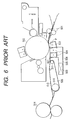
Fig. 6 is a typical cross-sectional view of a
photosensitive member, a transferring device, a
stripping device, a transport device and a fixing
device in an image forming portion contained in the
image forming apparatus (not shown).
-
Fig. 7 simply shows the relation between the
time from the standby state through the copying
operation to the stop of the copying operation of the
image forming apparatus and the operation sequence of
a fan.
-
As shown in Fig. 6, a sheet P transported to
registration rollers 501 as sheet supplying means by
feeding and transporting means (not shown) comes into
between a photosensitive drum 502 which is a
photosensitive member bearing thereon a toner image
formed by electrophotography and being rotated and
transferring means 503 and stripping means 504
disposed in proximity to and opposed relationship
with the photosensitive drum 502.
-
In a transferring area, the sheet P begins to
contact with the photosensitive drum 502 which is an
image bearing member, passes through the transferring
area and arrives at the corona discharge area of the
stripping means 504, whereupon the sheet P which has
so far been in contact with the photosensitive drum
502 is stripped from the photosensitive drum 502.
-
The sheet P thus stripped is completely
stripped from the photosensitive drum 502 by suction
means 505 playing the auxiliary role of the stripping
means 504, and is sent to transporting means 506
along a guide 507 provided on the sheet passing
surface of the stripping means 504. The suction
means 505 is comprised of a duct 508 and a stripping
fan 509.
-
Further, the transporting means 506 is
comprised of a driving runner 510, a driven runner
511 and a transport belt 513 looped around and driven
by the driving runner 510 and the driven runner 511.
The transported sheet P is transported to fixing
means 514 by the transport belt 513.
-
Here, the stripping fan 509 assumes the
starting sequence as shown in Fig. 7. In a graph as
shown in Fig. 7, a section up to time T1 of a line
designated by "a" represents the standby state of the
image forming apparatus. In the standby state, a
user performs a series of operations in preparation
for the copying operation, and when he depresses a
copy start button at T1, the stripping fan 509 is
started. The stripping fan 509 rises to a use,
rotating speed at T1-T3. T2 and T2' indicate the
time when the leading edge of the sheet P arrives at
the registration rollers 501.
-
If the leading edge of the sheet P has already
arrived at the registration rollers 501 at T2 (T2<T3),
the sheet P stands by at the position of the
registration rollers 501 until T3 when the stripping
fan 509 rises. Or if the leading edge of the sheet P
has arrived at the registration rollers 501 at T2'
(T2'>T3) whereat the stripping fan 509 is already in
its rising state, the sheet P does not stand by at
the registration rollers 501 but shift is made to the
image forming operation.
-
Thereafter, the image forming operation is
started and at T4, the last sheet P is delivered out
of the image forming apparatus, whereupon the
stripping fan 509 performs the stopping operation.
-
Also, if as previously described, in the line
designated by "a" in the graph, the leading edge of
the sheet P arrives at the registration rollers 501
at T2, as a measure for shortening the time for which
the sheet P stands by at the position of the
registration rollers 501, use has been made of a
sequence as shown by a line designated by "b" in the
graph for pre-starting the stripping fan 509 in the
standby state.
-
In recent years, as seen in an image forming
apparatus such as a copying machine or a printer for
forming an image which is provided with a post-processing
apparatus having the functions of sorting,
stapling, punching and binding sheets on which images
have been formed, the complication of the apparatus
system has been advanced while on the other hand, the
higher speed of the apparatus has also been advanced
to improve productivity. Further, with the advance
of the higher speed of the apparatus on the one hand,
the trend for energy saving has become popular as the
consideration for environmental problems. So, the
above-described prior art has suffered from such
problems as will be shown below.
-
In the prior-art image forming apparatuses of
low and medium speeds, a method of corona-discharging
to a sheet has been popular as a method of stripping
a sheet from a photosensitive member. In recent
years, however, the higher speed of the image forming
apparatuses have been advanced to improve
productivity and it has become difficult to strip a
sheet from the photosensitive member by the
aforedescribed stripping method alone. For example,
as the image forming apparatus becomes higher in
speed, the rotating speed of the photosensitive
member increases and therefore, sufficient discharge
is not done to the sheet and bad stripping may result
and jam may sometimes be caused.
-
So, a solution to these problems has been
attempted by a countermeasure such as strengthening
the discharge current or sucking the sheet by a fan
through a duct in the stripping portion. Also, in
order that the sheet stripped from the photosensitive
member may be standby transported to the fixing means
even if the higher speed is advanced, use has often
been made of a fan in the transporting means to suck
the sheet by the fan through a duct to thereby suck
the sheet onto the transporting means as well as to
satisfy stable transportability.
-
However, when the higher speed is further
advanced, suction means greater in suction force
becomes necessary in order to improve the
aforementioned separability and transportability.
Consequently, the fan necessarily becomes bulky and
this has led to such a problem as will be described
below.
-
A bulky fan, as compared with the fan
heretofore used, becomes long in its rising time and
therefore, if for example, the fan is started from a
point of time at which the user has operated a copy
button to thereby start a copy job, a certain extent
of time is required until the rotation of the fan
becomes stable and thus, even a sheet started to be
transported stops at a predetermined position for the
time until the rotation of the fan becomes stable.
This leads to the problem that the time until the
first sheet after the start of the copy job is
delivered out of the apparatus becomes long, and this
is against the aforedescribed improvement in the
productivity of the image forming apparatus.
-
Therefore, in the prior art, the shortening of
the rising time has been contrived by operating the
fan at a half of the ordinary use rotating speed or
keeping the fan at the ordinary use rotating speed in
the standby state of the image forming apparatus.
However, depending on the installation environment
(temperature and humidity) of the image forming
apparatus or the type of paper great in rigidity such
as thick paper good in separability, there is a case
where the rotating speed of the fan is excessive. In
such case, the fan is operated even during a time
when the suction of a sheet is not required and thus,
consumes extra electric power, and this is against
the above-described trend for energy saving.
SUMMARY OF THE INVENTION
-
The present invention has been made in order to
solve the above-noted problems peculiar to the prior
art and the object thereof is to provide an image
forming apparatus in which the rising sequence of a
fan made bulkier with the higher speed of the image
forming apparatus is reconsidered and the time from
the start of a copy job until the first sheet is
delivered out of the apparatus is shortened to
thereby make high productivity possible and as the
consideration for environmental problems, the
consumption of extra electric power in the standby
state of the image forming apparatus is suppressed.
-
In order to achieve the above object, an image
forming apparatus according to the present invention
comprises:
- sheet supplying means for supplying a sheet to
a photosensitive member;
- transferring means for transferring an image
from the photosensitive member to the sheet;
- stripping means provided downstream of the
transferring means in the transport direction of the
sheet for stripping the sheet from the photosensitive
member;
- transporting means for transporting the
stripped sheet to fixing means;
- a duct having an opening portion on the
stripping means side thereof;
- one or more fans provided in the other opening
portion of the duct to suck a side opposite to a side
of the sheet on which the image is formed; and
- operation signal detecting means for detecting
electrical signals by a user's predetermined
operation in preparation for the start of a copy job,
and
- when the operation signal detecting means
detects at least one of the electrical signals by the
predetermined operation, at least one of the fans is
started in synchronism with the detection signal
thereof.
-
-
Also, an image forming apparatus according to
the present invention comprises:
- sheet supplying means for supplying a sheet to
a photosensitive member;
- transferring means for transferring an image
from the photosensitive member to the sheet;
- stripping means provided downstream of the
transferring means in the transport direction of the
sheet for stripping the sheet from the photosensitive
member;
- transporting means for transporting the
stripped sheet to fixing means;
- a duct having an opening portion on the
transporting means side thereof;
- one or more fans provided in the other opening
portion of the duct to suck a side opposite to a side
of the sheet on which the image is formed; and
- operation signal detecting means for detecting
electrical signals by a user's predetermined
operation in preparation for the start of a copy job,
and
- when the operation signal detecting means
detects at least one of the electrical signals by the
predetermined operation, at least one of the fans is
started in synchronism with the detection signal
thereof.
-
-
It is preferable that after the termination of
the operation of the image forming apparatus, at
least one of the fans be stopped after it is operated
for a predetermined time while maintaining a
predetermined rotating speed.
-
It is preferable that when the operation signal
detecting means detects at least one of the
electrical signals by the predetermined operation, at
least one of the fans be started in synchronism with
the detection signal thereof, and when the image
forming apparatus does not detect an image forming
signal for a predetermined time, the fans be stopped.
-
The image forming apparatus has environment
detecting means for detecting environment, and it is
preferable that when the operation signal detecting
means detects at least one of the electrical signals
by the predetermined operation and the environment
detecting means detects that the apparatus is in
predetermined environment, the fans maintain their
stopped state, and the fans be started in synchronism
with the signal of the user's copy job starting
operation.
-
The image forming apparatus has environment
detecting means for detecting environment, and it is
preferable that the rotating speed of the fans be
fluctuated in conformity with the environment
detected by the environment detecting means.
-
Also, an image forming apparatus according to
the present invention comprises:
- sheet supplying means for supplying a sheet to
a photosensitive member;
- transferring means for transferring an image
from the photosensitive member to the sheet;
- stripping means provided downstream of the
transferring means in the transport direction of the
sheet for stripping the sheet from the photosensitive
member;
- transporting means for transporting the
stripped sheet to fixing means;
- a duct having an opening portion on the
stripping means side thereof;
- one or more fans provided in the other opening
portion of the duct to suck a side opposite to a side
of the sheet on which the image is formed; and
- environment detecting means for detecting
environment, and
- when the environment detecting means detects
that the apparatus is in a predetermined environment,
the rotation of the fans is stopped or the rotating
speed of the fans is fluctuated.
-
-
Also, an image forming apparatus according to
the present invention comprises:
- sheet supplying means for supplying a sheet to
a photosensitive member;
- transferring means for transferring an image
from the photosensitive member to the sheet;
- stripping means provided downstream of the
transferring means in the transport direction of the
sheet for stripping the sheet from the photosensitive
member;
- transporting means for transporting the
stripped sheet to fixing means;
- a duct having an opening portion on the
stripping means side thereof;
- one or more fans provided in the other opening
portion of the duct to suck a side opposite to a side
of the sheet on which the image is formed; and
- type detecting means for detecting the type of
the sheet, and
- when the type detecting means detects that the
sheet is a predetermined type of paper, the rotation
of the fans is stopped or the rotating speed of the
fans is fluctuated in conformity with the type of
paper.
-
-
As described above, the fans rise while the
user is performing a predetermined operation in
preparation for a copy job and therefore, it becomes
possible to shorten the time from after the start of
the copy job until the first sheet is delivered out
of the image forming apparatus, and high productivity
can be secured.
-
Further, the fans are stopped in the standby
state of the image forming apparatus and therefore,
it becomes possible to suppress the consumption of
extra electric power, and by changing the rotating
speed of the fans to a necessary rotating speed in
conformity with the installation environment of the
image forming apparatus or the type of the sheet, it
becomes possible to suppress the consumption of extra
electric power, and the purpose of the consideration
for environmental problems can be achieved.
-
As described above, the present invention
starts the fans when the electrical signal by the
predetermined operation before the start of the copy
job, to thereby shorten the time from after the start
of the copy job until the first sheet is delivered
out of the apparatus, whereby high productivity is
made possible and it becomes possible to suppress the
consumption of extra electric power in the standby
state of the image forming apparatus.
BRIEF DESCRIPTION OF THE DRAWINGS
-
- Fig. 1 is a cross-sectional view typically
showing an image forming apparatus according to an
embodiment of the present invention.
- Fig. 2 is a cross-sectional view typically
showing the surroundings of the stripping device and
transferring device of the image forming apparatus
according to the embodiment of the present invention.
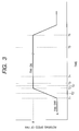
- Fig. 3 shows the operation sequence of a fan
according to the embodiment of the present invention.
- Fig. 4 shows the operation sequence of the fan
according to the embodiment of the present invention.
- Fig. 5 is a flowchart illustrating the
operation procedure of the fan of the image forming
apparatus according to the embodiment of the present
invention.
- Fig. 6 is a cross-sectional view typically
showing an image forming portion according to the
prior art.
- Fig. 7 shows the operation sequence of a fan in
an image forming apparatus according to the prior art.
-
DESCRIPTION OF THE PREFERRED EMBODIMENT
-
An image forming apparatus according to a
preferred embodiment of the present invention will
hereinafter be described in detail by way of example
with reference to Figs. 1 to 4. However, the
dimensions, materials, shapes, relative dispositions,
etc. of constituent parts described in the embodiment
are not intended to restrict the scope of the
invention thereto unless otherwise specified.
-
Fig. 1 is a typical cross-sectional view of the
image forming apparatus according to the embodiment
of the present invention, Fig. 2 is an enlarged
typical cross-sectional view showing the surroundings
of the stripping means and transferring means of the
image forming apparatus shown in Fig. 1, Fig. 3
simply shows the relation between the time of the
standby state through the copying operation till the
stop of the copying operation of the image forming
apparatus and the operation sequence of a stripping
fan, and Fig. 4 simply shows the relation between the
time of the standby state through the copying
operation till the stop of the copying operation when
the image forming apparatus is installed in
predetermined environment and the operation sequence
of the stripping fan.
-
In the present embodiment, the operation
sequence of the stripping fan provided in stripping
means through a duct will be described in detail, but
the operation sequence of a fan provided in
transporting means through a duct is substantially
similar thereto and therefore need not be described.
-
In Fig. 1, the reference numeral 100 designates
an original glass stand on which an original 101 is
placed, and the reference numeral 102 denotes a
reader unit for reading the image information of the
original 101. The reference numeral 103 designates
an optical unit for applying light having the image
information of the original 101 or other image
information.
-
The optical unit 103 is provided with a laser
beam source turned on and off by an electrical signal
controlled by processing the image information
obtained by the reader unit 102 or other image
information through an image processing device (not
shown) and on an optical path for directing a laser
beam from the laser beam source to a photosensitive
drum 104, there are provided a plurality of optical
parts, namely, a plurality of mirrors for reflecting
the laser beam, and a plurality of optical members
(such as various lenses) for optically effecting
enlargement and correction.
-
Also, around the photosensitive drum 104, there
are disposed a developing device 105 for supplying a
toner to the photosensitive drum 104 to visualize an
electrostatic latent image on the photosensitive drum,
a transfer and strip charging device 106 for
transferring the toner image to a sheet P, and
stripping the sheet P electrostatically attracted to
the photosensitive drum 104, a strip suction device
107 for sucking the sheet to assist in the stripping
by the transfer and strip charging device 106,
cleaning means 108 for removing any toner remaining
on the photosensitive drum 104 without being
transferred to the sheet P, and pre-exposure means
109 for erasing a residual latent image on the
photosensitive drum 104.
-
There is also disposed transporting means 110
for transporting the sheet P having the toner image
transferred thereto from the photosensitive drum 104
to fixing means 111.
-
There is also provided a delivery sheet
inverting device 114 for controlling whether to
deliver the sheet P having left the fixing means 111
to a delivery tray 113 outside the apparatus by
delivery rollers 112 or to transport the sheet P to a
re-feed device 115 for re-feeding the sheet P to the
photosensitive drum 104 when two-side or multiple
copy is to be taken. There is further provided a
feed cassette 116 for stacking and stocking sheets P
thereon.
-
The operation of the image forming apparatus of
the above-described construction will now be
sequentially described.
-
First, when a user depresses a copy start
button (not shown), the sheets P stacked on the feed
cassette 116 are transported one by one from the feed
cassette 116 to a vertical path transporting portion
118 by a feed device 117, and are sent to
registration rollers 119 which are sheet supplying
means.
-
Next, scanning is started by the reader unit
102 to convert the image information of the original
101 into an electrical signal, and light having the
image information of the original is applied to the
surface of the photosensitive drum 104 by the optical
unit 103 through an image processing device (not
shown) and the image is recorded. It is also
possible to perform this operation on the basis of
image information inputted from an external device.
-
Also, the registration rollers 119 start the
transport of the sheet P so as to be synchronized
with this operation.
-
At this time, the electrostatic latent image
which is the image information of the original 101
recorded on the photosensitive drum 104 is made into
a toner image by the developing device 105, and the
toner image is transferred to the sheet P which is a
transfer material by the transfer and strip charging
device 106, whereafter the sheet P is stripped from
the photosensitive drum 104 by the transfer and strip
charging device 106 and the suction device 107. The
thus stripped sheet P is transported to the fixing
device 111 which is fixing means by the transporting
device 110 which is transporting means, and the toner
image is fixed on the sheet P by the fixing device
111, whereafter in the case of one-side copy, the
sheet P is transported to the delivery rollers 112 by
the delivery sheet inverting device 114 and is
delivered onto the delivery tray 113 outside the
apparatus.
-
Also, in the case of two-side copy or multiple
copy, the sheet P on which the toner image has been
fixed by the fixing device 111 is again transported
to the photosensitive drum 104 by the re-feed device
115 with the aid of the delivery sheet inverting
device 114, and a toner image is again transferred to
the sheet P, which is thereafter delivered onto the
delivery tray 113 outside the apparatus via the
transport device 110, the fixing device 111, the
delivery sheet inverting device 114 and the delivery
rollers 112 in the named order.
-
Next, regarding the transfer and strip charging
device 106 and the devices disposed around it, the
details of a typical cross section are shown in Fig.
2.
-
The transfer and strip charging device 106 is
comprised of transferring means 201 and stripping
means 202. A wire 203 for a transfer charger and a
shield plate 204 for determining the discharging area
of the transfer charger are provided in the
transferring means 201.
-
Wires 205a and 205b for a strip charger and
shield plates 206a, 206b and 206c for determining the
electricity discharging area of the strip charger are
provided in the stripping means 202.
-
A guide member 207 molded by a mold is provided
on the sheet-passing surfaces of the transferring
means 201 and the stripping means 202, and extends
from the shield plate 206c to the downstream side
with respect to the sheet passing direction. Also,
the guide member 207 prevents the sheet P from being
caught by the constituent parts of the transferring
means 201 and the stripping means 202.
-
The suction device 107 is constructed as
follows. Stripping the sheet P from the
photosensitive drum 104 is assisted by a construction
in which there is an opening portion 211 on the lower
side of the stripping means 202 and a stripping fan
213 is provided in the other opening portion of a
duct 212 also having an opening portion so that a
suction force may act in the direction indicated by
the arrow F through the duct 212.
-
Figs. 3 and 4 simply show the relation between
the time from the standby state through the copying
operation till the termination of the copying
operation of the image forming apparatus and the
operation sequence of the stripping fan 213.
-
As shown in Fig. 3, in a line designated by "A"
in the graph, up to a time T1 represents the standby
state of the image forming apparatus. When at the
time T1, the user performs predetermined operations
in preparation for the starting of a copy job, such
as the opening and closing of the feed cassette 116,
the setting of an original onto an auto original
feeder 120, the opening and closing of the auto
original feeder 120 and the operation of a copy job
operating button (not shown), the detection signal of
a sensor (not shown) for electrically detecting each
operation becomes a trigger and the stripping fan 213
is started, and reaches a predetermined use rotating
speed by a time T2.
-
When here, the user depresses the copy start
button at T3 (T2<T3), the stripping fan 213 has
already risen to the use rotating speed at T2 and
therefore, the leading edge of the sheet P arrives at
the position of the registration rollers 119 at T4
and thus, shift can be made to the image forming
operation without the sheet P standing by at the
registration rollers 119.
-
Also, when the user depresses the copy start
button (not shown) at T3' before the rotating speed
of the stripping fan 213 rises to R (time=T2),
considering the total ΔT of the time required for
the user's copy preparing operations, the original
reading and image processing time and the time for
feeding the sheet P to the registration rollers 119,
the relation that ΔT>(T2-T1) can be fully satisfied
and therefore, the time when the leading edge of the
sheet P arrives at the registration rollers 119 is
T4', and shift can be made to the image forming
operation without the sheet P standing by at the
registration rollers 119.
-
On the other hand, even when the electrical
signal by the above-described predetermined
operations is detected and the fan is started, if an
image forming signal is not detected for a
predetermined time thereafter, that is, if the copy
job by the user is not effected, it means the
consumption of extra electric power to keep the fan
started and therefore, the fan is stopped.
-
Also, the stripping fan 213 continues to be
still operated at a predetermined rotating speed till
T6 a predetermined time after the termination of the
copy job so that the stripping fan 213 can work at
the use rotating speed even if the next job is
effected after at T5, the image forming operation is
terminated and the last sheet P is delivered out of
the image forming apparatus. The rotating speed in
this case need not always be the rotating speed
during the image forming operation, but may suitably
be decreased with the size and rising time of the fan,
the transport speed of the image forming apparatus,
etc. taken into account. Also, the above-mentioned
predetermined time after the termination of the copy
job may suitably be changed with the frequency of use
of the image forming apparatus taken into account.
-
If thereafter, at T5 to T6, instructions for
the next copy job do not come in, the stripping fan
213 is stopped at T6. Thus, it is possible to
suppress the consumption of extra electric power.
-
Next, in the image forming apparatus started by
the fan sequence shown in Fig. 3, the lower in
temperature and humidity becomes the installation
environment thereof, the greater becomes the rigidity
of the sheet P and the more improved is the
separability thereof from the drum 104 and therefore,
if the rotating speed of the stripping fan 213
remains R, excessive specification will be brought
about.
-
Consequently, if the image forming apparatus is
installed in predetermined environment in which the
separability of the sheet P becomes better, when the
environment is detected by the installation
environment detecting sensor S1 of Fig. 1, control is
effected so as to lower the rotating speed R of the
stripping fan 213 indicated by the line "A" shown in
the graph of Fig. 3 to the necessary rotating speed
R' indicated by the line "B" shown in the graph of
Fig. 4, or stop the stripping fan 213. Accordingly,
consumed electric power can be saved.
-
Here, the installation environment to be
detected by the installation environment detecting
sensor S1 may be the interior of a room in which the
main body of the image forming apparatus is installed,
but may also be, for example, the atmosphere in the
image forming apparatus. Particularly, by providing
the sensor near the cassette on which the sheets P
are stacked or the stripping fan, it is possible to
accurately foresee the state of the sheets P and
decrease the unnecessary operation of the fan and
therefore consumed electric power can be saved.
-
Also, thick paper or the like which is great in
rigidity can in some cases be stripped from the drum
104 without the rotating speed of the stripping fan
213 being lowered or the stripping fan being rotated,
and if the rotating speed of the stripping fan 213
remains R even for such type of paper, excessive
specification will be brought about as in the above-described
case.
-
Consequently, if the sheet P being transported
is a type of paper good in separability, for example,
great in rigidity, when it is detected by the paper
type detecting sensor S2 of Fig. 1, control is
effected so as to lower the rotating speed R of the
stripping fan 213 indicated by the line "A" in the
graph of Fig. 3 to the necessary rotating speed R'
indicated by the line "B" in the graph of Fig. 4, or
stop the stripping fan 213. As the paper type
detecting sensor, use can suitably be made of one
which detects the type of paper from the transmitted
light or the reflected light of light emitted from a
sensor, or one which detects the thickness of paper.
Accordingly, consumed electric power can be saved.
-
Further, when the time required for the
stripping fan 213 to rise to the rotating speed R'
which is indicated in Fig. 4 is defined as T7 and the
original reading and image processing time and the
time required to feed the sheet P to the registration
rollers 119 are defined as ΔT', when ΔT'>(T7-T1),
the stripping fan 213 need not be rotated from before
the start of the copy job, but can be started in
synchronism with the start of the copy job and
therefore, control is effected so as not to start the
stripping fan 213 even when the electrical signal by
the above-described predetermined operations is
detected. Also, since the stripping fan 213 can be
started in synchronism with the start of the copy job,
it is not necessary for the stripping fan 213 to
continue to be operated at a predetermined rotating
speed for a predetermined time for the next copy job
after the termination of the preceding copy job and
therefore, after the image forming operation is
terminated at T5', the stripping fan is rotated at R'
for a predetermined time, when after the stripping
fan 213 is stopped at T6'.
-
As indicated by double-dotted line, immediately
after the image forming operation is terminated at
T5', the stripping fan 213 may be stopped at T6'.
-
On the basis of the foregoing description of
the operation, description will hereinafter be made
more specifically with reference to a flowchart. Fig.
5 is a flowchart illustrating the operation procedure
of the fan of the image forming apparatus according
to the present embodiment.
-
Usually in the standby state, the stripping fan
213 is stopped (S501).
-
When in this state, a predetermined operation
in preparation for the start of the copy job is
electrically detected by a sensor (not shown), the
stripping fan is started (S502), and the use rotating
speed R is reached by the time T2 (S503).
-
Next, when the installation environment
detecting sensor S1 detects that the image forming
apparatus is installed in predetermined environment
in which the separability of the sheet P becomes
better, or when the paper type detecting sensor S2
detects that the sheet P being transported is a type
of paper good in separability, for example, great in
rigidity (S504), the rotating speed of the stripping
fan is made equal to a rotating speed R' indicated by
the line "B" in the graph of Fig. 4 (S505).
-
When in this state, it is detected that the
copy start button has been depressed (S506), the
rotating speed of the stripping fan 213 is maintained
at R' (S507), and when the copy start button is not
depressed, whether a time T has further elapsed from
the stop time T6' is judged (S508). When T<T6', the
stripping fan continues to be rotated at the rotating
speed R' for a predetermined period for the next copy
job. On the other hand, when T>T6', the stripping
fan 213 is stopped to suppress the useless electric
power consumption by the unnecessary rotation of the
stripping fan 213 (S509).
-
Also, when the installation environment
detecting sensor S1 detects that the image forming
apparatus is not installed in the predetermined
environment in which the separability of the sheet P
becomes better, or when the paper type detecting
sensor S2 does not detect that the sheet P being
transported is a type of paper good in separability,
for example, great in rigidity (S504), the rotating
speed of the stripping fan 213 maintains the rotating
speed R indicated by the line "A" in the graph of Fig.
3.
-
When in this state, it is detected that the
copy start button has been depressed (S510), the
rotating speed of the stripping fan 213 is maintained
at R (S511), and when the copy start button is not
depressed, whether the time T has further elapsed
from the stop time T6 is judged (S512). When T<T6,
the stripping fan continues to be rotated at the
rotating speed R for a predetermined period for the
next copy job. On the other hand, when T>T6, the
stripping fan 213 is stopped to suppress the useless
electric power consumption by the unnecessary
rotation of the stripping fan 213 (S513).
-
By using the above-described sequence, shift
can be smoothly made to the image forming operation
without the first sheet P being made to stand by at
the registration rollers 119 after the start of
copying and therefore, improved productivity in a
high-speed machine can be realized.
-
Also, both after the termination of the copying
operation of the image forming apparatus and during
the next copying operation of the apparatus, any loss
time required for the rising of the stripping fan 213
can be eliminated and therefore, further improved
productivity can be realized.
-
Further, in the standby state of the image
forming apparatus, the stripping fan 213 can be kept
stopped, and the rotating speed of the stripping fan
213 is suitably variably controlled in conformity
with the installation environment of the image
forming apparatus or the type of the sheet to be
transported, whereby consideration for the
environment can be given without extra electric power
being consumed.
-
In an image forming apparatus provided with a
stripping device for stripping a sheet from a
photosensitive member, a fan for sucking the sheet,
and a duct for connecting the stripping device and
the fan together, the fan is started when an
operation signal detector for detecting an electrical
signal by a predetermined operation in preparation
for the start of a copy job detects the electrical
signal.