EP1286114A2 - Method for combustion treatment of combustible waste and apparatus used therefor - Google Patents
Method for combustion treatment of combustible waste and apparatus used therefor Download PDFInfo
- Publication number
- EP1286114A2 EP1286114A2 EP02018401A EP02018401A EP1286114A2 EP 1286114 A2 EP1286114 A2 EP 1286114A2 EP 02018401 A EP02018401 A EP 02018401A EP 02018401 A EP02018401 A EP 02018401A EP 1286114 A2 EP1286114 A2 EP 1286114A2
- Authority
- EP
- European Patent Office
- Prior art keywords
- combustion
- gas
- exhaust gas
- combustible waste
- combustible
- Prior art date
- Legal status (The legal status is an assumption and is not a legal conclusion. Google has not performed a legal analysis and makes no representation as to the accuracy of the status listed.)
- Withdrawn
Links
Images




Classifications
-
- F—MECHANICAL ENGINEERING; LIGHTING; HEATING; WEAPONS; BLASTING
- F23—COMBUSTION APPARATUS; COMBUSTION PROCESSES
- F23G—CREMATION FURNACES; CONSUMING WASTE PRODUCTS BY COMBUSTION
- F23G5/00—Incineration of waste; Incinerator constructions; Details, accessories or control therefor
- F23G5/08—Incineration of waste; Incinerator constructions; Details, accessories or control therefor having supplementary heating
- F23G5/12—Incineration of waste; Incinerator constructions; Details, accessories or control therefor having supplementary heating using gaseous or liquid fuel
-
- F—MECHANICAL ENGINEERING; LIGHTING; HEATING; WEAPONS; BLASTING
- F23—COMBUSTION APPARATUS; COMBUSTION PROCESSES
- F23G—CREMATION FURNACES; CONSUMING WASTE PRODUCTS BY COMBUSTION
- F23G5/00—Incineration of waste; Incinerator constructions; Details, accessories or control therefor
- F23G5/02—Incineration of waste; Incinerator constructions; Details, accessories or control therefor with pretreatment
-
- F—MECHANICAL ENGINEERING; LIGHTING; HEATING; WEAPONS; BLASTING
- F23—COMBUSTION APPARATUS; COMBUSTION PROCESSES
- F23G—CREMATION FURNACES; CONSUMING WASTE PRODUCTS BY COMBUSTION
- F23G5/00—Incineration of waste; Incinerator constructions; Details, accessories or control therefor
- F23G5/24—Incineration of waste; Incinerator constructions; Details, accessories or control therefor having a vertical, substantially cylindrical, combustion chamber
- F23G5/26—Incineration of waste; Incinerator constructions; Details, accessories or control therefor having a vertical, substantially cylindrical, combustion chamber having rotating bottom
-
- F—MECHANICAL ENGINEERING; LIGHTING; HEATING; WEAPONS; BLASTING
- F23—COMBUSTION APPARATUS; COMBUSTION PROCESSES
- F23G—CREMATION FURNACES; CONSUMING WASTE PRODUCTS BY COMBUSTION
- F23G5/00—Incineration of waste; Incinerator constructions; Details, accessories or control therefor
- F23G5/44—Details; Accessories
- F23G5/46—Recuperation of heat
-
- F—MECHANICAL ENGINEERING; LIGHTING; HEATING; WEAPONS; BLASTING
- F23—COMBUSTION APPARATUS; COMBUSTION PROCESSES
- F23G—CREMATION FURNACES; CONSUMING WASTE PRODUCTS BY COMBUSTION
- F23G5/00—Incineration of waste; Incinerator constructions; Details, accessories or control therefor
- F23G5/50—Control or safety arrangements
-
- F—MECHANICAL ENGINEERING; LIGHTING; HEATING; WEAPONS; BLASTING
- F23—COMBUSTION APPARATUS; COMBUSTION PROCESSES
- F23L—SUPPLYING AIR OR NON-COMBUSTIBLE LIQUIDS OR GASES TO COMBUSTION APPARATUS IN GENERAL ; VALVES OR DAMPERS SPECIALLY ADAPTED FOR CONTROLLING AIR SUPPLY OR DRAUGHT IN COMBUSTION APPARATUS; INDUCING DRAUGHT IN COMBUSTION APPARATUS; TOPS FOR CHIMNEYS OR VENTILATING SHAFTS; TERMINALS FOR FLUES
- F23L7/00—Supplying non-combustible liquids or gases, other than air, to the fire, e.g. oxygen, steam
- F23L7/007—Supplying oxygen or oxygen-enriched air
-
- F—MECHANICAL ENGINEERING; LIGHTING; HEATING; WEAPONS; BLASTING
- F23—COMBUSTION APPARATUS; COMBUSTION PROCESSES
- F23L—SUPPLYING AIR OR NON-COMBUSTIBLE LIQUIDS OR GASES TO COMBUSTION APPARATUS IN GENERAL ; VALVES OR DAMPERS SPECIALLY ADAPTED FOR CONTROLLING AIR SUPPLY OR DRAUGHT IN COMBUSTION APPARATUS; INDUCING DRAUGHT IN COMBUSTION APPARATUS; TOPS FOR CHIMNEYS OR VENTILATING SHAFTS; TERMINALS FOR FLUES
- F23L9/00—Passages or apertures for delivering secondary air for completing combustion of fuel
- F23L9/02—Passages or apertures for delivering secondary air for completing combustion of fuel by discharging the air above the fire
-
- F—MECHANICAL ENGINEERING; LIGHTING; HEATING; WEAPONS; BLASTING
- F23—COMBUSTION APPARATUS; COMBUSTION PROCESSES
- F23G—CREMATION FURNACES; CONSUMING WASTE PRODUCTS BY COMBUSTION
- F23G2203/00—Furnace arrangements
- F23G2203/80—Furnaces with other means for moving the waste through the combustion zone
- F23G2203/805—Furnaces with other means for moving the waste through the combustion zone using a rotating hearth
-
- F—MECHANICAL ENGINEERING; LIGHTING; HEATING; WEAPONS; BLASTING
- F23—COMBUSTION APPARATUS; COMBUSTION PROCESSES
- F23G—CREMATION FURNACES; CONSUMING WASTE PRODUCTS BY COMBUSTION
- F23G2207/00—Control
- F23G2207/30—Oxidant supply
-
- Y—GENERAL TAGGING OF NEW TECHNOLOGICAL DEVELOPMENTS; GENERAL TAGGING OF CROSS-SECTIONAL TECHNOLOGIES SPANNING OVER SEVERAL SECTIONS OF THE IPC; TECHNICAL SUBJECTS COVERED BY FORMER USPC CROSS-REFERENCE ART COLLECTIONS [XRACs] AND DIGESTS
- Y02—TECHNOLOGIES OR APPLICATIONS FOR MITIGATION OR ADAPTATION AGAINST CLIMATE CHANGE
- Y02E—REDUCTION OF GREENHOUSE GAS [GHG] EMISSIONS, RELATED TO ENERGY GENERATION, TRANSMISSION OR DISTRIBUTION
- Y02E20/00—Combustion technologies with mitigation potential
- Y02E20/34—Indirect CO2mitigation, i.e. by acting on non CO2directly related matters of the process, e.g. pre-heating or heat recovery
Definitions
- the present invention relates to a method for efficiently combustion-treating combustible waste, and relates to an apparatus used for realizing such a method for combustion treatment.
- the combustible waste includes waste containing chlorine, such as a vinyl chloride-based resin, waste containing sulfur, such as vulcanized rubber, and furthermore, waste containing highly volatile metal elements, for example, alkali metals, lead, and zinc, and the like.
- waste containing chlorine and/or sulfur is subjected to the incineration treatment, a problem occurs in that a corrosive gas, for example, a chlorine-based gas, hydrogen sulfide, and sulfurous acid gas, is generated during the treatment and, therefore, treatment equipment is corroded and damaged.
- a rotary kiln type gasification melting furnace is an external heating type furnace and, therefore, the heat transfer efficiency is low, and it is difficult to heat uniformly. Consequently, tar and undecomposed materials generated by thermal decomposition may cover the heat transfer surface and, therefore, the heat transfer efficiency may be further degraded, or conversely, the refractory material may be damaged because of increase in temperature. Furthermore, there has been a problem in that since the external heating type has a low heat transfer efficiency, upsizing of the furnace cannot be avoided.
- a gasification treatment apparatus for waste which has been provided with a fluidized bed gasification furnace and a melting furnace, has been suggested as an apparatus for producing a combustible gas from waste.
- waste is roughly separated into high-calorie waste and low-calorie waste, and the heating value in the furnace is kept constant by mixing them.
- separation in accordance with the exothermic calorie is difficult and, therefore, the problem that a molten material is solidified in the furnace due to shortage of the quantity of heat, or a refractory material is damaged because of excessive increase in temperature cannot be overcome.
- the present invention was made in consideration of the aforementioned circumstances. Accordingly, it is an object of the present invention to provide a method for combustion treatment capable of efficiently treating combustible waste, and to provide a combustion treatment apparatus capable of realizing such a method.
- a method for combustion treatment of combustible waste according to the present invention includes the step of combustion-treating the combustible waste with a rotary hearth furnace.
- the aforementioned method for combustion treatment further includes the steps of supplying an oxygen-containing gas for secondary combustion to burn a combustible gas generated by thermal decomposition of the aforementioned combustible waste in the neighborhood of a hearth of the aforementioned rotary hearth furnace and, in addition, reducing fluctuation in the heating value by combustion of the aforementioned combustible gas by controlling the quantity of supply of the aforementioned oxygen-containing gas for secondary combustion at a modest level at the upstream side in the combustion region of the aforementioned combustible gas, and burning substantially the aforementioned combustible gas by supplying adequately the aforementioned oxygen-containing gas for secondary combustion at the downstream side, the combustible waste can be combustion-treated efficiently. It is also a preferable mode to further include the step of
- the steps of (1) cooling the exhaust gas from the outlet installed at the upstream side in the aforementioned combustion region, supplying to a heat exchanger, and performing heat recovery and, in addition, performing heat recovery from the exhaust gas from the outlet installed at the downstream side in the aforementioned combustion region at a temperature higher than the heat recovery temperature at the upstream side, and (2) cooling the exhaust gas from the outlet installed at the upstream side in the aforementioned combustion region, supplying to a heat exchanger, preheating a gas, mixing the resulting preheated gas and the exhaust gas from the outlet installed at the downstream side in the aforementioned combustion region, and performing heat recovery from the resulting gas mixture are included.
- the method for combustion treatment of combustible waste according to the present invention can be adopted even when the aforementioned combustible waste generates a volatile hazardous component by heat reduction or thermal decomposition.
- the steps of installing a preheating zone on the side further upstream from the aforementioned combustion region, performing a separation treatment of the volatile hazardous component in the preheating zone and, in addition, drawing a generated exhaust gas containing the hazardous component from the preheating zone are included.
- a combustion treatment apparatus for combustible waste which has been able to achieve the aforementioned objects, is a rotary hearth furnace for treating combustible waste, including an oxygen-containing gas supply device for secondary combustion in order to burn a combustible gas generated by thermal decomposition of the aforementioned combustible waste in the neighborhood of a hearth of the aforementioned rotary hearth furnace, and a control device for controlling the quantity of supply of the oxygen-containing gas for secondary combustion in the combustion region of the aforementioned combustible gas.
- the combustion treatment apparatus for combustible waste according to the present invention is preferably provided with at least two exhaust gas outlets in the aforementioned combustion region, and a device for recovering heat from an exhaust gas from each of the outlets.
- the method for combustion treatment capable of efficiently treating combustible waste, and the combustion treatment apparatus capable of realizing such a method can be provided.
- the method for combustion treatment capable of efficiently treating even combustible waste containing a generation source of a volatile hazardous component, and the combustion treatment apparatus capable of realizing this can be provided.
- the method for combustion treatment capable of efficiently recovering and making effective use of the heat of an exhaust gas discharged during a treatment of combustible waste, and the combustion treatment apparatus capable of realizing this can be provided.
- Fig. 1 is a schematic diagram of an apparatus for explaining a rotary hearth furnace used preferably in the present invention, and for convenience in understanding, a part thereof is indicated by chain-double dashed lines.
- Fig. 2 is a drawing of Fig. 1 developed along the movement direction of a hearth 2.
- a rotary hearth furnace 1 is composed of a doughnut-shaped rotary hearth 2 and a furnace body 3 for covering the rotary hearth 2, and the aforementioned rotary hearth 2 rotates (rotation on its axis) at a proper speed by a drive device, although not shown in the drawing.
- a plurality of combustion burners 4 are installed on the furnace body 3, and the temperature in the furnace is controlled by the heat from the combustion burners 4.
- Fig. 2 shows the case where eight units of combustion burners 4 are installed.
- the number of the combustion burners is not limited to this, and can be changed appropriately in accordance with the size of the rotary hearth furnace 1 equipment and necessity.
- the method for combustion treatment of combustible waste uses the rotary hearth furnace for combustion treatment of the combustible waste.
- the combustible waste 7 which is the target for the treatment, is put into the furnace through a supply port 5
- the aforementioned combustible waste 7 undergoes a combustion treatment by the heat from the aforementioned combustion burners 4 and radiation heat while the location thereof in the rotary hearth furnace 1 is changed.
- the combustible waste is burned and is drawn through an outlet 6 as an exhaust gas and, in addition, the residue remaining as noncombustible materials is discharged to outside the system by a discharge device 8.
- the combustible waste 7 can be combustion-treated completely in the rotary hearth furnace 7.
- the rotary hearth furnace is used for the combustion treatment of the combustible waste, the hearth 2 itself is also heated while the hearth 2 goes into a 360-degree rotation in the furnace. Since next target for the treatment is supplied on the heated hearth 2 through the supply port 5, the heat of the hearth 2 can be used without wastage.
- the present invention When the present invention is put into practice, it is recommended to control the quantity of the combustible waste supplied on the hearth 2 by the thickness. Specifically, a method, in which the interval between the tip of the supply port 5 and the hearth 2 is adjusted properly, a method, in which a rotary leveling apparatus (leveler) is installed, can be exemplified (not shown in the drawing). According to the inventors of the present invention, it has been confirmed to be effective that the thickness of the combustible waste 7 to be supplied on the hearth 2 has been specified to be about 100 mm or less from the surface of the hearth 2, and more preferably, be about 50 mm or less in order to heat uniformly the combustible waste 7 supplied on the hearth 2.
- the oxygen-containing gas for secondary combustion to burn the combustible gas generated by thermal decomposition of the combustible waste is supplied in the neighborhood of the hearth 2 of the rotary hearth furnace 1 and, in addition, fluctuation in the heating value by combustion of the aforementioned combustible gas is reduced by controlling the quantity of supply of the aforementioned oxygen-containing gas for secondary combustion at a modest level at the upstream side in the combustion region of the aforementioned combustible gas, and the aforementioned combustible gas is substantially completely burned by supplying adequately the aforementioned oxygen-containing gas for secondary combustion at the downstream side.
- Fig. 3 is a developed view of a rotary hearth furnace showing another configuration example according to the present invention, and in addition to the configuration shown in Fig. 2, oxygen-containing gas supply devices 9a to 9h for secondary combustion to burn the combustible gas generated by thermal decomposition of the combustible waste 7 and a control device 10 for controlling the quantity of supply of the aforementioned oxygen-containing gas for secondary combustion are installed in the neighborhood of the rotary hearth 2.
- oxygen-containing gas supply devices 9a to 9h for secondary combustion to burn the combustible gas generated by thermal decomposition of the combustible waste 7
- a control device 10 for controlling the quantity of supply of the aforementioned oxygen-containing gas for secondary combustion
- the total range, in which combustion burners 4 are provided is specified to be a combustion region
- the upstream side in the combustion region is specified to be the range corresponding to the oxygen-containing gas supply devices 9a to 9d for secondary combustion
- the downstream side in the aforementioned combustion region is specified to be the range corresponding to the oxygen-containing gas supply devices 9e to 9h for secondary combustion.
- the number of the combustion burners and the number of the oxygen-containing gas supply devices for secondary combustion corresponding to the aforementioned ranges of the upstream side and downstream side are not specifically limited, and can be set arbitrarily in consideration of the scale and capacity of the rotary hearth furnace.
- the combustion burners after the combustible waste put into the furnace is heated to some extent by the combustion burners, it is also possible to stop the use of the combustion burners and to adjust the temperature in the furnace by controlling the quantity of the oxygen-containing gas for secondary combustion ("oxygen-containing gas for secondary combustion" will be described later).
- the heating value of the combustible waste 7 is fluctuated and, therefore, refractory materials may be damaged because the inside of the furnace becomes in an overheated condition, and discharge to outside the system may be performed while some parts, which are not yet combustion-treated, are included because of inadequate combustion treatment.
- the inventors of the present invention made research regarding the method for reducing the fluctuation in the heating value during combustion treatment in order to further efficiently combustion-treat the combustible waste 7 by the use of the rotary hearth furnace 1.
- Fig. 4 is a sectional view of an apparatus when the rotary hearth furnace 1 shown in Fig. 1 is cut in the direction perpendicular to the movement direction of the hearth 2, and an oxygen-containing gas supply device 9 for secondary combustion is installed in the neighborhood of the hearth 2.
- the combustible waste 7 undergoes thermal decomposition and is gasified by the heat from a combustion burner 4 and radiation heat in the rotary hearth furnace 1 as described above.
- combustible gases CO, H 2 , and CH 4 in the drawing
- the inventors of the present invention made considerable research in order to stabilize the heating value by combustion of the combustible waste 7, and as a result, succeeded in controlling the total heating value and controlling the temperature in the furnace by controlling the quantity of supply of the oxygen-containing gas for secondary combustion. That is, it was found out that as long as the quantity of supply of the oxygen-containing gas for secondary combustion was controlled to be equivalent to or less than the combustible gas generated in that region, the heating value by combustion in that region became nearly constant.
- a modest level refers to supply the oxygen-containing gas for secondary combustion to the extent that the heating value generated by combustion of the combustible waste put into the furnace is not increased excessively. That is, when the quantity of the combustible waste 7 put into the furnace is reduced, the quantity of combustible gases generated from the combustible waste is reduced, and although complete combustion may be brought about by the oxygen-containing gas for secondary combustion supplied at a modest level, it does not occur that the inside of the furnace is damaged due to a heating value increased excessively.
- composition of the combustible gas generated from the combustible waste and the gas components to be burned among the generated combustible gases vary slightly depending on the temperature in the furnace, the quantity of supply of the oxygen-containing gas for secondary combustion, etc.
- the range of fluctuation of the heating value can be made very small compared to that in the conventional case where the quantity of oxygen supplied into the furnace is made to be equivalent or be excessive.
- the combustible gases remaining in the condition of being unburned is completely burned by supplying adequate quantity of oxygen-containing gas for secondary combustion from the oxygen-containing gas supply devices 9e to 9h for secondary combustion installed at the downstream side and, in addition, the combustible gases generated from the combustible waste 7 at the downstream side are also burned, and finally, all combustible gases can be burned completely.
- the combustion exhaust gas is discharged through the outlet 6 to outside the furnace, although is discharged into atmosphere after being subjected to a proper treatment (not shown in the drawing) in accordance with the emission standard.
- the fluctuation in the heating value by combustion of the aforementioned combustible gases is reduced by controlling the quantity of supply of the oxygen-containing gas for secondary combustion at a modest level in the total range of the aforementioned combustion region as well. That is, although when the combustible waste 7 is put into the furnace through the supply port 5, combustible gases are generated from the combustible waste 7 by the heat from the combustion burner 4 and radiation heat, the heating value in the total range of the furnace can be controlled by discharging the combustible gases to outside the system as an exhaust gas containing large quantities of unburned gases while the combustible gases are not burned completely in the furnace. In this case, it is better that the exhaust gas containing the unburned gases is supplied to a secondary combustion device, although not shown in the drawing, through the outlet 6, and is burned completely in the secondary combustion device.
- Fig. 5 is a developed view of a rotary hearth furnace showing another configuration example according to the present invention, and another outlet 6a of the exhaust gas is installed in the combustion region in addition to the configuration shown in Fig. 3. Then, the exhaust gas generated at the upstream side in the combustion region is drawn to outside the system through the outlet 6a, and the exhaust gas generated at the downstream side in the combustion region is discharged to outside the system through the outlet 6b.
- the exhaust gases generated at individual positions in the furnace can be recovered selectively by installing a plurality of exhaust gas outlets in the combustion region.
- the combustible waste contains highly volatile metal elements, for example, alkali metals (Na, K, etc.), zinc, and lead, and elements which bring about generation of corrosive gases (for example, chlorine and sulfur), it is possible to control materials to be volatilized from the combustible waste by controlling the temperatures at individual positions in the furnace and the quantity of supply of the oxygen-containing gas for secondary combustion and, therefore, the individual volatilized materials can be drawn separately as exhaust gases through the plurality of outlets installed.
- highly volatile metal elements for example, alkali metals (Na, K, etc.), zinc, and lead, and elements which bring about generation of corrosive gases (for example, chlorine and sulfur)
- the secondary combustion device put into practice in the present invention is not specifically limited as long as it is a device capable of completely burning unburned gases.
- Examples thereof include a method, in which the exhaust gas from the rotary hearth furnace 1 is supplied to afterburning equipment, and is burned completely in the equipment, and the like.
- Japanese Patent Application No. 2000-94110 Japanese Patent Application No. 2000-94110
- a partition plate 11 is installed vertically from a ceiling portion and, therefore, the upstream side and the downstream side are separated. According to this, temperatures at individual positions in the furnace can be controlled with ease.
- the combustible waste containing elements for example, chlorine and sulfur
- a problem occurs in that a chlorine-based gas, hydrogen sulfide, sulfurous acid gas, etc., are generated by thermal decomposition and heating and, therefore, the apparatuses are corroded.
- the hazardous components which bring about the aforementioned problems can be generated selectively by controlling the temperature of the combustion region, and the hazardous components can be recovered efficiently by installing the plurality of outlets in the combustion region.
- volatile hazardous component refers to a metal element or a corrosive gas which is volatilized by heat reduction or thermal decomposition during combustion treatment of the combustible waste, and specifically, refers to a highly volatile metal, for example, an alkali metal, zinc, and lead, and a corrosive gas which is a compound of, for example, chlorine and sulfur.
- the exhaust gas containing these components can also be recovered as a secondary resource in treatment equipment installed separately.
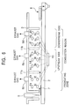
- Fig. 6 is a developed view of a rotary hearth furnace showing another configuration example according to the present invention, and in addition to the configuration shown in Fig. 2, oxygen-containing gas supply devices 9i to 9p for secondary combustion to burn the combustible gas generated by thermal decomposition of the combustible waste 7 and a control device 10 for controlling the quantity of supply of the oxygen-containing gas for secondary combustion are installed in the neighborhood of the rotary hearth 2.
- the range, in which combustion burners 4a to 4b are provided is specified to be a preheating zone
- the range, in which combustion burners 4c to 4h are provided is specified to be a combustion region of the combustible gas.
- the upstream side in the aforementioned combustion region is specified to be the range corresponding to the oxygen-containing gas supply devices 9k to 9m for secondary combustion
- the downstream side in the aforementioned combustion region is specified to be the range corresponding to the oxygen-containing gas supply devices 9n to 9p for secondary combustion.
- an outlet 6c for discharging the exhaust gas generated in the preheating zone and an outlet 6d for discharging the exhaust gas generated in the combustion region are installed.
- chlorine is a flame-retardant material
- the waste containing chlorine is unlikely to burn.
- chlorine can be removed intensively from chlorine-containing combustible waste by thermally decomposing components containing chlorine in the preheating zone in order to dechlorinate, and the dechlorinated combustible waste can undergo combustion treatment in the later combustion region.
- the temperature of the preheating zone is preferably adjusted within the range of 200°C to 600°C. This is because chlorine-based gases rather than combustible gases can be generated intensively by adopting this temperature.
- the lower limit of the temperature is 250°C, and the upper limit of the temperature is 350°C.
- the temperature of the preheating zone must be kept at a relatively low temperature.
- the quantity of heat feed to the burner is adjusted and, in addition, preferably, the surface temperature of the hearth is also taken into consideration. That is, although the hearth in the rotary furnace is heated to a high temperature at the downstream side in the furnace, when the hearth is entered into the preheating zone while that temperature is maintained, the temperature of the preheating zone is raised due to the temperature of the hearth itself and, therefore, the aforementioned temperature range cannot be maintained. Consequently, in the present invention, it is recommended that the temperature of the hearth surface in the preheating zone is controlled with a cooling plate, etc.
- the combustible waste dechlorinated in the preheating zone undergoes combustion treatment in the combustion region installed succeedingly on the side downstream from the preheating zone in a manner similar to that described above.
- the combustible waste dechlorinated is transferred to the upstream side in the combustion region and undergoes combustion treatment in a manner similar to that described above.
- a low proportion of chlorine which has not been able to decompose in the preheating zone, may be included in the gas discharged from the combustion region, and when this gas is burned at a low temperature, there is a possibility of generation of dioxin. Consequently, in order to avoid such a problem, the temperature of the downstream side in the aforementioned combustion region is made to be 850°C or more, and more preferably, be 900°C or more, by the combustion burners 4n to 4h, and the aforementioned gas is desirably held for 2 seconds or more in a chamber kept at the aforementioned temperature. According to that, the aforementioned gas can be substantially burned without generation of dioxin.
- the exhaust gas through the outlet 6d is transferred to the secondary combustion device (for example, secondary combustion chamber), and can be burned completely here.
- the temperature in the secondary combustion chamber is specified to be 850°C or more, and more preferably, be 900°C or more.
- a partition plate 11a is installed vertically from a ceiling portion and, according to this, the chlorine-containing exhaust gas in the preheating zone and the exhaust gas containing no chlorine generated in the combustion region can be efficiently recovered separately as well. Furthermore, in this case, it is also recommended as preferable mode that, as indicated by alternate long and short dashed lines shown in Fig. 6, a partition plate 11b is installed vertically from a ceiling portion and, in addition, an outlet 6e is installed. According to this, the upstream side and the downstream side in the combustion region can be separated, and it becomes easy to recover separately the exhaust gas generated at the upstream side through the outlet 6e, and the exhaust gas generated at the downstream side through the outlet 6d.
- the exhaust gas generated by combustion of the combustible waste has large qualities of thermal energy at a high temperature
- the heat can be recovered.
- the exhaust gas contains corrosive gases, for example, chlorine and hydrogen sulfide, or contains highly volatile metal elements, for example, alkali metals, lead, and zinc
- the heat exchanger is degraded remarkably and, therefore, the heat recovery becomes difficult.
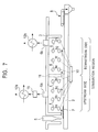
- heat recovery can be performed efficiently by installing a cooling tower 15 and heat exchangers 12a and 12b in addition to the configuration shown in Fig. 5. That is, since in many cases, the aforementioned corrosive gases and highly volatile metal elements are contained in the exhaust gas generated at the upstream side in the combustion region, by supplying the exhaust gas from the outlet 6a to the cooling tower 15, and cooling is performed to on the order of 400°C to 650°C in the cooling tower 15, the corrosive temperature range can be avoided, adhesion can be reduced and, therefore, heat recovery can be performed without degradation of the performance of the heat exchanger 12a.
- the exhaust gas from the outlet 6a can also be supplied into the heat exchanger 12a while that temperature is maintained, and heat recovery can be performed.
- the present invention can meet by adopting the following method.
- the case where the combustible waste contains especially chlorine will be described below, although it is possible to similarly apply to the case where elements other than the aforementioned chlorine are contained.
- a preheating zone and a combustion region are installed, a chlorine-based exhaust gas generated in the preheating zone is discharged to outside the system and, in addition, at least two exhaust gas outlets are installed in the combustion region, the exhaust gas from the outlet installed at the upstream side in the aforementioned combustion region is cooled, and is supplied to the heat exchanger after the temperature is lowered to a proper temperature, a gas separately supplied to the heat exchanger is preheated by the potential heat of the resulting cooled exhaust gas, the resulting preheated gas and the exhaust gas from the outlet installed at the downstream side in the aforementioned combustion region are mixed and, therefore, heat recovery is performed from the resulting gas mixture.
- This method will be described using the drawings.
- Fig. 8 is a developed view of a rotary hearth furnace showing a configuration example when the aforementioned method is put into practice, and in addition to the configuration shown in Fig. 2, oxygen-containing gas supply devices 9i to 9p for secondary combustion to burn the combustible gas generated by thermal decomposition of the combustible waste 7 and a control device 10 for controlling the quantity of supply of the oxygen-containing gas for secondary combustion are installed in the neighborhood of the rotary hearth 2.
- the range, in which combustion burners 4a to 4b are provided is specified to be a preheating zone
- the range, in which combustion burners 4c to 4h are provided is specified to be a combustion region of the combustible gas.
- the upstream side in the aforementioned combustion region is specified to be the range corresponding to the oxygen-containing gas supply devices 9k to 9m for secondary combustion, and the downstream side in the aforementioned combustion region is specified to be the range corresponding to the oxygen-containing gas supply devices 9n to 9p for secondary combustion.
- partition plates 11a and 11b are installed vertically from a ceiling portion in order to individually separate the preheating zone, and the upstream side and the downstream side in the combustion region.
- an outlet 6c for discharging the exhaust gas generated in the preheating zone an outlet 6e for discharging the exhaust gas generated at the upstream side in the combustion region, and an outlet 6d for discharging the exhaust gas generated at the downstream side in the combustion region are provided.
- the chlorine-containing combustible waste supplied into the furnace undergoes dechlorination treatment by being heated in the preheating zone.
- an exhaust gas which degrades the heat exchanger, is also generated at the upstream side in the combustion region. This is because chlorine not completely dechlorinated in the preheating zone remains, or highly volatile metals, etc., are discharged and, therefore, low melting point compounds are formed. Consequently, although the exhaust gas is discharged from the outlet 6e at a high temperature, it is not preferable to supply to the heat exchanger without further treatment and, therefore, cooling to on the order of 400°C to 650°C is performed in the cooling tower 15.
- the resulting cooled exhaust gas is supplied to the heat exchanger 12a, and the gas separately supplied to the heat exchanger 12a is preheated here.
- the gas preheated in the heat exchanger 12a is transferred to a mixer 13, and is mixed with the exhaust gas from the outlet 6d installed at the downstream side in the aforementioned combustion region.
- the temperature of the exhaust gas supplied to the heat exchanger 12b can be adjusted, or it becomes possible to efficiently recover the heat by the heat exchanger 12b without excessive reduction of the temperature of the exhaust gas from the outlet 6d. That is, although it is preferable to supply the exhaust gas to the heat exchanger while being at a high temperature in order to efficiently recover the heat from the exhaust gas, when the temperature is excessively high, the heat exchanger may be damaged. Consequently, the aforementioned preheated gas and the exhaust gas from the outlet 6d are mixed and, therefore, the temperature is adjusted at a proper level without reduction of the total sensible heat.
- the apparatus Since the chlorine concentration in the exhaust gas generated in the preheating zone is high, when this is supplied to the heat exchanger, the apparatus is corroded remarkably. Consequently, the exhaust gas from the preheating zone may be supplied separately to dechlorination equipment 14 and may undergo dechlorination treatment.
- the case where the combustible waste contains chlorine has been described here.
- the aforementioned configuration can be adopted in the case where elements other than chlorine are contained as well.
- the exhaust gas containing elements for example, sulfur, zinc, lead, and alkali metals, may be recovered intensively in the preheating zone and, in addition, heat may be recovered from the exhaust gas generated in the combustion region.
- the combustible waste contains generation sources of a plurality sorts of volatile hazardous components
- the preheating zone may not be included in the configuration, and it is also possible that the exhaust gas from the outlet installed at the upstream side in the combustion region is cooled and is supplied to the heat exchanger so as to preheat the gas, the resulting preheated gas and the exhaust gas from the outlet installed at the downstream side in the combustion region are mixed and, thereafter, the heat is recovered from the resulting gas mixture.
- the target gas for preheating supplied to the aforementioned heat exchanger 12a is not specifically limited as long as it does not bring about problems, for example, corrosion.
- Examples thereof include, for example, combustion exhaust gases, nonoxidative gases, and oxygen-rich gases, and are typified by air.
- Fig. 9 is a sectional view of an apparatus when a rotary hearth furnace is cut in the direction perpendicular to the movement direction of the hearth.
- the nozzle installation position of the oxygen-containing gas supply device 9 for secondary combustion is specified to be 200 mm or more from the hearth 2 and, furthermore, the direction of blowing of the oxygen-containing gas is specified to be horizontal to the hearth or slightly upward the horizontal direction. According to this, since the oxygen-containing gas hardly reaches the neighborhood of the hearth 2, the oxygen potential in the neighborhood of the hearth 2 is reduced and nonoxidative atmosphere is brought about.
- thermal decomposition reaction of the material containing generation sources of the volatile hazardous components proceeds primarily, volatile hazardous components are generated primarily, and the gases are discharged from the outlet 6 to outside the system along the stream of the oxygen-containing gas for secondary combustion. Consequently, the quantity of the volatile hazardous components generated in the combustion region on the side downstream from the preheating zone can be reduced.
- the sort of the burner 4 used in the present invention is not specifically limited, and publicly known burners can be adopted.
- pulverized coal, waste oil, and discarded materials recovered for example, powdery waste plastic, can also be put to effective use as the fuel for the combustion burner.
- the number and installation location of the combustion burners installed in the furnace are not specifically limited as long as the temperature in the furnace can be kept at a predetermined temperature. However, when the inside of the furnace is separated by partition plates vertically installed from the ceiling portion, the temperature in each zone may be controlled by installing at least one combustion burner on a zone basis, and controlling individually the combustion burners.
- the sort of the combustible waste subjected to combustion treatment in the rotary hearth furnace is not specifically limited, and any waste plastic, shredder residue, waste paper, RDF (waste subjected to a treatment for rendering to a solid fuel), etc., discarded as urban refuse, industrial waste or the like can be used.
- examples of combustible waste containing generation sources of volatile hazardous components include waste containing alkali metals, lead, or zinc, those containing chlorine, for example, vinyl chloride resin and vinylidene chloride resin, and those containing sulfur, for example, vulcanized rubber.
- the shape of the combustible waste put into the rotary hearth furnace is not specifically limited as well. However, in consideration of smoothness in putting into the furnace, treatment efficiency, etc., it is preferable that the waste is used after being pulverized into sizes uniform to some extent, or pulverized waste is agglomerated into proper sizes.
- the sizes in this case are preferably specified to be on the order of 6 to 50 mm in diameter.
- shapes of the agglomerated materials include various shapes of, for example, a lump, particle, briquette, pellet, and bar, although, as a matter of course, not limited to these.
- presses for briquetting cylinder press, roll press, ring roller press, etc.
- extruders tumbling granulators
- tumbling granulators pan pelletizer, drum pelletizer, etc.
- other publicly known means can be adopted arbitrarily.
- combustion treatment of the waste can be performed with stability and, in addition, reduction, and melting and separation of metal-based and slug-based residue can also be performed.
- metal oxide for example, iron oxide and/or steel mill waste
- the sort and mixing ratio of the metal oxide in the present invention is not specifically limited. However, it is recommended that the iron-based oxide is contained at 5% by mass or more relative to the agglomerated material put into the furnace, preferably, at 10% by mass or more, and at on the order of 50% to 85% by mass when reduction is intended.
- Combustible waste was subjected to a combustion treatment using an experimental rotary hearth furnace 3.5 m in diameter.
- FIG. 10 A developed view of a rotary hearth furnace used in the experiment developed along the movement direction of a hearth is shown in Fig. 10.
- reference numeral 2 denotes a hearth
- reference numeral 3 denotes a furnace body
- reference numerals 4i to 4l denote combustion burners
- reference numeral 5 denotes a supply port
- reference numerals 6e to 6h denote exhaust gas outlets
- reference numeral 7 denotes combustible waste
- reference numeral 8 denotes a discharge device
- reference numerals 9q to 9t denote oxygen-containing gas supply devices for secondary combustion
- reference numeral 10 denotes a control device for controlling the quantity of supply of the oxygen-containing gas for secondary combustion
- reference numerals 11c to 11e denote partition plates
- reference numeral 16 denotes a rotary leveling apparatus (leveler).
- the inside of the furnace is separated into four zones (first zone to fourth zone) by the partition plates 11c to 11e in order to correspond to the combustion burners 4i to 4l, respectively.
- the first zone and the second zone are controlled individually at 1,200°C
- the third zone and the fourth zone are controlled individually at 1,300°C by the combustion burners.
- Waste plastic having a heating value of about 20 to 30 MJ/kg was made into the shape of a pellet 16 to 20 mm in diameter, and the pellets were put into through the supply port 5 as combustible waste. At this time, in order to heat uniformly the combustible waste in the furnace, the thickness of the combustible waste was adjusted to be 100 mm or less from the hearth by the leveler 16.
- the combustible waste 7 was put into the furnace through the supply port 5 and, in addition, an adequate quantity (1,000 Nm 3 /h) of oxygen-containing gas was supplied individually from the oxygen-containing gas supply devices 9q to 9t for secondary combustion into each of the first to fourth zone.
- the quantity of the combustible waste put into must be 90 kg/h or less in order that the combustible waste undergoes combustion treatment while the temperature in the furnace is maintained as described above to avoid damage to the inside of the furnace due to rapid increase in heating value and, therefore, the treatment efficiency is degraded by a large degree.
- the combustible waste 7 was put into the furnace through the supply port 5 and, in addition, the oxygen-containing gas for secondary combustion was supplied at a modest level from the oxygen-containing gas supply devices 9q to 9t for secondary combustion into each of the first to fourth zone (the first zone was at 720 Nm 3 /h, the second zone was at 320 Nm 3 /h, the third zone was at 320 Nm 3 /h, and the fourth zone was at 160 Nm 3 /h).
- combustion treatment can be performed without fluctuation of the temperature in the furnace. Consequently, in the present invention, the combustible waste can be subjected to the combustion treatment more efficiently than ever with no damage to the inside of the furnace.
- the combustible waste 7 was put into the furnace through the supply port 5 and, in addition, the oxygen-containing gas for secondary combustion was supplied at a modest level into the first zone and the second zone compared to the quantity of oxygen required for burning the combustible gas generated in each zone (the first zone was at 720 Nm 3 /h, and the second zone was at 320 Nm 3 /h).
- the oxygen-containing gas for secondary combustion was supplied in order to burn adequately the combustible gas generated in that zone (the third zone was at 580 Nm 3 /h).
- the oxygen-containing gas for secondary combustion was not supplied, and only the temperature in the zone was adjusted by the combustion burner 4l.
- Combustible waste containing chlorine was subjected to a combustion treatment using the rotary hearth furnace shown in Example 1.
- the inside of the furnace is separated into four zones (first zone to fourth zone) by the partition plates 11c to 11e in order to correspond to the combustion burners 4i to 4l, respectively.
- the first zone was specified to be a preheating zone, and the second to fourth zones were specified to be a combustion region.
- the first zone, second zone, third zone, and fourth zone were controlled at 350°C, 1,000°C, 1,300°C, and 1,300°C, respectively, by the combustion burners.
- the second and third zones are specified to be the upstream side in the combustion region, and the oxygen-containing gas for secondary combustion was supplied at a modest level (320 Nm 3 /h individually).
- the fourth zone is specified to be the downstream side in the combustion region, and the oxygen-containing gas for secondary combustion was supplied adequately (600 Nm 3 /h).
- the chlorine-containing combustible waste contained a vinyl chloride resin, and waste plastic having a heating value of about 20 to 30 MJ/kg was made into the shape of a pellet 16 to 20 mm in diameter. Subsequently, the pellets were put into through the supply port 5.
- Fig. 11 instead of the configuration shown in Fig. 10, the exhaust gas outlets 6e to 6h are not installed, and the exhaust gases generated in the furnace are collectively supplied to an afterburning zone from the downstream side of the furnace.
- An afterburning gas air or oxygen-rich air
- the aforementioned exhaust gases are burned.
- TEQ refers to the Toxic Equivalent
- a mixture of combustible waste and steel mill waste (metal oxide) was agglomerated, was subjected to a combustion treatment in the rotary hearth furnace and, thereafter, the resulting effects were determined.
- a mixture in which the steel mill waste was mixed at a ratio of 1 to 99% by mass relative to the combustible waste was molded into agglomerated materials on the order of diameter 20 ⁇ 30 mm.
- the agglomerated materials were subjected to a combustion treatment in the rotary hearth furnace, and as a result, when the metal oxide mixed into the combustible waste was up to 95% by mass, iron in the residue was reduced and was discharged as reduced iron having a metallization ratio of about 90% or more.
- the maximum temperature in the furnace was able to keep constant at about 1,400°C or less with ease at the upstream side in the combustion region. This is because the heat of combustion of the combustible waste is used for reduction of the metal oxide.
Landscapes
- Engineering & Computer Science (AREA)
- Mechanical Engineering (AREA)
- General Engineering & Computer Science (AREA)
- Chemical & Material Sciences (AREA)
- Combustion & Propulsion (AREA)
- Incineration Of Waste (AREA)
- Gasification And Melting Of Waste (AREA)
- Vertical, Hearth, Or Arc Furnaces (AREA)
- Tunnel Furnaces (AREA)
- Waste-Gas Treatment And Other Accessory Devices For Furnaces (AREA)
- Processing Of Solid Wastes (AREA)
Abstract
Description
Claims (13)
- A method for combustion treatment of combustible waste (7), which is a method for treating combustible waste (7), comprising the step of combustion-treating the combustible waste (7) with a rotary hearth furnace (1).
- The method for combustion treatment according to Claim 1, further comprising the steps of:supplying an oxygen-containing gas for secondary combustion to burn a combustible gas generated by thermal decomposition of the combustible waste (7) in the neighborhood of a hearth (2) of the rotary hearth furnace (1);reducing fluctuation in the heating value by combustion of the combustible gas by controlling the quantity of supply of the oxygen-containing gas for secondary combustion at a modest level at an upstream side in the combustion region of the combustible gas; andburning substantially the combustible gas by supplying adequately the oxygen-containing gas for secondary combustion at a downstream side.
- The method for combustion treatment according to Claim 2, further comprising the step of reducing fluctuation in the heating value by combustion of the combustible gas by controlling the quantity of supply of the oxygen-containing gas for secondary combustion at a modest level in the combustion region.
- The method for combustion treatment according to Claim 2 or Claim 3, further comprising the steps of:installing at least two exhaust gas outlets (6) in the combustion region; anddrawing an exhaust gas generated in the furnace through each of the outlets (6).
- The method for combustion treatment according to Claim 4, further comprising the steps of:cooling the exhaust gas from the outlet (6) installed at the upstream side in the combustion region, supplying to a heat exchanger (12), and performing heat recovery; andperforming heat recovery from the exhaust gas from the outlet (6) installed at the downstream side in the combustion region at a temperature higher than the heat recovery temperature at the upstream side.
- The method for combustion treatment according to Claim 4, further comprising the steps of:cooling the exhaust gas from the outlet (6) installed at the upstream side in the combustion region, supplying to a heat exchanger (12), and preheating a gas; andmixing the resulting preheated gas and the exhaust gas from the outlet (6) installed at the downstream side in the combustion region, and performing heat recovery from the resulting gas mixture.
- The method for combustion treatment according to any one of Claims 1 to 6, wherein the combustible waste (7) generates a volatile hazardous component by heat reduction or thermal decomposition.
- The method for combustion treatment according to Claim 7, further comprising the steps of:installing a preheating zone on the side further upstream from the combustion region;performing a separation treatment of the volatile hazardous component in the preheating zone and drawing a generated exhaust gas containing the volatile hazardous component from the preheating zone.
- An apparatus for combustion treatment of combustible waste (7) which is a rotary hearth furnace (1) for treating combustible waste (7), comprising:an oxygen-containing gas supply device (9) for secondary combustion in order to burn a combustible gas generated by thermal decomposition of the combustible waste (7) in the neighborhood of a hearth (2) of the rotary hearth furnace (1); anda control device (10) for controlling the quantity of supply of the oxygen-containing gas for secondary combustion in the combustion region of the combustible gas.
- The combustion treatment apparatus according to Claim 9, comprising:at least two exhaust gas outlets (6) in the combustion region; anda device for recovering heat from an exhaust gas from each of the outlets (6).
- The combustion treatment apparatus according to Claim 10, comprising:a device for cooling the exhaust gas from the outlet (6) installed at the upstream side in the combustion region;a device for recovering heat from the resulting cooled exhaust gas; anda device for recovering heat from the exhaust gas from the outlet (6) installed at the downstream side in the combustion region.
- The combustion treatment apparatus according to Claim 10, comprising:a device for cooling the exhaust gas from the outlet (6) installed at the upstream side in the combustion region;a device for preheating a gas by the heat from the resulting cooled exhaust gas;a device for mixing the gas preheated by the preheating device with the exhaust gas from the outlet installed at the downstream side in the combustion region; anda device for recovering heat from the resulting gas mixture.
- The combustion treatment apparatus according to any one of Claims 9 to 12, wherein:the combustible waste (7) contains a generation source of a volatile hazardous component;a preheating zone is installed on the side further upstream from the combustion region; andan outlet (6) for discharging an exhaust gas containing a volatile hazardous component generated in the preheating zone is installed.
Applications Claiming Priority (2)
| Application Number | Priority Date | Filing Date | Title |
|---|---|---|---|
| JP2001251831A JP3961795B2 (en) | 2001-08-22 | 2001-08-22 | Combustion treatment method and apparatus for combustible waste |
| JP2001251831 | 2001-08-22 |
Publications (2)
| Publication Number | Publication Date |
|---|---|
| EP1286114A2 true EP1286114A2 (en) | 2003-02-26 |
| EP1286114A3 EP1286114A3 (en) | 2003-05-21 |
Family
ID=19080413
Family Applications (1)
| Application Number | Title | Priority Date | Filing Date |
|---|---|---|---|
| EP02018401A Withdrawn EP1286114A3 (en) | 2001-08-22 | 2002-08-14 | Method for combustion treatment of combustible waste and apparatus used therefor |
Country Status (5)
| Country | Link |
|---|---|
| US (1) | US7032526B2 (en) |
| EP (1) | EP1286114A3 (en) |
| JP (1) | JP3961795B2 (en) |
| CA (1) | CA2397312A1 (en) |
| TW (1) | TW536429B (en) |
Cited By (2)
| Publication number | Priority date | Publication date | Assignee | Title |
|---|---|---|---|---|
| FR2917486A1 (en) * | 2007-06-15 | 2008-12-19 | Ct Internat De Traitement Et D | PROCESS FOR GASIFYING WASTE IN A ROTATING SOAK OVEN, AND OVEN FOR ITS IMPLEMENTATION |
| EP2093300A4 (en) * | 2006-11-14 | 2011-09-21 | Kobe Steel Ltd | Process for production of granular metallic iron and equipment for the production |
Families Citing this family (19)
| Publication number | Priority date | Publication date | Assignee | Title |
|---|---|---|---|---|
| DE19960075A1 (en) * | 1999-12-13 | 2001-07-05 | Krc Umwelttechnik Gmbh | High pressure gasification of wastes and residues containing halogens comprises bringing raw gas into contact with water and evaporating water to saturate gas with steam |
| US7191450B2 (en) * | 2003-02-06 | 2007-03-13 | International Business Machines Corporation | Data-driven application integration adapters |
| JP4490640B2 (en) * | 2003-02-26 | 2010-06-30 | 株式会社神戸製鋼所 | Method for producing reduced metal |
| US8034283B2 (en) * | 2005-10-31 | 2011-10-11 | Kobe Steel, Ltd. | Rotary hearth furnace and method of operating the same |
| PT2148135E (en) * | 2008-07-25 | 2013-07-30 | Litesso Anstalt | Method and device for thermal processing of waste material |
| US8163230B2 (en) * | 2008-08-29 | 2012-04-24 | Global Research and Engineering, LLC | Rotary hearth furnace for treating metal oxide materials |
| WO2011041431A1 (en) | 2009-09-29 | 2011-04-07 | Nu-Iron Technology, Llc | System and method for producing metallic iron |
| TWI458921B (en) * | 2011-07-29 | 2014-11-01 | Scandinavian Biofuel Company As | A novel microwave assisted flash pyrolysis system and method using the same |
| JP2013204971A (en) * | 2012-03-29 | 2013-10-07 | Hitachi Zosen Corp | Method for pre-treatment of waste |
| JP2015013764A (en) * | 2013-07-03 | 2015-01-22 | 住友電気工業株式会社 | Manufacturing method of glass base material |
| CN104266480A (en) * | 2014-10-28 | 2015-01-07 | 永兴县荣鹏金属有限公司 | Gas supply device of smelting reverberating furnace |
| CN108716852A (en) * | 2018-06-13 | 2018-10-30 | 佛山市中晨窑炉设备有限公司 | A kind of kiln firing oxidation panel secondary combustion system |
| GB2585870B (en) | 2019-07-18 | 2024-06-19 | Powerhouse Energy Group Plc | Treatment of waste material |
| GB2585873A (en) * | 2019-07-18 | 2021-01-27 | Powerhouse Energy Group Plc | Treatment of waste material |
| GB2585872A (en) | 2019-07-18 | 2021-01-27 | Powerhouse Energy Group Plc | Treatment of waste material |
| CN110982554B (en) * | 2019-12-25 | 2024-07-26 | 中国成达工程有限公司 | Acetylene-containing carbide slag tail gas treatment system in process of producing acetylene by carbide dry method |
| GB2595727A (en) | 2020-06-05 | 2021-12-08 | Edwards Ltd | Inlet assembly |
| CN113145611A (en) * | 2021-04-02 | 2021-07-23 | 张凯 | Method for cooperatively treating organic hazardous waste by utilizing coal combustion equipment |
| AT525741B1 (en) * | 2022-04-20 | 2023-07-15 | Iaf Process Eng Gmbh | PROCESS AND SYSTEM FOR WASTE HEAT RECOVERY |
Family Cites Families (40)
| Publication number | Priority date | Publication date | Assignee | Title |
|---|---|---|---|---|
| US227651A (en) * | 1880-05-18 | Ditching-machine | ||
| DE645759C (en) * | 1937-06-02 | Curt Doerschel Dr Ing | Ring furnace with rotary hearth for incinerating garbage | |
| US241937A (en) * | 1881-05-24 | Tide-water elevator | ||
| US1913088A (en) * | 1930-10-03 | 1933-06-06 | William W Ridgely | Air feeding system for coal burners |
| US3443931A (en) | 1965-09-10 | 1969-05-13 | Midland Ross Corp | Process for making metallized pellets from iron oxide containing material |
| GB1229329A (en) * | 1968-06-08 | 1971-04-21 | ||
| US3575119A (en) * | 1968-07-05 | 1971-04-13 | Andrew W Marr Jr | Electrical arc apparatus for disintegrating and incinerating a slurry organic material |
| BE756970A (en) * | 1969-10-02 | 1971-03-16 | Atomenergi Ab | IMPROVEMENTS FOR INCINERATORS, ESPECIALLY OF GARBAGE |
| DE2026970A1 (en) * | 1969-10-03 | 1971-04-22 | Tvtr Meissner, W , Dipl Ing , Tischer, H , Dipl Ing, Pat Anwalte, 1000 Berlin und 8000 München | Method and device for incinerating plastic waste |
| DE2063628C3 (en) * | 1970-06-12 | 1974-05-09 | Iwatani & Co., Ltd., Osaka (Japan) | Incinerator for waste oil |
| US3716002A (en) * | 1971-04-01 | 1973-02-13 | Stearns Roger Corp | Solid waste disposal method and apparatus |
| FR2135885A5 (en) * | 1971-04-30 | 1972-12-22 | Sigoure Freres Chaudronn | |
| US4063903A (en) * | 1975-09-08 | 1977-12-20 | Combustion Equipment Associates Inc. | Apparatus for disposal of solid wastes and recovery of fuel product therefrom |
| FR2495736A1 (en) * | 1980-12-05 | 1982-06-11 | Air Liquide | METHOD AND PLANT FOR TREATING ENERGY RECOVERED WASTE |
| US4452153A (en) * | 1982-01-19 | 1984-06-05 | Midland-Ross Corporation | Rotary hearth pyrolyzer with tapered spreader roll |
| US4602573A (en) * | 1985-02-22 | 1986-07-29 | Combustion Engineering, Inc. | Integrated process for gasifying and combusting a carbonaceous fuel |
| NZ222007A (en) * | 1986-10-02 | 1989-01-27 | Neutralysis Ind Pty Ltd | Treating waste material by pelletising and vitrifying |
| IT1210422B (en) * | 1987-04-17 | 1989-09-14 | Marangoni Meccanica | SYSTEM FOR THE GENERATION OF WATER STEAM FOR COGENERATIVE SYSTEMS, THROUGH PYROLYSIS OF WHOLE TIRES, SELF-CLEANING AND AUTOMATIC REVIVAL OF COMBUSTION THROUGH A PARTICULAR GEOMETRIC AND CINEMATIC CONFERENCE OF THE COMBUSION TANK. |
| FR2614394B1 (en) * | 1987-04-24 | 1989-07-28 | Idee Sarl | INCINERATION OVEN WITH A ROTATING SOLE AROUND A VERTICAL AXIS |
| US5254797A (en) * | 1989-06-07 | 1993-10-19 | Ngk Insulators, Ltd. | Method of treating exhaust gas |
| US5005493A (en) * | 1989-11-08 | 1991-04-09 | American Combustion, Inc. | Hazardous waste multi-sectional rotary kiln incinerator |
| US5102330A (en) * | 1990-03-29 | 1992-04-07 | Union Carbide Industrial Gases Technology Corporation | Opposed fired rotary kiln |
| US5138957A (en) * | 1991-05-15 | 1992-08-18 | Biotherm Energy Systems, Inc. | Hot gas generation system for producing combustible gases for a burner from particulate solid organic biomass material |
| US5885521A (en) | 1994-12-16 | 1999-03-23 | Midrex International B.V. Rotterdam, Zurich Branch | Apparatus for rapid reduction of iron oxide in a rotary hearth furnace |
| AUPN585795A0 (en) * | 1995-10-06 | 1995-11-02 | Tox Free Systems Inc. | Volatile materials treatment system |
| DE69624073T2 (en) | 1995-11-28 | 2003-08-14 | Ebara Corp., Tokio/Tokyo | Process and device for treating waste by gasification |
| JP3296974B2 (en) | 1996-08-15 | 2002-07-02 | 株式会社神戸製鋼所 | Direct reduction method and rotary bed furnace |
| JPH10195513A (en) | 1996-12-27 | 1998-07-28 | Kobe Steel Ltd | Manufacturing method of metallic iron |
| US6149709A (en) | 1997-09-01 | 2000-11-21 | Kabushiki Kaisha Kobe Seiko Sho | Method of making iron and steel |
| TW495552B (en) | 1997-12-18 | 2002-07-21 | Kobe Steel Ltd | Method of producing reduced iron pellets |
| JP3081581B2 (en) | 1998-03-23 | 2000-08-28 | 株式会社神戸製鋼所 | Method of producing reduced iron agglomerates with high metallization rate |
| EP0952230A1 (en) | 1998-03-24 | 1999-10-27 | KABUSHIKI KAISHA KOBE SEIKO SHO also known as Kobe Steel Ltd. | Method of producing reduced iron agglomerates |
| JP2997459B1 (en) | 1998-11-04 | 2000-01-11 | 株式会社神戸製鋼所 | Method for producing reduced iron agglomerates |
| ZA995438B (en) | 1998-08-27 | 2000-03-20 | Kobe Steel Ltd | Method for operating moving hearth reducing furnace. |
| JP3004265B1 (en) | 1998-11-24 | 2000-01-31 | 株式会社神戸製鋼所 | Carbon material interior pellet and reduced iron production method |
| JP3404309B2 (en) | 1999-01-18 | 2003-05-06 | 株式会社神戸製鋼所 | Method and apparatus for producing reduced iron agglomerates |
| JP3009661B1 (en) | 1999-01-20 | 2000-02-14 | 株式会社神戸製鋼所 | Method for producing reduced iron pellets |
| CN1219891C (en) | 1999-05-06 | 2005-09-21 | 株式会社神户制钢所 | Direct reduction method and rotary kiln hearth |
| US6368104B1 (en) * | 1999-09-24 | 2002-04-09 | The Boc Group, Inc. | Rotary hearth furnace |
| CN1258605C (en) | 1999-10-15 | 2006-06-07 | 株式会社神户制钢所 | Reduced metal manufacturing equipment and reduced metal manufacturing method |
-
2001
- 2001-08-22 JP JP2001251831A patent/JP3961795B2/en not_active Expired - Fee Related
-
2002
- 2002-08-07 TW TW091117751A patent/TW536429B/en not_active IP Right Cessation
- 2002-08-09 CA CA002397312A patent/CA2397312A1/en not_active Abandoned
- 2002-08-14 EP EP02018401A patent/EP1286114A3/en not_active Withdrawn
- 2002-08-20 US US10/223,367 patent/US7032526B2/en not_active Expired - Fee Related
Cited By (4)
| Publication number | Priority date | Publication date | Assignee | Title |
|---|---|---|---|---|
| EP2093300A4 (en) * | 2006-11-14 | 2011-09-21 | Kobe Steel Ltd | Process for production of granular metallic iron and equipment for the production |
| US8377169B2 (en) | 2006-11-14 | 2013-02-19 | Kobe Steel, Ltd. | Method and apparatus for manufacturing granular metallic iron |
| US8617459B2 (en) | 2006-11-14 | 2013-12-31 | Kobe Steel, Ltd. | Method and apparatus for manufacturing granular metallic iron |
| FR2917486A1 (en) * | 2007-06-15 | 2008-12-19 | Ct Internat De Traitement Et D | PROCESS FOR GASIFYING WASTE IN A ROTATING SOAK OVEN, AND OVEN FOR ITS IMPLEMENTATION |
Also Published As
| Publication number | Publication date |
|---|---|
| CA2397312A1 (en) | 2003-02-22 |
| JP2003065519A (en) | 2003-03-05 |
| JP3961795B2 (en) | 2007-08-22 |
| TW536429B (en) | 2003-06-11 |
| US20030037714A1 (en) | 2003-02-27 |
| EP1286114A3 (en) | 2003-05-21 |
| US7032526B2 (en) | 2006-04-25 |
Similar Documents
| Publication | Publication Date | Title |
|---|---|---|
| US7032526B2 (en) | Method for combustion treatment of combustible waste and apparatus therefor | |
| RU2086869C1 (en) | Method for continuous preliminary heating of charge materials for steel melting furnace and plant for realization of this method | |
| EP1896774B1 (en) | Waste treatment process and apparatus | |
| EP0442040B1 (en) | Method and apparatus for direct reduction of metal oxides | |
| CN111853798A (en) | Incinerator for treating waste and method for treating waste using the same | |
| WO2002021047A1 (en) | Waste-gasified fusion furnace and method of operating the fusion furnace | |
| JP4525009B2 (en) | Waste disposal by rotary kiln | |
| WO2003062474A1 (en) | Process for producing molten iron | |
| JP2000192129A (en) | Converter operation method | |
| CA2366290C (en) | A method and apparatus for reducing a feed material in a rotary hearth furnace | |
| EP0747492B1 (en) | Method for melting ferrous metals by means of an electric arc furnace charged with ferrous materials containing energy-releasing substances | |
| KR100259970B1 (en) | Scrap melting | |
| JP3940366B2 (en) | Liquid iron manufacturing method | |
| EP0846919B1 (en) | Burning/melting method of waste melting furnace | |
| JP4734776B2 (en) | Organic or hydrocarbon waste recycling method and blast furnace equipment suitable for recycling | |
| JP2001317717A (en) | Oil impregnated sludge incinerator and oil impregnated sludge firing method | |
| KR100551269B1 (en) | Waste heat recovery heat storage method of waste pyrolysis melting furnace | |
| JP3806253B2 (en) | Waste plastic blowing method to waste melting furnace | |
| JP2000171019A (en) | Waste treatment equipment | |
| JP2002363626A (en) | Operating method of moving hearth furnace | |
| JP3984484B2 (en) | Shredder dust melting method | |
| WO2023054552A1 (en) | Melting furnace and method for operating melting furnace | |
| JP3732013B2 (en) | Waste plastic injection into waste melting furnace | |
| JPH02217788A (en) | Scrap melting method in arc electric furnace and arc electric furnace for scrap melting | |
| JP3293431B2 (en) | Scrap melting method |
Legal Events
| Date | Code | Title | Description |
|---|---|---|---|
| PUAI | Public reference made under article 153(3) epc to a published international application that has entered the european phase |
Free format text: ORIGINAL CODE: 0009012 |
|
| AK | Designated contracting states |
Kind code of ref document: A2 Designated state(s): AT BE BG CH CY CZ DE DK EE ES FI FR GB GR IE IT LI LU MC NL PT SE SK TR Designated state(s): AT BE BG CH CY CZ DE DK EE ES FI FR GB GR IE IT LI LU MC NL PT SE SK TR |
|
| AX | Request for extension of the european patent |
Extension state: AL LT LV MK RO SI |
|
| PUAL | Search report despatched |
Free format text: ORIGINAL CODE: 0009013 |
|
| AK | Designated contracting states |
Designated state(s): AT BE BG CH CY CZ DE DK EE ES FI FR GB GR IE IT LI LU MC NL PT SE SK TR |
|
| AX | Request for extension of the european patent |
Extension state: AL LT LV MK RO SI |
|
| 17P | Request for examination filed |
Effective date: 20030731 |
|
| AKX | Designation fees paid |
Designated state(s): AT BE BG CH CY CZ DE DK EE ES FI FR GB GR IE IT LI LU MC NL PT SE SK TR |
|
| 17Q | First examination report despatched |
Effective date: 20041123 |
|
| STAA | Information on the status of an ep patent application or granted ep patent |
Free format text: STATUS: THE APPLICATION IS DEEMED TO BE WITHDRAWN |
|
| 18D | Application deemed to be withdrawn |
Effective date: 20050805 |