EP1286036A2 - Method for influencing the nocuous substance emission and/or the noise emission of an internal combustion engine and fuel injection device - Google Patents
Method for influencing the nocuous substance emission and/or the noise emission of an internal combustion engine and fuel injection device Download PDFInfo
- Publication number
- EP1286036A2 EP1286036A2 EP02016001A EP02016001A EP1286036A2 EP 1286036 A2 EP1286036 A2 EP 1286036A2 EP 02016001 A EP02016001 A EP 02016001A EP 02016001 A EP02016001 A EP 02016001A EP 1286036 A2 EP1286036 A2 EP 1286036A2
- Authority
- EP
- European Patent Office
- Prior art keywords
- fuel
- injection quantity
- injection system
- fuel injection
- plateau
- Prior art date
- Legal status (The legal status is an assumption and is not a legal conclusion. Google has not performed a legal analysis and makes no representation as to the accuracy of the status listed.)
- Granted
Links
Images


Classifications
-
- F—MECHANICAL ENGINEERING; LIGHTING; HEATING; WEAPONS; BLASTING
- F02—COMBUSTION ENGINES; HOT-GAS OR COMBUSTION-PRODUCT ENGINE PLANTS
- F02D—CONTROLLING COMBUSTION ENGINES
- F02D41/00—Electrical control of supply of combustible mixture or its constituents
- F02D41/008—Controlling each cylinder individually
- F02D41/0087—Selective cylinder activation, i.e. partial cylinder operation
-
- F—MECHANICAL ENGINEERING; LIGHTING; HEATING; WEAPONS; BLASTING
- F02—COMBUSTION ENGINES; HOT-GAS OR COMBUSTION-PRODUCT ENGINE PLANTS
- F02D—CONTROLLING COMBUSTION ENGINES
- F02D41/00—Electrical control of supply of combustible mixture or its constituents
- F02D41/30—Controlling fuel injection
- F02D41/38—Controlling fuel injection of the high pressure type
- F02D41/3809—Common rail control systems
-
- F—MECHANICAL ENGINEERING; LIGHTING; HEATING; WEAPONS; BLASTING
- F02—COMBUSTION ENGINES; HOT-GAS OR COMBUSTION-PRODUCT ENGINE PLANTS
- F02M—SUPPLYING COMBUSTION ENGINES IN GENERAL WITH COMBUSTIBLE MIXTURES OR CONSTITUENTS THEREOF
- F02M63/00—Other fuel-injection apparatus having pertinent characteristics not provided for in groups F02M39/00 - F02M57/00 or F02M67/00; Details, component parts, or accessories of fuel-injection apparatus, not provided for in, or of interest apart from, the apparatus of groups F02M39/00 - F02M61/00 or F02M67/00; Combination of fuel pump with other devices, e.g. lubricating oil pump
- F02M63/02—Fuel-injection apparatus having several injectors fed by a common pumping element, or having several pumping elements feeding a common injector; Fuel-injection apparatus having provisions for cutting-out pumps, pumping elements, or injectors; Fuel-injection apparatus having provisions for variably interconnecting pumping elements and injectors alternatively
- F02M63/0225—Fuel-injection apparatus having a common rail feeding several injectors ; Means for varying pressure in common rails; Pumps feeding common rails
Definitions
- the present invention relates to a method for Influencing the pollutant emission values and / or the Noise levels of a fuel injection system having internal combustion engine, in particular of a diesel engine, the fuel injection system has a plurality of injectors, which are provided with appropriate control through a control device, fuel into the cylinders of the internal combustion engine. Furthermore concerns the present invention a fuel injection system for an internal combustion engine, in particular for a diesel engine, the fuel injection system having a plurality of injectors intended to with appropriate control by a control device, Fuel into the cylinders of the internal combustion engine inject.
- the Pressure generation and injection decoupled from each other are the Pressure generation and injection decoupled from each other.
- the injection pressure becomes independent of the engine speed and the injection quantity generated and is in a fuel reservoir ready for injection.
- the Injection time and the injection quantity are in one electronic control unit and calculated by an injector or an injection unit on each engine cylinder implemented via a controlled solenoid valve.
- pre-injection in which a small amount of fuel, in particular diesel fuel, is introduced into the cylinder before the so-called main injection, with which the energy for the engine's work is introduced.
- the amount of fuel introduced into the cylinder during the pre-injection can be, for example, between 1 mm 3 and 4 mm 3 .
- This pre-injection causes the combustion chamber to be preconditioned, improves the combustion efficiency and can also achieve the following effects: the compression pressure is slightly increased by a pre-reaction or partial combustion, which shortens the ignition delay of the main injection and reduces the increase in combustion pressure and the combustion pressure peaks, which leads to a so-called soft combustion.
- injection quantity control duration characteristic curves differ at least slightly in practice, even with identical injectors. This applies in particular to small injection quantities and is due to manufacturing tolerances and / or component tolerances.
- the differences in the injection quantity control duration characteristic curves can lead to the fact that specified limit values, for example particle emission limit values and noise level limit values, cannot be met, since a control that is optimal for one injector is not optimal for another injector.
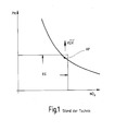
- Figure 1 shows the known relationship between the Particle emission and the emission of nitrogen oxides for a diesel engine by varying the exhaust gas recirculation rate occurs with constant start of spraying.
- This Curve shows that there is a reduction in particle emissions to an increase in nitrogen oxide emissions leads and vice versa.
- the choice of an operating point AP is therefore always a compromise, which is why the in FIG. 1 relationship also shown as a "trade-off" referred to as.
- Emission limit values EG both for particle emission as well as for the emission of nitrogen oxides it is therefore necessary to set the operating point AP in suitably on the curve shown in Figure 1 to postpone. By increasing the pre-injection quantity the trade-off is shifted according to the arrow.
- FIG. 2 shows a characteristic field known per se, which illustrates the injection quantity EM as a function of the injection period T for different pressures p s in the fuel accumulator. It can be seen from the curve profiles in FIG. 2 that the curves have a plateau P in the region of short activation times. In the area of a plateau P, the curve runs approximately parallel to the actuation duration axis, that is to say in the area of a plateau P, it is not possible to change the injection quantity by changing the actuation duration. Typically, however, the pre-injections are carried out precisely in the map region of the plateaus P.
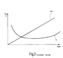
- Figure 3 shows the known relationship between Pre-injection quantity VEM and particle emission PM as well as noise G. The goal is to optimize noise or a tolerable increase in smoke.
- the assignment of the plurality of injectors according to the invention to a respective fuel injection system thereby done by the injectors after their manufacture first be divided into classes by the Course of the characteristic curves of the Depend on the injection quantity control duration characteristic.
- This Characteristic curves are possibly suitable Determine test and measurement procedures.
- the preferred on all injectors of a corresponding fuel injection system applied in the same way adaptive Measures make it possible in combination with the use predefined by injectors assigned to a class Comply with emission limit values and noise level limit values or at least improve it.
- the method provides that the at least one predetermined section of the injection quantity control duration characteristic that used for a fuel pre-injection Characteristic section includes.
- Fuel injection systems with injectors that are different Inject fuel quantities during fuel pre-injection do it in the state of the art in many Cases impossible to meet the specified limit values, because the one injected during the pre-injection Amount of fuel both based on pollutant emissions also has a strong impact on the noise level, as initially mentioned has already been explained in more detail.
- the use of Injectors, at least in this characteristic range have approximately the same properties for one Fuel injection system is therefore particularly advantageous.
- the inventive Procedures continue to be provided that the at least one predetermined section of the injection quantity control duration characteristic a plateau of the injection quantity control duration characteristic includes one Change in the control duration at least not a significant one Changes in the injection quantity causes.
- the the plateau characteristic curve section is particularly critical because within this characteristic section, as mentioned above a change in injection duration in the prior art at least no significant change in the injection quantity can be effected, which is why the use of injectors with the same or at least as possible similar plateaus for a fuel injection system is particularly advantageous.
- the at least one adaptive measure that includes the pressure in one of the fuel injection systems assigned fuel storage changed becomes. Because the fuel reservoir is preferably with everyone Connected to injectors, a change affects of the pressure in this fuel reservoir on the Injection behavior of all injectors. Since the mentioned Controller also controls the pressure in the fuel accumulator controls, the setting of this pressure, for example by suitable programming of the control device respectively.
- control respectively Control device is within the present application to be understood in such a way that it also regulates respectively Control equipment includes.
- the method according to the invention sees fuel storage preferably further before that the pressure in which the Fuel injection system assigned fuel storage is increased to reduce smoke formation, if the pre-injection volume plateau is of a relatively high Pre-injection quantity corresponds.
- the method according to the invention looks in a similar way in this regard, the pressure in which the Fuel injection system assigned fuel storage is reduced if the pre-injection quantity plateau corresponds to a relatively low pre-injection quantity.
- the inventive method can be an adaptive measure continue to provide that the at least one adaptive Measure includes changing an exhaust gas recirculation rate becomes.
- the setting of the exhaust gas recirculation rate can also through suitable programming of the motor control take place, for example, by the control device mentioned can be carried out.
- the method according to the invention further proposes that the EGR rate be reduced if the pre-injection quantity plateau of a relatively high pre-injection quantity equivalent.
- the method according to the invention looks in a similar way in this context, preferably also before that the EGR rate is increased when the pilot injection quantity plateau a relatively low pre-injection quantity equivalent.
- an adaptive measure includes a start of control the injectors are changed.
- the change in Control of the injectors can be either one Fuel pre-injection as well as a main fuel injection affect. Also the change in the start of control the injectors can be programmed appropriately the control device.
- the method according to the invention preferably further provides that the start of activation for a pre-injection is postponed early or late depending on the position of the starting point on the NO x / PM trade-off.
- the direction depends on the emission target to be achieved. If, for example, a NO x reduction is aimed for, then it is advisable to adapt the start of control late, and if soot is aimed for, it is advisable to adapt the start of control early.
- the fuel injection system according to the invention is based on the generic prior art in that to influence the pollutant emission values and / or the noise emission values of the internal combustion engine Most of the injectors in at least one predetermined Section of the injection quantity control duration characteristic has at least approximately the same characteristic curves, the control of the injectors by the control device influenced by at least one adaptive measure is that of approximately the same characteristic curves depends. In this way, the pollutant emission values and / or the noise emission values in the Be lowered compared to the prior art and it is in many cases, for example, by the legislator to comply with specified limit values.
- the at least one adaptive Measure is preferably through appropriate programming the control device realized.
- the control device control algorithms includes the at least one adaptive measure if necessary, during the service life of the internal combustion engine adapted to wear or other sizes become.
- the at least one predetermined Section of the injection quantity control duration characteristic that used for a fuel pre-injection Characteristic section includes. Similar to that The method according to the invention also applies here: fuel injection systems with injectors that are different Fuel quantities in a fuel pre-injection inject, do it in the state of the art in many Cases impossible to meet the specified limit values, because the one injected during the pre-injection Amount of fuel both based on pollutant emissions also has a strong impact on the noise level, as initially mentioned has already been explained in more detail.
- the use of Injectors, at least in this characteristic range have approximately the same properties for one Fuel injection system is therefore particularly advantageous.
- the at least one predetermined section of the injection quantity control duration characteristic a plateau of the injection quantity control duration characteristic includes a change in the control duration at least no significant change in the injection quantity causes.
- the characteristic curve section forming a plateau is particularly critical, because within this section of the characteristic curve about a change the injection duration in the prior art at least no significant change in the injection quantity can be effected. Therefore it is also related to the fuel injection systems according to the invention Use of injectors with the same or at least with similar plateaus for a fuel injection system particularly advantageous.
- Fuel storage is increased to prevent smoke from forming decrease if the pilot injection quantity plateau is one corresponds to a relatively high pre-injection quantity.
- the Fuel injection system according to the invention in this Continue to provide that the pressure in the the fuel storage system associated with the fuel injection system is reduced if the pre-injection quantity plateau corresponds to a relatively low pre-injection quantity.
- Fuel injection system should be provided that the at least one adaptive measure includes an exhaust gas recirculation rate is changed.
- a corresponding change The exhaust gas recirculation rate can also be used in this context by programming the control device accordingly respectively.
- the exhaust gas recirculation rate is reduced if the pre-injection quantity plateau corresponds to a relatively high pre-injection quantity.
- the at least one adaptive measure in addition or as an alternative to one or both of the adaptive measures explained above includes changing the start of actuation of the injectors becomes.
- a corresponding change in the start of control can be restored by programming the Control device can be achieved.
- the start of activation for a pre-injection is postponed early or late depending on the position of the starting point on the NO x / PM trade-off.
- the direction depends on the emission target to be achieved. If, for example, a NO x reduction is aimed for, then it is advisable to adapt the start of control late, and if soot is aimed for, it is advisable to adapt the start of control early.
- the invention is therefore based on the knowledge that through the use of classified injectors at least very similar characteristic curves, in particular in the range of the characteristic curve for the pre-injection is used, and performing appropriate adaptive measures, in particular through suitable Programming of the control device can be realized can, in many cases, limit values for pollutant emission values and / or the noise emission values are complied with can be.
- FIG. 4 shows the dependence of the particle emission PM and the noise level G on the pre-injection quantity VEM.
- the vertical corridor drawn around the pre-injection quantity VEM 2 is the corridor for reaching the emission target (nominal design).
- the arrow pointing from right to left illustrates a first strategy for a high pre-injection quantity, while the arrow pointing from left to right illustrates a second strategy for a low pre-injection quantity. If injectors 131 with a relatively low pre-injection quantity VEM 1 are used, it can be accepted that the actually resulting noise level is shifted into a target range TARGET, which still complies with legal requirements by carrying out at least one adaptive measure.
- the shift in the pollutant emission values and / or the noise emission values can take place in particular by reducing the pressure p s in the fuel accumulator 130 assigned to the fuel injection system 10 by increasing the exhaust gas recirculation rate a pre-injection is postponed early or late depending on the location of the starting point on the NO x / PM trade-off. The direction depends on the emission target to be achieved.
- FIG. 4 also shows an area around a normal pilot injection VEM 2 , which does not require any adaptive measures.
- the at least one adaptive measure can in particular provide that the pressure p s in a fuel accumulator assigned to the fuel injection system 10. 130 is increased, that the exhaust gas recirculation rate is reduced.
- the start of activation for a pre-injection is postponed early or late depending on the position of the starting point on the NO x / PM trade-off. The direction depends on the emission target to be achieved. If, for example, a NO x reduction is aimed for, then it is advisable to adapt the start of control late, and if soot is aimed for, it is advisable to adapt the start of control early.
- FIG. 5 shows a block diagram of an embodiment the fuel injection system according to the invention.
- the illustrated Fuel injection system 10 is usually also called Common rail system.
- the fuel tank 100 is a fuel tank.
- the fuel tank 100 stands over a first filter 105 and one Pre-feed pump 110 with a second filter means 115 in Connection. From the second filter means 115 Fuel via a line to a high pressure pump 125.
- the connecting line between the filter means 115 and the high pressure pump 125 is above a low pressure relief valve 145 in connection with the fuel tank 100.
- the high pressure pump 125 is available with a rail or fuel accumulator 130 connected.
- the rail 130 protrudes Fuel lines with various injectors 131 in Contact.
- the rail 130 is via a pressure relief valve 135 connectable to the fuel tank 100.
- the pressure relief valve 135 can be controlled by means of a coil 136.
- the lines between the outlet of the high pressure pump 125 and the input of the pressure lock valve 135 are considered High pressure area designated. In this area is the High pressure fuel.
- the pressure in the high pressure area is detected by means of a sensor 140.
- the lines between tank 100 and high pressure pump 125 are called the low pressure range.
- a controller 160 via which the adaptive according to the invention Measures are implemented, the High pressure pump 125 with a control signal AP, the injectors 131 with a control signal A and / or that Pressure relief valve 135 with a control signal AV.
- the Controller 160 processes various signals various sensors 165, which determine the operating state of the Internal combustion engine and / or the motor vehicle that the Internal combustion engine drives, characterize. Such a The operating state is, for example, the speed N the internal combustion engine.
- the fuel, the located in the fuel tank 100 is from the Pre-feed pump 110 through filter means 105 and 115 promoted.
- the low pressure relief valve opens 145 and gives the connection between the exit of the Pre-feed pump 110 and the fuel tank 100 free.
- the high pressure pump 125 delivers the amount of fuel Q1 from Low pressure area in the high pressure area.
- the high pressure pump 125 builds a very high pressure in the Rail 130 on.
- pressure values from about 30 to 100 bar and compression ignition internal combustion engines achieved about 1000 to 2000 bar.
- the injectors 131 the fuel can be under high pressure to the individual cylinders be metered to the internal combustion engine.
- the pressure p s in the rail or in the entire high-pressure range is detected by means of the sensor 140.
- the pressure in the high pressure region is regulated by means of the controllable high pressure pump 125 and / or the pressure relief valve 135.
- Electric fuel pumps are usually used as the feed pump 110 used.
- the feed pump 110 For higher flow rates, the are particularly necessary for commercial vehicles, can also use several pre-feed pumps connected in parallel be used.
Landscapes
- Engineering & Computer Science (AREA)
- Chemical & Material Sciences (AREA)
- Combustion & Propulsion (AREA)
- Mechanical Engineering (AREA)
- General Engineering & Computer Science (AREA)
- Electrical Control Of Air Or Fuel Supplied To Internal-Combustion Engine (AREA)
- Fuel-Injection Apparatus (AREA)
- Output Control And Ontrol Of Special Type Engine (AREA)
- Combined Controls Of Internal Combustion Engines (AREA)
- Exhaust-Gas Circulating Devices (AREA)
Abstract
Description
Die vorliegende Erfindung betrifft ein Verfahren zur Beeinflussung der Schadstoffemissionswerte und/oder der Geräuschemissionswerte eines eine Kraftstoff-Einspritzanlage aufweisenden Verbrennungsmotors, insbesondere eines Dieselmotors, wobei die Kraftstoff-Einspritzanlage eine Mehrzahl von Injektoren aufweist, die dazu vorgesehen sind, bei entsprechender Ansteuerung durch eine Steuereinrichtung, Kraftstoff in die Zylinder des Verbrennungsmotors einzuspritzen. Weiterhin betrifft die vorliegende Erfindung eine Kraftstoff-Einspritzanlage für einen Verbrennungsmotor, insbesondere für einen Dieselmotor, wobei die Kraftstoff-Einspritzanlage eine Mehrzahl von Injektoren umfasst, die dazu vorgesehen sind, bei entsprechender Ansteuerung durch eine Steuereinrichtung, Kraftstoff in die Zylinder des Verbrennungsmotors einzuspritzen.The present invention relates to a method for Influencing the pollutant emission values and / or the Noise levels of a fuel injection system having internal combustion engine, in particular of a diesel engine, the fuel injection system has a plurality of injectors, which are provided with appropriate control through a control device, fuel into the cylinders of the internal combustion engine. Furthermore concerns the present invention a fuel injection system for an internal combustion engine, in particular for a diesel engine, the fuel injection system having a plurality of injectors intended to with appropriate control by a control device, Fuel into the cylinders of the internal combustion engine inject.
Bei einer bekannten Kraftstoff-Einspritzanlage, die auch als Speichereinspritzsystem bezeichnet wird, sind die Druckerzeugung und die Einspritzung voneinander entkoppelt. Der Einspritzdruck wird unabhängig von der Motordrehzahl und der Einspritzmenge erzeugt und steht in einem Kraftstoffspeicher für die Einspritzung bereit. Der Einspritzzeitpunkt und die Einspritzmenge werden in einem elektronischen Steuergerät berechnet und von einem Injektor beziehungsweise einer Einspritzeinheit an jedem Motorzylinder über ein angesteuertes Magnetventil umgesetzt.In a known fuel injection system, that too referred to as the memory injection system, are the Pressure generation and injection decoupled from each other. The injection pressure becomes independent of the engine speed and the injection quantity generated and is in a fuel reservoir ready for injection. The Injection time and the injection quantity are in one electronic control unit and calculated by an injector or an injection unit on each engine cylinder implemented via a controlled solenoid valve.
In diesem Zusammenhang ist es bekannt, vor der so genannten Haupteinspritzung, mit der die Energie für die abgegebene Arbeit des Motors eingebracht wird, eine so genannte Voreinspritzung durchzuführen, bei der eine kleine Menge von Kraftstoff, insbesondere von Dieselkraftstoff, in den Zylinder eingebracht wird. Die bei der Voreinspritzung in den Zylinder eingebrachte Kraftstoffmenge kann beispielsweise zwischen 1 mm3 und 4 mm3 liegen. Diese Voreinspritzung bewirkt eine Vorkonditionierung des Brennraums, verbessert den Wirkungsgrad der Verbrennung und kann darüber hinaus folgende Effekte erzielen: der Kompressionsdruck wird durch eine Vorreaktion beziehungsweise teilweise Verbrennung leicht angehoben, wodurch der Zündverzug der Haupteinspritzung verkürzt wird und der Verbrennungsdruckanstieg und die Verbrennungsdruckspitzen verringert werden, was zu einer so genannten weichen Verbrennung führt. Diese Effekte verringern das Verbrennungsgeräusch, den Kraftstoffverbrauch und in vielen Fällen die Emissionen. Ein Problem besteht darin, dass die Einspritzmengen-Ansteuerdauer-Kennlinien sich auch bei baugleichen Injektoren in der Praxis zumindest geringfügig unterscheiden. Dies gilt insbesondere für kleine Einspritzmengen und ist durch Herstellungstoleranzen und/oder Bauteiltoleranzen bedingt. Die Unterschiede in den Einspritzmengen-Ansteuerdauer-Kennlinien können dazu führen, das Vorgegebene Grenzwerte, beispielsweise Partikelemissionsgrenzwerte und Geräuschpegelgrenzwerte, nicht eingehalten werden können, da eine für einen Injektor optimale Ansteuerung für einen anderen Injektor nicht optimal ist.In this context, it is known to carry out a so-called pre-injection in which a small amount of fuel, in particular diesel fuel, is introduced into the cylinder before the so-called main injection, with which the energy for the engine's work is introduced. The amount of fuel introduced into the cylinder during the pre-injection can be, for example, between 1 mm 3 and 4 mm 3 . This pre-injection causes the combustion chamber to be preconditioned, improves the combustion efficiency and can also achieve the following effects: the compression pressure is slightly increased by a pre-reaction or partial combustion, which shortens the ignition delay of the main injection and reduces the increase in combustion pressure and the combustion pressure peaks, which leads to a so-called soft combustion. These effects reduce combustion noise, fuel consumption and, in many cases, emissions. One problem is that the injection quantity control duration characteristic curves differ at least slightly in practice, even with identical injectors. This applies in particular to small injection quantities and is due to manufacturing tolerances and / or component tolerances. The differences in the injection quantity control duration characteristic curves can lead to the fact that specified limit values, for example particle emission limit values and noise level limit values, cannot be met, since a control that is optimal for one injector is not optimal for another injector.
Figur 1 zeigt den bekannten Zusammenhang zwischen der Partikelemission und der Emission von Stickoxiden für einen Dieselmotor, der durch Variation der Abgasrückführrate bei konstantem Spritzbeginn zustande kommt. Dieser Kurve ist zu entnehmen, dass eine Verringerung der Partikelemission zu einem Anstieg der Emission von Stickoxiden führt und umgekehrt. Die Wahl eines Arbeitspunktes AP stellt daher immer einen Kompromiss dar, weshalb der in Figur 1 dargestellte Zusammenhang auch als "Trade-Off" bezeichnet wird. Um beispielsweise vom Gesetzgeber vorgegebene Emissionsgrenzwerte EG sowohl für die Partikelemission als auch für die Emission von Stickoxiden einzuhalten, ist es daher erforderlich, den Arbeitspunkt AP in geeigneter Weise auf der in Figur 1 dargestellten Kurve zu verschieben. Durch eine Erhöhung der Voreinspritzmenge wird der Trade-Off gemäß dem Pfeil verschoben.Figure 1 shows the known relationship between the Particle emission and the emission of nitrogen oxides for a diesel engine by varying the exhaust gas recirculation rate occurs with constant start of spraying. This Curve shows that there is a reduction in particle emissions to an increase in nitrogen oxide emissions leads and vice versa. The choice of an operating point AP is therefore always a compromise, which is why the in FIG. 1 relationship also shown as a "trade-off" referred to as. For example, by law Emission limit values EG both for particle emission as well as for the emission of nitrogen oxides, it is therefore necessary to set the operating point AP in suitably on the curve shown in Figure 1 to postpone. By increasing the pre-injection quantity the trade-off is shifted according to the arrow.
Wie erwähnt, sind die bei der Voreinspritzung eingespritzten Kraftstoffmengen sehr klein, so dass sehr kurze Injektor-Magnetventilöffnungsdauern erforderlich sind. Bei bekannten Verfahren zum Ansteuern von Injektor-Magnetventilen ist vorgesehen, dass die Magnetventilöffnungsdauer zur Laufzeit nur über eine Variation der Ansteuerdauer beeinflusst wird. Dabei tritt jedoch ein weiteres Problem auf, das anhand von Figur 2 näher erläutert wird.As mentioned, those are injected during the pre-injection Amounts of fuel very small, so very short Injector solenoid valve opening times are required. In known methods for controlling injector solenoid valves it is envisaged that the solenoid valve opening duration at runtime only via a variation of the activation period being affected. However, this does occur further problem, which is explained in more detail with reference to Figure 2 becomes.
Figur 2 zeigt ein an sich bekanntes Kennlinienfeld, das die Einspritzmenge EM in Abhängigkeit von der Einspritzdauer T für unterschiedliche Drücke ps im Kraftstoffspeicher veranschaulicht. Den Kurvenverläufen von Figur 2 ist zu entnehmen, dass die Kurven im Bereich von kurzen Ansteuerdauern ein Plateau P aufweisen. Im Bereich eines Plateaus P verläuft die Kurve ungefähr parallel zur Ansteuerdauer-Achse, das heißt im Bereich eines Plateaus P ist eine Veränderung der Einspritzmenge durch eine Veränderung der Ansteuerdauer nicht möglich. Typischerweise werden jedoch gerade im Kennfeldbereich der Plateaus P die Voreinspritzungen durchgeführt.FIG. 2 shows a characteristic field known per se, which illustrates the injection quantity EM as a function of the injection period T for different pressures p s in the fuel accumulator. It can be seen from the curve profiles in FIG. 2 that the curves have a plateau P in the region of short activation times. In the area of a plateau P, the curve runs approximately parallel to the actuation duration axis, that is to say in the area of a plateau P, it is not possible to change the injection quantity by changing the actuation duration. Typically, however, the pre-injections are carried out precisely in the map region of the plateaus P.
Figur 3 zeigt den an sich bekannten Zusammenhang zwischen Voreinspritzmenge VEM und Partikelemission PM sowie Geräuschentwicklung G. Ziel dabei ist eine Geräuschoptimierung beziehungsweise ein erträglicher Rauchanstieg.Figure 3 shows the known relationship between Pre-injection quantity VEM and particle emission PM as well as noise G. The goal is to optimize noise or a tolerable increase in smoke.
Zusammenfassend ist festzustellen, dass gemäß dem Stand der Technik das Problem auftritt, dass die einer konfigurierten beziehungsweise montierten Kraftstoff-Einspritzanlage zugeordneten Injektoren unterschiedliche Einspritzmengen-Ansteuerdauer-Kennlinien aufweisen, die es in vielen Fällen verhindern, vorgegebene Emissionsgrenzwerte und Grenzwerte für den Geräuschpegel einzuhalten. In summary it can be stated that according to the status The technology encountered the problem that the one configured or mounted fuel injection system assigned injectors different Have injection quantity control duration characteristics that in many cases it will prevent predetermined emission limits and to comply with limits for the noise level.
Das erfindungsgemäße Verfahren baut auf dem gattungsgemäßen
Stand der Technik dadurch auf, dass es folgende
Schritte umfasst:
Die erfindungsgemäße Zuordnung der Mehrzahl der Injektoren zu einer jeweiligen Kraftstoff-Einspritzanlage kann dabei erfolgen, indem die Injektoren nach ihrer Herstellung zunächst in Klassen eingeteilt werden, die von dem Verlauf der möglichst ähnlichen Kennlinienverläufe der Einspritzmengen-Ansteuerdauer-Kennlinie abhängen. Diese Kennlinienverläufe sind gegebenenfalls durch geeignete Test- und Messverfahren zu ermitteln. Die vorzugsweise auf alle Injektoren einer entsprechenden Kraftstoff-Einspritzanlage in gleicher Weise angewendeten adaptiven Maßnahmen ermöglichen es in Kombination mit der Verwendung von einer Klasse zugeordneten Injektoren, vorgegebene Emissionsgrenzwerte und Geräuschpegelgrenzwerte einzuhalten oder diese zumindest zu verbessern. The assignment of the plurality of injectors according to the invention to a respective fuel injection system thereby done by the injectors after their manufacture first be divided into classes by the Course of the characteristic curves of the Depend on the injection quantity control duration characteristic. This Characteristic curves are possibly suitable Determine test and measurement procedures. The preferred on all injectors of a corresponding fuel injection system applied in the same way adaptive Measures make it possible in combination with the use predefined by injectors assigned to a class Comply with emission limit values and noise level limit values or at least improve it.
Bei einer bevorzugten Ausführungsform des erfindungsgemäßen Verfahrens ist vorgesehen, dass der zumindest eine vorgegebene Abschnitt der Einspritzmengen-Ansteuerdaüer-Kennlinie den für eine Kraftstoffvoreinspritzung verwendeten Kennlinienabschnitt umfasst. Kraftstoff-Einspritzanlagen mit Injektoren, die unterschiedliche Kraftstoffmengen bei der Kraftstoffvoreinspritzung einspritzen, machen es beim Stand der Technik in vielen Fällen unmöglich, die vorgegebenen Grenzwerte einzuhalten, weil sich die bei der Voreinspritzung eingespritzte Kraftstoffmenge sowohl auf die Schadstoffemission als auch auf den Geräuschpegel stark auswirkt, wie dies eingangs bereits näher erläutert wurde. Die Verwendung von Injektoren, die in diesem Kennlinienbereich zumindest annährend gleiche Eigenschaften aufweisen, für eine Kraftstoff-Einspritzanlage ist daher besonders vorteilhaft.In a preferred embodiment of the invention The method provides that the at least one predetermined section of the injection quantity control duration characteristic that used for a fuel pre-injection Characteristic section includes. Fuel injection systems with injectors that are different Inject fuel quantities during fuel pre-injection, do it in the state of the art in many Cases impossible to meet the specified limit values, because the one injected during the pre-injection Amount of fuel both based on pollutant emissions also has a strong impact on the noise level, as initially mentioned has already been explained in more detail. The use of Injectors, at least in this characteristic range have approximately the same properties for one Fuel injection system is therefore particularly advantageous.
Insbesondere in diesem Zusammenhang kann bei dem erfindungsgemäßen Verfahren weiterhin vorgesehen sein, dass der zumindest eine vorgegebene Abschnitt der Einspritzmengen-Ansteuerdauer-Kennlinie ein Plateau der Einspritzmengen-Ansteuerdauer-Kennlinie umfasst, bei dem eine Veränderung der Ansteuerdauer zumindest keine wesentliche Veränderung der Einspritzmenge bewirkt. Der das Plateau bildende Kennlinienabschnitt ist besonders kritisch, da innerhalb dieses Kennlinienabschnitts, wie erwähnt, über eine Veränderung der Einspritzdauer beim Stand der Technik zumindest keine wesentliche Veränderung der Einspritzmenge bewirkt werden kann, weshalb die Verwendung von Injektoren mit gleichen oder zumindest möglichst ähnlichen Plateaus für eine Kraftstoff-Einspritzanlage besonders vorteilhaft ist.In particular in this context, the inventive Procedures continue to be provided that the at least one predetermined section of the injection quantity control duration characteristic a plateau of the injection quantity control duration characteristic includes one Change in the control duration at least not a significant one Changes in the injection quantity causes. The the plateau characteristic curve section is particularly critical because within this characteristic section, as mentioned above a change in injection duration in the prior art at least no significant change in the injection quantity can be effected, which is why the use of injectors with the same or at least as possible similar plateaus for a fuel injection system is particularly advantageous.
Die vorstehenden Ausführungen gelten insbesondere dann, wenn das Plateau ein Voreinspritzmengenplateau ist, da die bei der Voreinspritzung eingespritzten Kraftstoffmengen wie erwähnt sehr klein sind.The above statements apply in particular if if the plateau is a pre-injection quantity plateau, there the amount of fuel injected during the pre-injection as mentioned are very small.
Bei dem erfindungsgemäßen Verfahren kann weiterhin vorgesehen sein, dass die zumindest eine adaptive Maßnahme umfasst, dass der Druck in einem der Kraftstoff-Einspritzanlage zugeordneten Kraftstoffspeicher verändert wird. Da der Kraftstoffspeicher vorzugsweise mit allen Injektoren in Verbindung steht, wirkt sich eine Veränderung des Druckes in diesem Kraftstoffspeicher auf das Einspritzverhalten aller Injektoren aus. Da die erwähnte Steuereinrichtung auch den Druck in dem Kraftstoffspeicher steuert, kann die Einstellung dieses Druckes beispielsweise durch geeignete Programmierung der Steuereinrichtung erfolgen. Der Begriff Steuerung beziehungsweise Steuereinrichtung ist innerhalb der vorliegenden Anmeldung derart aufzufassen, dass er auch Regelungen beziehungsweise Regeleinrichtungen umfasst.In the method according to the invention can also be provided be that the at least one adaptive measure that includes the pressure in one of the fuel injection systems assigned fuel storage changed becomes. Because the fuel reservoir is preferably with everyone Connected to injectors, a change affects of the pressure in this fuel reservoir on the Injection behavior of all injectors. Since the mentioned Controller also controls the pressure in the fuel accumulator controls, the setting of this pressure, for example by suitable programming of the control device respectively. The term control respectively Control device is within the present application to be understood in such a way that it also regulates respectively Control equipment includes.
Im Zusammenhang mit der Veränderung des Drucks in dem Kraftstoffspeicher sieht das erfindungsgemäße Verfahren vorzugsweise weiterhin vor, dass der Druck in dem der Kraftstoff-Einspritzanlage zugeordneten Kraftstoffspeicher erhöht wird, um die Rauchbildung zu verringern, wenn das Voreinspritzmengenplateau einer relativ hohen Voreinspritzmenge entspricht. In connection with the change in pressure in the The method according to the invention sees fuel storage preferably further before that the pressure in which the Fuel injection system assigned fuel storage is increased to reduce smoke formation, if the pre-injection volume plateau is of a relatively high Pre-injection quantity corresponds.
In ähnlicher Weise sieht das erfindungsgemäße Verfahren in diesem Zusammenhang vor, dass der Druck in dem der Kraftstoff-Einspritzanlage zugeordneten Kraftstoffspeicher verringert wird, wenn das Voreinspritzmengenplateau einer relativ niedrigen Voreinspritzmenge entspricht.The method according to the invention looks in a similar way in this regard, the pressure in which the Fuel injection system assigned fuel storage is reduced if the pre-injection quantity plateau corresponds to a relatively low pre-injection quantity.
Zusätzlich oder alternativ zu der vorstehend erläuterten adaptiven Maßnahme kann das erfindungsgemäße Verfahren weiterhin vorsehen, dass die zumindest eine adaptive Maßnahme umfasst, dass eine Abgasrückführrate verändert wird. Auch die Einstellung der Abgasrückführrate kann dabei durch geeignete Programmierung der Motorsteuerung erfolgen, die beispielsweise durch die erwähnte Steuereinrichtung durchgeführt werden kann.In addition or as an alternative to that explained above The inventive method can be an adaptive measure continue to provide that the at least one adaptive Measure includes changing an exhaust gas recirculation rate becomes. The setting of the exhaust gas recirculation rate can also through suitable programming of the motor control take place, for example, by the control device mentioned can be carried out.
Im Zusammenhang mit der Veränderung der Abgasrückführrate sieht das erfindungsgemäße Verfahren vorzugsweise weiterhin vor, dass die Abgasrückführrate verringert wird, wenn das Voreinspritzmengenplateau einer relativ hohen Voreinspritzmenge entspricht.In connection with the change in the exhaust gas recirculation rate preferably sees the method according to the invention further proposes that the EGR rate be reduced if the pre-injection quantity plateau of a relatively high pre-injection quantity equivalent.
In ähnlicher Weise sieht das erfindungsgemäße Verfahren in diesem Zusammenhang vorzugsweise weiterhin vor, dass die Abgasrückführrate erhöht wird, wenn das Voreinspritzmengenplateau einer relativ niedrigen Voreinspritzmenge entspricht.The method according to the invention looks in a similar way in this context, preferably also before that the EGR rate is increased when the pilot injection quantity plateau a relatively low pre-injection quantity equivalent.
Durch die vorstehend erläuterte Veränderung der Abgasrückführrate können in vielen Fällen die Schadstoffemissionswerte und/oder die Geräuschemissionswerte gesenkt werden. Due to the change in the exhaust gas recirculation rate explained above can in many cases reduce pollutant emissions and / or the noise emission values are reduced become.
Zusätzlich oder alternativ zu einer oder beiden der vorstehend erläuterten adaptiven Maßnahmen kann das erfindungsgemäße Verfahren weiterhin vorsehen, dass die zumindest eine adaptive Maßnahme umfasst, dass ein Ansteuerbeginn der Injektoren verändert wird. Die Veränderung des Ansteuerbeginns der Injektoren kann dabei sowohl eine Kraftstoffvoreinspritzung als auch eine Kraftstoffhaupteinspritzung betreffen. Auch die Veränderung des Ansteuerbeginns der Injektoren kann durch geeignete Programmierung der Steuereinrichtung erfolgen.Additionally or alternatively to one or both of the above The adaptive measures explained can be the inventive Procedures continue to provide that at least an adaptive measure includes a start of control the injectors are changed. The change in Control of the injectors can be either one Fuel pre-injection as well as a main fuel injection affect. Also the change in the start of control the injectors can be programmed appropriately the control device.
Im Zusammenhang mit der Veränderung des Ansteuerbeginns der Injektoren sieht das erfindungsgemäße Verfahren vorzugsweise weiterhin vor, dass der Ansteuerbeginn für eine Voreinspritzung je nach Lage des Ausgangspunktes auf dem NOx/PM-Trade-Off nach früh oder spät verschoben wird. Die Richtung hängt dabei vom zu erreichenden Emissionsziel ab. Wird zum Beispiel eine NOx-Verringerung angestrebt, so empfiehlt sich die Adaption des Ansteuerbeginns nach spät, wird eine Rußverringerung angestrebt, so empfiehlt sich eine Adaption des Ansteuerbeginns nach früh.In connection with the change in the start of activation of the injectors, the method according to the invention preferably further provides that the start of activation for a pre-injection is postponed early or late depending on the position of the starting point on the NO x / PM trade-off. The direction depends on the emission target to be achieved. If, for example, a NO x reduction is aimed for, then it is advisable to adapt the start of control late, and if soot is aimed for, it is advisable to adapt the start of control early.
Jede zur Durchführung einer Ausführungsform des erfindungsgemäßen Verfahrens geeignete Vorrichtung fällt in den Schutzbereich der zugehörigen Ansprüche.Each for carrying out an embodiment of the invention Device suitable for the process falls into the scope of the related claims.
Die erfindungsgemäße Kraftstoff-Einspritzanlage baut auf dem gattungsgemäßen Stand der Technik dadurch auf, dass zur Beeinflussung der Schadstoffemissionswerte und/oder der Geräuschemissionswerte des Verbrennungsmotors die Mehrzahl der Injektoren in zumindest einem vorgegebenen Abschnitt der Einspritzmengen-Ansteuerdauer-Kennlinie zumindest annähernd gleiche Kennlinienverläufe aufweist, wobei die Ansteuerung der Injektoren durch die Steuereinrichtung durch zumindest eine adaptive Maßnahme beeinflusst wird, die von den annähernd gleichen Kennlinienverläufen abhängt. Auf diese Weise können die Schadstoffemissionswerte und/oder die Geräuschemissionswerte im Vergleich zum Stand der Technik gesenkt werden und es ist in vielen Fällen beispielsweise möglich, vom Gesetzgeber vorgegebene Grenzwerte einzuhalten. Dass die Mehrzahl der Injektoren in zumindest einem vorgegebenen Abschnitt der Einspritzmengen-Ansteuerdauer-Kennlinie zumindest annähernd gleiche Kennlinienverläufe aufweist, kann insbesondere dadurch sichergestellt werden, dass die Injektoren vor der Zuordnung zu einer jeweiligen Kraftstoff-Einspritzanlage entsprechend ihren Kennlinienverläufen in Klassen eingeteilt werden. Die zumindest eine adaptive Maßnahme wird vorzugsweise durch eine geeignete Programmierung der Steuereinrichtung verwirklicht. Insbesondere wenn diese Programmierung der Steuereinrichtung Regelalgorithmen umfasst, kann die zumindest eine adaptive Maßnahme gegebenenfalls während der Lebensdauer des Verbrennungsmotors an den Verschleiß oder anderen Größen angepasst werden.The fuel injection system according to the invention is based on the generic prior art in that to influence the pollutant emission values and / or the noise emission values of the internal combustion engine Most of the injectors in at least one predetermined Section of the injection quantity control duration characteristic has at least approximately the same characteristic curves, the control of the injectors by the control device influenced by at least one adaptive measure is that of approximately the same characteristic curves depends. In this way, the pollutant emission values and / or the noise emission values in the Be lowered compared to the prior art and it is in many cases, for example, by the legislator to comply with specified limit values. That the majority of Injectors in at least one predetermined section of the Injection quantity control duration characteristic curve at least approximately has the same characteristic curves, in particular this ensures that the injectors before the assignment to a respective fuel injection system according to their characteristic curves in Classes can be divided. The at least one adaptive Measure is preferably through appropriate programming the control device realized. In particular if this programming the control device control algorithms includes the at least one adaptive measure if necessary, during the service life of the internal combustion engine adapted to wear or other sizes become.
Ähnlich wie bei dem erfindungsgemäßen Verfahren ist auch bei der erfindungsgemäßen Kraftstoff-Einspritzanlage vorzugsweise vorgesehen, dass der zumindest eine vorgegebene Abschnitt der Einspritzmengen-Ansteuerdauer-Kennlinie den für eine Kraftstoffvoreinspritzung verwendeten Kennlinienabschnitt umfasst. Ähnlich wie bei dem erfindungsgemäßen Verfahren gilt auch hier: Kraftstoff-Einspritzanlagen mit Injektoren, die unterschiedliche Kraftstoffmengen bei einer Kraftstoffvoreinspritzung einspritzen, machen es beim Stand der Technik in vielen Fällen unmöglich, die vorgegebenen Grenzwerte einzuhalten, weil sich die bei der Voreinspritzung eingespritzte Kraftstoffmenge sowohl auf die Schadstoffemission als auch auf den Geräuschpegel stark auswirkt, wie dies eingangs bereits näher erläutert wurde. Die Verwendung von Injektoren, die in diesem Kennlinienbereich zumindest annährend gleiche Eigenschaften aufweisen, für eine Kraftstoff-Einspritzanlage ist daher besonders vorteilhaft.It is similar to the method according to the invention in the fuel injection system according to the invention preferably provided that the at least one predetermined Section of the injection quantity control duration characteristic that used for a fuel pre-injection Characteristic section includes. Similar to that The method according to the invention also applies here: fuel injection systems with injectors that are different Fuel quantities in a fuel pre-injection inject, do it in the state of the art in many Cases impossible to meet the specified limit values, because the one injected during the pre-injection Amount of fuel both based on pollutant emissions also has a strong impact on the noise level, as initially mentioned has already been explained in more detail. The use of Injectors, at least in this characteristic range have approximately the same properties for one Fuel injection system is therefore particularly advantageous.
Auch bei der erfindungsgemäßen Kraftstoff-Einspritzanlage ist vorzugsweise vorgesehen, dass der zumindest eine vorgegebene Abschnitt der Einspritzmengen-Ansteuerdauer-Kennlinie ein Plateau der Einspritzmengen-Ansteuerdauer-Kennlinie umfasst, bei dem eine Veränderung der Ansteuerdauer zumindest keine wesentliche Veränderung der Einspritzmenge bewirkt. Wie bereits im Zusammenhang mit dem erfindungsgemäßen Verfahren erläutert wurde, ist der das Plateau bildende Kennlinienabschnitt besonders kritisch, da innerhalb dieses Kennlinienabschnitts über eine Veränderung der Einspritzdauer beim Stand der Technik zumindest keine wesentliche Veränderung der Einspritzmenge bewirkt werden kann. Daher ist auch im Zusammenhang mit den erfindungsgemäßen Kraftstoff-Einspritzanlagen die Verwendung von Injektoren mit gleichen oder zumindest mit möglichst ähnlichen Plateaus für eine Kraftstoff-Einspritzanlage besonders vorteilhaft.Also in the fuel injection system according to the invention it is preferably provided that the at least one predetermined section of the injection quantity control duration characteristic a plateau of the injection quantity control duration characteristic includes a change in the control duration at least no significant change in the injection quantity causes. As already in connection with the The method according to the invention has been explained, is that The characteristic curve section forming a plateau is particularly critical, because within this section of the characteristic curve about a change the injection duration in the prior art at least no significant change in the injection quantity can be effected. Therefore it is also related to the fuel injection systems according to the invention Use of injectors with the same or at least with similar plateaus for a fuel injection system particularly advantageous.
Auch im Zusammenhang mit der erfindungsgemäßen Kraftstoff-Einspritzanlage gelten die vorstehenden Ausführungen insbesondere dann, wenn das Plateau ein Voreinspritzmengenplateau ist.Also in connection with the fuel injection system according to the invention the above statements apply especially if the plateau is a pre-injection quantity plateau is.
Ähnlich wie bei dem erfindungsgemäßen Verfahren kann auch bei der erfindungsgemäßen Kraftstoff-Einspritzanlage vorgesehen sein, dass die zumindest eine adaptive Maßnahme umfasst, dass der Druck in einem der Kraftstoff-Einspritzanlage zugeordneten Kraftstoffspeicher verändert wird.Similar to the method according to the invention can also in the fuel injection system according to the invention be provided that the at least one adaptive measure that includes the pressure in one of the fuel injection systems assigned fuel storage changed becomes.
Im Zusammenhang mit der Veränderung des Drucks in dem der Kraftstoff-Einspritzanlage zugeordneten Kraftstoffspeicher sieht die erfindungsgemäße Kraftstoff-Einspritzanlage vorzugsweise weiterhin vor, dass der Druck in dem der Kraftstoff-Einspritzanlage zugeordneten Kraftstoffspeicher erhöht wird, um eine Rauchbildung zu verringern, wenn das Voreinspritzmengenplateau einer relativ hohen Voreinspritzmenge entspricht.In connection with the change in pressure in the Fuel injection system assigned fuel storage sees the fuel injection system according to the invention preferably also before that Pressure in the associated with the fuel injection system Fuel storage is increased to prevent smoke from forming decrease if the pilot injection quantity plateau is one corresponds to a relatively high pre-injection quantity.
Ähnlich wie das erfindungsgemäße Verfahren kann auch die erfindungsgemäße Kraftstoff-Einspritzanlage in diesem Zusammenhang weiterhin vorsehen, dass der Druck in dem der Kraftstoff-Einspritzanlage zugeordneten Kraftstoffspeicher verringert wird, wenn das Voreinspritzmengenplateau einer relativ niedrigen Voreinspritzmenge entspricht.Similar to the method according to the invention, the Fuel injection system according to the invention in this Continue to provide that the pressure in the the fuel storage system associated with the fuel injection system is reduced if the pre-injection quantity plateau corresponds to a relatively low pre-injection quantity.
Zusätzlich oder alternativ zu der vorstehend erläuterten adaptiven Maßnahme kann auch bei der erfindungsgemäßen Kraftstoff-Einspritzanlage vorgesehen sein, dass die zumindest eine adaptive Maßnahme umfasst, dass eine Abgasrückführrate verändert wird. Eine entsprechende Veränderung der Abgasrückführrate kann auch in diesem Zusammenhang durch entsprechende Programmierung der Steuereinrichtung erfolgen.In addition or as an alternative to that explained above adaptive measure can also with the invention Fuel injection system should be provided that the at least one adaptive measure includes an exhaust gas recirculation rate is changed. A corresponding change The exhaust gas recirculation rate can also be used in this context by programming the control device accordingly respectively.
Im Zusammenhang mit der Veränderung der Abgasrückführrate ist bei der erfindungsgemäßen Kraftstoff-Einspritzanlage vorzugsweise weiterhin vorgesehen, dass die Abgasrückführrate verringert wird, wenn das Voreinspritzmengenplateau einer relativ hohen Voreinspritzmenge entspricht.In connection with the change in the exhaust gas recirculation rate is in the fuel injection system according to the invention preferably further provided that the exhaust gas recirculation rate is reduced if the pre-injection quantity plateau corresponds to a relatively high pre-injection quantity.
In ähnlicher Weise kann bei der erfindungsgemäßen Kraftstoff-Einspritzanlage in diesem Zusammenhang vorgesehen sein, dass die Abgasrückführrate erhöht wird, wenn das Voreinspritzmengenplateau einer relativ niedrigen Voreinspritzmenge entspricht.Similarly, in the fuel injection system according to the invention provided in this context be that the EGR rate is increased if that Pre-injection quantity plateau of a relatively low pre-injection quantity equivalent.
Ähnlich wie bei dem erfindungsgemäßen Verfahren kann auch im Zusammenhang mit der erfindungsgemäßen Kraftstoff-Einspritzanlage vorgesehen sein, dass die zumindest eine adaptive Maßnahme zusätzlich oder alternativ zu einer oder beiden der vorstehend erläuterten adaptiven Maßnahmen umfasst, dass ein Ansteuerbeginn der Injektoren verändert wird. Eine entsprechende Veränderung des Ansteuerbeginns kann wieder durch geeignete Programmierung der Steuereinrichtung erzielt werden. Im Übrigen wird auf die entsprechenden Ausführungen im Zusammenhang mit dem erfindungsgemäßen Verfahren verwiesen.Similar to the method according to the invention can also in connection with the fuel injection system according to the invention be provided that the at least one adaptive measure in addition or as an alternative to one or both of the adaptive measures explained above includes changing the start of actuation of the injectors becomes. A corresponding change in the start of control can be restored by programming the Control device can be achieved. Incidentally, the corresponding statements in connection with the invention Referenced procedure.
Im Zusammenhang mit der Veränderung des Ansteuerbeginns der Injektoren ist bei der erfindungsgemäßen Kraftstoff-Einspritzanlage vorzugsweise weiterhin vorgesehen, dass der Ansteuerbeginn für eine Voreinspritzung je nach Lage des Ausgangspunktes auf dem NOx/PM-Trade-Off nach früh oder spät verschoben wird. Die Richtung hängt dabei vom zu erreichenden Emissionsziel ab. Wird zum Beispiel eine NOx-Verringerung angestrebt, so empfiehlt sich die Adaption des Ansteuerbeginns nach spät, wird eine Rußverringerung angestrebt, so empfiehlt sich eine Adaption des Ansteuerbeginns nach früh.In connection with the change in the start of activation of the injectors, it is preferably further provided in the fuel injection system according to the invention that the start of activation for a pre-injection is postponed early or late depending on the position of the starting point on the NO x / PM trade-off. The direction depends on the emission target to be achieved. If, for example, a NO x reduction is aimed for, then it is advisable to adapt the start of control late, and if soot is aimed for, it is advisable to adapt the start of control early.
Der Erfindung liegt somit die Erkenntnis zugrunde, dass durch die Verwendung von klassifizierten Injektoren mit zumindest sehr ähnlichen Kennlinienverläufen, insbesondere in dem Bereich der Kennlinie, der für die Voreinspritzung verwendet wird, und die Durchführung geeigneter adaptiver Maßnahmen, die insbesondere durch geeignete Programmierung der Steuereinrichtung verwirklicht werden können, in vielen Fällen Grenzwerte für die Schadstoffemissionswerte und/oder die Geräuschemissionswerte eingehalten werden können.The invention is therefore based on the knowledge that through the use of classified injectors at least very similar characteristic curves, in particular in the range of the characteristic curve for the pre-injection is used, and performing appropriate adaptive measures, in particular through suitable Programming of the control device can be realized can, in many cases, limit values for pollutant emission values and / or the noise emission values are complied with can be.
Die Erfindung wird nachfolgend anhand der zugehörigen Zeichnungen noch näher erläutert.The invention is described below with reference to the associated Drawings explained in more detail.
Es zeigen:
- Figur 1
- den bekannten Zusammenhang zwischen der Partikelemission und der Emission von Stickoxiden für einen Dieselmotor,
- Figur 2
- ein an sich bekanntes Kennlinienfeld, das den Zusammenhang von eingespritzter Kraftstoffmenge und Ansteuerdauer eines Injektors für unterschiedliche Drücke innerhalb eines Kraftstoffspeichers veranschaulicht,
- Figur 3
- den an sich bekannten Zusammenhang zwischen Voreinspritzmenge und Partikelemission sowie Voreinspritzmenge und Geräuschpegel,
Figur 4- eine schematische Darstellung der erfindungsgemäßen Verbesserung der Schadstoffemissionswerte und/oder der Geräuschemissionswerte, und
- Figur 5
- ein Blockschaltbild einer Ausführungsform der erfindungsgemäßen Kraftstoff-Einspritzanlage.
- Figure 1
- the known relationship between the particle emission and the emission of nitrogen oxides for a diesel engine,
- Figure 2
- a characteristic field known per se, which illustrates the relationship between the amount of fuel injected and the control duration of an injector for different pressures within a fuel accumulator,
- Figure 3
- the known relationship between pre-injection quantity and particle emission as well as pre-injection quantity and noise level,
- Figure 4
- a schematic representation of the improvement of the pollutant emission values and / or the noise emission values according to the invention, and
- Figure 5
- a block diagram of an embodiment of the fuel injection system according to the invention.
In Figur 4 ist die Abhängigkeit der Partikelemission PM
und des Geräuschpegels G von der Voreinspritzmenge VEM
dargestellt. Der um die Voreinspritzmenge VEM2 eingezeichnete
senkrechte Korridor ist der Korridor zum Erreichen
des Emissionsziels (Nennauslegung). Der von rechts
nach links zeigende Pfeil veranschaulicht eine erste
Strategie für eine hohe Voreinspritzmenge, während der
von links nach rechts zeigende Pfeil eine zweite Strategie
für eine niedrige Voreinspritzmenge veranschaulicht.
Werden Injektoren 131 mit einer relativ niedrigen Voreinspritzmenge
VEM1 eingesetzt, so kann in Kauf genommen
werden, dass der sich tatsächlich ergebende Geräuschpegel
in einen Sollbereich SOLL verschoben wird, der gesetzlichen
Vorgaben noch entspricht, indem zumindest eine adaptive
Maßnahme durchgeführt wird. Dies kann erforderlich
sein, damit der sich tatsächlich ergebende Partikelemissionswert,
der ohne die erfindungsgemäße Lösung für Injektoren
131 mit relativ niedriger Voreinspritzmenge VEM1
außerhalb des Sollbereichs SOLL liegen würde, in den
Sollbereich verschoben werden kann. Bei Injektoren 131
mit einer relativ niedrigen Voreinspritzmenge VEM1 kann
die Verschiebung der Schadstoffemissionswerte und/oder
der Geräuschemissionswerte insbesondere erfolgen, indem
der Druck ps in dem der Kraftstoff-Einspritzanlage 10
zugeordneten Kraftstoffspeicher 130 verringert wird,
indem die Abgasrückführrate erhöht wird.Der Ansteuerbeginn
für eine Voreinspritzung wird dabei je nach Lage des
Ausgangspunktes auf dem NOx/PM-Trade-Off nach früh oder
spät verschoben wird. Die Richtung hängt dabei vom zu
erreichenden Emissionsziel ab. Wird zum Beispiel eine
NOx-Verringerung angestrebt, so empfiehlt sich die Adaption
des Ansteuerbeginns nach spät, wird eine Rußverringerung
angestrebt, so empfiehlt sich eine Adaption des
Ansteuerbeginns nach früh. Der von der relativ niedrigen
Voreinspritzmenge VEM1 ausgehende Pfeil in Figur 4 veranschaulicht
daher nicht eine Verschiebung der Voreinspritzmenge,
sondern die Erzielung von im Sollbereich
SOLL liegenden Partikelemissionswerten beziehungsweise
Geräuschemissionswerten, trotz der eigentlich zu niedrigen
Voreinspritzmenge.FIG. 4 shows the dependence of the particle emission PM and the noise level G on the pre-injection quantity VEM. The vertical corridor drawn around the pre-injection quantity VEM 2 is the corridor for reaching the emission target (nominal design). The arrow pointing from right to left illustrates a first strategy for a high pre-injection quantity, while the arrow pointing from left to right illustrates a second strategy for a low pre-injection quantity. If
In Figur 4 ist weiterhin ein um eine normale Voreinspritzung VEM2 gelegener Bereich eingezeichnet, der keine adaptive Maßnahmen erfordert. FIG. 4 also shows an area around a normal pilot injection VEM 2 , which does not require any adaptive measures.
In ähnlicher Weise ist es für Injektoren 131 mit einer
relativ hohen Einspritzmenge VEM3 möglich, Schadstoffemissionswerte,
insbesondere Partikelemissionswerte, und
Geräuschemissionswerte zu erzielen, die in dem Sollbereich
SOLL liegen, obwohl dies mit Injektoren 131 mit
einer relativ hohen Voreinspritzmenge VEM3 gemäß dem
Stand der Technik nicht möglich war. In diesem Fall kann
die zumindest eine adaptive Maßnahme insbesondere vorsehen,
dass der Druck ps in einem der Kraftstoff-Einspritzanlage
10 zugeordneten Kraftstoffspeicher. 130
erhöht wird, dass die Abgasrückführrate verringert wird.
Wie erwähnt kann zusätzlich oder alternativ vorgesehen
sein, dass der Ansteuerbeginn für eine Voreinspritzung je
nach Lage des Ausgangspunktes auf dem NOx/PM-Trade-Off
nach früh oder spät verschoben wird. Die Richtung hängt
dabei vom zu erreichenden Emissionsziel ab. Wird zum
Beispiel eine NOx-Verringerung angestrebt, so empfiehlt
sich die Adaption des Ansteuerbeginns nach spät, wird
eine Rußverringerung angestrebt, so empfiehlt sich eine
Adaption des Ansteuerbeginns nach früh.Similarly, it is possible for
Figur 5 zeigt ein Blockschaltbild einer Ausführungsform
der erfindungsgemäßen Kraftstoff-Einspritzanlage. In
Figur 5 sind die für das Verständnis der Erfindung erforderlichen
Bauteile einer insgesamt mit 10 bezeichneten
Kraftstoff-Einspritzanlage einer Brennkraftmaschine mit
Hochdruckeinspritzung dargestellt. Die dargestellte
Kraftstoff-Einspritzanlage 10 wird üblicherweise auch als
Common-Rail-System bezeichnet. Figure 5 shows a block diagram of an embodiment
the fuel injection system according to the invention. In
Figure 5 are those necessary for understanding the invention
Components of a total of 10
Fuel injection system of an internal combustion engine
High pressure injection shown. The illustrated
Mit 100 ist ein Kraftstofftank bezeichnet. Der Kraftstofftank
100 steht über ein erstes Filter 105 und eine
Vorförderpumpe 110 mit einem zweiten Filtermittel 115 in
Verbindung. Von dem zweiten Filtermittel 115 gelangt der
Kraftstoff über eine Leitung zu einer Hochdruckpumpe 125.
Die Verbindungsleitung zwischen dem Filtermittel 115 und
der Hochdruckpumpe 125 steht über ein Niederdruckbegrenzungsventil
145 mit dem Kraftstofftank 100 in Verbindung.
Die Hochdruckpumpe 125 steht mit einem Rail oder Kraftstoffspeicher
130 in Verbindung. Das Rail 130 steht über
Kraftstoffleitungen mit verschiedenen Injektoren 131 in
Kontakt. Über ein Druckablassventil 135 ist das Rail 130
mit dem Kraftstofftank 100 verbindbar. Das Druckablassventil
135 ist mittels einer Spule 136 steuerbar.100 is a fuel tank. The
Die Leitungen zwischen dem Ausgang der Hochdruckpumpe 125
und dem Eingang des Druckriegelventils 135 werden als
Hochdruckbereich bezeichnet. In diesem Bereich steht der
Kraftstoff unter hohem Druck. Der Druck im Hochdruckbereich
wird mittels eines Sensors 140 erfasst. Die Leitungen
zwischen dem Tank 100 und der Hochdruckpumpe 125
werden als Niederdruckbereich bezeichnet.The lines between the outlet of the
Eine Steuerung 160, über die die erfindungsgemäßen adaptiven
Maßnahmen verwirklicht werden, beaufschlagt die
Hochdruckpumpe 125 mit einem Ansteuersignal AP, die Injektoren
131 mit einer Ansteuersignal A und/oder das
Druckablassventil 135 mit einem Ansteuersignal AV. Die
Steuereinrichtung 160 verarbeitet verschiedene Signale
verschiedener Sensoren 165, die den Betriebszustand der
Brennkraftmaschine und/oder des Kraftfahrzeugs, das die
Brennkraftmaschine antreibt, charakterisieren. Ein solcher
Betriebszustand ist beispielsweise die Drehzahl N
der Brennkraftmaschine.A
Diese Einrichtung arbeitet wie folgt: Der Kraftstoff, der
sich in dem Kraftstofftank 100 befindet, wird von der
Vorförderpumpe 110 durch die Filtermittel 105 und 115
gefördert.This device works as follows: The fuel, the
located in the
Steigt der Druck im Niederdruckbereich auf unzulässig
hohe Werte an, so öffnet das Niederdruckbegrenzungsventil
145 und gibt die Verbindung zwischen dem Ausgang der
Vorförderpumpe 110 und dem Kraftstofftank 100 frei.If the pressure in the low pressure range rises to inadmissible
high values, the low pressure relief valve opens
145 and gives the connection between the exit of the
Die Hochdruckpumpe 125 fördert die Kraftstoffmenge Q1 vom
Niederdruckbereich in den Hochdruckbereich. Die Hochdruckpumpe
125 baut im Rail 130 einen sehr hohen Druck
auf. Üblicherweise werden bei Systemen für fremdgezündete
Brennkraftmaschinen Druckwerte von etwa 30 bis 100 bar
und selbstzündenden Brennkraftmaschinen Druckwerte von
etwa 1000 bis 2000 bar erzielt. Über die Injektoren 131
kann der Kraftstoff unter hohem Druck den einzelnen Zylindern
der Brennkraftmaschine zugemessen werden.The
Mittels des Sensors 140 wird der Druck ps im Rail beziehungsweise
im gesamten Hochdruckbereich erfasst. Mittels
der steuerbaren Hochdruckpumpe 125 und/oder des Druckablassventils
135 wird der Druck im Hochdruckbereich geregelt.The pressure p s in the rail or in the entire high-pressure range is detected by means of the
Als Förderpumpe 110 werden üblicherweise Elektrokraftstoffpumpen
eingesetzt. Für höhere Fördermengen, die
insbesondere bei Nutzkraftfahrzeugen erforderlich sind,
können auch mehrere parallel geschaltete Vorförderpumpen
eingesetzt werden.Electric fuel pumps are usually used as the
Die bis hier beschriebene Struktur der in Figur 5 dargestellten
Kraftstoff-Einspritzanlage ist an sich bekannt.
Erfindungsgemäß ist jedoch vorgesehen, dass die Injektoren
131 in zumindest einem vorgegebenen Abschnitt der
Einspritzmengen-Ansteuerdauer-Kennlinie EM(T) möglichst
ähnliche Kennlinienverläufe aufweisen und dass die Ansteuerung
der Injektoren 131 durch die Steuereinrichtung
160 im Vergleich zum Stand der Technik durch zumindest
eine der bereits erläuterten adaptive Maßnahme verändert
wird, die von den annährend gleichen Kennlinienverläufen
abhängt.The structure described so far of that shown in Figure 5
Fuel injection system is known per se.
According to the invention, however, it is provided that the
Die vorhergehende Beschreibung der Ausführungsbeispiele gemäß der vorliegenden Erfindung dient nur zu illustrativen Zwecken und nicht zum Zwecke der Beschränkung der Erfindung. Im Rahmen der Erfindung sind verschiedene Änderungen und Modifikationen möglich, ohne den Umfang der Erfindung sowie ihre Äquivalente zu verlassen.The preceding description of the exemplary embodiments according to the present invention is for illustrative purposes only Purposes and not for the purpose of restricting the Invention. Various are within the scope of the invention Changes and modifications possible without the scope leave the invention and its equivalents.
Claims (25)
Applications Claiming Priority (2)
| Application Number | Priority Date | Filing Date | Title |
|---|---|---|---|
| DE2001140151 DE10140151A1 (en) | 2001-08-16 | 2001-08-16 | Method for influencing the pollutant emission values and / or the noise emission values of an internal combustion engine and fuel injection system |
| DE10140151 | 2001-08-16 |
Publications (3)
| Publication Number | Publication Date |
|---|---|
| EP1286036A2 true EP1286036A2 (en) | 2003-02-26 |
| EP1286036A3 EP1286036A3 (en) | 2004-06-16 |
| EP1286036B1 EP1286036B1 (en) | 2007-01-17 |
Family
ID=7695592
Family Applications (1)
| Application Number | Title | Priority Date | Filing Date |
|---|---|---|---|
| EP20020016001 Expired - Lifetime EP1286036B1 (en) | 2001-08-16 | 2002-07-18 | Method for influencing the nocuous substance emission and/or the noise emission of an internal combustion engine and fuel injection device |
Country Status (3)
| Country | Link |
|---|---|
| EP (1) | EP1286036B1 (en) |
| JP (1) | JP2003120389A (en) |
| DE (2) | DE10140151A1 (en) |
Cited By (2)
| Publication number | Priority date | Publication date | Assignee | Title |
|---|---|---|---|---|
| FR2896015A1 (en) * | 2006-01-11 | 2007-07-13 | Toyota Motor Co Ltd | Fuel injection quantity control system for e.g. diesel engine, has control unit allowing to inject fuel at target fuel pressure level, in which ambient level noise is greater than level in which command execution conditions are satisfied |
| CN102606320A (en) * | 2012-03-23 | 2012-07-25 | 潍柴动力股份有限公司 | Method and system for solving changes of exhaust gas recirculation (EGR) characteristic curves |
Families Citing this family (3)
| Publication number | Priority date | Publication date | Assignee | Title |
|---|---|---|---|---|
| DE10331241B4 (en) * | 2003-07-10 | 2014-04-30 | Robert Bosch Gmbh | Method for injector balance (IMA) in pilot injections in a fuel injection system of an internal combustion engine |
| JP4333536B2 (en) * | 2004-09-14 | 2009-09-16 | 株式会社デンソー | Diesel engine control system |
| DE102008051820B4 (en) * | 2008-10-15 | 2016-02-18 | Continental Automotive Gmbh | Method for correcting injection quantities or durations of a fuel injector |
Citations (4)
| Publication number | Priority date | Publication date | Assignee | Title |
|---|---|---|---|---|
| US5634448A (en) * | 1994-05-31 | 1997-06-03 | Caterpillar Inc. | Method and structure for controlling an apparatus, such as a fuel injector, using electronic trimming |
| WO1998055762A1 (en) * | 1997-06-04 | 1998-12-10 | Detroit Diesel Corporation | System and method of compensating for injector variability |
| EP1026384A1 (en) * | 1999-02-01 | 2000-08-09 | Denso Corporation | Fuel injection system having a plurality of injectors |
| US6247451B1 (en) * | 1998-02-26 | 2001-06-19 | Sagem S.A. | Internal combustion engine multipoint injection module |
-
2001
- 2001-08-16 DE DE2001140151 patent/DE10140151A1/en not_active Withdrawn
-
2002
- 2002-07-18 DE DE50209271T patent/DE50209271D1/en not_active Expired - Fee Related
- 2002-07-18 EP EP20020016001 patent/EP1286036B1/en not_active Expired - Lifetime
- 2002-08-14 JP JP2002236554A patent/JP2003120389A/en active Pending
Patent Citations (4)
| Publication number | Priority date | Publication date | Assignee | Title |
|---|---|---|---|---|
| US5634448A (en) * | 1994-05-31 | 1997-06-03 | Caterpillar Inc. | Method and structure for controlling an apparatus, such as a fuel injector, using electronic trimming |
| WO1998055762A1 (en) * | 1997-06-04 | 1998-12-10 | Detroit Diesel Corporation | System and method of compensating for injector variability |
| US6247451B1 (en) * | 1998-02-26 | 2001-06-19 | Sagem S.A. | Internal combustion engine multipoint injection module |
| EP1026384A1 (en) * | 1999-02-01 | 2000-08-09 | Denso Corporation | Fuel injection system having a plurality of injectors |
Cited By (3)
| Publication number | Priority date | Publication date | Assignee | Title |
|---|---|---|---|---|
| FR2896015A1 (en) * | 2006-01-11 | 2007-07-13 | Toyota Motor Co Ltd | Fuel injection quantity control system for e.g. diesel engine, has control unit allowing to inject fuel at target fuel pressure level, in which ambient level noise is greater than level in which command execution conditions are satisfied |
| CN102606320A (en) * | 2012-03-23 | 2012-07-25 | 潍柴动力股份有限公司 | Method and system for solving changes of exhaust gas recirculation (EGR) characteristic curves |
| CN102606320B (en) * | 2012-03-23 | 2014-05-28 | 潍柴动力股份有限公司 | Method and system for solving changes of exhaust gas recirculation (EGR) characteristic curves |
Also Published As
| Publication number | Publication date |
|---|---|
| DE50209271D1 (en) | 2007-03-08 |
| EP1286036B1 (en) | 2007-01-17 |
| EP1286036A3 (en) | 2004-06-16 |
| JP2003120389A (en) | 2003-04-23 |
| DE10140151A1 (en) | 2003-02-27 |
Similar Documents
| Publication | Publication Date | Title |
|---|---|---|
| DE60103785T2 (en) | Fuel injection control unit | |
| DE102010016093A1 (en) | Fuel injection detecting device | |
| DE102010017123B4 (en) | Fuel injection control device for internal combustion engines | |
| WO2007134887A1 (en) | Method and device for controlling an injection valve of an internal combustion engine | |
| EP0793776A1 (en) | Method and device for controlling an internal-combustion engine | |
| DE102007013119A1 (en) | Injection method and associated internal combustion engine | |
| DE19632650C1 (en) | Method for suppressing torque jumps when operating an internal combustion engine | |
| WO2009010374A1 (en) | Method and device for forming an electric control signal for an injection impulse | |
| WO2005093241A1 (en) | Method and device for effecting the pressure-wave compensating control of temporally successive injections in an injection system of an internal combustion engine | |
| DE102005018221A1 (en) | Internal combustion engine with exhaust gas recirculation | |
| EP1149239B1 (en) | Fuel supply system for an internal combustion engine, especially a motor vehicle | |
| DE102011056159B4 (en) | Fuel injection control for an internal combustion engine | |
| DE102013212330A1 (en) | Method for producing injectors, in particular fuel injectors, and injector | |
| EP1432901B1 (en) | Method, computer program, and control and/or regulating device for operating an internal combustion engine, and corresponding internal combustion engine | |
| WO1999020882A1 (en) | Method for starting an internal combustion engine | |
| DE60005617T2 (en) | Fuel injection control device for an internal combustion engine | |
| WO1999067526A1 (en) | Method for operating an internal combustion engine, especially of an automobile | |
| EP1286036B1 (en) | Method for influencing the nocuous substance emission and/or the noise emission of an internal combustion engine and fuel injection device | |
| DE102011051049A1 (en) | Fuel injection state detecting device | |
| EP1132606A2 (en) | Control method for internal combustion engine | |
| DE19753072C2 (en) | Fuel supply system for an internal combustion engine, in particular of a motor vehicle | |
| DE19917711C2 (en) | Method and device for controlling an internal combustion engine | |
| DE102006001368B4 (en) | Method and device for controlling an internal combustion engine | |
| EP1278949B1 (en) | Method for operating a fuel supply system for an internal combustion engine, especially of an automobile | |
| DE10026273C2 (en) | Method for cylinder equalization in an internal combustion engine |
Legal Events
| Date | Code | Title | Description |
|---|---|---|---|
| PUAI | Public reference made under article 153(3) epc to a published international application that has entered the european phase |
Free format text: ORIGINAL CODE: 0009012 |
|
| AK | Designated contracting states |
Kind code of ref document: A2 Designated state(s): AT BE BG CH CY CZ DE DK EE ES FI FR GB GR IE IT LI LU MC NL PT SE SK TR |
|
| AX | Request for extension of the european patent |
Extension state: AL LT LV MK RO SI |
|
| PUAL | Search report despatched |
Free format text: ORIGINAL CODE: 0009013 |
|
| AK | Designated contracting states |
Kind code of ref document: A3 Designated state(s): AT BE BG CH CY CZ DE DK EE ES FI FR GB GR IE IT LI LU MC NL PT SE SK TR |
|
| AX | Request for extension of the european patent |
Extension state: AL LT LV MK RO SI |
|
| RIC1 | Information provided on ipc code assigned before grant |
Ipc: 7F 02D 41/24 A Ipc: 7F 02M 65/00 B Ipc: 7F 02D 41/38 B |
|
| 17P | Request for examination filed |
Effective date: 20041216 |
|
| AKX | Designation fees paid |
Designated state(s): DE FR GB |
|
| GRAP | Despatch of communication of intention to grant a patent |
Free format text: ORIGINAL CODE: EPIDOSNIGR1 |
|
| GRAS | Grant fee paid |
Free format text: ORIGINAL CODE: EPIDOSNIGR3 |
|
| GRAA | (expected) grant |
Free format text: ORIGINAL CODE: 0009210 |
|
| AK | Designated contracting states |
Kind code of ref document: B1 Designated state(s): DE FR GB |
|
| REG | Reference to a national code |
Ref country code: GB Ref legal event code: FG4D Free format text: NOT ENGLISH |
|
| REF | Corresponds to: |
Ref document number: 50209271 Country of ref document: DE Date of ref document: 20070308 Kind code of ref document: P |
|
| GBT | Gb: translation of ep patent filed (gb section 77(6)(a)/1977) |
Effective date: 20070417 |
|
| ET | Fr: translation filed | ||
| PLBE | No opposition filed within time limit |
Free format text: ORIGINAL CODE: 0009261 |
|
| STAA | Information on the status of an ep patent application or granted ep patent |
Free format text: STATUS: NO OPPOSITION FILED WITHIN TIME LIMIT |
|
| 26N | No opposition filed |
Effective date: 20071018 |
|
| PGFP | Annual fee paid to national office [announced via postgrant information from national office to epo] |
Ref country code: FR Payment date: 20080718 Year of fee payment: 7 |
|
| PGFP | Annual fee paid to national office [announced via postgrant information from national office to epo] |
Ref country code: GB Payment date: 20080723 Year of fee payment: 7 |
|
| PGFP | Annual fee paid to national office [announced via postgrant information from national office to epo] |
Ref country code: DE Payment date: 20080925 Year of fee payment: 7 |
|
| GBPC | Gb: european patent ceased through non-payment of renewal fee |
Effective date: 20090718 |
|
| REG | Reference to a national code |
Ref country code: FR Ref legal event code: ST Effective date: 20100331 |
|
| PG25 | Lapsed in a contracting state [announced via postgrant information from national office to epo] |
Ref country code: FR Free format text: LAPSE BECAUSE OF NON-PAYMENT OF DUE FEES Effective date: 20090731 |
|
| PG25 | Lapsed in a contracting state [announced via postgrant information from national office to epo] |
Ref country code: GB Free format text: LAPSE BECAUSE OF NON-PAYMENT OF DUE FEES Effective date: 20090718 |
|
| PG25 | Lapsed in a contracting state [announced via postgrant information from national office to epo] |
Ref country code: DE Free format text: LAPSE BECAUSE OF NON-PAYMENT OF DUE FEES Effective date: 20100202 |