EP1286016A2 - Louverable shutter - Google Patents
Louverable shutter Download PDFInfo
- Publication number
- EP1286016A2 EP1286016A2 EP02017472A EP02017472A EP1286016A2 EP 1286016 A2 EP1286016 A2 EP 1286016A2 EP 02017472 A EP02017472 A EP 02017472A EP 02017472 A EP02017472 A EP 02017472A EP 1286016 A2 EP1286016 A2 EP 1286016A2
- Authority
- EP
- European Patent Office
- Prior art keywords
- tilting
- slat
- slats
- adjustable shutter
- actuator
- Prior art date
- Legal status (The legal status is an assumption and is not a legal conclusion. Google has not performed a legal analysis and makes no representation as to the accuracy of the status listed.)
- Withdrawn
Links
Images


Classifications
-
- E—FIXED CONSTRUCTIONS
- E06—DOORS, WINDOWS, SHUTTERS, OR ROLLER BLINDS IN GENERAL; LADDERS
- E06B—FIXED OR MOVABLE CLOSURES FOR OPENINGS IN BUILDINGS, VEHICLES, FENCES OR LIKE ENCLOSURES IN GENERAL, e.g. DOORS, WINDOWS, BLINDS, GATES
- E06B9/00—Screening or protective devices for wall or similar openings, with or without operating or securing mechanisms; Closures of similar construction
- E06B9/24—Screens or other constructions affording protection against light, especially against sunshine; Similar screens for privacy or appearance; Slat blinds
- E06B9/26—Lamellar or like blinds, e.g. venetian blinds
- E06B9/28—Lamellar or like blinds, e.g. venetian blinds with horizontal lamellae, e.g. non-liftable
- E06B9/34—Lamellar or like blinds, e.g. venetian blinds with horizontal lamellae, e.g. non-liftable roller-type; Roller shutters with adjustable lamellae
Definitions
- the present invention is concerned with an adjustable shutter of the type comprising a plurality of parallel slats pivotable about their longitudinal axis.
- Such shutters are often referred to in the art as “jellowsy-type louvers ", “louverable shutters " , etc.
- the invention is further concerned with a tilting mechanism and a locking mechanism for such shutters.
- a louverable shutter comprises a plurality of parallely extending slats pivotable about their longitudinal axis. Such slats are fitted over openings such as windows and doors and occasionally are fitted also in sun roofs and are adapted for controlling the amount of light depending on the location of the sun.
- Tilting the slats is facilitated by a suitable tilting mechanism typically comprising a common tilting member, e.g. a chain/cord, a rod, a belt etc. connected to all the slats, at their respective ends, whereby manipulating the tilting member entails corresponding tilting of the slats.
- a suitable tilting mechanism typically comprising a common tilting member, e.g. a chain/cord, a rod, a belt etc. connected to all the slats, at their respective ends, whereby manipulating the tilting member entails corresponding tilting of the slats.
- the present invention calls, by its primary object, for a louverable shutter assembly comprising a plurality of tiltable (louverable) slats parallelly extending and supported at their respective ends, wherein at least one end thereof is fitted with a tilting mechanism to facilitate tilting of the slats.
- the shutter is a rollable shutter whereby tilting the slats is possible also at a partially rolled (partially opened) position of the shutter.
- an adjustable shutter comprising a plurality of slats extending at adjoining relationship, each slat comprising a pivot axis parallel to a longitudinal direction thereof; each slat associated with a tilting mechanism at least at one end thereof, said tilting mechanism engageable with a corresponding tilting actuator displaceable in an axial direction normal to the pivot axis; the slats being linked to one another at adjoining edges of neighboring tilting mechanisms; each tilting mechanism comprises a guiding member and a tilting member whereby displacing the tilting actuator entails tilting of the slats about said pivot axis between open and closed positions, and whereby the slats are displaceable in the axial direction.
- the tilting actuator is a cam-type member and the tilting member is a follower-type member.
- the tilting actuator is a strap of rigid material formed with plurality of openings each defining a cam path engageable with a corresponding tilting member, the tilting actuator being displaceable in the axial direction so as to effect tilting of the slats, and in a direction parallel to the pivot axis so as to effect respective engagement and disengagement thereof with the respective tilting members of the slats.
- the tilting mechanism comprises a pivot axle fixedly attached to a respective slat and pivotally extending through an associated guiding member, and a laterally extending tilting member engageable with the tilting actuator and coupled with a lever arm fixed onto said pivot axle, for pivotal displacement therewith.
- a shutter locking mechanism to prevent unauthorized tilting of the shutters. Accordingly, tilting of the slats may be facilitated only by using the tilting mechanism whereby tilting is prevented by attempting to manipulate the slats.
- the lever arm comprises a biasing portion for displacing the tilting member towards a locking latch fixed to the guiding member, whereby when a slat is in the closed position and an attempt is made to tilt the slat, the biasing portion displaces the tilting member into arresting engagement with the locking latch, thus preventing tilting of the slat.
- Fig 1 illustrates a portion of an adjustable shutter in accordance with the present invention generally designated 30 .
- the shutter may be a vertical shutter i.e. of the type fitted at openings such as windows and doors, or it may be horizontal or inclined e.g. of the type installed in sun/light windows, etc.
- the shutter is illustrated with its slats 32 at their so-called closed position, i.e. coplanar arranged in a manner in which their adjoining longitudinal edges overlap, as known per se.
- Slats 32 are pivotable about its pivot axis 34, which in the present example is horizontal.
- the shutter 30 is a slidable shutter which is rollable so as to allow complete access through the opening at which it is fitted, wherein side edges of the slats 32 are slidingly received within a concealing support rail 36 fixed within the opening.
- the support rail 36 also supports a tilting actuator 38 by means of flexible steel straps 40 and it also prevents tempering/picking of the tilting mechanism.
- Each slat 32 is fitted at its respective end with a guiding member 46 accommodating a tilting member 50 laterally projecting and serving also as part of the locking mechanism, partially received within the guiding member 46 , as will become apparent hereinafter.
- Tilting actuator 38 is in the form of a rigid strap of material (metal, plastic, etc) vertically extending and attached to the support rail 36 by flexible strips 40 , thereby rendering the support rail to be displaceable both in its axial direction (vertical in the present case) and in a direction parallel to the pivot axis 34 of the slats 32 .
- Strips 40 are typically made of steel straps though other arrangements are possible too, for supporting the actuator 38 in a displaceable manner, as mentioned above.
- the combined displacement of the tilting actuator 38 is obtained, for example, by an electric motor fitted with a suitable cam (schematically illustrated in Figs. 5A-5C) or by means of a manual actuator or lever (not shown).
- the tilting actuator 38 is formed with a plurality of shaped apertures 56 which in fact serve as a cam engageable by tilting members 50 which correspondingly serve as followers.
- the shape and dimensions of apertures 56 dictate the tilting regime of the slats between an open position and a closed position, as will become apparent hereinafter.
- Each guiding link 46 is formed with an upper hook 58 pivotally engaged within a corresponding lower hook 60 of an adjoining guiding member 46 as can best be seen in Fig. 1B. It is further noticed that in the closed position the slats interlock with one another wherein an upper edge 64 of one slat is received in an overlapping manner within a corresponding receptacle 66 at a bottom edge of an adjacent slat.
- Guiding member 46 accommodates pivot axle 34 fitted at one end with a stump 72 adapted for snugly fitting within aperture 74 of slat 32 .
- a lever arm 78 formed adjacent a free end thereof 80 with a latch 84 for engaging with tilting member 50 and a slanted biasing portion 88 for clamping the tilting member 50 as will become apparent hereinafter.
- Tilting member 50 is pivotally retained within guiding member 46 by block member 90 formed with a corresponding recess 92 receiving an axial portion 96 of the tilting member 50 and being essentially parallel with the free portion 50 engagable with the tilting actuator 38 as seen in Fig. 1A.
- An intermediate portion 98 extends between the axle portion 96 and the tilting portion 50 .
- Pivot axle 34 is received within a corresponding recess 93 formed in block 90 , parallel to recess 92 .
- the locking mechanism fitted in the shutter illustrated in connection with the present embodiment may be omitted without interfering with the tilting function of the tilting mechanism.
- the purpose of the locking mechanism is to prevent tilting of the shutters by tampering with the shutters.
- Figs. 3 to 5 are directed to illustrating how slats fitted within a shutter in accordance with the present invention are tilted between closed and open positions whilst reference to the locking mechanism will be made in connection with the other Figures.
- the shutter is illustrated in a closed position wherein the lateral engaging portion 51 of tilting member 50 extends not opposite an aperture 56 of the tilting actuator 38 .
- This position does not enable engagement of the engaging portion 51 of follower-type tilting members 50 within the cam-type apertures 56 whereby, engagement is facilitated only upon displacement of the slats and their associated tilting mechanism vertically, in direction of arrow 122 or by displacing the tilting actuator 38 in a combined motion represented by arrow 126 , consisting of displacement along an axial direction thereof (essentially vertical) as well as displacement in an axis parallel to the pivot axis 34 (essentially horizontal).
- Fig. 3B illustrates the shutter in a position after displacing the slats vertically downwards in the direction of arrow 122 , whereby lateral portion 51 of tilting member 50 extends opposite an opening 56 of the tilting actuator 38 , in a position suitable for engagement therewith.
- Fig. 3C the tilting actuator 38 is shown after further displacement of arrow 126 whereby engaging portion 51 of tilting members 50 are engaged within openings 56 , the slats 32 still at their closed, untitled position.
- Figs. 3D and 3E illustrate the shutter with slats 32 in their tilted, namely open position, wherein the tilting actuator 38 is further displaced along direction of arrow 126 further departing from wall portion 36 (Fig. 3D ), wherein the engaging arm portion 51 of tilting member 50 has reached practically the lowermost end of aperture 56 formed in the tilting actuator 38 .
- the pattern of aperture 56 dictates the regime by which the slats 36 tilt, namely the tilting rate is dependent from pattern (length and steepness-i.e. the gradient of the opening) of the cam opening 56 .
- the intermediate portion 98 of the tilting member 50 is received between latch 84 and biasing portion 88 , thus ensuring that the tilting member 50 remains engaged with lever arm 78 which constitutes the rigid connection, via pivot axle 34 and stump 72 to tilting of slat 32.
- Figs. 4A-4C are top elevations illustrating the shutter assembly in three positions corresponding with Figs. 3A-3D respectively, wherein tilting actuator 38 is fixed to a vertical frame 133 formed with support rails 134 and 136 which support the guiding member 46 upon its vertical displacement during rolling of the shutter, and which together with extension portion 138 conceal the tilting and locking mechanism so as to prevent tampering therewith. It is to be appreciated that a variety of such frames are possible, depending on particular configuration of the opening etc.
- Fig. 4A corresponds to either of the positions illustrated in Figs. 3A and 3B , wherein the tilting actuator 38 is at its retracted position namely, wherein engaging portion 51 of tilting member 50 is disengaged from the apertures 56 formed in the tilting actuator 38 .
- Fig. 4B corresponds with the position of Fig. 3C , wherein the engaging portion 51 of tilting member 50 is engaged within a corresponding aperture 56 of the tilting actuator 38 , thus slats 32 are still in their closed, un-tilted position.
- Fig. 4C corresponds with the position illustrated in Figs. 3D and 3E , wherein the tilting actuator 38 has completed its displacement and has vertically displaced to its extreme position, whereby shutter 32 has tilted into its open position.
- Figs. 5A to 5C illustrate an embodiment exemplifying how the tilting actuator 38 may be displaced during a tilting sequence.
- the tilting actuator 38 is fixed to a wall portion (not shown) by means of straps 40 made for example of a steel-spring leaf which constantly biases the tilting actuator 38 in an axially upward direction and in a horizontal direction away from the slats, as represented by arrow 142 .
- An eccentric cam actuator 146 is fitted on a shaft of an electric motor 149 whereby rotation of the actuator 146 in the direction of arrow 152 entails displacement of the tilting actuator 38 in direction of arrow 128 , as explained hereinabove, entailing tilting of the slats 32 .
- manipulating the tilting actuator 38 may be obtained by other arrangement as well, such as, for example, a manual lever, etc.
- the intermediate portion 98 of the tilting member 50 is at all times engaged with lever arm 78 , though having sufficient clearance. Furthermore, as noticed from the previous Figures, at the un-tilted, closed position of the slats, portion 102 of the tilting member 50 remains engaged and biased by a biasing member 106 of the block member 90 fitted within guiding member 46 . Thus, when the slats 32 are un-tilted, the biasing effect on portion 102 of the tilting member 50 entails intermediate portion 98 to bear against locking latch 110 , as illustrated in Fig. 6A.
- Preventing tilting of the slats 32 in a counter direction, namely inwards, is prohibited owing to the overlapping engagement of the slats, in accordance with one embodiment, as illustrated, for example, in Figs. 5A and 5B, wherein a bottom edge of the slats is formed at an outer face thereof with a projection 182 which overlappingly bears against a corresponding vertical projection 184 formed at a top edge of the slat 32 , thus preventing tilting of the slats inwardly (i.e. in a direction counter to that illustrated in Fig. 5C, i.e. counter clockwise ).
- Figs. 7A-7C the locking mechanism is illustrated in the position (wherein for sake of clarity the actuator removed) in which the tilting mechanism is actuated by applying thereto lateral force represented by arrow 188 imparted thereto by the tilting actuator whereupon the intermediate portion 98 does not engage with the locking latch 110 and whereby it is free to pivot into the position of Fig. 7C , together with the interlinked lever arm 78 , entailing corresponding tilt of the respective slat 32 .
- tilting member 50 and more specifically the intermediate portion 98 thereof, with an axial degree of freedom, between a position in which it is engagingly arrested by locking latch 110 , and a disengaged position whereby it is free to pivot about the axial portion 96 entailing pivotal displacement of pivot axle 34 and the associated slats.
- Figs. 8A and 8B illustrate one embodiment in which the block member 90a is formed with a recess 92a which is essentially parallel with recess 93 accommodating the pivot axle (not shown), whereby axial portion 96 is displaceable within recess 92a only in an axial direction along arrows 192 and 194 , between a locked position illustrated in Fig. 8A , whereby intermediate portion 98 is arrested by a locking latch 110 and an unlocked position in which intermediate portion 98 is disengaged from locking latch 110 , against the biasing effect of biasing member 106 , as illustrated in Fig. 8B .
- FIGs. 9A and 9B A different embodiment is illustrated in Figs. 9A and 9B, wherein the block member 90b is formed with a recess 92b slantingly extending with respect to recess 93 accommodating the pivot axle 34 (not shown) whereupon the tilting member 50 is swingably displaceable along arrows 196 and 198 between a locked position illustrated in Fig. 9A , wherein intermediate portion 98 is arrested by locking latch 110 and an unlocked position, against the biasing effect of biasing member 106 , whereby intermediate portion 98 is disengaged from locking latch 110 .
- Figs. 10A-10H illustrate different biasing arrangements for biasing a tilting member into engagement with a locking latch 110 of a block member.
- the respective block member pivotally accommodates a pivot axle 334 connecting lever arm 78 with slat 32 as disclosed in connection with all the previous embodiments.
- block member 200 accommodates an axle portion 202 received within a bore 204 and biased by means of coiled spring 206 bearing at one end against a shoulder 208 of the block member 200 and at an opposed end against an annular rim 210 of the axle portion 202 , biasing the tilting member, namely the intermediate portion 212 in the direction of arrow 214 .
- tilting member is biased in the direction of arrow 220 by means of a compression spring 222 fitted within a bore formed in block member 224 applying force on the axle portion of the tilting member.
- Fig. 10C is similar to the embodiment of Fig. 10B, whereby a leaf-type spring 230 received within a recess 232 applies biasing force on axial portion 236 of the tilting member, thus biasing it in the direction of 238 .
- a different concept is illustrated wherein arm portion 240 of the tilting member is articulated to one end of a coiled spring 242, another end thereof fixed within the stump portion 246 within the slat 32 , thus giving rise to a biasing force in the direction of arrow 248 .
- Fig. 10E The arrangement illustrated in Fig. 10E comprises a leaf-type spring 250 having a first arm 252 secured to block member 254 and a second arm 256 secured to axle portion 258 of the tilting member, whereby the leaf-spring is a compression spring in which arm 256 is biased towards arm 252, giving rise to biasing the intermediate arm 260 in the direction of arrow 262.
- a biasing arm 270 made of a resilient material is integral with the block member 272 and engaged with an end of axle portion 276 , giving rise to a tilting biasing force in the direction of arrow 280 .
- Fig. 10G discloses a block member 284 formed with an integral spring portion 286 bearing against axle portion 288 and biasing it in the direction of arrow 290.
- the biasing arrangement of Fig. 10H comprises a leaf-type spring 294 riveted at 296 to lever arm 78 , with an opposed end thereof 298 bearing against the intermediate portion 300 , thus giving rise to a biasing force in the direction of arrow 306 .
Landscapes
- Engineering & Computer Science (AREA)
- Structural Engineering (AREA)
- Architecture (AREA)
- Civil Engineering (AREA)
- Operating, Guiding And Securing Of Roll- Type Closing Members (AREA)
- Specific Sealing Or Ventilating Devices For Doors And Windows (AREA)
- Air-Flow Control Members (AREA)
Abstract
Description
- The present invention is concerned with an adjustable shutter of the type comprising a plurality of parallel slats pivotable about their longitudinal axis. Such shutters are often referred to in the art as "jellowsy-type louvers ", "louverable shutters ", etc.
- The invention is further concerned with a tilting mechanism and a locking mechanism for such shutters.
- A louverable shutter comprises a plurality of parallely extending slats pivotable about their longitudinal axis. Such slats are fitted over openings such as windows and doors and occasionally are fitted also in sun roofs and are adapted for controlling the amount of light depending on the location of the sun.
- Tilting the slats is facilitated by a suitable tilting mechanism typically comprising a common tilting member, e.g. a chain/cord, a rod, a belt etc. connected to all the slats, at their respective ends, whereby manipulating the tilting member entails corresponding tilting of the slats.
- It is often required to roll the shutters about an axis parallel to the slats, for providing access through the opening, e.g. in case of a door, for increasing/decreasing the amount of light (or air flow) or to allow direct sunlight etc. However, many prior art rolling louverable shutters have the drawback of not being capable of being tilted when the shutters are at the so-called lowermost position, i.e. unrolled, or at a mid-position.
- Even more so, another concern with prior art such shutters is that jamming of one of the shutters may entail consequent jamming of the adjoining shutters and prevent their tilting, owing to the fact that all shutters are fixedly engaged by a common tilting member.
- It is often desired to provide a shutter of the concerned type with a locking mechanism to prevent unauthorized opening of the shutters, e.g. by attempting to tilt the shutters obviating the use of the tilting mechanism.
- Amongst the following is a partial list of prior art concerned with shutters in the field of the present invention: U.S. 3,842,891, U.S. 4,519,434, U.S. 4,715,421, U.S. 5,188,161, U.S. 5,070,925, U.S. 5,188,161, U.S. 5,469,905, U.S. 5,575,322, U.S. 5,566,738, U.S. 5,575,322 and IL 109652.
- It is an object of the present invention to provide an improved and novel louverable shutter in which the slats may be louvered also when the shutter is rolled or partially rolled. It is a further object of the present invention to provide a novel and improved tilting mechanism for facilitating the above features. In accordance with an aspect of the invention, there is also provided a locking mechanism to prevent picking of the shutters, except by using the tilting mechanism, so as to prevent unauthorized tilting of the shutters.
- The present invention calls, by its primary object, for a louverable shutter assembly comprising a plurality of tiltable (louverable) slats parallelly extending and supported at their respective ends, wherein at least one end thereof is fitted with a tilting mechanism to facilitate tilting of the slats. By one particular embodiment of the invention, the shutter is a rollable shutter whereby tilting the slats is possible also at a partially rolled (partially opened) position of the shutter.
- In accordance with the present invention there is provided an adjustable shutter comprising a plurality of slats extending at adjoining relationship, each slat comprising a pivot axis parallel to a longitudinal direction thereof; each slat associated with a tilting mechanism at least at one end thereof, said tilting mechanism engageable with a corresponding tilting actuator displaceable in an axial direction normal to the pivot axis; the slats being linked to one another at adjoining edges of neighboring tilting mechanisms; each tilting mechanism comprises a guiding member and a tilting member whereby displacing the tilting actuator entails tilting of the slats about said pivot axis between open and closed positions, and whereby the slats are displaceable in the axial direction.
- In accordance with the present invention, the tilting actuator is a cam-type member and the tilting member is a follower-type member. In accordance with a particular embodiment of the invention the tilting actuator is a strap of rigid material formed with plurality of openings each defining a cam path engageable with a corresponding tilting member, the tilting actuator being displaceable in the axial direction so as to effect tilting of the slats, and in a direction parallel to the pivot axis so as to effect respective engagement and disengagement thereof with the respective tilting members of the slats.
- In accordance with one particular embodiment of the invention, the tilting mechanism comprises a pivot axle fixedly attached to a respective slat and pivotally extending through an associated guiding member, and a laterally extending tilting member engageable with the tilting actuator and coupled with a lever arm fixed onto said pivot axle, for pivotal displacement therewith.
- By another aspect of the invention there is provided a shutter locking mechanism to prevent unauthorized tilting of the shutters. Accordingly, tilting of the slats may be facilitated only by using the tilting mechanism whereby tilting is prevented by attempting to manipulate the slats.
- In accordance with a particular embodiment the lever arm comprises a biasing portion for displacing the tilting member towards a locking latch fixed to the guiding member, whereby when a slat is in the closed position and an attempt is made to tilt the slat, the biasing portion displaces the tilting member into arresting engagement with the locking latch, thus preventing tilting of the slat.
- For better understanding of the invention and to see how it may be carried out in practice, reference will now be made, by way of example only, to the accompanying drawings, in which
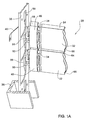
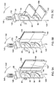
- Fig. 1A is an isometric view illustrating a portion of a vertical shutter with a tilting/locking mechanism, in accordance with the present invention, in a so-called closed position;
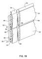
- Fig. 1B is an isometric view of only a portion of the shutters of Fig. 1A;
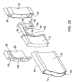
- Fig. 2A is an exploded isometric view of an end portion of a slat used in a shutter in accordance with the present invention, and a tilting and locking mechanism according to the invention;
- Fig. 2B is a rear isometric view corresponding with Fig. 2A;
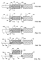
- Fig. 3A is a partially sectioned front elevation of a portion of a shutter in accordance with the present invention, the shutter in a closed position, and the tilting mechanism disengaged from the tilting actuator;
- Fig. 3B is a front elevation, partially sectioned, illustrating the tilting actuator in a position prior to engagement with the tilting mechanisms of the slats;
- Fig. 3C is a front elevation corresponding with the position illustrated in Fig. 1A, with the tilting actuator engaged with the tilting mechanisms of the slats;
- Fig. 3D is a front elevation of the shutter in an open position;
- Fig. 3E is an isometric view of a shutter in an open position;
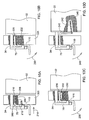
- Figs 4A-4C are partly sectioned top elevations corresponding with the positions of Figs. 3A-3D, respectively;
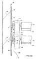
- Figs. 5A-5C are isometric views corresponding with the positions of Figs. 4A-4C, respectively;
- Figs. 6 and 7 are sections through a tilting and locking assembly in accordance with the present invention, illustrating the locking assembly in various states, as follows:
- Fig. 6A illustrates the locking assembly in a closed position, at rest;
- Fig. 6B illustrates the locking mechanism upon attempt to force a slat open, thereby shifting the locking mechanism to a locked position;
- Figs. 7A-7C illustrate consecutive steps of unlocking of the locking mechanism upon tilting of a slat using the tilting mechanism in accordance with the present invention;
- Figs. 8A and 8B illustrate a first embodiment of a tilting member in its respective locked and unlocked position;
- Figs. 9A and 9B illustrate a second embodiment of a tilting mechanism in its respective locked and unlocked position; and
- Figs. 10A-10H illustrate different embodiments for biasing a tilting member into a locked position.
-
- Fig 1 illustrates a portion of an adjustable shutter in accordance with the present invention generally designated 30. The shutter may be a vertical shutter i.e. of the type fitted at openings such as windows and doors, or it may be horizontal or inclined e.g. of the type installed in sun/light windows, etc. The shutter is illustrated with its
slats 32 at their so-called closed position, i.e. coplanar arranged in a manner in which their adjoining longitudinal edges overlap, as known per se.Slats 32 are pivotable about itspivot axis 34, which in the present example is horizontal. - The
shutter 30 is a slidable shutter which is rollable so as to allow complete access through the opening at which it is fitted, wherein side edges of theslats 32 are slidingly received within a concealingsupport rail 36 fixed within the opening. Thesupport rail 36 also supports a tiltingactuator 38 by means offlexible steel straps 40 and it also prevents tempering/picking of the tilting mechanism. Eachslat 32 is fitted at its respective end with a guidingmember 46 accommodating a tiltingmember 50 laterally projecting and serving also as part of the locking mechanism, partially received within the guidingmember 46, as will become apparent hereinafter. - Tilting
actuator 38 is in the form of a rigid strap of material (metal, plastic, etc) vertically extending and attached to thesupport rail 36 byflexible strips 40, thereby rendering the support rail to be displaceable both in its axial direction (vertical in the present case) and in a direction parallel to thepivot axis 34 of theslats 32.Strips 40 are typically made of steel straps though other arrangements are possible too, for supporting theactuator 38 in a displaceable manner, as mentioned above. The combined displacement of the tiltingactuator 38 is obtained, for example, by an electric motor fitted with a suitable cam (schematically illustrated in Figs. 5A-5C) or by means of a manual actuator or lever (not shown). - The tilting
actuator 38 is formed with a plurality of shapedapertures 56 which in fact serve as a cam engageable by tiltingmembers 50 which correspondingly serve as followers. The shape and dimensions ofapertures 56 dictate the tilting regime of the slats between an open position and a closed position, as will become apparent hereinafter. - Each guiding
link 46 is formed with anupper hook 58 pivotally engaged within a correspondinglower hook 60 of an adjoining guidingmember 46 as can best be seen in Fig. 1B. It is further noticed that in the closed position the slats interlock with one another wherein anupper edge 64 of one slat is received in an overlapping manner within a correspondingreceptacle 66 at a bottom edge of an adjacent slat. - Further attention is now directed to Figs. 2A and 2B illustrating a particular embodiment of a tilting and locking mechanism in accordance with the present invention. Guiding
member 46 accommodatespivot axle 34 fitted at one end with astump 72 adapted for snugly fitting withinaperture 74 ofslat 32. At an opposed end of thepivot axle 34 there is formed alever arm 78 formed adjacent afree end thereof 80 with alatch 84 for engaging with tiltingmember 50 and aslanted biasing portion 88 for clamping the tiltingmember 50 as will become apparent hereinafter. - Tilting
member 50 is pivotally retained within guidingmember 46 byblock member 90 formed with acorresponding recess 92 receiving anaxial portion 96 of the tiltingmember 50 and being essentially parallel with thefree portion 50 engagable with the tiltingactuator 38 as seen in Fig. 1A. Anintermediate portion 98 extends between theaxle portion 96 and the tiltingportion 50. Parallel tointermediate portion 98 there is a biasingarm portion 102 which at the assembled position bears against a biasingelastic portion 106, integral withblock member 90, so as to bias theintermediate portion 98 into engagement with a lockinglatch 110 formed at an opposite side thereof.Pivot axle 34 is received within a correspondingrecess 93 formed inblock 90, parallel to recess 92. - The locking mechanism fitted in the shutter illustrated in connection with the present embodiment may be omitted without interfering with the tilting function of the tilting mechanism. The purpose of the locking mechanism is to prevent tilting of the shutters by tampering with the shutters. Figs. 3 to 5 are directed to illustrating how slats fitted within a shutter in accordance with the present invention are tilted between closed and open positions whilst reference to the locking mechanism will be made in connection with the other Figures.
- With further reference also to Fig. 3A, the shutter is illustrated in a closed position wherein the
lateral engaging portion 51 of tiltingmember 50 extends not opposite anaperture 56 of the tiltingactuator 38. This position does not enable engagement of the engagingportion 51 of follower-type tilting members 50 within the cam-type apertures 56 whereby, engagement is facilitated only upon displacement of the slats and their associated tilting mechanism vertically, in direction ofarrow 122 or by displacing the tiltingactuator 38 in a combined motion represented byarrow 126, consisting of displacement along an axial direction thereof (essentially vertical) as well as displacement in an axis parallel to the pivot axis 34 (essentially horizontal). - Fig. 3B illustrates the shutter in a position after displacing the slats vertically downwards in the direction of
arrow 122, wherebylateral portion 51 of tiltingmember 50 extends opposite anopening 56 of the tiltingactuator 38, in a position suitable for engagement therewith. In Fig. 3C the tiltingactuator 38 is shown after further displacement ofarrow 126 whereby engagingportion 51 of tiltingmembers 50 are engaged withinopenings 56, theslats 32 still at their closed, untitled position. - Figs. 3D and 3E illustrate the shutter with
slats 32 in their tilted, namely open position, wherein the tiltingactuator 38 is further displaced along direction ofarrow 126 further departing from wall portion 36 (Fig. 3D), wherein theengaging arm portion 51 of tiltingmember 50 has reached practically the lowermost end ofaperture 56 formed in the tiltingactuator 38. It is appreciated, as already mentioned above, that the pattern ofaperture 56 dictates the regime by which theslats 36 tilt, namely the tilting rate is dependent from pattern (length and steepness-i.e. the gradient of the opening) of thecam opening 56. - As best apparent in Fig. 3E, the
intermediate portion 98 of the tiltingmember 50 is received betweenlatch 84 and biasingportion 88, thus ensuring that the tiltingmember 50 remains engaged withlever arm 78 which constitutes the rigid connection, viapivot axle 34 andstump 72 to tilting ofslat 32. - Figs. 4A-4C are top elevations illustrating the shutter assembly in three positions corresponding with Figs. 3A-3D respectively, wherein tilting
actuator 38 is fixed to avertical frame 133 formed withsupport rails member 46 upon its vertical displacement during rolling of the shutter, and which together withextension portion 138 conceal the tilting and locking mechanism so as to prevent tampering therewith. It is to be appreciated that a variety of such frames are possible, depending on particular configuration of the opening etc. - The position of Fig. 4A corresponds to either of the positions illustrated in Figs. 3A and 3B, wherein the tilting
actuator 38 is at its retracted position namely, wherein engagingportion 51 of tiltingmember 50 is disengaged from theapertures 56 formed in the tiltingactuator 38. - Fig. 4B corresponds with the position of Fig. 3C, wherein the engaging
portion 51 of tiltingmember 50 is engaged within a correspondingaperture 56 of the tiltingactuator 38, thus slats 32 are still in their closed, un-tilted position. - Fig. 4C corresponds with the position illustrated in Figs. 3D and 3E, wherein the tilting
actuator 38 has completed its displacement and has vertically displaced to its extreme position, wherebyshutter 32 has tilted into its open position. - Figs. 5A to 5C illustrate an embodiment exemplifying how the tilting
actuator 38 may be displaced during a tilting sequence. As already explained above, the tiltingactuator 38 is fixed to a wall portion (not shown) by means ofstraps 40 made for example of a steel-spring leaf which constantly biases the tiltingactuator 38 in an axially upward direction and in a horizontal direction away from the slats, as represented byarrow 142. Aneccentric cam actuator 146 is fitted on a shaft of anelectric motor 149 whereby rotation of theactuator 146 in the direction ofarrow 152 entails displacement of the tiltingactuator 38 in direction ofarrow 128, as explained hereinabove, entailing tilting of theslats 32. However, it is appreciated that manipulating the tiltingactuator 38 may be obtained by other arrangement as well, such as, for example, a manual lever, etc. - As discussed hereinbefore (Figs. 2A and 2B), the
intermediate portion 98 of the tiltingmember 50 is at all times engaged withlever arm 78, though having sufficient clearance. Furthermore, as noticed from the previous Figures, at the un-tilted, closed position of the slats,portion 102 of the tiltingmember 50 remains engaged and biased by a biasingmember 106 of theblock member 90 fitted within guidingmember 46. Thus, when theslats 32 are un-tilted, the biasing effect onportion 102 of the tiltingmember 50 entailsintermediate portion 98 to bear against lockinglatch 110, as illustrated in Fig. 6A. When, however, an attempt is made to tiltslat 32 by applying thereto a force in the direction ofarrow 164 in Fig. 6B, a corresponding tilting force is applied viapivot axle 34 to leverarm 78, resulting in clamping ofintermediate portion 98 between lockinglatch 110 and biasingmember 88 oflever arm 78, preventing tilting of theslat 32. In fact, force applied in the direction ofarrow 164 increases the clamping effect ofintermediate portion 98 between the lockinglatch 110 and the biasingportion 88. - Preventing tilting of the
slats 32 in a counter direction, namely inwards, is prohibited owing to the overlapping engagement of the slats, in accordance with one embodiment, as illustrated, for example, in Figs. 5A and 5B, wherein a bottom edge of the slats is formed at an outer face thereof with aprojection 182 which overlappingly bears against a correspondingvertical projection 184 formed at a top edge of theslat 32, thus preventing tilting of the slats inwardly (i.e. in a direction counter to that illustrated in Fig. 5C, i.e. counter clockwise ). - Turning now to Figs. 7A-7C, the locking mechanism is illustrated in the position (wherein for sake of clarity the actuator removed) in which the tilting mechanism is actuated by applying thereto lateral force represented by
arrow 188 imparted thereto by the tilting actuator whereupon theintermediate portion 98 does not engage with the lockinglatch 110 and whereby it is free to pivot into the position of Fig. 7C, together with the interlinkedlever arm 78, entailing corresponding tilt of therespective slat 32. - It is thus necessary to impart the tilting
member 50, and more specifically theintermediate portion 98 thereof, with an axial degree of freedom, between a position in which it is engagingly arrested by lockinglatch 110, and a disengaged position whereby it is free to pivot about theaxial portion 96 entailing pivotal displacement ofpivot axle 34 and the associated slats. - Figs. 8A and 8B illustrate one embodiment in which the
block member 90a is formed with arecess 92a which is essentially parallel withrecess 93 accommodating the pivot axle (not shown), wherebyaxial portion 96 is displaceable withinrecess 92a only in an axial direction alongarrows intermediate portion 98 is arrested by a lockinglatch 110 and an unlocked position in whichintermediate portion 98 is disengaged from lockinglatch 110, against the biasing effect of biasingmember 106, as illustrated in Fig. 8B. - A different embodiment is illustrated in Figs. 9A and 9B, wherein the
block member 90b is formed with arecess 92b slantingly extending with respect to recess 93 accommodating the pivot axle 34 (not shown) whereupon the tiltingmember 50 is swingably displaceable alongarrows intermediate portion 98 is arrested by lockinglatch 110 and an unlocked position, against the biasing effect of biasingmember 106, wherebyintermediate portion 98 is disengaged from lockinglatch 110. - Figs. 10A-10H illustrate different biasing arrangements for biasing a tilting member into engagement with a locking
latch 110 of a block member. In all the illustrated embodiments the respective block member pivotally accommodates a pivot axle 334 connectinglever arm 78 withslat 32 as disclosed in connection with all the previous embodiments. In the embodiment of Fig.10A block member 200 accommodates anaxle portion 202 received within abore 204 and biased by means of coiledspring 206 bearing at one end against ashoulder 208 of theblock member 200 and at an opposed end against anannular rim 210 of theaxle portion 202, biasing the tilting member, namely theintermediate portion 212 in the direction ofarrow 214. - In the embodiment of Fig. 10B tilting member is biased in the direction of
arrow 220 by means of acompression spring 222 fitted within a bore formed inblock member 224 applying force on the axle portion of the tilting member. - The embodiment of Fig. 10C is similar to the embodiment of Fig. 10B, whereby a leaf-
type spring 230 received within arecess 232 applies biasing force onaxial portion 236 of the tilting member, thus biasing it in the direction of 238. - In the embodiment of Fig. 10D a different concept is illustrated wherein
arm portion 240 of the tilting member is articulated to one end of acoiled spring 242, another end thereof fixed within thestump portion 246 within theslat 32, thus giving rise to a biasing force in the direction ofarrow 248. - The arrangement illustrated in Fig. 10E comprises a leaf-
type spring 250 having afirst arm 252 secured to blockmember 254 and asecond arm 256 secured toaxle portion 258 of the tilting member, whereby the leaf-spring is a compression spring in which arm 256 is biased towardsarm 252, giving rise to biasing theintermediate arm 260 in the direction ofarrow 262. A similar arrangement is disclosed in Fig. 10F, wherein abiasing arm 270 made of a resilient material is integral with theblock member 272 and engaged with an end ofaxle portion 276, giving rise to a tilting biasing force in the direction ofarrow 280. - Fig. 10G discloses a
block member 284 formed with anintegral spring portion 286 bearing againstaxle portion 288 and biasing it in the direction ofarrow 290. The biasing arrangement of Fig. 10H comprises a leaf-type spring 294 riveted at 296 to leverarm 78, with an opposed end thereof 298 bearing against theintermediate portion 300, thus giving rise to a biasing force in the direction ofarrow 306.
Claims (43)
- An adjustable shutter comprising a plurality of slats parallelly extending at adjoining relationship, each slat comprising a pivot axis parallel to a longitudinal direction thereof; each slat associated with a tilting mechanism at least at one end thereof, said tilting mechanism engageable with a corresponding tilting actuator displaceable in an axial direction normal to the pivot axis; the slats being linked to one another at adjoining edges of neighboring tilting mechanisms; each tilting mechanism comprises a guiding member and a tilting member whereby displacing the tilting actuator entails tilting of the slats about said pivot axis between open and closed positions, and whereby the slats are displaceable in the axial direction.
- An adjustable shutter according to claim 1, wherein the guiding members of the slats are displaceable along support rails fitted at both ends thereof.
- An adjustable shutter according to claim 1, wherein the tilting actuator disengages from the tilting member to enable displacement of the slats along said support rails.
- An adjustable shutter according to claim 1, wherein the tilting member is a pin extending parallel to said pivot axis.
- An adjustable shutter according to claim 2, wherein the tilting actuator is a cam-type member and the tilting member is a follower-type member.
- An adjustable shutter according to claim 2, wherein the tilting actuator is a strap of rigid material formed with plurality of openings each defining a cam path engageable with a corresponding tilting member, the tilting actuator being displaceable in the axial direction so as to effect tilting of the slats, and in a direction parallel to the pivot axis so as to effect respective engagement and disengagement thereof with the respective tilting members of the slats.
- An adjustable shutter according to claim 1, wherein the slats are rollable over a pickup axis parallel to the pivot axis of the slats.
- An adjustable shutter according to claim 1, wherein each slat has a top edge and a bottom edge, where a bottom edge of one slat overlaps a top edge of a an adjacent slat.
- An adjustable shutter according to claim 8, wherein the top edge of one slat is receivable by a bottom edge of a an adjacent slat
- An adjustable shutter according to claim 1, further comprising a locking mechanism associated with the tilting mechanism, said locking mechanism facilitating tilting of the respective slat only via the tilting mechanism and preventing tilting of the slats when by tilting the slats.
- An adjustable shutter according to claim 3, wherein each slat may be tilted any location along the axial direction.
- An adjustable shutter according to claim 1, wherein the slats are linked to one another via interlining members linked at adjoining edges of guiding members of neighboring tilting mechanisms.
- An adjustable shutter according to claim 10, wherein the tilting member is engageable with the actuating member for imparting thereto pivotal displacement to facilitate tilting of a slat, and being arrested by a locking latch fixed to the guiding member when the slat is in a tilted position.
- An adjustable shutter according to claim 13, wherein when an attempt is made to tilt a slat when at its closed position, the tilting member is arrested by the locking mechanism, whereby the slat is retained locked at the closed position.
- An adjustable shutter according to claim 1, wherein the tilting mechanism comprises a pivot axle fixedly attached to a respective slat and pivotally extending through an associated guiding member, and a laterally extending tilting member engageable with the tilting actuator and coupled with a lever arm fixed onto said pivot axle, for pivotal displacement therewith.
- An adjustable shutter according to claim 15, wherein the lever arm comprises a biasing portion for displacing the tilting member towards a locking latch fixed to the guiding member, whereby when a slat is in the closed position and an attempt is made to tilt the slat, the biasing portion displaces the tilting member into arresting engagement with the locking latch, thus preventing tilting of the slat.
- An adjustable shutter according to claim 15, wherein at the closed position of a slat, the tilting member is biased towards the locking latch.
- An adjustable shutter according to claim 15, wherein the guiding member is fitted with a biasing member for biasing the tilting member towards the locking latch.
- An adjustable shutter according to claim 15, wherein the tilting member comprises an axle portion pivotally articulated to the guiding member, and intermediate portion interacting with the lever arm, and a free arm, parallel with the axle portion and being engageable with the tilting actuator.
- An adjustable shutter according to claim 19, wherein the axle portion of the tilting member is spring biased so as to bias the intermediate portion towards the locking latch.
- An adjustable shutter according to claim 16, wherein engagement of the tilting member with the tilting actuator entails disengagement of the tilting member from the locking latch.
- An adjustable shutter according to claim 19, wherein the axle portion of the tilting member is axially displaceable with respect to the guiding member, between a position in which the intermediate portion is engaged from the locking latch and a position in which the intermediate portion is disengaged from the locking latch.
- An adjustable shutter according to claim 19, wherein the axle portion of the tilting member is pivoted to the guiding member parallelly offset with respect to the pivot axle.
- An adjustable shutter according to Claim 19, wherein the tilting member further comprises a stem portion fixedly extending from the axle portion and fitted for engagement with a slat.
- A locking mechanism for an adjustable shutter comprising a plurality of slats parallelly extending at adjoining relationship and supported to a frame by a guiding member at each respective end thereof, each slat comprising a pivot axis parallel to a longitudinal direction thereof; each slat associated with a tilting mechanism at least at one end thereof engageable with an tilt actuator; said locking mechanism facilitating tilting of the respective slat only via the tilting mechanism and preventing tilting of the slats when by tilting the slats.
- A locking mechanism for an adjustable shutter according to claim 25, wherein the tilting mechanism comprises a tilting member arrestable by a locking latch fixed to the guiding member when a slat is in a tilted position.
- A locking mechanism according to claim 26, wherein when an attempt is made to tilt a slat when at its closed position, the tilting member is arrested by the locking mechanism, whereby the slat is retained locked at the closed position.
- A locking mechanism according to claim 25, wherein a lever arm of the tilting mechanism comprises a biasing portion for displacing the tilting member towards a locking latch fixed to the guiding member, whereby when a slat is in the closed position and an attempt is made to tilt the slat, the biasing portion displaces the tilting member into arresting engagement with the locking latch, thus preventing tilting of the slat
- A locking mechanism according to claim 25, wherein at the closed position of a slat, the tilting member is biased towards the locking latch.
- A locking mechanism according to claim 25, wherein the guiding member is fitted A locking mechanism according to claim 25, wherein
- A locking mechanism according to claim 25, wherein the slats are rollable over a pickup axis parallel to the pivot axis of the slats.
- A locking mechanism according to claim 25, wherein an axle portion of the tilting member pivotally articulated to the guiding member and is spring biased so as to bias an intermediate portion of the tilting member towards the locking latch.
- A locking mechanism according to claim 25, wherein engagement of the tilting member with the tilting actuator entails disengagement of the tilting member from the locking latch.
- A locking mechanism according to claim 25, wherein respective ends of the slats are received within support rails, whereby the locking mechanism and the tilting mechanism are concealed.
- A tilting mechanism for an adjustable shutter comprising a plurality of slats parallelly extending at adjoining relationship, each slat comprising a pivot axis parallel to a longitudinal direction thereof; the tilting mechanism comprising a tilting member engageable with a tilting actuator displaceable in an axial direction normal to the pivot axis; whereby displacing the tilting actuator entails tilting of the slats about said pivot axis between open and closed positions, and whereby the slats are displaceable in the axial direction.
- A tilting mechanism according to claim 35, further comprising a guiding member associated with each slat and being displaceable along a guide rail supporting the shutter at both ends thereof.
- A tilting mechanism according to claim 35, wherein the tilting actuator disengages from the tilting member to enable displacement of the slats along said support rails.
- A tilting mechanism according to claim 35, wherein the tilting member is a pin extending parallel to said pivot axis.
- A tilting mechanism according to claim 35, wherein the tilting actuator is a cam-type member and the tilting member is a follower type member.
- A tilting mechanism according to claim 35, wherein the tilting actuator is a strap of rigid material formed with plurality of openings, each defining a cam path engageable with a corresponding tilting member, the tilting actuator being displaceable in the axial direction so as to effect tilting of the slats, and in a direction parallel to the pivot axis so as to effect respective engagement and disengagement thereof with the respective tilting members of the slats.
- A tilting mechanism according to claim 35, wherein at a state at which the tilting members are disengaged from the tilting actuator, the shutter is rollable along the support rails.
- A tilting mechanism according to claim 36, wherein the tilting actuator is received within the support rails in a concealed manner.
- A tilting mechanism according to Claim 35, wherein the tilting member is fitted with a stem portion fitted for fixedly attaching to an end of a respective slat.
Applications Claiming Priority (2)
| Application Number | Priority Date | Filing Date | Title |
|---|---|---|---|
| IL14484101A IL144841A0 (en) | 2001-08-09 | 2001-08-09 | Louverable shutter |
| IL14484101 | 2001-08-09 |
Publications (2)
| Publication Number | Publication Date |
|---|---|
| EP1286016A2 true EP1286016A2 (en) | 2003-02-26 |
| EP1286016A3 EP1286016A3 (en) | 2004-01-02 |
Family
ID=11075682
Family Applications (1)
| Application Number | Title | Priority Date | Filing Date |
|---|---|---|---|
| EP02017472A Withdrawn EP1286016A3 (en) | 2001-08-09 | 2002-08-05 | Louverable shutter |
Country Status (2)
| Country | Link |
|---|---|
| EP (1) | EP1286016A3 (en) |
| IL (1) | IL144841A0 (en) |
Cited By (7)
| Publication number | Priority date | Publication date | Assignee | Title |
|---|---|---|---|---|
| WO2007017214A1 (en) * | 2005-08-10 | 2007-02-15 | Roma Rolladensysteme Gmbh | Jalousie-type roller blind |
| WO2007017218A2 (en) * | 2005-08-10 | 2007-02-15 | Roma Rolladensysteme Gmbh | Roller blind for a skylight |
| EP1837480A2 (en) * | 2006-03-23 | 2007-09-26 | Attilio Bianchetti | Roller shutters with swivelling slats |
| WO2009143842A1 (en) * | 2008-05-28 | 2009-12-03 | Vkr Holding A/S | Roller shutter with tiltable slats |
| EP2148041A1 (en) * | 2008-07-24 | 2010-01-27 | Bubendorff | Apron for closing and/or concealing system with guidable slats and roller shutter comprising such an apron. |
| FR2958318A1 (en) * | 2010-04-01 | 2011-10-07 | Lionel Planquette | Roller-shutter for closing opening in dwelling, has activating element cooperating with stair carriage integrated to slides and movable along direction perpendicular to slides to move plate between maximum and intermediate closing positions |
| WO2012080386A1 (en) * | 2010-12-15 | 2012-06-21 | Lionel Planquette | Mechanism for rotating the slats of a roller shutter |
Citations (8)
| Publication number | Priority date | Publication date | Assignee | Title |
|---|---|---|---|---|
| US3842891A (en) | 1973-08-27 | 1974-10-22 | S Kinnroth | Shutter-blind device |
| US4519434A (en) | 1982-11-19 | 1985-05-28 | Security Shutter Corporation | Winding mechanism for rollable shutter curtain |
| US4715421A (en) | 1983-10-25 | 1987-12-29 | Erber Guenther | Roller shutter with jalousie-type louvers |
| US5070925A (en) | 1990-06-08 | 1991-12-10 | Prime Marketing Group, Inc. | Security shutter system |
| US5188161A (en) | 1989-02-07 | 1993-02-23 | Gunther Erber | Louverable rolling shutter |
| US5469905A (en) | 1993-09-07 | 1995-11-28 | Fold-A-Shield | Security and hurricane shutter |
| US5566738A (en) | 1994-05-15 | 1996-10-22 | Yadidya; Hagay | Louvered movable window shutter |
| US5575322A (en) | 1995-09-15 | 1996-11-19 | Miller; James V. | Rolling protective shutters |
Family Cites Families (4)
| Publication number | Priority date | Publication date | Assignee | Title |
|---|---|---|---|---|
| DE3501689A1 (en) * | 1985-01-19 | 1986-07-24 | Helmut Ing.(grad.) 7847 Badenweiler Rathmann | SHUTTER BLINDS |
| ATA206486A (en) * | 1986-07-31 | 1991-06-15 | Franz Gertl | SHUTTER |
| AT403829B (en) * | 1996-05-02 | 1998-05-25 | Famulus Elektrogeraete Gmbh | Venetian-blind-type roller shutter |
| WO1998031910A2 (en) * | 1997-01-20 | 1998-07-23 | Uwe Steinleitner | Louver-style rolling shutter |
-
2001
- 2001-08-09 IL IL14484101A patent/IL144841A0/en unknown
-
2002
- 2002-08-05 EP EP02017472A patent/EP1286016A3/en not_active Withdrawn
Patent Citations (9)
| Publication number | Priority date | Publication date | Assignee | Title |
|---|---|---|---|---|
| US3842891A (en) | 1973-08-27 | 1974-10-22 | S Kinnroth | Shutter-blind device |
| US4519434A (en) | 1982-11-19 | 1985-05-28 | Security Shutter Corporation | Winding mechanism for rollable shutter curtain |
| US4715421A (en) | 1983-10-25 | 1987-12-29 | Erber Guenther | Roller shutter with jalousie-type louvers |
| US5188161A (en) | 1989-02-07 | 1993-02-23 | Gunther Erber | Louverable rolling shutter |
| US5070925A (en) | 1990-06-08 | 1991-12-10 | Prime Marketing Group, Inc. | Security shutter system |
| US5469905A (en) | 1993-09-07 | 1995-11-28 | Fold-A-Shield | Security and hurricane shutter |
| US5566738A (en) | 1994-05-15 | 1996-10-22 | Yadidya; Hagay | Louvered movable window shutter |
| IL109652A (en) | 1994-05-15 | 1997-06-10 | Yedidia Hagai | Louvered movable window shutter |
| US5575322A (en) | 1995-09-15 | 1996-11-19 | Miller; James V. | Rolling protective shutters |
Cited By (9)
| Publication number | Priority date | Publication date | Assignee | Title |
|---|---|---|---|---|
| WO2007017214A1 (en) * | 2005-08-10 | 2007-02-15 | Roma Rolladensysteme Gmbh | Jalousie-type roller blind |
| WO2007017218A2 (en) * | 2005-08-10 | 2007-02-15 | Roma Rolladensysteme Gmbh | Roller blind for a skylight |
| WO2007017218A3 (en) * | 2005-08-10 | 2007-08-09 | Roma Rolladensysteme Gmbh | Roller blind for a skylight |
| EP1837480A2 (en) * | 2006-03-23 | 2007-09-26 | Attilio Bianchetti | Roller shutters with swivelling slats |
| EP1837480A3 (en) * | 2006-03-23 | 2011-01-05 | Attilio Bianchetti | Roller shutters with swivelling slats |
| WO2009143842A1 (en) * | 2008-05-28 | 2009-12-03 | Vkr Holding A/S | Roller shutter with tiltable slats |
| EP2148041A1 (en) * | 2008-07-24 | 2010-01-27 | Bubendorff | Apron for closing and/or concealing system with guidable slats and roller shutter comprising such an apron. |
| FR2958318A1 (en) * | 2010-04-01 | 2011-10-07 | Lionel Planquette | Roller-shutter for closing opening in dwelling, has activating element cooperating with stair carriage integrated to slides and movable along direction perpendicular to slides to move plate between maximum and intermediate closing positions |
| WO2012080386A1 (en) * | 2010-12-15 | 2012-06-21 | Lionel Planquette | Mechanism for rotating the slats of a roller shutter |
Also Published As
| Publication number | Publication date |
|---|---|
| EP1286016A3 (en) | 2004-01-02 |
| IL144841A0 (en) | 2002-06-30 |
Similar Documents
| Publication | Publication Date | Title |
|---|---|---|
| EP1612354A2 (en) | Upper articulation assembly for turn and tilt window or door. | |
| EP1370742B1 (en) | Window or door structure | |
| AU639631B2 (en) | A window operator and hinge structure | |
| CN101532365B (en) | Metalwork of a window and elements thereof | |
| EP1056921B1 (en) | Roll-up shutter | |
| US5836111A (en) | Opening-closing device for windows | |
| US20070289100A1 (en) | Casement Window Hinge | |
| CA2130052A1 (en) | Locking system for a double hung window | |
| EP1286016A2 (en) | Louverable shutter | |
| EP0296420A2 (en) | Window shutter | |
| KR101989754B1 (en) | sliding system window | |
| US7422519B2 (en) | Chimney damper | |
| DE10261157B4 (en) | Automatic folding door system | |
| DE8816626U1 (en) | Roof window shutters | |
| RU2230866C2 (en) | Fixture member confining the opening | |
| AT412225B (en) | LOCKING DEVICE FOR WINDOWS AND DOORS | |
| US11866966B2 (en) | Device for constraining the opening of doors or windows | |
| US20240209669A1 (en) | Hinge for a roof window and roof window with a set of hinges | |
| US5855236A (en) | Blind assembly | |
| DE19811373A1 (en) | Window with surround frame and operated hinge assembly | |
| US20240209665A1 (en) | Hinge for a roof window and roof window with a set of hinges | |
| KR200360278Y1 (en) | Stay Bar for Turning Type Window | |
| AU2003204589B2 (en) | Roll-up shutter | |
| DE8901614U1 (en) | Roller shutters for a roof window | |
| EP4330499A1 (en) | Hinge for a roof window and roof window with a set of hinges |
Legal Events
| Date | Code | Title | Description |
|---|---|---|---|
| PUAI | Public reference made under article 153(3) epc to a published international application that has entered the european phase |
Free format text: ORIGINAL CODE: 0009012 |
|
| AK | Designated contracting states |
Kind code of ref document: A2 Designated state(s): AT BE BG CH CY CZ DE DK EE ES FI FR GB GR IE IT LI LU MC NL PT SE SK TR Designated state(s): AT BE BG CH CY CZ DE DK EE ES FI FR GB GR IE IT LI LU MC NL PT SE SK TR |
|
| AX | Request for extension of the european patent |
Extension state: AL LT LV MK RO SI |
|
| PUAL | Search report despatched |
Free format text: ORIGINAL CODE: 0009013 |
|
| AK | Designated contracting states |
Kind code of ref document: A3 Designated state(s): AT BE BG CH CY CZ DE DK EE ES FI FR GB GR IE IT LI LU MC NL PT SE SK TR |
|
| AX | Request for extension of the european patent |
Extension state: AL LT LV MK RO SI |
|
| AKX | Designation fees paid | ||
| REG | Reference to a national code |
Ref country code: DE Ref legal event code: 8566 |
|
| STAA | Information on the status of an ep patent application or granted ep patent |
Free format text: STATUS: THE APPLICATION IS DEEMED TO BE WITHDRAWN |
|
| 18D | Application deemed to be withdrawn |
Effective date: 20040703 |