EP1285687A1 - Vorrichtung zum Absorbieren von in einen Abgasstrom enthaltenen Verbindungen - Google Patents
Vorrichtung zum Absorbieren von in einen Abgasstrom enthaltenen Verbindungen Download PDFInfo
- Publication number
- EP1285687A1 EP1285687A1 EP02292067A EP02292067A EP1285687A1 EP 1285687 A1 EP1285687 A1 EP 1285687A1 EP 02292067 A EP02292067 A EP 02292067A EP 02292067 A EP02292067 A EP 02292067A EP 1285687 A1 EP1285687 A1 EP 1285687A1
- Authority
- EP
- European Patent Office
- Prior art keywords
- generating
- flow
- transfer channel
- solvent
- downstream
- Prior art date
- Legal status (The legal status is an assumption and is not a legal conclusion. Google has not performed a legal analysis and makes no representation as to the accuracy of the status listed.)
- Withdrawn
Links
Images


Classifications
-
- B—PERFORMING OPERATIONS; TRANSPORTING
- B01—PHYSICAL OR CHEMICAL PROCESSES OR APPARATUS IN GENERAL
- B01D—SEPARATION
- B01D53/00—Separation of gases or vapours; Recovering vapours of volatile solvents from gases; Chemical or biological purification of waste gases, e.g. engine exhaust gases, smoke, fumes, flue gases, aerosols
- B01D53/14—Separation of gases or vapours; Recovering vapours of volatile solvents from gases; Chemical or biological purification of waste gases, e.g. engine exhaust gases, smoke, fumes, flue gases, aerosols by absorption
- B01D53/18—Absorbing units; Liquid distributors therefor
- B01D53/185—Liquid distributors
Definitions
- the invention relates to the separation of volatile compounds present in a gas, especially when the concentration of such compounds is low.
- the invention thus relates in particular to recovery by concentration of specific gas molecules initially diluted in an air flow.
- the main areas of application are on the one hand recovery molecules of interest (association of the process with purification by membranes for example) and on the other hand the degradation of pollutants (combination of the process and a final biological or incineration treatment for example).
- the device comprising a transfer channel for this fluid gas, provided with means for spraying a solvent within this channel transfer device, characterized in that it further comprises means to generate, in the transfer channel, a flow rotating around a main direction of flow of this transfer channel.
- a recovery process is also proposed. of compounds present in a gaseous fluid, comprising the steps consisting in transferring this gaseous fluid into a transfer channel and in spraying a solvent into this channel, characterized in that it further comprises the step of creating a rotating flow in the channel around a main direction of flow of the channel.
- the objective sought in the embodiment which will be described, is to concentrate in a low gas flow the molecules of interest or the pollutants contained in high flow rates of industrial gaseous effluents.
- the absorption is carried out by an "aero-ejector" or spray transfer channel 110 shown in FIGS. 3 and 4, fed by a flow of polluted gas Q G and by two flows of liquid solvent Q L1 and Q L2 .
- a first injection of solvent is carried out by a spraying device 111 located at the inlet of the transfer channel 110.
- the main two-phase mixing is carried out in the current part of the channel 110 which includes several abrupt enlargements 112 whose role is to generate turbulences of significant intensities.
- the gas and liquid phases initially separated, undergo breaking resulting in drops of liquid embedded in a very gas phase discontinuous: the interfacial gas-liquid contact area becomes large, as well as the transfer coefficient.
- C ⁇ is the compound to be recovered, in particular gaseous, which one wishes to absorb
- the injected liquid must not contain it, or possibly at very low concentration (much lower than the saturation concentration).
- a fluid flow Q L2 here a liquid flow and even more precisely a flow of solvent, is injected through a small tangential orifice 116, and causes a rotating flow (high tangential speed) in the transfer channel by effect of centrifugal forces, this fluid flows in movement rotating along walls encircling the main direction of channel 110.
- the relative pressure in a part of the core of this rotating movement typically becomes negative: this creates a suction process at the inlet of the transfer channel (aero-ejector), and therefore a necessary supply pressure P G of the polluted gas at the entry of the transfer channel which is particularly weak, or even which may be atmospheric pressure.
- This pressure drop particularly in the vicinity of the injection of solvent Q L1 , increases the transfer rate in the current part of the channel 110, which can thus go up to 100%.
- This rotating flow also gives rise to constraints of shear at the level of the rotating flux which causes an intimate mixture of gas and liquid phases, resulting in a liquid flow containing fine gas bubbles. This area is therefore the seat of a gas-liquid transfer important.
- the rotating flow therefore makes it possible on the one hand to reduce the pressure compression required for the effluent, thereby increasing the transfer of the gases into the current part of the aero-ejector, and give birth to a additional transfer area, high efficiency.
- the means for generating a rotating flow are positioned at the inlet of the aero-ejector 110 in a tank 120 which will be described below.
- This rotating flow means include besides two concentric walls 117 and 118 and surrounding a main axis of the effluent flow.
- the injector 116 of rotating fluid being placed between these two walls, the rotating flow is first guided in rotation between these two walls 117 and 118.
- the space between the two walls is open towards the downstream direction of the transfer channel, so that the rotating flow joins the main flow effluent through this open part, surrounding the main flow at this point effluent.
- the canal transfer (or aero-ejector) has, downstream of the walls 117 and 118, a wall 119 which widens in the downstream direction of the canal, and which therefore tends to then slow down the gas speed.
- the whole (Q L1 + Q L2 ) of the liquid flow is recovered in a reactor 120, formed by a solvent tank in which the aero-ejector 110 opens in the downward direction.
- This assembly consisting of the aero-ejector 110 and the reactor 120, forms the gas-liquid contactor 100 in which the process is carried out absorption.
- This set provides a complete transfer.
- the liquid present in the reactor 120 contains the compounds C ⁇ in the form of dissolved gas.
- the liquid phase contained in the reactor 120 is renewed continuously (flow rate Q L3 ).
- Liquid flows QL1 and QL2 can either come from recycling after separation of the compounds contained in the solvent of the reactor, either be created by internal recycling via a pump ( Figure 2).
- the charged solvent from reactor 120 is then treated in a desorber 200 shown in Figure 5.
- Desorption of dissolved gases consists in creating a new flow gas-liquid with dispersed gas bubbles from the gases dissolved in the liquid. For this, a negative relative pressure is caused in the desorber 200, here by the flow itself.
- a chamber 210 in the form of a tube of diameter D 1 , receives the flow rate Q L3 of liquid coming from the reactor 120 and containing the compounds C ⁇ in dissolved form.
- One or more tubes 220 of diameter D 2 smaller than D1 come from downstream of this chamber 210, and implanted in such a way that their upstream end 225 is located upstream from a solid bottom 215 which closes the chamber 210.
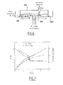
- the present device finally comprises a third element 300 (FIG. 6), called the separator.
- This third element 300 is to carry out the separation between the flow rates Q LS liquid and Q GS gas. Knowing that the gas is in the form of microbubbles, it is necessary to ensure a relatively long residence time of the mixture in this separator 300.
- the mixture diphasic is caused to flow on a cone 310 (or inclined plane) of diameter (or length L) such that, in a common area 320 of this cone, a low hydraulic speed and a small draft are obtained.
- the cone (or the slope) is fed by a mouth placed at the bottom of this cone, so that the mixture runs through the cone from the bottom, towards its edges higher. Under these conditions, the microbubbles reach the free surface S quickly, and at least before reaching the tip of the cone (or of the inclined plane).
- These constraints require a fairly cone angle important (or of the inclined plane) and a diameter D (or a length of the plane inclined) also quite large, to obtain a satisfactory yield.
- the gas thus separated is collected in an upper bell 330, covering the separation cone (or slope). This gas is evacuated for further treatment, either to recover the compounds C ⁇ if they can be recovered, or to degrade them if they are pollutants.
- the liquid is collected in a lower tank 340 and then recycled to the contactor 100.
- the liquid no longer contains compounds C ⁇ . It should be noted that if this liquid still contains a residual concentration of C ⁇ , the proper functioning of the process only requires that this concentration be much lower than the saturation concentration of the compound in the liquid.
- the separator 300 is located above contactor 100, which corresponds to a geometry slightly different from that described above, but obeying the same principles of separation of gas and liquid.
- the system proposed here makes it possible to achieve flow ratios of the order of 15 to 20 between liquid phase and phase gas.
- the various methodologies applicable to the treatment gases can be classified into two categories, namely those which result directly in a purified gas (these are biological processes and incineration), and those that concentrate pollutants in gas flows smaller (these are condensation, adsorption and absorption).
- a first advantage is the continuous operation of the process. then adsorption, due to the successive stages of retention and washing, minimum two adsorption columns are necessary and work sequentially.
- a second advantage is the volume of the contactor: the current geometry of the aero-ejector makes it possible to consider reducing the useful volume up to a value of the order of 0.001 m 3 / (m 3 / h) of treated gas. , while the current values are around 0.006.
- a third advantage is the flow of polluted gas Q GS which it is necessary to treat in the final stage (recovery or degradation).
- this flow is of the order of 1/10 th of the initial flow Q G.
- this flow rate Q GS should be of the order of 1/400 th of Q G.
- a first advantage is the flow of polluted gas Q GS treated: ratio of the order of 400.
- a second advantage is the energy required for combustion: this point is obviously linked to the previous point, but also possibly to the fact that the proposed process greatly increases the concentration of compounds to be eliminated. If these compounds have a sufficient energy level, this energy is released during combustion and can participate in self-combustion which reduces the energy consumption by incineration.
- the various elements are units with no moving parts (reliability), the only source of energy possibly desirable being a hydraulic pump, element perfectly known and mastered in all businesses.
Landscapes
- Chemical & Material Sciences (AREA)
- Engineering & Computer Science (AREA)
- Analytical Chemistry (AREA)
- General Chemical & Material Sciences (AREA)
- Oil, Petroleum & Natural Gas (AREA)
- Chemical Kinetics & Catalysis (AREA)
- Gas Separation By Absorption (AREA)
- Treating Waste Gases (AREA)
Applications Claiming Priority (2)
| Application Number | Priority Date | Filing Date | Title |
|---|---|---|---|
| FR0110948A FR2828817B1 (fr) | 2001-08-21 | 2001-08-21 | Dispositif d'absorption de compose dans un effluent gazeux, a rendement ameliore |
| FR0110948 | 2001-08-21 |
Publications (1)
| Publication Number | Publication Date |
|---|---|
| EP1285687A1 true EP1285687A1 (de) | 2003-02-26 |
Family
ID=8866625
Family Applications (1)
| Application Number | Title | Priority Date | Filing Date |
|---|---|---|---|
| EP02292067A Withdrawn EP1285687A1 (de) | 2001-08-21 | 2002-08-21 | Vorrichtung zum Absorbieren von in einen Abgasstrom enthaltenen Verbindungen |
Country Status (2)
| Country | Link |
|---|---|
| EP (1) | EP1285687A1 (de) |
| FR (1) | FR2828817B1 (de) |
Cited By (2)
| Publication number | Priority date | Publication date | Assignee | Title |
|---|---|---|---|---|
| CN110339695A (zh) * | 2019-07-24 | 2019-10-18 | 山东大学 | 一种船舶废气脱硝处理系统 |
| CN112546776A (zh) * | 2020-11-23 | 2021-03-26 | 珠海格力智能装备有限公司 | 一种空调系统管路件焊接废气治理装置及使用方法 |
Families Citing this family (1)
| Publication number | Priority date | Publication date | Assignee | Title |
|---|---|---|---|---|
| RU2644604C1 (ru) * | 2016-10-31 | 2018-02-13 | Марат Минасхатович Ризванов | Сопло для создания реактивной газовой и жидкостной струи для сместителей |
Citations (3)
| Publication number | Priority date | Publication date | Assignee | Title |
|---|---|---|---|---|
| GB769821A (en) * | 1954-06-05 | 1957-03-13 | Svenska Flaektfabriken Ab | Method and device for supplying, spraying and mixing a liquid in a gaseous medium flowing in a channel |
| SU865346A1 (ru) * | 1979-03-15 | 1981-09-23 | Предприятие П/Я В-8796 | Пылеуловитель |
| US5061408A (en) * | 1989-11-25 | 1991-10-29 | Bayer Aktiengesellschaft | Apparatus for mass transfer between a hot gas stream and a liquid |
-
2001
- 2001-08-21 FR FR0110948A patent/FR2828817B1/fr not_active Expired - Fee Related
-
2002
- 2002-08-21 EP EP02292067A patent/EP1285687A1/de not_active Withdrawn
Patent Citations (3)
| Publication number | Priority date | Publication date | Assignee | Title |
|---|---|---|---|---|
| GB769821A (en) * | 1954-06-05 | 1957-03-13 | Svenska Flaektfabriken Ab | Method and device for supplying, spraying and mixing a liquid in a gaseous medium flowing in a channel |
| SU865346A1 (ru) * | 1979-03-15 | 1981-09-23 | Предприятие П/Я В-8796 | Пылеуловитель |
| US5061408A (en) * | 1989-11-25 | 1991-10-29 | Bayer Aktiengesellschaft | Apparatus for mass transfer between a hot gas stream and a liquid |
Non-Patent Citations (1)
| Title |
|---|
| DATABASE WPI Week 198228, Derwent World Patents Index; AN 1982-59131e * |
Cited By (3)
| Publication number | Priority date | Publication date | Assignee | Title |
|---|---|---|---|---|
| CN110339695A (zh) * | 2019-07-24 | 2019-10-18 | 山东大学 | 一种船舶废气脱硝处理系统 |
| CN112546776A (zh) * | 2020-11-23 | 2021-03-26 | 珠海格力智能装备有限公司 | 一种空调系统管路件焊接废气治理装置及使用方法 |
| CN112546776B (zh) * | 2020-11-23 | 2022-04-22 | 珠海格力智能装备有限公司 | 一种空调系统管路件焊接废气治理装置及使用方法 |
Also Published As
| Publication number | Publication date |
|---|---|
| FR2828817B1 (fr) | 2003-12-12 |
| FR2828817A1 (fr) | 2003-02-28 |
Similar Documents
| Publication | Publication Date | Title |
|---|---|---|
| EP1951996B1 (de) | Wäscher zur reinigung der abgase eines dieselmotors, betriebsverfahren und entsprechendes seefahrzeug | |
| EP2061582B1 (de) | Verfahren und vorrichtung zum inberührungbringen von ozon mit einem flüssigkeitsstrom, inbesondere einem trinkwasser- oder abwasserstrom | |
| FR2597003A1 (fr) | Procede et dispositif de traitement d'un liquide alimentaire avec un gaz | |
| FR2801648A1 (fr) | Injecteur a vapeur haute pression comportant un drain axial | |
| CA1256016A (fr) | Procede de desaeration d'eau | |
| FR2541138A1 (fr) | Systeme a circulation forcee de liquide comportant un appareil a vortex | |
| FR3040637A1 (fr) | Procede de purification d'un flux de gaz charge en cov | |
| EP1285687A1 (de) | Vorrichtung zum Absorbieren von in einen Abgasstrom enthaltenen Verbindungen | |
| FR2726203A1 (fr) | Separateur a flottation centripete, notamment pour le traitement d'effluents aqueux charges | |
| EP1682257A1 (de) | Verfahren zum mischen und verteilen einer flüssigphase und einer gasphase | |
| CA2277785C (fr) | Procede et dispositif de recuperation du gaz d'event provenant d'un reacteur d'ozonation | |
| FR2587913A1 (fr) | Procede et installation de separation d'une phase liquide dispersee dans une phase liquide continue | |
| FR2933310A1 (fr) | Plateau de colonne de contact gaz-liquide avec chambre liquide et injection optimisee des phases gaz et liquide | |
| EP1059111A1 (de) | Verfahren und Vorrichtung zur Behandlung eines Gases welches Schwefelwasserstoff enthält, mit Rückführung von der reduzierten katalytischen Lösung | |
| FR2604371A1 (fr) | Procede et dispositif d'echange entre un gaz et un liquide | |
| EP2357318B1 (de) | Anlage zur Gewinnung von in Tiefwasser gelöstem Methan | |
| EP0577714B1 (de) | Reaktor und Verfahren zum biologischen Reinigen von schadstoffhaltigen Flüssigkeiten | |
| FR2484862A1 (fr) | Procede et dispositif pour le transfert de gaz dans un liquide applicable en particulier au traitement des eaux, en biotechnologie et dans l'industrie chimique | |
| BE1014013A3 (fr) | Enceinte reactionnelle pour la dentrification des eaux usees. | |
| EP0238591B1 (de) | Verfahren und vorrichtung zur selektiven extrahierung von h2s aus einem gas | |
| EP3421114A2 (de) | Trenn- und reinigungssystem von zwei gasen eines gasgeschmisches | |
| EP0283625A1 (de) | Einrichtung zum Absaugen eines partikelbeladenen Fluids und ein mit dieser Einrichtung ausgerüstetes Fahrzeug | |
| FR2833753A1 (fr) | Dispositif de gravure, de rincage, et de sechage de substrats en atmosphere ultra-propre | |
| FR2743069A1 (fr) | Procede de regeneration d'un compose liquide de la famille des glycols, utilise dans la deshydratation d'un gaz | |
| EP4221917A1 (de) | Verfahren und vorrichtung zur reinigung von pulvern |
Legal Events
| Date | Code | Title | Description |
|---|---|---|---|
| PUAI | Public reference made under article 153(3) epc to a published international application that has entered the european phase |
Free format text: ORIGINAL CODE: 0009012 |
|
| AK | Designated contracting states |
Kind code of ref document: A1 Designated state(s): AT BE BG CH CY CZ DE DK EE ES FI FR GB GR IE IT LI LU MC NL PT SE SK TR Designated state(s): AT BE BG CH CY CZ DE DK EE ES FI FR GB GR IE IT LI LU MC NL PT SE SK TR |
|
| AX | Request for extension of the european patent |
Extension state: AL LT LV MK RO SI |
|
| 17P | Request for examination filed |
Effective date: 20030805 |
|
| AKX | Designation fees paid |
Designated state(s): AT BE BG CH CY CZ DE DK EE ES FI FR GB GR IE IT LI LU MC NL PT SE SK TR |
|
| 17Q | First examination report despatched |
Effective date: 20040810 |
|
| GRAP | Despatch of communication of intention to grant a patent |
Free format text: ORIGINAL CODE: EPIDOSNIGR1 |
|
| STAA | Information on the status of an ep patent application or granted ep patent |
Free format text: STATUS: THE APPLICATION HAS BEEN WITHDRAWN |
|
| 18W | Application withdrawn |
Effective date: 20071130 |