EP1285421B1 - Information presentation device - Google Patents
Information presentation device Download PDFInfo
- Publication number
- EP1285421B1 EP1285421B1 EP00966658A EP00966658A EP1285421B1 EP 1285421 B1 EP1285421 B1 EP 1285421B1 EP 00966658 A EP00966658 A EP 00966658A EP 00966658 A EP00966658 A EP 00966658A EP 1285421 B1 EP1285421 B1 EP 1285421B1
- Authority
- EP
- European Patent Office
- Prior art keywords
- drum
- display sheet
- housing
- opening
- attachment
- Prior art date
- Legal status (The legal status is an assumption and is not a legal conclusion. Google has not performed a legal analysis and makes no representation as to the accuracy of the status listed.)
- Expired - Lifetime
Links
Images


Classifications
-
- G—PHYSICS
- G09—EDUCATION; CRYPTOGRAPHY; DISPLAY; ADVERTISING; SEALS
- G09F—DISPLAYING; ADVERTISING; SIGNS; LABELS OR NAME-PLATES; SEALS
- G09F15/00—Boards, hoardings, pillars, or like structures for notices, placards, posters, or the like
- G09F15/0006—Boards, hoardings, pillars, or like structures for notices, placards, posters, or the like planar structures comprising one or more panels
- G09F15/0056—Boards, hoardings, pillars, or like structures for notices, placards, posters, or the like planar structures comprising one or more panels portable display standards
- G09F15/0062—Boards, hoardings, pillars, or like structures for notices, placards, posters, or the like planar structures comprising one or more panels portable display standards collapsible
-
- G—PHYSICS
- G09—EDUCATION; CRYPTOGRAPHY; DISPLAY; ADVERTISING; SEALS
- G09F—DISPLAYING; ADVERTISING; SIGNS; LABELS OR NAME-PLATES; SEALS
- G09F11/00—Indicating arrangements for variable information in which the complete information is permanently attached to a movable support which brings it to the display position
- G09F11/30—Indicating arrangements for variable information in which the complete information is permanently attached to a movable support which brings it to the display position the display elements being fed one by one from storage place to a display position
- G09F11/32—Indicating arrangements for variable information in which the complete information is permanently attached to a movable support which brings it to the display position the display elements being fed one by one from storage place to a display position the feeding means comprising belts or chains, e.g. endless belts or chains
- G09F11/325—Indicating arrangements for variable information in which the complete information is permanently attached to a movable support which brings it to the display position the display elements being fed one by one from storage place to a display position the feeding means comprising belts or chains, e.g. endless belts or chains the display elements being stored in the form of rolls fixed in between transporting belts or chains
-
- G—PHYSICS
- G09—EDUCATION; CRYPTOGRAPHY; DISPLAY; ADVERTISING; SEALS
- G09F—DISPLAYING; ADVERTISING; SIGNS; LABELS OR NAME-PLATES; SEALS
- G09F15/00—Boards, hoardings, pillars, or like structures for notices, placards, posters, or the like
- G09F15/0006—Boards, hoardings, pillars, or like structures for notices, placards, posters, or the like planar structures comprising one or more panels
- G09F15/0025—Boards, hoardings, pillars, or like structures for notices, placards, posters, or the like planar structures comprising one or more panels display surface tensioning means
Definitions
- the present invention relates to an information presentation device according to the preamble of claim 1.
- the invention further relates to methods of mounting a display sheet to an information presentation device.
- Various portable information presentation devices which include a display sheet wound onto a drum, the drum being journalled for rotation in an elongate housing.
- the housing is provided with a slot through which the display sheet passes.
- the display sheet can be unwound from the drum against the action of a biasing spring and maintained in an upright position to thereby display information printed on one side of the display sheet.
- One such information presentation device is disclosed in US-A-5 798 861.
- a disadvantage with previously known devices is that, should it be desirable to change the information which is to be displayed, the device has to be disassembled, the original display sheet must be detached from the drum and a new sheet attached in its place. Often, the display sheet is adhered to the drum, thereby rendering the task of exchanging the display sheet more difficult. Due to the perceived awkwardness of this operation, it is not uncommon for a user simply to order a complete new device with preprinted information.
- US-A- 3 724 524 discloses a projection screen having a spring roller with a fabric-locking groove comprised of opposed side walls stepped on the roller periphery to the thickness of the fabric for producing safe mounting and flat hanging of picture surfaces, the side walls of which groove outwardly converge on a gap in the roller periphery of width equal to about twice the thickness of the screen fabric forming an inwardly-bent, wedging channel for locking on a metal strip clamped to the inner edge of the fabric screen.
- the metal strip and associated fabric is inserted into the groove in the longitudinal direction of the roller once an end cap of the roller has been removed.
- the attachment strip to which a display sheet may be affixed can be inserted and removed from the information presentation device without the need to dismantle the device, one and the same information presentation device can effectively be used together with many different display sheets.
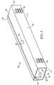
- reference numeral 10 generally denotes an information presentation device according to the present invention.
- the device 10 comprises an elongate housing 12 having two opposed end walls 14,16 respectively.
- the housing is rectangular and is fabricated from pressed sheet metal.
- a first opening 18 is provided in an upwardly facing wall 20 of the housing, the opening extending longitudinally between the two end walls 14,16.
- the upwardly facing wall 20 is advantageously provided with a second opening 22 positioned centrally between the end walls 14,16.
- the second opening 22 serves to accommodate an end of a preferably collapsable support rod 24.
- the support rod 24 is adapted to support a display sheet 26 in an erect condition.
- a rear surface 28 of the housing may be equipped with support rod storage means 30, for example in the form of a pair of clips, so that the support rod 24, or at least its constituent components, can be stored and/or transported together with the housing when the information presentation device is not being used.
- the information presentation device 10 further comprises a drum 32 having an outer surface 33, the drum extending about a longitudinal axis 34.
- the drum 32 is mounted for rotation in the housing 10 between the two end walls 14,16 such that the longitudinal axis 34 is substantially parallel to the first opening 18 in the housing.
- the drum 32 is intended to cooperate with the display sheet 26 such that the display sheet can be selectively wound onto and off the drum.
- the device according to the present invention further comprises attachment means, generally denoted 36 (see Fig. 3 and 6), for releasably attaching the display sheet 26 to the drum.
- the attachment means 36 comprises an attachment strip 38 for attachment, for example using adhesive, to one end of the display sheet, and receiving means 40 on the drum 32 for releasably engaging the attachment strip 38.
- the attachment strip and receiving means form a releasable mechanical connection.
- the attachment strip 38 and the receiving means 40 form a male/female joint in which the attachment strip comprises the male component of the joint.
- the receiving means 40 may be a longitudinally extending slot 42 having a tangential opening with a restriction to thereby delimit a chamber in the base of the slot.
- the slot 42 preferably extends the entire length of the drum 32.
- the chamber in the base of the slot is adapted to accommodate a bulbous lower portion 44 of the attachment strip 38 so that the attachment strip is constrained to rotate with the drum.
- the construction of the attachment means 36 permits the attachment strip 38 to be inserted in the longitudinal direction into the receiving means 40.
- the receiving means 40 is again a longitudinally extending slot 42.
- the outer surface 33 of the drum 32 is provided with a recessed arcuate portion 84 which at least partially delimits one edge 86 of the slot 42.
- the attachment strip 38 is also provided with an arcuate portion 88 which, when the attachment strip is engaged in the longitudinally extending slot, overlies the recessed arcuate portion 84 of the outer surface of the drum.
- the attachment strip 38 further comprises a longitudinally extending shoulder 90. As is most clearly shown in Fig.
- the shoulder 90 is adapted to abut the one edge 86 of the longitudinally extending slot 42 when the display sheet 26 is erected, i.e. when a force is applied to the display sheet in the direction of the arrow A.
- the construction of the attachment means 36 permits the attachment strip 38 to be inserted in a direction perpendicular to the longitudinal axis of the drum 32 into the receiving means 40.
- At least one end wall 14 of the housing 12 has an insertion opening 46 extending from an end of the first opening 18 in the housing.
- the insertion opening 46 is in the form of a slot and is arranged with respect to the drum 32 such that the attachment strip 38 can be brought into engagement with the receiving means 40 on the drum by inserting the attachment strip through the insertion opening 46 in a direction substantially parallel to the longitudinal axis 34 of the drum. In this manner, any display sheet which is mounted to an attachment strip 38 can be easily connected to the information presentation device without having to dismantle the device.
- the first opening 18 in the housing 12 is arranged with respect to the drum 32 such that the longitudinally extending slot 42 in the drum 32 can be positioned adjacent the first opening 18 seen in the radial direction to thereby allow the attachment strip 36 to be inserted into the slot 42 in a direction perpendicular to the longitudinal axis 34 of the drum.
- the drum 32 is preferably spring-biased such that when a display sheet is attached to the drum, the display sheet is drawn into the housing.
- the drum is hollow 32 and accommodates a biasing spring 48 mounted around a spindle 50 of the drum.
- the spindle is arranged for relative axial displacement with respect to the drum 32 against the action of the biasing spring.
- the spring biasing is adjustable by means of a tensioning device 52 accessible from outside the housing.
- the tensioning device 52 may comprise a slot 54 in one end of the spindle 50. Adjacent the end of the spindle there is provided a transversely extending engagement pin 56.
- the engagement pin 56 is arranged to cooperate with a rachet arrangement 58 mounted on the end wall 16 concentrically with the spindle 50.
- the rachet arrangement 58 has a centrally positioned through bore which is aligned with an opening 60 in the end wall 16.
- the engagement pin 56 is in cooperation with the rachet arrangement, the end of the spindle comprising the slot 54 lies immediately adjacent the opening 60 in the end wall.
- the rachet arrangement 58 prevents the spindle 50 from rotating under the influence of the spring biasing with respect to the drum 32.
- a bladed instrument may be inserted through the opening 60 in the end wall 16 to engage the slot 54 in the spindle 50.
- the spindle may then be displaced inwards, i.e. to the right as shown in Fig. 4 to bring the engagement pin 56 out of engagement with the rachet arrangement 58.
- the spindle may then by rotated with respect to the drum in order to alter the tension in the biasing spring.
- the bladed instrument may be withdrawn from the slot 54 to allow the engagement pin 56 to reengage the rachet arrangement.
- the receiving means 40 on the drum 32 be aligned with either the insertion opening 46 in the housing (Figs. 1 to 4) or the first opening 18 in the housing (Figs. 5 and 6).
- the drum 32 is provided with positioning means 62, the positioning means being accessible from outside the housing. Possible positioning means 62 are illustrated in Fig. 4. It is to be understood that identical positioning means may also be employed in the embodiment illustrated in Figs. 5 and 6.
- the positioning means may comprise an end plate 64 fixedly mounted to the drum 32 and constrained to rotate therewith.
- the end plate 64 displays an annular recess 66 located concentrically with the longitudinal axis 34 of the drum 32.
- the annular recess 66 comprises an inner facing surface which acts as a bearing surface for the drum and cooperates with a cylindrical support member 68 affixed to the end wall 14 of the housing.
- the cylindrical support member 68 is aligned with a positioning opening 70 in the end wall 14.
- the annular recess 66 further comprises a base section 72 provided with a slot 74.
- the end wall 14 of the housing may be provided with a locking opening 76 through which locking means in the form of e.g. a locking pin 78 may be inserted.
- the locking pin 78 is intended to engage a (not shown) recess or opening in the end plate 64 on the drum 32. In this manner, the locking means is accessible from outside the housing to effect locking of the drum when a display sheet is e.g. substantially fully unwound from the drum.
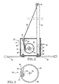
- the housing 12 may be provided with support means 80, for example in the form of two pairs of outwardly pivotable feet (Fig. 2).
- the information display device 10 may be delivered to the consumer either with the biasing spring 48 in a pretensioned or non-tensioned condition.
- the biasing spring 48 in a pretensioned or non-tensioned condition.
- a display sheet 26 may be mounted to the device by firstly bringing the receiving means 40 on the drum 32 into alignment with the insertion opening 46 in the end wall 14 of the housing. As has been explained above, this can be suitably attained by rotating the drum 32 via the positioning means 62. Thereafter, the attachment strip 38 to which the display sheet 26 is affixed is inserted through the insertion opening 46 in a direction substantially parallel to the longitudinal axis 34 of the drum 32 such that said attachment strip is brought into engagement with the receiving means 40 on the drum. The display sheet is then wound around the drum 32, suitably by means of the positioning means 62. Finally, the biasing spring 48 is tensioned by means of the tensioning device 52 so that the drum tends to retain the display sheet in the housing 12.
- the receiving means 40 on the drum is already predisposed in alignment with the insertion opening 46 in the end wall by means of the locking means 78.
- a display sheet 26 may be mounted to the device by inserting the attachment strip 38 through the insertion opening 46 in a direction substantially parallel to the longitudinal axis 34 of the drum 32 such that the attachment strip is brought into engagement with the receiving means 40 on the drum.
- the locking pin78 is then removed such that the display sheet 26 is caused to be wound around the drum as a result of the spring biasing of the drum.
- a display sheet 26 may be mounted to the device by firstly bringing the receiving means 40 on the drum 32 into alignment with the first opening 18 in the housing 18. As has been explained above, this can be suitably attained by rotating the drum 32 via the positioning means 62. Thereafter, the attachment strip 38 to which the display sheet 26 is affixed is inserted through the first opening 18 in a direction substantially perpendicular to the longitudinal axis 34 of the drum 32 such that said attachment strip is brought into engagement with the receiving means 40 on the drum. The display sheet is then wound around the drum 32, suitably by means of the positioning means 62. Finally, the biasing spring 48 is tensioned by means of the tensioning device 52 so that the drum tends to retain the display sheet in the housing 12.
- the receiving means 40 on the drum is already predisposed in alignment with the first opening 18 in the housing by means of the locking means 78.
- a display sheet 26 may be mounted to the device by inserting the attachment strip 38 through the first opening 18 in a direction substantially perpendicular to the longitudinal axis 34 of the drum 32 such that the attachment strip is brought into engagement with the receiving means 40 on the drum.
- the locking pin78 is then removed such that the display sheet 26 is caused to be wound around the drum as a result of the spring biasing of the drum.
- the display sheet 26 is preferably provided with an upper support strip 80.
- the upper support strip 80 lies over the first opening 18 in the upwardly facing wall 20 of the housing.
- the upwardly facing wall 20 of the housing may be provided with a recess 82 adjacent the first opening 18. In this manner, a user may more easily grasp the upper support strip 80 by inserting his/her fingers into the recess 82.
- the support rod 24 is assembled and inserted into the second opening 22 in the upwardly facing wall of the housing.
- the upper support strip 80 is grasped and drawn upwardly, thereby causing the drum 32 to rotate against the action of the biasing spring.
- the upper support strip is hooked over the remote end of the support rod to thereby maintain the display sheet in an erect condition.
- the upper support strip 80 is lifted from the support rod 24 and, under the action of the spring biasing, the drum 32 rotates to draw the display sheet into the housing.
- the support rod 24 may be integrated with the housing 12.
Abstract
Description
- The present invention relates to an information presentation device according to the preamble of claim 1. The invention further relates to methods of mounting a display sheet to an information presentation device.
- Various portable information presentation devices are known which include a display sheet wound onto a drum, the drum being journalled for rotation in an elongate housing. The housing is provided with a slot through which the display sheet passes. The display sheet can be unwound from the drum against the action of a biasing spring and maintained in an upright position to thereby display information printed on one side of the display sheet. One such information presentation device is disclosed in US-A-5 798 861.
- A disadvantage with previously known devices is that, should it be desirable to change the information which is to be displayed, the device has to be disassembled, the original display sheet must be detached from the drum and a new sheet attached in its place. Often, the display sheet is adhered to the drum, thereby rendering the task of exchanging the display sheet more difficult. Due to the perceived awkwardness of this operation, it is not uncommon for a user simply to order a complete new device with preprinted information.
- According to its abstract, US-A- 3 724 524 discloses a projection screen having a spring roller with a fabric-locking groove comprised of opposed side walls stepped on the roller periphery to the thickness of the fabric for producing safe mounting and flat hanging of picture surfaces, the side walls of which groove outwardly converge on a gap in the roller periphery of width equal to about twice the thickness of the screen fabric forming an inwardly-bent, wedging channel for locking on a metal strip clamped to the inner edge of the fabric screen. The metal strip and associated fabric is inserted into the groove in the longitudinal direction of the roller once an end cap of the roller has been removed.
- It is therefore an object of the present invention to provide an information presentation device in which exchange of the information which is to be presented is facilitated.
- This object is achieved in accordance with the present invention by an information presentation device according to claim 1.
- It is a further object of the present invention to provide a method of mounting a display sheet to an information presentation device, which method facilitates exchange of the display sheet.
- This object is achieved in accordance with the present invention by a method of mounting a display sheet to an information presentation device, said device comprising:
- an elongate housing having two opposed end walls and a first opening extending longitudinally between said end walls;
- a spring-biased drum extending about a longitudinal axis and mounted for rotation in said housing between said end walls such that said longitudinal axis is substantially parallel to said first opening in said housing;
- attachment means for attaching a display sheet to said drum such that said display sheet
can be wound around said drum, said attachment means comprising:
- an attachment strip attached to one end of said display sheet, and
- receiving means on said drum for releasably engaging said attachment strip;
said method comprising the steps of:
- bringing said receiving means on said drum into alignment with an insertion opening in one of said end walls of said housing;
- inserting said attachment strip through said insertion opening in a direction substantially parallel to said longitudinal axis such that said attachment strip is brought into engagement with said receiving means on said drum;
- winding said display sheet around said drum, and
- tensioning said spring-biased drum such that said drum tends to retain said display sheet in said housing.
-
- The above object is also attained in accordance with the present invention by a method of mounting a display sheet to an information presentation device, said device comprising:
- an elongate housing having two opposed end walls and a first opening extending longitudinally between said end walls;
- a pretensioned spring-biased drum extending about a longitudinal axis and mounted for rotation in said housing between said end walls such that said longitudinal axis is substantially parallel to said first opening in said housing;
- attachment means for attaching a display sheet to said drum such that said display sheet
can be wound around said drum, said attachment means comprising:
- an attachment strip attached to one end of said display sheet, and
- receiving means on said drum for releasably engaging said attachment strip; and
- locking means for locking said pretensioned spring-biased drum such that said receiving
means on said drum is aligned with an insertion opening in an end wall of said housing;
said method comprising the steps of:
- inserting said attachment strip through said insertion opening in a direction substantially parallel to said longitudinal axis such that said attachment strip is brought into engagement with said receiving means on said drum; and
- releasing said locking means such that said display sheet is caused to be wound around said drum.
-
- The above object is further achieved by a method of mounting a display sheet to an information presentation device, said device comprising:
- an elongate housing having two opposed end walls and a first opening extending longitudinally between said end walls;
- a spring-biased drum extending about a longitudinal axis and mounted for rotation in said housing between said end walls such that said longitudinal axis is substantially parallel to said first opening in said housing;
- attachment means for attaching a display sheet to said drum such that said display
sheet can be wound around said drum, said attachment means comprising:
- an attachment strip attached to one end of said display sheet, and
- receiving means on said drum for releasably engaging said attachment strip; said method comprising the steps of:
- bringing said receiving means on said drum into alignment with said first opening in said elongate housing;
- inserting said attachment strip through said elongate opening in a direction substantially perpendicular to said longitudinal axis such that said attachment strip is brought into engagement with said receiving means on said drum;
- winding said display sheet around said drum, and
- tensioning said spring-biased drum such that said drum tends to retain said display sheet in said housing.
-
- The above object is also attained in accordance with the present invention by a method of mounting a display sheet to an information presentation device, said device comprising:
- an elongate housing having two opposed end walls and a first opening extending longitudinally between said end walls;
- a pretensioned spring-biased drum extending about a longitudinal axis and mounted for rotation in said housing between said end walls such that said longitudinal axis is substantially parallel to said first opening in said housing;
- attachment means for attaching a display sheet to said drum such that said display
sheet can be wound around said drum, said attachment means comprising:
- an attachment strip attached to one end of said display sheet, and
- receiving means on said drum for releasably engaging said attachment strip; and
- locking means for locking said pretensioned spring-biased drum such that said receiving means on said drum is aligned with said first opening in said housing; said method comprising the steps of:
- inserting said attachment strip through said first opening in a direction substantially perpendicular to said longitudinal axis such that said attachment strip is brought into engagement with said receiving means on said drum; and
- releasing said locking means such that said display sheet is caused to be wound around said drum.
-
- Since, in accordance with the present invention, the attachment strip to which a display sheet may be affixed can be inserted and removed from the information presentation device without the need to dismantle the device, one and the same information presentation device can effectively be used together with many different display sheets.
- Preferred embodiments of the present invention are detailed in the dependent claims.
- The present invention will be described in the following by way of example only and with reference to the attached drawings, in which:
- Fig. 1
- is a schematic perspective view of a first embodiment of an information presentation device according to the present invention viewed from behind;
- Fig. 2
- is a schematic end view of the device according to Fig. 1 equipped with a display sheet;
- Fig. 3
- is a schematic end view of a drum forming part of the device according to Fig. 1;
- Fig. 4
- is a schematic sectional plan view of the drum and end walls of the device according to Fig. 1;
- Fig. 5
- is a schematic perspective view of a second embodiment of a drum for use in an information presentation device according to the present invention; and
- Fig. 6
- is an end view on a larger scale of the drum illustrated in Fig. 5.
- In the drawings,
reference numeral 10 generally denotes an information presentation device according to the present invention. Thedevice 10 comprises anelongate housing 12 having twoopposed end walls first opening 18 is provided in an upwardly facingwall 20 of the housing, the opening extending longitudinally between the twoend walls wall 20 is advantageously provided with asecond opening 22 positioned centrally between theend walls second opening 22 serves to accommodate an end of a preferablycollapsable support rod 24. As will be apparent from the following description, thesupport rod 24 is adapted to support adisplay sheet 26 in an erect condition. Arear surface 28 of the housing may be equipped with support rod storage means 30, for example in the form of a pair of clips, so that thesupport rod 24, or at least its constituent components, can be stored and/or transported together with the housing when the information presentation device is not being used. - With particular reference to Figs. 2, 4, 5 and 6, the
information presentation device 10 further comprises adrum 32 having anouter surface 33, the drum extending about alongitudinal axis 34. Thedrum 32 is mounted for rotation in thehousing 10 between the twoend walls longitudinal axis 34 is substantially parallel to thefirst opening 18 in the housing. Thedrum 32 is intended to cooperate with thedisplay sheet 26 such that the display sheet can be selectively wound onto and off the drum. To achieve this, the device according to the present invention further comprises attachment means, generally denoted 36 (see Fig. 3 and 6), for releasably attaching thedisplay sheet 26 to the drum. - In accordance with the present invention, the attachment means 36 comprises an
attachment strip 38 for attachment, for example using adhesive, to one end of the display sheet, and receiving means 40 on thedrum 32 for releasably engaging theattachment strip 38. In this manner, the attachment strip and receiving means form a releasable mechanical connection. Preferably, theattachment strip 38 and the receiving means 40 form a male/female joint in which the attachment strip comprises the male component of the joint. Thus, in one embodiment of the invention illustrated in Figs. 1 to 4, the receiving means 40 may be a longitudinally extendingslot 42 having a tangential opening with a restriction to thereby delimit a chamber in the base of the slot. Theslot 42 preferably extends the entire length of thedrum 32. The chamber in the base of the slot is adapted to accommodate a bulbouslower portion 44 of theattachment strip 38 so that the attachment strip is constrained to rotate with the drum. As will be described below, the construction of the attachment means 36 permits theattachment strip 38 to be inserted in the longitudinal direction into the receiving means 40. - In a second embodiment of the invention illustrated in Figs. 5 and 6, the receiving means 40 is again a longitudinally extending
slot 42. In this embodiment, theouter surface 33 of thedrum 32 is provided with a recessedarcuate portion 84 which at least partially delimits oneedge 86 of theslot 42. Theattachment strip 38 is also provided with anarcuate portion 88 which, when the attachment strip is engaged in the longitudinally extending slot, overlies the recessedarcuate portion 84 of the outer surface of the drum. To ensure that theattachment strip 38 and thedrum 32 will co-rotate, theattachment strip 38 further comprises alongitudinally extending shoulder 90. As is most clearly shown in Fig. 6, theshoulder 90 is adapted to abut the oneedge 86 of thelongitudinally extending slot 42 when thedisplay sheet 26 is erected, i.e. when a force is applied to the display sheet in the direction of the arrow A. As will be described later, the construction of the attachment means 36 permits theattachment strip 38 to be inserted in a direction perpendicular to the longitudinal axis of thedrum 32 into the receiving means 40. - In terms of the first embodiment, and as is most clearly illustrated in Figs. 1 and 2, at least one
end wall 14 of thehousing 12 has aninsertion opening 46 extending from an end of thefirst opening 18 in the housing. Theinsertion opening 46 is in the form of a slot and is arranged with respect to thedrum 32 such that theattachment strip 38 can be brought into engagement with the receiving means 40 on the drum by inserting the attachment strip through theinsertion opening 46 in a direction substantially parallel to thelongitudinal axis 34 of the drum. In this manner, any display sheet which is mounted to anattachment strip 38 can be easily connected to the information presentation device without having to dismantle the device. - In terms of the second embodiment, the
first opening 18 in thehousing 12 is arranged with respect to thedrum 32 such that thelongitudinally extending slot 42 in thedrum 32 can be positioned adjacent thefirst opening 18 seen in the radial direction to thereby allow theattachment strip 36 to be inserted into theslot 42 in a direction perpendicular to thelongitudinal axis 34 of the drum. - For both embodiments, the
drum 32 is preferably spring-biased such that when a display sheet is attached to the drum, the display sheet is drawn into the housing. In a manner known per se, and as is illustrated in Fig. 4, the drum is hollow 32 and accommodates a biasingspring 48 mounted around aspindle 50 of the drum. The spindle is arranged for relative axial displacement with respect to thedrum 32 against the action of the biasing spring. In a preferred embodiment of the invention, the spring biasing is adjustable by means of atensioning device 52 accessible from outside the housing. Thetensioning device 52 may comprise aslot 54 in one end of thespindle 50. Adjacent the end of the spindle there is provided a transversely extendingengagement pin 56. Theengagement pin 56 is arranged to cooperate with arachet arrangement 58 mounted on theend wall 16 concentrically with thespindle 50. Therachet arrangement 58 has a centrally positioned through bore which is aligned with anopening 60 in theend wall 16. When theengagement pin 56 is in cooperation with the rachet arrangement, the end of the spindle comprising theslot 54 lies immediately adjacent theopening 60 in the end wall. Therachet arrangement 58 prevents thespindle 50 from rotating under the influence of the spring biasing with respect to thedrum 32. In order to alter the tension in the biasingspring 48, a bladed instrument may be inserted through theopening 60 in theend wall 16 to engage theslot 54 in thespindle 50. The spindle may then be displaced inwards, i.e. to the right as shown in Fig. 4 to bring theengagement pin 56 out of engagement with therachet arrangement 58. The spindle may then by rotated with respect to the drum in order to alter the tension in the biasing spring. Once the desired tension is achieved, the bladed instrument may be withdrawn from theslot 54 to allow theengagement pin 56 to reengage the rachet arrangement. - In order to be able to insert or remove an information sheet, it is necessary that the receiving means 40 on the
drum 32 be aligned with either theinsertion opening 46 in the housing (Figs. 1 to 4) or thefirst opening 18 in the housing (Figs. 5 and 6). To facilitate the alignment operation, in a preferred embodiment of the invention thedrum 32 is provided with positioning means 62, the positioning means being accessible from outside the housing. Possible positioning means 62 are illustrated in Fig. 4. It is to be understood that identical positioning means may also be employed in the embodiment illustrated in Figs. 5 and 6. Thus, the positioning means may comprise anend plate 64 fixedly mounted to thedrum 32 and constrained to rotate therewith. Theend plate 64 displays anannular recess 66 located concentrically with thelongitudinal axis 34 of thedrum 32. Theannular recess 66 comprises an inner facing surface which acts as a bearing surface for the drum and cooperates with acylindrical support member 68 affixed to theend wall 14 of the housing. Thecylindrical support member 68 is aligned with apositioning opening 70 in theend wall 14. Theannular recess 66 further comprises abase section 72 provided with aslot 74. By inserting a bladed instrument through thepositioning opening 70 in theend wall 14 so that the instrument engages theslot 74, the angular position of thedrum 32 can be adjusted. - In certain circumstances, for example if the information presentation device is delivered with the biasing
spring 48 in a pretensioned condition, it is necessary to be able to lock thedrum 32 in a position at which the receiving means 40 on thedrum 32 is aligned with either theinsertion opening 46 or thefirst opening 18 in the housing. To this effect, theend wall 14 of the housing may be provided with a lockingopening 76 through which locking means in the form of e.g. a lockingpin 78 may be inserted. The lockingpin 78 is intended to engage a (not shown) recess or opening in theend plate 64 on thedrum 32. In this manner, the locking means is accessible from outside the housing to effect locking of the drum when a display sheet is e.g. substantially fully unwound from the drum. - In order to ensure stability of the information display device, particularly when the display sheet is erect, the
housing 12 may be provided with support means 80, for example in the form of two pairs of outwardly pivotable feet (Fig. 2). - The
information display device 10 according to the present invention may be delivered to the consumer either with the biasingspring 48 in a pretensioned or non-tensioned condition. In the following, methods of mounting a display sheet to both embodiment of the device will be described for these two conditions. - For the embodiment illustrated in Figs. 1 to 4, when the information display device is delivered with the biasing spring in a non-tensioned condition, a
display sheet 26 may be mounted to the device by firstly bringing the receiving means 40 on thedrum 32 into alignment with theinsertion opening 46 in theend wall 14 of the housing. As has been explained above, this can be suitably attained by rotating thedrum 32 via the positioning means 62. Thereafter, theattachment strip 38 to which thedisplay sheet 26 is affixed is inserted through theinsertion opening 46 in a direction substantially parallel to thelongitudinal axis 34 of thedrum 32 such that said attachment strip is brought into engagement with the receiving means 40 on the drum. The display sheet is then wound around thedrum 32, suitably by means of the positioning means 62. Finally, the biasingspring 48 is tensioned by means of thetensioning device 52 so that the drum tends to retain the display sheet in thehousing 12. - When the information display device is delivered with the biasing spring in a tensioned condition, the receiving means 40 on the drum is already predisposed in alignment with the
insertion opening 46 in the end wall by means of the locking means 78. Adisplay sheet 26 may be mounted to the device by inserting theattachment strip 38 through theinsertion opening 46 in a direction substantially parallel to thelongitudinal axis 34 of thedrum 32 such that the attachment strip is brought into engagement with the receiving means 40 on the drum. The locking pin78 is then removed such that thedisplay sheet 26 is caused to be wound around the drum as a result of the spring biasing of the drum. - In terms of the embodiment illustrated in Figs. 5 and 6, when the information display device is delivered with the biasing spring in a non-tensioned condition, a
display sheet 26 may be mounted to the device by firstly bringing the receiving means 40 on thedrum 32 into alignment with thefirst opening 18 in thehousing 18. As has been explained above, this can be suitably attained by rotating thedrum 32 via the positioning means 62. Thereafter, theattachment strip 38 to which thedisplay sheet 26 is affixed is inserted through thefirst opening 18 in a direction substantially perpendicular to thelongitudinal axis 34 of thedrum 32 such that said attachment strip is brought into engagement with the receiving means 40 on the drum. The display sheet is then wound around thedrum 32, suitably by means of the positioning means 62. Finally, the biasingspring 48 is tensioned by means of thetensioning device 52 so that the drum tends to retain the display sheet in thehousing 12. - When the information display device is delivered with the biasing spring in a tensioned condition, the receiving means 40 on the drum is already predisposed in alignment with the
first opening 18 in the housing by means of the locking means 78. Adisplay sheet 26 may be mounted to the device by inserting theattachment strip 38 through thefirst opening 18 in a direction substantially perpendicular to thelongitudinal axis 34 of thedrum 32 such that the attachment strip is brought into engagement with the receiving means 40 on the drum. The locking pin78 is then removed such that thedisplay sheet 26 is caused to be wound around the drum as a result of the spring biasing of the drum. - As is best shown in Fig. 2, the
display sheet 26 is preferably provided with anupper support strip 80. When the display sheet is wound on thedrum 32, theupper support strip 80 lies over thefirst opening 18 in the upwardly facingwall 20 of the housing. To facilitate raising of the display sheet, the upwardly facingwall 20 of the housing may be provided with arecess 82 adjacent thefirst opening 18. In this manner, a user may more easily grasp theupper support strip 80 by inserting his/her fingers into therecess 82. To erect the display sheet, thesupport rod 24 is assembled and inserted into thesecond opening 22 in the upwardly facing wall of the housing. Theupper support strip 80 is grasped and drawn upwardly, thereby causing thedrum 32 to rotate against the action of the biasing spring. The upper support strip is hooked over the remote end of the support rod to thereby maintain the display sheet in an erect condition. - To collapse the
display sheet 26, theupper support strip 80 is lifted from thesupport rod 24 and, under the action of the spring biasing, thedrum 32 rotates to draw the display sheet into the housing. - It is to be understood that the invention has been described above by way of example only and that various modifications and alternative embodiments within the scope of the appended claims will be apparent to the skilled person. For example, the
support rod 24 may be integrated with thehousing 12.
Claims (13)
- An information presentation device (10) comprising:characterized in that said attachment means (36) is configured such that said releasable mechanical connection is releasable while said drum (32) is within said elongate housing (12).an elongate housing (12) having two opposed end walls (14,16) and a first opening (18) extending longitudinally between said end walls;a drum (32) having an outer surface (33), said drum extending about a longitudinal axis (34) and mounted for rotation in said housing between said end walls (14,16) such that said longitudinal axis is substantially parallel to said first opening (18) in said housing; andattachment means (36) for attaching a display sheet (26) to said drum (32) such that said display sheet can be wound around said drum, said attachment means (36) comprising:an attachment strip (38) for attachment to one end of said display sheet, andreceiving means (40) on said drum for releasably engaging said attachment strip;said attachment strip (38) and said receiving means (40) forming a releasable mechanical connection;
- The information presentation device (10) as claimed in claim 1, characterized in that releasable mechanical connection is a male/female joint in which said attachment strip (38) comprises the male component of the joint.
- The information presentation device (10) as claimed in claim 2, characterized in that said receiving means (40) on said drum (32) is a longitudinally extending slot.
- The information presentation device (10) as claimed in any one of the preceding claims, characterized in that at least one of said end walls (14,16) of said housing has an insertion opening (46) extending from an end of said first opening (18), said insertion opening being arranged with respect to said drum (32) such that said attachment strip (38) can be brought into engagement with said receiving means (40) on said drum by inserting said attachment strip through said insertion opening (18) in a direction substantially parallel to said longitudinal axis (34).
- The information presentation device (10) as claimed in claim 3, characterized in that said outer surface (33) of said drum comprises a recessed arcuate portion (84) at least partially delimiting one edge (86) of said longitudinally extending slot in said drum (32), and in that said attachment strip (38) has an arcuate portion (88) which, when said attachment strip is engaged in said longitudinally extending slot, overlies said recessed arcuate portion (84).
- The information presentation device (10) as claimed in claim 5, characterized in that said attachment strip (38) comprises a longitudinally extending shoulder (90), said shoulder being adapted to abut said one edge (86) of said longitudinally extending slot in said drum (32) when said display sheet (26) is erected.
- The information presentation device (10) as claimed in any one of the preceding claims, characterized in that said drum (32) is spring-biased such that when a display sheet (26) is attached to said drum, said display sheet is drawn into said housing (12), said spring biasing being adjustable by means of a tensioning device (52) accessible from outside the housing.
- The information presentation device (10) as claimed in any one of the preceding claims, characterized in that said drum (32) is provided with positioning means (62), said positioning means being accessible from outside the housing to effect alignment of the receiving means (40) on said drum (32) with either said first opening (18) or said insertion opening (46).
- The information presentation device (10) as claimed in any one of the preceding claims, characterized in that said drum is provided with locking means (78) accessible from outside the housing to effect locking of the drum when a display sheet is substantially fully unwound from said drum (32).
- A method of mounting a display sheet (26) to an information presentation device (10), said device comprising:said method comprising the steps of:an elongate housing (12) having two opposed end walls (14,16) and a first opening (18) extending longitudinally between said end walls;a spring-biased drum (32) extending about a longitudinal axis (34) and mounted for rotation in said housing between said end walls such that said longitudinal axis is substantially parallel to said first opening (18) in said housing;attachment means (36) for attaching a display sheet to said drum (32) such that said display sheet can be wound around said drum, said attachment means comprising:an attachment strip (38) attached to one end of said display sheet, andreceiving means (40) on said drum for releasably engaging said attachment strip;bringing said receiving means (40) on said drum into alignment with an insertion opening (46) in one of said end walls of said housing;inserting said attachment strip (38) through said insertion opening in a direction substantially parallel to said longitudinal axis (34) such that said attachment strip is brought into engagement with said receiving means (40) on said drum;winding said display sheet around said drum, andtensioning said spring-biased drum (32) such that said drum tends to retain said display sheet in said housing (12).
- A method of mounting a display sheet (26) to an information presentation device (10), said device comprising:said method comprising the steps of:an elongate housing (12) having two opposed end walls (14,16) and a first opening (18) extending longitudinally between said end walls;a pretensioned spring-biased drum (32) extending about a longitudinal axis (34) and mounted for rotation in said housing between said end walls such that said longitudinal axis is substantially parallel to said first opening (18) in said housing;attachment means (36) for attaching a display sheet (26) to said drum (32) such that said display sheet can be wound around said drum, said attachment means comprising:an attachment strip (38) attached to one end of said display sheet, andreceiving means (40) on said drum for releasably engaging said attachment strip; andlocking means (78) for locking said pretensioned spring-biased drum (32) such that said receiving means (40) on said drum (32) is aligned with an insertion opening (46) in an end wall (14) of said housing;inserting said attachment strip (38) through said insertion opening (46) in a direction substantially parallel to said longitudinal axis (34) such that said attachment strip (38) is brought into engagement with said receiving means (40) on said drum; andreleasing said locking means (78) such that said display sheet is caused to be wound around said drum (32).
- A method of mounting a display sheet (26) to an information presentation device (10), said device comprising:said method comprising the steps of:an elongate housing (12) having two opposed end walls (14,16) and a first opening (18) extending longitudinally between said end walls;a spring-biased drum (32) extending about a longitudinal axis (34) and mounted for rotation in said housing between said end walls such that said longitudinal axis is substantially parallel to said first opening (18) in said housing;attachment means (36) for attaching a display sheet to said drum (32) such that said display sheet can be wound around said drum, said attachment means comprising:an attachment strip (38) attached to one end of said display sheet, andreceiving means (40) on said drum for releasably engaging said attachment strip;bringing said receiving means (40) on said drum into alignment with said first opening (18) in said elongate housing (12);inserting said attachment strip (38) through said elongate opening in a direction substantially perpendicular to said longitudinal axis (34) such that said attachment strip is brought into engagement with said receiving means (40) on said drum;winding said display sheet around said drum, andtensioning said spring-biased drum (32) such that said drum tends to retain said display sheet in said housing (12).
- A method of mounting a display sheet (26) to an information presentation device (10), said device comprising:said method comprising the steps of:an elongate housing (12) having two opposed end walls (14,16) and a first opening (18) extending longitudinally between said end walls;a pretensioned spring-biased drum (32) extending about a longitudinal axis (34) and mounted for rotation in said housing between said end walls such that said longitudinal axis is substantially parallel to said first opening (18) in said housing;attachment means (36) for attaching a display sheet (26) to said drum (32) such that said display sheet can be wound around said drum, said attachment means comprising:an attachment strip (38) attached to one end of said display sheet, andreceiving means (40) on said drum for releasably engaging said attachment strip; andlocking means (78) for locking said pretensioned spring-biased drum (32) such that said receiving means (40) on said drum (32) is aligned with said first opening (18) in said housing;inserting said attachment strip (38) through said first opening (18) in a direction substantially perpendicular to said longitudinal axis (34) such that said attachment strip (38) is brought into engagement with said receiving means (40) on said drum; andreleasing said locking means (78) such that said display sheet is caused to be wound around said drum (32).
Applications Claiming Priority (1)
| Application Number | Priority Date | Filing Date | Title |
|---|---|---|---|
| PCT/SE2000/001852 WO2002009080A1 (en) | 2000-09-25 | 2000-09-25 | Information presentation device |
Publications (3)
| Publication Number | Publication Date |
|---|---|
| EP1285421A1 EP1285421A1 (en) | 2003-02-26 |
| EP1285421B1 true EP1285421B1 (en) | 2004-01-28 |
| EP1285421B2 EP1285421B2 (en) | 2008-03-26 |
Family
ID=20279736
Family Applications (1)
| Application Number | Title | Priority Date | Filing Date |
|---|---|---|---|
| EP00966658A Expired - Lifetime EP1285421B2 (en) | 2000-09-25 | 2000-09-25 | Information presentation device |
Country Status (9)
| Country | Link |
|---|---|
| US (2) | US7040372B2 (en) |
| EP (1) | EP1285421B2 (en) |
| CN (1) | CN1284126C (en) |
| AT (1) | ATE258706T1 (en) |
| AU (1) | AU2000276972A1 (en) |
| CA (1) | CA2423412A1 (en) |
| DE (1) | DE60008027T3 (en) |
| ES (1) | ES2213610T5 (en) |
| WO (1) | WO2002009080A1 (en) |
Cited By (1)
| Publication number | Priority date | Publication date | Assignee | Title |
|---|---|---|---|---|
| DK178196B1 (en) * | 2009-09-01 | 2015-08-03 | Magsee Gmbh | Method and object and application for attaching posters |
Families Citing this family (29)
| Publication number | Priority date | Publication date | Assignee | Title |
|---|---|---|---|---|
| CN1284126C (en) * | 2000-09-25 | 2006-11-08 | 马克布莱斯股份公司 | Information presentation apparatus and method of mounting display panel to information presentation apparatus |
| GB2393030A (en) * | 2002-08-21 | 2004-03-17 | Marler Haley Exposystems Ltd | Roll-up banner display |
| EP1422683A1 (en) * | 2002-11-22 | 2004-05-26 | SUNCOVER s.r.l. | Supporting device for advertising screens or cloths |
| FR2858389A1 (en) * | 2003-07-30 | 2005-02-04 | Guy Doat | VARIABLE GEOMETRY BRACKET WITH PARALLELOGRAM STRUCTURE |
| ZA200406212B (en) * | 2003-08-04 | 2005-08-31 | Meyer Allen | Retractable display apparatus |
| US7207370B2 (en) * | 2004-03-25 | 2007-04-24 | Rite-Hite Holding Corporation | Retractable safety barrier |
| WO2006028424A2 (en) * | 2004-09-08 | 2006-03-16 | M. T Reklam Ve Pazarlama Tic. Ltd. Sti. | Embodiment for exhibiting advertising posters |
| DE202004015139U1 (en) * | 2004-09-27 | 2004-12-09 | My Art Gmbh | Projection screen has a fabric screen gripped at the corners by four flexible stays fitted to a support stand |
| US7614439B2 (en) * | 2004-10-05 | 2009-11-10 | Stephen Lukos | Roller tube having external slot for mounting sheet material |
| US7337567B2 (en) * | 2004-12-01 | 2008-03-04 | Skyline Displays, Inc. | Retractable banner stand with curvature means |
| US7963059B2 (en) * | 2004-12-01 | 2011-06-21 | Skyline Displays, Inc. | Tradeshow display formed of banner stands |
| ATE554475T1 (en) * | 2005-02-07 | 2012-05-15 | Expand Int Ab | BANNER STAND |
| US7300096B2 (en) * | 2005-04-04 | 2007-11-27 | Maguire Glenn A | Emergency vehicle blind apparatus |
| JP2010500488A (en) * | 2006-08-11 | 2010-01-07 | ロフレックス・ゲゼルシャフト・ミト・ベシュレンクテル・ハフツング・ウント・コンパニー・コマンデイトゲゼルシャフト | Closure and safety protection column |
| US20080105797A1 (en) * | 2006-10-27 | 2008-05-08 | Skyline Displays, Inc. | Curved retractable banner stand |
| MX2009014082A (en) | 2007-07-06 | 2010-03-01 | Rite Hite Holding Corp | Retractable safety barriers and methods of operating same. |
| US20090054219A1 (en) * | 2007-08-22 | 2009-02-26 | Hans Wu | Spool assembly |
| EP2148313A1 (en) * | 2008-07-21 | 2010-01-27 | Chatter B.V. | Advertising assembly |
| US8006420B2 (en) * | 2008-08-27 | 2011-08-30 | The Portables Exhibit Systems Limited | Retractable banner display stand |
| DE102009004983A1 (en) * | 2009-01-14 | 2010-07-15 | Durable Hunke & Jochheim Gmbh & Co. Kg | Display for sheet-shaped information carrier |
| GB2475469A (en) * | 2009-08-25 | 2011-05-25 | Robert Lewis Lewis | Barrier Apparatus Which Supports a Flexible Banner |
| US8793911B2 (en) * | 2009-10-15 | 2014-08-05 | Iconet Limited | Roller banners |
| US20120193594A1 (en) * | 2011-01-31 | 2012-08-02 | Mcafee Ralph Glenn | Perimeter access control system and method for use thereof |
| US9388541B2 (en) * | 2012-03-07 | 2016-07-12 | Chad Kunkel | Area delineator |
| CN202723295U (en) * | 2012-07-02 | 2013-02-13 | 常州霍克展示器材制造有限公司 | Roll-up banner base capable of being spliced seamlessly |
| KR102392360B1 (en) * | 2015-04-23 | 2022-04-29 | 엘지디스플레이 주식회사 | Rollable display apparatus |
| CN107991839B (en) * | 2017-12-28 | 2020-07-03 | 北京云庐科技有限公司 | Holographic projection device based on cloud BIM platform |
| USD909090S1 (en) | 2018-09-07 | 2021-02-02 | Fourds Limited | Extendable blind |
| EP4018042A1 (en) | 2019-08-21 | 2022-06-29 | Rite-Hite Holding Corporation | Impact resistant retractable safety barriers |
Citations (3)
| Publication number | Priority date | Publication date | Assignee | Title |
|---|---|---|---|---|
| US2589608A (en) * | 1948-05-06 | 1952-03-18 | Melville E Foster | Roller chart |
| US4794715A (en) * | 1985-02-26 | 1989-01-03 | Charles Cherwin | Motor-driven map holder |
| WO2000047508A1 (en) * | 1999-02-11 | 2000-08-17 | Expand International Ab | Device and method for preloading a spring and a reeling device including said device |
Family Cites Families (18)
| Publication number | Priority date | Publication date | Assignee | Title |
|---|---|---|---|---|
| US1562105A (en) * | 1924-05-31 | 1925-11-17 | Charles E Mcdonald | Window-shade roller |
| US1810849A (en) * | 1929-07-22 | 1931-06-16 | Alvin F Nye | Roller screen mounting |
| US1937209A (en) * | 1932-07-29 | 1933-11-28 | Higgin Mfg Co | Tension controlling device for rolling closures |
| US1947070A (en) * | 1932-07-29 | 1934-02-13 | Higgin Mfg Co | Device for controlling tension of spring rollers |
| US2589609A (en) * | 1949-08-17 | 1952-03-18 | Melville E Foster | Roller chart |
| US2822040A (en) * | 1953-08-20 | 1958-02-04 | Knox Mfg Company | Locking device for a picture screen |
| US2696249A (en) * | 1953-10-13 | 1954-12-07 | Da Lite Screen Company Inc | Screen web tensioner |
| US2812809A (en) * | 1954-12-16 | 1957-11-12 | Radiant Mfg Corp | Projection screen |
| US3018824A (en) * | 1957-04-01 | 1962-01-30 | Breneman Hartshorn Inc | Window shade fastening means |
| US3018924A (en) * | 1958-11-03 | 1962-01-30 | William C Tennesen | Particulate material dispenser means |
| US3228455A (en) * | 1963-12-31 | 1966-01-11 | Radiant Mfg Corp | Projection screen |
| US3263735A (en) * | 1964-04-22 | 1966-08-02 | Alcan Aluminum Corp | Roller tube |
| US3724524A (en) * | 1971-02-25 | 1973-04-03 | Da Lite Screen Co | Picture screen roller fabric attachment |
| DE3231091A1 (en) * | 1981-11-20 | 1983-05-26 | Helmut 8000 München Meinunger | Device for winding up a projection screen |
| FR2734387B1 (en) * | 1995-05-17 | 1997-07-18 | Doat Guy | INFORMATION PRESENTATION DEVICE, PARTICULARLY BY MEANS OF A MATERIAL COVERED ON A DRUM |
| US5778490A (en) * | 1996-01-24 | 1998-07-14 | Curtis; David B. | Tension device for live axle doors |
| JP3091165B2 (en) * | 1997-06-13 | 2000-09-25 | 株式会社有沢製作所 | Screen device |
| CN1284126C (en) * | 2000-09-25 | 2006-11-08 | 马克布莱斯股份公司 | Information presentation apparatus and method of mounting display panel to information presentation apparatus |
-
2000
- 2000-09-25 CN CN00819992.2A patent/CN1284126C/en not_active Expired - Fee Related
- 2000-09-25 WO PCT/SE2000/001852 patent/WO2002009080A1/en active IP Right Grant
- 2000-09-25 CA CA002423412A patent/CA2423412A1/en not_active Abandoned
- 2000-09-25 DE DE60008027T patent/DE60008027T3/en not_active Expired - Lifetime
- 2000-09-25 AT AT00966658T patent/ATE258706T1/en not_active IP Right Cessation
- 2000-09-25 ES ES00966658T patent/ES2213610T5/en not_active Expired - Lifetime
- 2000-09-25 AU AU2000276972A patent/AU2000276972A1/en not_active Abandoned
- 2000-09-25 EP EP00966658A patent/EP1285421B2/en not_active Expired - Lifetime
-
2003
- 2003-03-25 US US10/396,076 patent/US7040372B2/en not_active Expired - Fee Related
-
2006
- 2006-03-16 US US11/377,700 patent/US7185690B2/en not_active Expired - Fee Related
Patent Citations (3)
| Publication number | Priority date | Publication date | Assignee | Title |
|---|---|---|---|---|
| US2589608A (en) * | 1948-05-06 | 1952-03-18 | Melville E Foster | Roller chart |
| US4794715A (en) * | 1985-02-26 | 1989-01-03 | Charles Cherwin | Motor-driven map holder |
| WO2000047508A1 (en) * | 1999-02-11 | 2000-08-17 | Expand International Ab | Device and method for preloading a spring and a reeling device including said device |
Cited By (1)
| Publication number | Priority date | Publication date | Assignee | Title |
|---|---|---|---|---|
| DK178196B1 (en) * | 2009-09-01 | 2015-08-03 | Magsee Gmbh | Method and object and application for attaching posters |
Also Published As
| Publication number | Publication date |
|---|---|
| ES2213610T5 (en) | 2008-08-01 |
| DE60008027T2 (en) | 2004-10-21 |
| US20040020603A1 (en) | 2004-02-05 |
| DE60008027D1 (en) | 2004-03-04 |
| EP1285421B2 (en) | 2008-03-26 |
| EP1285421A1 (en) | 2003-02-26 |
| CN1505807A (en) | 2004-06-16 |
| US20060151124A1 (en) | 2006-07-13 |
| CA2423412A1 (en) | 2002-01-31 |
| DE60008027T3 (en) | 2008-08-14 |
| CN1284126C (en) | 2006-11-08 |
| WO2002009080A1 (en) | 2002-01-31 |
| US7040372B2 (en) | 2006-05-09 |
| ATE258706T1 (en) | 2004-02-15 |
| ES2213610T3 (en) | 2004-09-01 |
| AU2000276972A1 (en) | 2002-02-05 |
| US7185690B2 (en) | 2007-03-06 |
Similar Documents
| Publication | Publication Date | Title |
|---|---|---|
| EP1285421B1 (en) | Information presentation device | |
| US8006420B2 (en) | Retractable banner display stand | |
| US5231778A (en) | Sign system with rib lock mechanism | |
| US20100122780A1 (en) | Screen rolling device | |
| JP3002103B2 (en) | Portable screen | |
| EP1767408A2 (en) | Belt tension detecting apparatus and child seat | |
| JPH11142974A (en) | Portable type screen | |
| US6726145B1 (en) | Paper towel roll holder with adjustable pressure member | |
| US4239163A (en) | Roll holder friction brake | |
| EP0278081B1 (en) | A holder for one or more sheets of paper | |
| US20070070500A1 (en) | Retractable display apparatus | |
| US7716860B1 (en) | Retractable banner display | |
| JP2003527182A (en) | Display equipment for documents, textiles, photographs, etc. | |
| US6988690B2 (en) | Adhesive tape holder | |
| WO2021057861A1 (en) | Quickly adjustable musical instrument strap | |
| WO2002037459A3 (en) | Display apparatus | |
| JP2004308184A (en) | Fence tape support tool | |
| JP3385535B2 (en) | Double-sided double-sided screen and double-sided double-sided hanging scroll | |
| CN219285983U (en) | Suspension type advertisement display board | |
| CN220155085U (en) | Sign installation connecting piece | |
| US7145069B2 (en) | Motorized page turner | |
| US4991327A (en) | Card display | |
| JP3038010U (en) | Angle changing device and stand equipped with the same | |
| JP3060468U (en) | Display device | |
| RU26153U1 (en) | MEANS OF DISPLAYING MESSAGES AND IMAGES |
Legal Events
| Date | Code | Title | Description |
|---|---|---|---|
| PUAI | Public reference made under article 153(3) epc to a published international application that has entered the european phase |
Free format text: ORIGINAL CODE: 0009012 |
|
| 17P | Request for examination filed |
Effective date: 20021015 |
|
| AK | Designated contracting states |
Designated state(s): AT BE CH CY DE DK ES FI FR GB GR IE IT LI LU MC NL PT SE Kind code of ref document: A1 Designated state(s): AT BE CH CY DE DK ES FI FR GB GR IE IT LI LU MC NL PT SE |
|
| AX | Request for extension of the european patent |
Extension state: AL LT LV MK RO SI |
|
| 17Q | First examination report despatched |
Effective date: 20030210 |
|
| GRAP | Despatch of communication of intention to grant a patent |
Free format text: ORIGINAL CODE: EPIDOSNIGR1 |
|
| GRAS | Grant fee paid |
Free format text: ORIGINAL CODE: EPIDOSNIGR3 |
|
| GRAA | (expected) grant |
Free format text: ORIGINAL CODE: 0009210 |
|
| AK | Designated contracting states |
Kind code of ref document: B1 Designated state(s): AT BE CH CY DE DK ES FI FR GB GR IE IT LI LU MC NL PT SE |
|
| PG25 | Lapsed in a contracting state [announced via postgrant information from national office to epo] |
Ref country code: IT Free format text: LAPSE BECAUSE OF FAILURE TO SUBMIT A TRANSLATION OF THE DESCRIPTION OR TO PAY THE FEE WITHIN THE PRESCRIBED TIME-LIMIT;WARNING: LAPSES OF ITALIAN PATENTS WITH EFFECTIVE DATE BEFORE 2007 MAY HAVE OCCURRED AT ANY TIME BEFORE 2007. THE CORRECT EFFECTIVE DATE MAY BE DIFFERENT FROM THE ONE RECORDED. Effective date: 20040128 Ref country code: FI Free format text: LAPSE BECAUSE OF FAILURE TO SUBMIT A TRANSLATION OF THE DESCRIPTION OR TO PAY THE FEE WITHIN THE PRESCRIBED TIME-LIMIT Effective date: 20040128 Ref country code: AT Free format text: LAPSE BECAUSE OF FAILURE TO SUBMIT A TRANSLATION OF THE DESCRIPTION OR TO PAY THE FEE WITHIN THE PRESCRIBED TIME-LIMIT Effective date: 20040128 Ref country code: CH Free format text: LAPSE BECAUSE OF FAILURE TO SUBMIT A TRANSLATION OF THE DESCRIPTION OR TO PAY THE FEE WITHIN THE PRESCRIBED TIME-LIMIT Effective date: 20040128 Ref country code: CY Free format text: LAPSE BECAUSE OF FAILURE TO SUBMIT A TRANSLATION OF THE DESCRIPTION OR TO PAY THE FEE WITHIN THE PRESCRIBED TIME-LIMIT Effective date: 20040128 Ref country code: BE Free format text: LAPSE BECAUSE OF FAILURE TO SUBMIT A TRANSLATION OF THE DESCRIPTION OR TO PAY THE FEE WITHIN THE PRESCRIBED TIME-LIMIT Effective date: 20040128 Ref country code: LI Free format text: LAPSE BECAUSE OF FAILURE TO SUBMIT A TRANSLATION OF THE DESCRIPTION OR TO PAY THE FEE WITHIN THE PRESCRIBED TIME-LIMIT Effective date: 20040128 |
|
| REG | Reference to a national code |
Ref country code: GB Ref legal event code: FG4D |
|
| REG | Reference to a national code |
Ref country code: CH Ref legal event code: EP |
|
| REG | Reference to a national code |
Ref country code: IE Ref legal event code: FG4D |
|
| REF | Corresponds to: |
Ref document number: 60008027 Country of ref document: DE Date of ref document: 20040304 Kind code of ref document: P |
|
| REG | Reference to a national code |
Ref country code: SE Ref legal event code: TRGR |
|
| PG25 | Lapsed in a contracting state [announced via postgrant information from national office to epo] |
Ref country code: DK Free format text: LAPSE BECAUSE OF FAILURE TO SUBMIT A TRANSLATION OF THE DESCRIPTION OR TO PAY THE FEE WITHIN THE PRESCRIBED TIME-LIMIT Effective date: 20040428 Ref country code: GR Free format text: LAPSE BECAUSE OF FAILURE TO SUBMIT A TRANSLATION OF THE DESCRIPTION OR TO PAY THE FEE WITHIN THE PRESCRIBED TIME-LIMIT Effective date: 20040428 |
|
| LTIE | Lt: invalidation of european patent or patent extension |
Effective date: 20040128 |
|
| REG | Reference to a national code |
Ref country code: CH Ref legal event code: PL |
|
| REG | Reference to a national code |
Ref country code: ES Ref legal event code: FG2A Ref document number: 2213610 Country of ref document: ES Kind code of ref document: T3 |
|
| PG25 | Lapsed in a contracting state [announced via postgrant information from national office to epo] |
Ref country code: LU Free format text: LAPSE BECAUSE OF NON-PAYMENT OF DUE FEES Effective date: 20040925 |
|
| PG25 | Lapsed in a contracting state [announced via postgrant information from national office to epo] |
Ref country code: IE Free format text: LAPSE BECAUSE OF NON-PAYMENT OF DUE FEES Effective date: 20040927 |
|
| PG25 | Lapsed in a contracting state [announced via postgrant information from national office to epo] |
Ref country code: MC Free format text: LAPSE BECAUSE OF NON-PAYMENT OF DUE FEES Effective date: 20040930 |
|
| PLBI | Opposition filed |
Free format text: ORIGINAL CODE: 0009260 |
|
| PLBQ | Unpublished change to opponent data |
Free format text: ORIGINAL CODE: EPIDOS OPPO |
|
| ET | Fr: translation filed | ||
| PLAX | Notice of opposition and request to file observation + time limit sent |
Free format text: ORIGINAL CODE: EPIDOSNOBS2 |
|
| PLBQ | Unpublished change to opponent data |
Free format text: ORIGINAL CODE: EPIDOS OPPO |
|
| PLAB | Opposition data, opponent's data or that of the opponent's representative modified |
Free format text: ORIGINAL CODE: 0009299OPPO |
|
| 26 | Opposition filed |
Opponent name: EXPOLINC AB Effective date: 20041020 |
|
| R26 | Opposition filed (corrected) |
Opponent name: EXPOLINC AB Effective date: 20041020 |
|
| NLR1 | Nl: opposition has been filed with the epo |
Opponent name: EXPOLINC AB |
|
| NLR1 | Nl: opposition has been filed with the epo |
Opponent name: EXPOLINC AB |
|
| PLBB | Reply of patent proprietor to notice(s) of opposition received |
Free format text: ORIGINAL CODE: EPIDOSNOBS3 |
|
| REG | Reference to a national code |
Ref country code: IE Ref legal event code: MM4A |
|
| PLAY | Examination report in opposition despatched + time limit |
Free format text: ORIGINAL CODE: EPIDOSNORE2 |
|
| PLBC | Reply to examination report in opposition received |
Free format text: ORIGINAL CODE: EPIDOSNORE3 |
|
| PLAY | Examination report in opposition despatched + time limit |
Free format text: ORIGINAL CODE: EPIDOSNORE2 |
|
| PLBC | Reply to examination report in opposition received |
Free format text: ORIGINAL CODE: EPIDOSNORE3 |
|
| RAP2 | Party data changed (patent owner data changed or rights of a patent transferred) |
Owner name: MB INTRESSENTER AB |
|
| NLT2 | Nl: modifications (of names), taken from the european patent patent bulletin |
Owner name: MB INTRESSENTER AB Effective date: 20070801 |
|
| PG25 | Lapsed in a contracting state [announced via postgrant information from national office to epo] |
Ref country code: PT Free format text: LAPSE BECAUSE OF NON-PAYMENT OF DUE FEES Effective date: 20040628 |
|
| PUAH | Patent maintained in amended form |
Free format text: ORIGINAL CODE: 0009272 |
|
| STAA | Information on the status of an ep patent application or granted ep patent |
Free format text: STATUS: PATENT MAINTAINED AS AMENDED |
|
| 27A | Patent maintained in amended form |
Effective date: 20080326 |
|
| AK | Designated contracting states |
Kind code of ref document: B2 Designated state(s): AT BE CH CY DE DK ES FI FR GB GR IE IT LI LU MC NL PT SE |
|
| NLR2 | Nl: decision of opposition |
Effective date: 20080326 |
|
| REG | Reference to a national code |
Ref country code: SE Ref legal event code: RPEO |
|
| REG | Reference to a national code |
Ref country code: ES Ref legal event code: DC2A Date of ref document: 20080530 Kind code of ref document: T5 |
|
| NLR3 | Nl: receipt of modified translations in the netherlands language after an opposition procedure | ||
| PGFP | Annual fee paid to national office [announced via postgrant information from national office to epo] |
Ref country code: NL Payment date: 20080922 Year of fee payment: 9 |
|
| ET3 | Fr: translation filed ** decision concerning opposition | ||
| PGFP | Annual fee paid to national office [announced via postgrant information from national office to epo] |
Ref country code: ES Payment date: 20080930 Year of fee payment: 9 |
|
| REG | Reference to a national code |
Ref country code: GB Ref legal event code: 732E Free format text: REGISTERED BETWEEN 20090319 AND 20090325 |
|
| NLS | Nl: assignments of ep-patents |
Owner name: MARK BRIC DISPLAY AB Effective date: 20090223 |
|
| NLT1 | Nl: modifications of names registered in virtue of documents presented to the patent office pursuant to art. 16 a, paragraph 1 |
Owner name: MB INTRESSENTER AB |
|
| REG | Reference to a national code |
Ref country code: ES Ref legal event code: PC2A |
|
| REG | Reference to a national code |
Ref country code: FR Ref legal event code: TP |
|
| REG | Reference to a national code |
Ref country code: NL Ref legal event code: V1 Effective date: 20100401 |
|
| PG25 | Lapsed in a contracting state [announced via postgrant information from national office to epo] |
Ref country code: NL Free format text: LAPSE BECAUSE OF NON-PAYMENT OF DUE FEES Effective date: 20100401 |
|
| REG | Reference to a national code |
Ref country code: ES Ref legal event code: FD2A Effective date: 20110714 |
|
| PG25 | Lapsed in a contracting state [announced via postgrant information from national office to epo] |
Ref country code: ES Free format text: LAPSE BECAUSE OF NON-PAYMENT OF DUE FEES Effective date: 20110704 |
|
| PG25 | Lapsed in a contracting state [announced via postgrant information from national office to epo] |
Ref country code: ES Free format text: LAPSE BECAUSE OF NON-PAYMENT OF DUE FEES Effective date: 20090926 |
|
| PGFP | Annual fee paid to national office [announced via postgrant information from national office to epo] |
Ref country code: DE Payment date: 20130910 Year of fee payment: 14 |
|
| PGFP | Annual fee paid to national office [announced via postgrant information from national office to epo] |
Ref country code: FR Payment date: 20130927 Year of fee payment: 14 |
|
| REG | Reference to a national code |
Ref country code: DE Ref legal event code: R119 Ref document number: 60008027 Country of ref document: DE |
|
| REG | Reference to a national code |
Ref country code: FR Ref legal event code: ST Effective date: 20150529 |
|
| PG25 | Lapsed in a contracting state [announced via postgrant information from national office to epo] |
Ref country code: DE Free format text: LAPSE BECAUSE OF NON-PAYMENT OF DUE FEES Effective date: 20150401 |
|
| PG25 | Lapsed in a contracting state [announced via postgrant information from national office to epo] |
Ref country code: FR Free format text: LAPSE BECAUSE OF NON-PAYMENT OF DUE FEES Effective date: 20140930 |
|
| PGFP | Annual fee paid to national office [announced via postgrant information from national office to epo] |
Ref country code: SE Payment date: 20180919 Year of fee payment: 19 |
|
| PGFP | Annual fee paid to national office [announced via postgrant information from national office to epo] |
Ref country code: GB Payment date: 20190905 Year of fee payment: 20 |
|
| PG25 | Lapsed in a contracting state [announced via postgrant information from national office to epo] |
Ref country code: SE Free format text: LAPSE BECAUSE OF NON-PAYMENT OF DUE FEES Effective date: 20190926 |
|
| REG | Reference to a national code |
Ref country code: SE Ref legal event code: EUG |
|
| REG | Reference to a national code |
Ref country code: GB Ref legal event code: PE20 Expiry date: 20200924 |
|
| PG25 | Lapsed in a contracting state [announced via postgrant information from national office to epo] |
Ref country code: GB Free format text: LAPSE BECAUSE OF EXPIRATION OF PROTECTION Effective date: 20200924 |