EP1284526A2 - Electrical connector with shunt for hot mating and unmating - Google Patents
Electrical connector with shunt for hot mating and unmating Download PDFInfo
- Publication number
- EP1284526A2 EP1284526A2 EP02255520A EP02255520A EP1284526A2 EP 1284526 A2 EP1284526 A2 EP 1284526A2 EP 02255520 A EP02255520 A EP 02255520A EP 02255520 A EP02255520 A EP 02255520A EP 1284526 A2 EP1284526 A2 EP 1284526A2
- Authority
- EP
- European Patent Office
- Prior art keywords
- shunt
- terminal
- electrical connector
- connectors
- connector
- Prior art date
- Legal status (The legal status is an assumption and is not a legal conclusion. Google has not performed a legal analysis and makes no representation as to the accuracy of the status listed.)
- Granted
Links
Images


Classifications
-
- H—ELECTRICITY
- H01—ELECTRIC ELEMENTS
- H01R—ELECTRICALLY-CONDUCTIVE CONNECTIONS; STRUCTURAL ASSOCIATIONS OF A PLURALITY OF MUTUALLY-INSULATED ELECTRICAL CONNECTING ELEMENTS; COUPLING DEVICES; CURRENT COLLECTORS
- H01R13/00—Details of coupling devices of the kinds covered by groups H01R12/70 or H01R24/00 - H01R33/00
- H01R13/46—Bases; Cases
- H01R13/53—Bases or cases for heavy duty; Bases or cases for high voltage with means for preventing corona or arcing
-
- H—ELECTRICITY
- H01—ELECTRIC ELEMENTS
- H01R—ELECTRICALLY-CONDUCTIVE CONNECTIONS; STRUCTURAL ASSOCIATIONS OF A PLURALITY OF MUTUALLY-INSULATED ELECTRICAL CONNECTING ELEMENTS; COUPLING DEVICES; CURRENT COLLECTORS
- H01R13/00—Details of coupling devices of the kinds covered by groups H01R12/70 or H01R24/00 - H01R33/00
- H01R13/66—Structural association with built-in electrical component
- H01R13/70—Structural association with built-in electrical component with built-in switch
- H01R13/703—Structural association with built-in electrical component with built-in switch operated by engagement or disengagement of coupling parts, e.g. dual-continuity coupling part
- H01R13/7031—Shorting, shunting or bussing of different terminals interrupted or effected on engagement of coupling part, e.g. for ESD protection, line continuity
-
- H—ELECTRICITY
- H02—GENERATION; CONVERSION OR DISTRIBUTION OF ELECTRIC POWER
- H02H—EMERGENCY PROTECTIVE CIRCUIT ARRANGEMENTS
- H02H9/00—Emergency protective circuit arrangements for limiting excess current or voltage without disconnection
- H02H9/001—Emergency protective circuit arrangements for limiting excess current or voltage without disconnection limiting speed of change of electric quantities, e.g. soft switching on or off
- H02H9/004—Emergency protective circuit arrangements for limiting excess current or voltage without disconnection limiting speed of change of electric quantities, e.g. soft switching on or off in connection with live-insertion of plug-in units
Definitions
- This invention is related to electrical connectors of the type that can be mated and unmated. This invention is also related to the prevention of arcing between mating terminals as electrical connectors are mated or unmated in a hot condition. This invention is also related to the use of a shunt to provide a signal to close a relay to bypass current around the electrical connectors during mating and unmating to reduce the chance of arcing.
- Arcing can be a problem when electrical connectors are mated and unmated under load or in a hot condition. If arcing between mating electrical terminals does occur, it would normally occur when the terminals are initially mated or unmated and the terminals are either not in contact or have not been brought into sufficient contact to carry the current.
- Shunts have been used to common adjacent contacts in the same connector when unmated from a mating connector.
- shunts of this type are commonly used in air bag connector.
- applicants are unaware of the use of a single shunt in one of two mating connectors to provide a signal to a relay to bypass current around the electrical connector before mating terminals are in a position where they would be susceptible to arcing.
- the instant invention employs a single shunt to provide a signal for bypassing an electrical connector assembly before the mating terminals have reached a position in which arcing can occur between two terminals. Only a single shunt and a single lead needs to be added to an electrical connector. This reduces the number of leads that would be needed for a make first, break last sacrificial contact.
- the single lead can be connected to a switch, such as a Form C relay, that can be used in the electrical system of an automobile. The relay can be connected to a circuit path that bypasses the electrical connector assembly when a signal is received through the shunt to close the Form C relay.
- the relay is a solid state relay device such as that disclosed in US Patent No. 5,926,354 or, most preferably, that disclosed in US Patent Application No. 10/068,925, filed February 8, 2002.
- solid state relays including a power metal oxide semiconductor field effect transducer ("MOSFET").
- MOSFET power metal oxide semiconductor field effect transducer
- the circuitry of the relay floats when the power MOSFET is commanded OFF to prevent leakage currents from draining a battery.
- the disclosures of these references are incorporated herein by reference in their entirety.
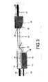
- Figures 1-3 are diagrammatic views that illustrate the use of a shunt 20 in an electrical connector assembly 2 employing two electrical connectors 10, 30.
- One connector 10 has female or receptacle terminals 14 and the other connector 30 has male terminals 34, such as pins or blades. Only a single mating pair of terminals 14, 34 is shown in Figures 1-3, but it should be understood that each connector 10, 30 can contain a plurality of terminals 14, 34.
- the male terminal 34 is mated with the female terminal 14.
- Each terminal 14, 34 is mounted in a connector housing 12, 32, which is illustrated in these diagrammatic views by plastic blocks.
- both the female and the male terminals 14, 34 are connected to wires 40, 42, which form a circuit path 50, as shown in Figure 4. It should be understood that either or both of these connectors 10, 30 could be a printed circuit board connector.
- the shunt 20 is also terminated to an external conductor or wire 40.
- the shunt 20 In the fully mated configuration of Figure 1, the shunt 20 is held in a deflected position in which the shunt 20 is electrically isolated from both the male terminal 34 and the female terminal 14.
- the shunt 20 engages an inclined ramp or camming surface 36 on the connector housing 32 containing a male terminal or pin 34. This camming surface 36 is located on the front of the connector housing 32 and slopes away from the male terminal 34, so that it deflects the shunt 20 outwardly, away from the male terminal 34.
- the two connectors 10, 30 would be held in the fully mated configuration by conventional connector latches, which do not form an essential element of this invention and are therefore not shown.
- the shunt could be part of a subassembly that is in turn included as a part of the connector housing containing the female terminals. Relative motion between a subassembly containing the shunt and the remainder of the electrical connector could result in deflection of the shunt to a disengaged position. Any number of means could be employed to shift the shunt to a disengaged position.
- Figure 2 is a schematic showing the two connectors 10, 30 in a partially mated configuration in which the leading edge of the male terminal 34 is just engaging a spring 16 in the female terminal 14.
- this schematic view could represent a position in which arcing could occur between the male terminal 34 and the female terminal 14 in the absence of any means for arc prevention or arc suppression. Even if contact between the two terminals 14, 34 is sufficient to prevent formation of an arc, continued unmating of the two electrical connectors 10, 30 will eventually bring the terminals 14, 34 into an arc susceptible position.
- the shunt 20 has moved from a deflected or disengaged position to a position in which the shunt 20 in the first connector 10 is engaging the male terminals 34 in the second connector 30. If the male terminal 34 is under load or is in a hot condition, the shunt 20 will then be brought to substantially the same voltage level as the male terminal 34, which it contacts. Since the shunt 20 is attached to an external conductor 38, a signal can be transmitted when the shunt 20 engages the male terminal 34 in the partially mated configuration of Figure 2.
- Figure 3 is a schematic of the two connectors 10, 30 in a disengaged or unmated configuration.
- the male terminal 34 has been completely disengaged from the female terminal 14 to open the circuit path 50 ( Figure 4) formerly established by mating the two electrical connectors 10, 30.
- Figure 3 also shows that the shunt 20 is disengaged from the male terminal 34.
- the shunt 20 has returned to a disengaged position.
- the shunt 20 now extends in front of the mating end 18 of the female terminal 14 and into the path traversed by the male terminal 34 during mating and unmating. In this position the shunt 20 is electrically isolated from both terminals 14, 34.
- Figures 1-3 show the relative positions of the shunt 20 first in the fully mated configuration, then in the partially mated configuration and then in the fully unmated configuration. Since arcing is generally more critical during unmating under load than during mating, this sequence shows the positions of the shunt 20 in relation to the two terminals 14, 34 in the more critical of the sequences in which arcing might occur. Of course the shunt 20 would function in the same way when the two connectors 10, 30 are mated. As shown in Figure 3, the shunt 20 is in the path of the male terminal 34, which must engage the shunt 20 before it engages the receptacle terminal 34.
- the shunt 20 is energized before the receptacle terminal 14, when the male terminal 34 is at a relatively higher potential.
- This voltage rise on the shunt 20 provides a signal or provides the means for closing a Form C relay 60, as will be discussed with reference to Figure 4.
- the shunt 20 engages the male terminal 34 in the embodiment illustrated in Figures 1-3, it should be understood that the positions of the male and female terminals 34, 14 could be reversed relative to the shunt 20.
- the shunt 20 it will only be necessary for the shunt 20 to engage the terminal 34 that is at a different potential when the two connectors 10, 30 are unmated under load. It is also not necessary for the shunt 20 to engage a terminal in the opposite connector. For example, it would be possible for the shunt to engage the terminal in the same connector in the partially mated configuration, and still be isolated from the terminal in the same connector when unmated.
- a camming projection in the opposite connector, which engages the shunt so as to deflect it into the engaged position only when the connectors are in the partially mated configuration.
- a bump on the opposite connector could engage a protrusion on the shunt during a portion of the travel of the two connectors during mating and unmating.
- Other similar configuration could be employed to bias the shunt into contact with the appropriate terminal in the partially mated configuration.
- FIG. 4 The circuit in which the connector assembly 2 is used is shown in Figure 4.
- the connector assembly 2 is in the partially mated configuration with the shunt 20 engaging contact or terminal 34.
- the diagram of Figure 4 shows how a shunt mechanism 20 could be used to divert power away form contacts 14, 34 if the shunt 20 is attached to a relay coil 62.
- the relay 60 When the shunt 20 is in contact with the male terminal or blade 34, the relay 60 will be in the open position as shown in Figure 4, and the power will be diverted from the contacts or terminals 14, 34 through bypass circuit 52. With power diverted away from the contacts 14, 34, the connector assembly 2 can mate and unmate with no load and therefore no arc.
- the circuit shown in Figure 4 is intended to be used in a 42 volt automotive electrical system with the male terminal 34 being connected to a 42 volt voltage source 70.
- the receptacle terminal 14 in the other connector 10 is connected to a 4.2 load 72, which is in turn connected to ground.
- a Form C relay 60 is connected to a bypass circuit path 52. Normally relay switch contact 66 is closed and current flows from the source through the mated connector assembly 2 to the load. However, when switch contact 64 is momentarily closed, current flows through the bypass circuit 52 and not through the connector assembly 2.
- a Form C mini or micro 280 relay is used.
- the switch contact 66 When the connector assembly is in the fully mated configuration or when it is completely disconnected the switch contact 66 is closed. It is only when the shunt 20 engages the pin 34 that the relay coil 62 is energized to momentarily close the switch contact 64 to bypass current around the connector assembly 2.
- the relay coil 62 is a 42 volt relay with a coil resistance of approximately 900 .
- the relay coil 62 is connected in a separate circuit path 54 to the shunt 20 and to ground. When the shunt 20 contacts the male terminal 34, which is at 42 volts, a current of 42mA flows in the coil circuit path 54.
- the relay coil 62 will only be energized when the connector assembly 2 is in the partially mated configuration.
- the switch contact 64 is closed and current is diverted along the bypass circuit path 52 so that no current flows through the connector assembly 2. Since the switch contact 64 is closed before the two terminals 14, 34 reach an arc susceptible position, the two terminals 14, 34 will be at the same potential when disconnected, or initially connected, so no potential difference will exist and no arcing can occur. Mating and unmating of the two connectors 10, 30 thus always occurs in a no load condition. It has been found that at normal mating and unmating speeds, the switch contact 64 will not open before the two terminals 14, 34 are either fully unmated or fully mated, or in other words until the terminals 14, 24 are no longer in an arc susceptible position.
- the shunt 20 provides a signal or a current to energize the relay coil 62, all of the arc susceptible terminal pairs can be wired through a switch or switches in this manner with one shunt being used to activate one or more relay coils. It should also be understood that the shunt 20 need not be connected to a relay 60, but could be used to provide a signal to other conventional power switching devices in a manner that would be apparent to one of ordinary skill in the art.
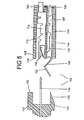
- FIG. 5 shows a typical connector assembly 102 with which this invention could be employed.
- This connector assembly 102 includes a printed circuit board header 130 with one terminal pin 134 mounted in an insulative housing 132. Each pin 134 in the header 130 is normally connected to a conventional conductor trace on a printed circuit board, not shown.
- This printed circuit board header 130 is typical of standard printed circuit board headers that are commonly used in automotive applications.
- the header housing 132 has an inclined camming surface 136 located adjacent a mating end 133 of the header 130. This inclined surface 136 slopes away from the center of the header130, and is positioned to deflect the shunt 120 in the plug connector 110 that mates with the printed circuit board header 130.
- the plug connector 110 includes at least one receptacle or female terminal or contact 114 that is matable to one of the pins 134 in the header 130. It should be understood that multiple pins and receptacle contact or terminals could be present in this connector assembly 102. Each receptacle terminal 114 is positioned within a terminal cavity 115 in the molded plug housing 112, and can be crimped to an external wire 140. A spring beam 116 on the mating end 118 of the receptacle contacts 114 will engage the corresponding pin 134 when the two connectors 110, 130 are fully mated.
- the shunt 120 is located in a separate shunt housing cavity 119 and is terminated to a lead 126 by using a conventional wire crimp 124.
- a deflectable contact section 122 of the shunt 120 extends beyond the front face 113 of the plug housing 112 and in front of the mating end 118 of the receptacle terminal 112. In this position the pin 134 will engage the shunt 120 before engaging the receptacle contact 114, and will be in contact with the shunt 120 as the connectors 110, 130 are unmated and the terminals 114, 124 are in an arc susceptible position.
Landscapes
- Details Of Connecting Devices For Male And Female Coupling (AREA)
- Connector Housings Or Holding Contact Members (AREA)
- Coupling Device And Connection With Printed Circuit (AREA)
Abstract
Description
Claims (20)
- A circuit comprising an electrical connector assembly (20) and a switch (64), wherein:the electrical connector assembly includes first (10) and second (30) matable electrical connectors, each connector including at least one terminal (14, 34) mounted in a housing (12, 32), the first connector (10) also including a shunt (20), the shunt (20) being maintained in an open position when the two connectors (10, 30) are fully mated, the shunt (20) being movable to close a first circuit path (54) including a terminal (34) in the second connector (30) as the two connectors (10, 30) are unmated, before the terminal (34) in the second connector (30) is disengaged from a mating terminal (14) in the first connector (10); and wherein,the shunt (20) is connected to a relay (60) when the shunt (20) closes the first circuit path (54) including the terminal (34) in the second connector (30); and wherein,the relay is connected to a second circuit path (52), which bypasses the electrical connector assembly (2), so that current is switched to bypass the electrical connector assembly (2) before the terminals (14, 34) in the two connectors (10, 30) are completely unmated so that arcing between the two terminals (14, 34) is eliminated as the connectors (10, 30) are unmated.
- The circuit of claim 1 wherein the shunt (20) engages the housing (32) of the second connector (30) to hold the shunt (20) in an open position when the two connectors (10, 30) are fully mated.
- The circuit of claim 1 or 2 wherein the shunt (20) contacts a terminal (34) in the second connector (30) during unmating of the two connectors (10, 30) to close the first circuit path (54) including a terminal (34) in the second connector (30).
- The circuit of claim 1, 2 or 3 wherein the two mating terminals (14, 34) are connected between a 42 volt source (70) and ground.
- The circuit of any preceding claim wherein a load (72) is connected between the two mating terminals (14, 34) and ground.
- The circuit of any preceding claim wherein the shunt (20) comprises a deflectable spring.
- The circuit of any preceding claim wherein the terminal (34) in the second connector (30) comprises a male terminal.
- The circuit of any preceding claim wherein the second connector (30) includes an inclined surface (36) for displacing the shunt (20) from a closed position, engaging a terminal (34) in the second connector (30), to an open position, engaging the housing (32) of the second connector (30).
- The circuit of any preceding claim wherein the first (10) and second (30) connectors include a plurality of mating terminals (14, 34).
- The circuit of claim 9 wherein the second circuit path (52) bypasses a plurality of mating terminals (14, 34) in the two connectors (10, 30) as a single shunt (20) closes the first circuit path (54) including a single terminal (34) and a device (62) for closing the switch (64).
- The circuit of any preceding claim wherein the first circuit path (54) includes a relay coil (62).
- The circuit of any preceding claim wherein the relay (60) comprises a 42 volt relay.
- An electrical connector assembly (2) comprising a first electrical connector (10) and a second electrical connector (30), each electrical connector including a terminal (14, 34) matable with a terminal (14, 34) in the other connector, one of the connectors (10) containing a single shunt (20) engagable with a terminal (34) in the other electrical connector (30) during mating and unmating of the two electrical connectors (10, 30), the shunt (20) being deflectable out of engagement with the terminal (34) in the other electrical connector (30), when the two electrical connectors (10, 30) are fully mated, the shunt (20) including means for attaching the shunt (20) to an external lead to provide a signal when the shunt (20) is in contact with the terminal (34) in the other electrical connector (30), the shunt (20) being in engagement with the terminal (34) in the other electrical connector (30) before the terminals (14, 34) are mated or unmated so that arcing does not occur between the mating terminals (14, 34) during mating and unmating of the electrical connectors (10, 30).
- The assembly (2) of claim 13 wherein the shunt (20) is connected to a relay coil (62).
- An electrical connector assembly (2) comprising a first electrical connector (10) and a mating second electrical connector (30), wherein:the first electrical connector (10) includes at least one terminal (14) and at least one deflectable shunt (20), the shunt (20) extending beyond the terminal (14) on a mating face (18) of the first electrical connector (10) with the shunt (20) being electrically isolated from the terminal (14), the shunt (20) extending in front of the terminal (14) in an undeflected position and being laterally displaced relative to the terminal (14) in a deflected position; and whereinthe second electrical connector (30) includes a mating terminal (34) matable with the at least one terminal (14) in the first electrical connector (10) and a camming surface (36) being engagable with the shunt (20) when the first (10) and second (30) electrical connectors are mated to move the shunt (20) to the deflected position; and whereinthe shunt (20) is engagable with the mating terminal (32) in the second electrical connector (30) only when the first (10) and second (30) electrical connectors are partially mated, the deflectable shunt (20) sufficiently clearing the camming surface (36) during unmating of the first (10) and second (30) electrical connectors prior to the time that an arc can develop between the at least one terminal (14) in the first electrical connector (10) and the mating terminal (34) in the second electrical connector (30).
- The electrical connector assembly (2) of claim 15 wherein the at least one terminal (14) in the first electrical connector (10) comprises a female terminal and the mating terminal (34) in the second electrical connector (30) comprises a male terminal.
- The electrical connector assembly (2) of claim 15 or 16 wherein the deflectable shunt (20) includes means for connecting the shunt to an external lead.
- The electrical connector assembly (2) of claim 15, 16 or 17 wherein a plurality of terminals (14) are positioned in the first electrical connector (10), and the first electrical connector (10) has only a single deflectable shunt (20) engagable with a single mating terminal (34).
- The electrical connector assembly (2) of claim 15, 16, 17 or 18 wherein the shunt (20) comprises a spring member.
- The electrical connector assembly (2) of any one of claims 15 to 19 wherein the camming surface comprises an inclined surface, with the mating terminal (34) extending beyond the inclined surface toward a mating face (18) of the first electrical connector.
Applications Claiming Priority (2)
| Application Number | Priority Date | Filing Date | Title |
|---|---|---|---|
| US31229101P | 2001-08-14 | 2001-08-14 | |
| US312291 | 2001-08-14 |
Publications (3)
| Publication Number | Publication Date |
|---|---|
| EP1284526A2 true EP1284526A2 (en) | 2003-02-19 |
| EP1284526A3 EP1284526A3 (en) | 2004-02-04 |
| EP1284526B1 EP1284526B1 (en) | 2009-01-07 |
Family
ID=23210774
Family Applications (1)
| Application Number | Title | Priority Date | Filing Date |
|---|---|---|---|
| EP02255520A Expired - Lifetime EP1284526B1 (en) | 2001-08-14 | 2002-08-07 | Electrical connector with shunt for hot mating and unmating |
Country Status (8)
| Country | Link |
|---|---|
| US (1) | US6761570B2 (en) |
| EP (1) | EP1284526B1 (en) |
| JP (1) | JP4108410B2 (en) |
| KR (1) | KR100868627B1 (en) |
| BR (1) | BR0203162A (en) |
| CA (1) | CA2396916C (en) |
| DE (1) | DE60230700D1 (en) |
| ES (1) | ES2317978T3 (en) |
Cited By (4)
| Publication number | Priority date | Publication date | Assignee | Title |
|---|---|---|---|---|
| CN104158032A (en) * | 2014-08-27 | 2014-11-19 | 国家电网公司 | Arc-suppression type plug and socket |
| WO2017050844A1 (en) * | 2015-09-23 | 2017-03-30 | HARTING Electronics GmbH | Electrical plug-in connector and electrical plug-in connection |
| WO2018001681A1 (en) * | 2016-06-28 | 2018-01-04 | Phoenix Contact Gmbh & Co. Kg | Plug connector with a contacting portion for diverting an electric arc |
| US10461455B2 (en) | 2017-04-10 | 2019-10-29 | Yazaki Europe Ltd. | Electrical connector assembly |
Families Citing this family (10)
| Publication number | Priority date | Publication date | Assignee | Title |
|---|---|---|---|---|
| US6908348B2 (en) * | 2002-11-27 | 2005-06-21 | Alcoa Fujikura Limited | Box terminal with extended contact surfaces and controlled damage location during high voltage arcing with and without suppression under a magnetic field |
| US7128602B1 (en) * | 2003-12-18 | 2006-10-31 | Hewlett-Packard Development Company, L.P. | Make first break last connection assembly |
| US7005591B1 (en) * | 2004-09-01 | 2006-02-28 | Phillips & Temro Industries, Inc. | Thermostatic cord |
| US7667942B2 (en) * | 2004-12-13 | 2010-02-23 | Schlumberger Technology Corporation | Battery switch for downhole tools |
| US7775817B2 (en) * | 2008-09-04 | 2010-08-17 | The Boeing Company | Electrical contacts for leading edge control surfaces on an aircraft |
| US8628344B2 (en) | 2011-10-12 | 2014-01-14 | Yazaki North America, Inc. | Connector and terminal positioning mechanism |
| CN107171092B (en) * | 2017-05-23 | 2024-04-05 | 中航光电科技股份有限公司 | Contact assembly and electric connector assembly using same |
| JP6960581B2 (en) * | 2017-10-13 | 2021-11-05 | パナソニックIpマネジメント株式会社 | Connector and lighting fixtures |
| JP2020095834A (en) * | 2018-12-11 | 2020-06-18 | 富士通コンポーネント株式会社 | Connector and connector device |
| US10826248B2 (en) * | 2019-01-29 | 2020-11-03 | Arc Suppression Technologies | Sliding contact arc suppression |
Family Cites Families (15)
| Publication number | Priority date | Publication date | Assignee | Title |
|---|---|---|---|---|
| JPH0436065Y2 (en) * | 1984-12-30 | 1992-08-26 | ||
| FR2576720B1 (en) * | 1985-01-29 | 1987-04-17 | Faye Andre | ELECTRICAL SAFETY EXTENSION |
| JPH0238876Y2 (en) * | 1986-01-23 | 1990-10-18 | ||
| US4853823A (en) * | 1986-10-23 | 1989-08-01 | Amp Incorporated | Safety receptacle |
| US4786258A (en) * | 1987-05-13 | 1988-11-22 | Amp Incorporated | Electrical connector with shunt |
| US4850888A (en) * | 1988-04-22 | 1989-07-25 | Amp Incorporated | Electrical connector with a deflectable shunt |
| JPH03285524A (en) * | 1990-03-30 | 1991-12-16 | Shinko Electric Co Ltd | Power supply for automatic charging of battery in unmanned vehicle |
| FR2678781A1 (en) * | 1991-07-04 | 1993-01-08 | Effel Ets | Safety device for an electrical plug |
| US5631504A (en) * | 1993-11-04 | 1997-05-20 | Adahan; Carmeli | AC/DC power supply |
| US5470243A (en) * | 1994-02-17 | 1995-11-28 | The Whitaker Corporation | Electrical connector with snorting switch |
| US6106315A (en) * | 1997-02-11 | 2000-08-22 | The Whitaker Corporation | Electrical connector with shunt |
| US5893767A (en) * | 1997-05-30 | 1999-04-13 | The Whitaker Corporation | Electrical connector having a switch |
| BR9802812A (en) * | 1997-08-29 | 1999-11-03 | Whitaker Corp | short-circuit terminal and connector. |
| US6198642B1 (en) * | 1999-10-19 | 2001-03-06 | Tracewell Power, Inc. | Compact multiple output power supply |
| JP3720232B2 (en) * | 2000-03-02 | 2005-11-24 | 矢崎総業株式会社 | connector |
-
2002
- 2002-06-12 US US10/167,514 patent/US6761570B2/en not_active Expired - Lifetime
- 2002-08-06 CA CA002396916A patent/CA2396916C/en not_active Expired - Fee Related
- 2002-08-07 ES ES02255520T patent/ES2317978T3/en not_active Expired - Lifetime
- 2002-08-07 DE DE60230700T patent/DE60230700D1/en not_active Expired - Lifetime
- 2002-08-07 EP EP02255520A patent/EP1284526B1/en not_active Expired - Lifetime
- 2002-08-09 BR BR0203162-0A patent/BR0203162A/en not_active Application Discontinuation
- 2002-08-12 JP JP2002234966A patent/JP4108410B2/en not_active Expired - Fee Related
- 2002-08-14 KR KR1020020048064A patent/KR100868627B1/en not_active Expired - Fee Related
Cited By (7)
| Publication number | Priority date | Publication date | Assignee | Title |
|---|---|---|---|---|
| CN104158032A (en) * | 2014-08-27 | 2014-11-19 | 国家电网公司 | Arc-suppression type plug and socket |
| CN104158032B (en) * | 2014-08-27 | 2016-07-20 | 国家电网公司 | Extinguishing arc type adapter |
| WO2017050844A1 (en) * | 2015-09-23 | 2017-03-30 | HARTING Electronics GmbH | Electrical plug-in connector and electrical plug-in connection |
| WO2018001681A1 (en) * | 2016-06-28 | 2018-01-04 | Phoenix Contact Gmbh & Co. Kg | Plug connector with a contacting portion for diverting an electric arc |
| LU93125B1 (en) * | 2016-06-28 | 2018-01-24 | Phoenix Contact Gmbh & Co Kg Intellectual Property Licenses & Standards | Connector having a contact portion for discharging an arc |
| US10784617B2 (en) | 2016-06-28 | 2020-09-22 | Phoenix Contact Gmbh & Co. Kg | Plug connector with a contacting portion for diverting an electric arc |
| US10461455B2 (en) | 2017-04-10 | 2019-10-29 | Yazaki Europe Ltd. | Electrical connector assembly |
Also Published As
| Publication number | Publication date |
|---|---|
| US6761570B2 (en) | 2004-07-13 |
| ES2317978T3 (en) | 2009-05-01 |
| CA2396916A1 (en) | 2003-02-14 |
| US20030036299A1 (en) | 2003-02-20 |
| BR0203162A (en) | 2004-06-01 |
| EP1284526B1 (en) | 2009-01-07 |
| KR100868627B1 (en) | 2008-11-13 |
| CA2396916C (en) | 2009-11-03 |
| JP2003133010A (en) | 2003-05-09 |
| JP4108410B2 (en) | 2008-06-25 |
| DE60230700D1 (en) | 2009-02-26 |
| EP1284526A3 (en) | 2004-02-04 |
| KR20030015162A (en) | 2003-02-20 |
Similar Documents
| Publication | Publication Date | Title |
|---|---|---|
| CA2396916C (en) | Electrical connector with shunt for hot mating and unmating | |
| US7021950B2 (en) | System and method for preventing electric arcs in connectors feeding power loads and connector used | |
| US10148034B2 (en) | Arcless power connector | |
| EP2556567B1 (en) | Electrical connector system | |
| US4978311A (en) | Electrical connector having connector-operable shorting bar | |
| JP6920957B2 (en) | Power cable assembly with circuit protection device | |
| US6891705B2 (en) | Smart solid state relay | |
| US10020613B2 (en) | Power terminal for arcless power connector | |
| EP0687039A2 (en) | Electrical connector assembly with a switch | |
| US5494450A (en) | Electrical connector with short circuiting facility | |
| CN110571567A (en) | Phased release electrical connector assembly | |
| JP2003141973A (en) | Protection device in case of power interruption | |
| US5899764A (en) | Switch connector | |
| EP0836251B1 (en) | Electrical connector with shunt | |
| US5791923A (en) | Tab terminal with short circuiting spring member | |
| EP1065757B1 (en) | Half-fitting detection connector | |
| US20020047310A1 (en) | Arc discharge prevention connector and arc discharge prevention circuit | |
| CN109565130B (en) | Multi-contact plug with integrated short-circuit bridging element | |
| JP2001267014A (en) | Connector and wiring structure | |
| EP3389148B1 (en) | Electrical connector assembly | |
| JPH04181667A (en) | Connector | |
| CN117616645A (en) | Adapter plug for switching off DC voltage | |
| JP2020068184A (en) | Connector fitting structure |
Legal Events
| Date | Code | Title | Description |
|---|---|---|---|
| PUAI | Public reference made under article 153(3) epc to a published international application that has entered the european phase |
Free format text: ORIGINAL CODE: 0009012 |
|
| AK | Designated contracting states |
Designated state(s): AT BE BG CH CY CZ DE DK EE ES FI FR GB GR IE IT LI LU MC NL PT SE SK TR |
|
| AX | Request for extension of the european patent |
Extension state: AL LT LV MK RO SI |
|
| PUAL | Search report despatched |
Free format text: ORIGINAL CODE: 0009013 |
|
| AK | Designated contracting states |
Kind code of ref document: A3 Designated state(s): AT BE BG CH CY CZ DE DK EE ES FI FR GB GR IE IT LI LU MC NL PT SE SK TR |
|
| AX | Request for extension of the european patent |
Extension state: AL LT LV MK RO SI |
|
| RIC1 | Information provided on ipc code assigned before grant |
Ipc: 7H 02H 3/00 B Ipc: 7H 02H 9/00 B Ipc: 7H 01R 13/703 A |
|
| 17P | Request for examination filed |
Effective date: 20040625 |
|
| AKX | Designation fees paid |
Designated state(s): DE ES FR GB IT |
|
| GRAP | Despatch of communication of intention to grant a patent |
Free format text: ORIGINAL CODE: EPIDOSNIGR1 |
|
| GRAS | Grant fee paid |
Free format text: ORIGINAL CODE: EPIDOSNIGR3 |
|
| GRAA | (expected) grant |
Free format text: ORIGINAL CODE: 0009210 |
|
| AK | Designated contracting states |
Kind code of ref document: B1 Designated state(s): DE ES FR GB IT |
|
| REG | Reference to a national code |
Ref country code: GB Ref legal event code: FG4D |
|
| REF | Corresponds to: |
Ref document number: 60230700 Country of ref document: DE Date of ref document: 20090226 Kind code of ref document: P |
|
| REG | Reference to a national code |
Ref country code: ES Ref legal event code: FG2A Ref document number: 2317978 Country of ref document: ES Kind code of ref document: T3 |
|
| PLBE | No opposition filed within time limit |
Free format text: ORIGINAL CODE: 0009261 |
|
| STAA | Information on the status of an ep patent application or granted ep patent |
Free format text: STATUS: NO OPPOSITION FILED WITHIN TIME LIMIT |
|
| 26N | No opposition filed |
Effective date: 20091008 |
|
| REG | Reference to a national code |
Ref country code: FR Ref legal event code: PLFP Year of fee payment: 15 |
|
| REG | Reference to a national code |
Ref country code: FR Ref legal event code: PLFP Year of fee payment: 16 |
|
| REG | Reference to a national code |
Ref country code: FR Ref legal event code: PLFP Year of fee payment: 17 |
|
| REG | Reference to a national code |
Ref country code: FR Ref legal event code: CD Owner name: TYCO ELECTRONICS CORPORATION, US Effective date: 20180626 |
|
| REG | Reference to a national code |
Ref country code: ES Ref legal event code: PC2A Owner name: TE CONNECTIVITY CORPORATION Effective date: 20181005 |
|
| REG | Reference to a national code |
Ref country code: DE Ref legal event code: R082 Ref document number: 60230700 Country of ref document: DE Representative=s name: MARKS & CLERK (LUXEMBOURG) LLP, LU Ref country code: DE Ref legal event code: R081 Ref document number: 60230700 Country of ref document: DE Owner name: TE CONNECTIVITY CORPORATION, BERWYN, US Free format text: FORMER OWNER: TYCO ELECTRONICS CORP., MIDDLETOWN, PA., US |
|
| PGFP | Annual fee paid to national office [announced via postgrant information from national office to epo] |
Ref country code: IT Payment date: 20180823 Year of fee payment: 17 Ref country code: ES Payment date: 20180903 Year of fee payment: 17 Ref country code: FR Payment date: 20180712 Year of fee payment: 17 |
|
| PGFP | Annual fee paid to national office [announced via postgrant information from national office to epo] |
Ref country code: GB Payment date: 20180801 Year of fee payment: 17 |
|
| GBPC | Gb: european patent ceased through non-payment of renewal fee |
Effective date: 20190807 |
|
| PG25 | Lapsed in a contracting state [announced via postgrant information from national office to epo] |
Ref country code: FR Free format text: LAPSE BECAUSE OF NON-PAYMENT OF DUE FEES Effective date: 20190831 |
|
| PG25 | Lapsed in a contracting state [announced via postgrant information from national office to epo] |
Ref country code: GB Free format text: LAPSE BECAUSE OF NON-PAYMENT OF DUE FEES Effective date: 20190807 Ref country code: IT Free format text: LAPSE BECAUSE OF NON-PAYMENT OF DUE FEES Effective date: 20190807 |
|
| REG | Reference to a national code |
Ref country code: ES Ref legal event code: FD2A Effective date: 20210105 |
|
| PG25 | Lapsed in a contracting state [announced via postgrant information from national office to epo] |
Ref country code: ES Free format text: LAPSE BECAUSE OF NON-PAYMENT OF DUE FEES Effective date: 20190808 |
|
| PGFP | Annual fee paid to national office [announced via postgrant information from national office to epo] |
Ref country code: DE Payment date: 20210630 Year of fee payment: 20 |
|
| REG | Reference to a national code |
Ref country code: DE Ref legal event code: R071 Ref document number: 60230700 Country of ref document: DE |