EP2556567B1 - Electrical connector system - Google Patents
Electrical connector system Download PDFInfo
- Publication number
- EP2556567B1 EP2556567B1 EP11711931.3A EP11711931A EP2556567B1 EP 2556567 B1 EP2556567 B1 EP 2556567B1 EP 11711931 A EP11711931 A EP 11711931A EP 2556567 B1 EP2556567 B1 EP 2556567B1
- Authority
- EP
- European Patent Office
- Prior art keywords
- electrical
- connector
- signal circuit
- connector system
- electrical connector
- Prior art date
- Legal status (The legal status is an assumption and is not a legal conclusion. Google has not performed a legal analysis and makes no representation as to the accuracy of the status listed.)
- Not-in-force
Links
- 238000007789 sealing Methods 0.000 claims description 13
- 239000004020 conductor Substances 0.000 claims description 7
- 230000003213 activating effect Effects 0.000 claims description 3
- 238000002955 isolation Methods 0.000 description 5
- 230000003993 interaction Effects 0.000 description 4
- 230000007246 mechanism Effects 0.000 description 4
- 230000013011 mating Effects 0.000 description 3
- 230000004913 activation Effects 0.000 description 2
- 230000000903 blocking effect Effects 0.000 description 2
- 230000008859 change Effects 0.000 description 2
- 238000003825 pressing Methods 0.000 description 2
- 230000008878 coupling Effects 0.000 description 1
- 238000010168 coupling process Methods 0.000 description 1
- 238000005859 coupling reaction Methods 0.000 description 1
- 238000002788 crimping Methods 0.000 description 1
- 238000005520 cutting process Methods 0.000 description 1
- 230000001419 dependent effect Effects 0.000 description 1
- 238000004519 manufacturing process Methods 0.000 description 1
- 238000000034 method Methods 0.000 description 1
- 230000008569 process Effects 0.000 description 1
- 230000000007 visual effect Effects 0.000 description 1
Images


Classifications
-
- H—ELECTRICITY
- H01—ELECTRIC ELEMENTS
- H01R—ELECTRICALLY-CONDUCTIVE CONNECTIONS; STRUCTURAL ASSOCIATIONS OF A PLURALITY OF MUTUALLY-INSULATED ELECTRICAL CONNECTING ELEMENTS; COUPLING DEVICES; CURRENT COLLECTORS
- H01R13/00—Details of coupling devices of the kinds covered by groups H01R12/70 or H01R24/00 - H01R33/00
- H01R13/66—Structural association with built-in electrical component
- H01R13/70—Structural association with built-in electrical component with built-in switch
-
- B—PERFORMING OPERATIONS; TRANSPORTING
- B60—VEHICLES IN GENERAL
- B60L—PROPULSION OF ELECTRICALLY-PROPELLED VEHICLES; SUPPLYING ELECTRIC POWER FOR AUXILIARY EQUIPMENT OF ELECTRICALLY-PROPELLED VEHICLES; ELECTRODYNAMIC BRAKE SYSTEMS FOR VEHICLES IN GENERAL; MAGNETIC SUSPENSION OR LEVITATION FOR VEHICLES; MONITORING OPERATING VARIABLES OF ELECTRICALLY-PROPELLED VEHICLES; ELECTRIC SAFETY DEVICES FOR ELECTRICALLY-PROPELLED VEHICLES
- B60L3/00—Electric devices on electrically-propelled vehicles for safety purposes; Monitoring operating variables, e.g. speed, deceleration or energy consumption
- B60L3/0023—Detecting, eliminating, remedying or compensating for drive train abnormalities, e.g. failures within the drive train
- B60L3/0069—Detecting, eliminating, remedying or compensating for drive train abnormalities, e.g. failures within the drive train relating to the isolation, e.g. ground fault or leak current
-
- B—PERFORMING OPERATIONS; TRANSPORTING
- B60—VEHICLES IN GENERAL
- B60L—PROPULSION OF ELECTRICALLY-PROPELLED VEHICLES; SUPPLYING ELECTRIC POWER FOR AUXILIARY EQUIPMENT OF ELECTRICALLY-PROPELLED VEHICLES; ELECTRODYNAMIC BRAKE SYSTEMS FOR VEHICLES IN GENERAL; MAGNETIC SUSPENSION OR LEVITATION FOR VEHICLES; MONITORING OPERATING VARIABLES OF ELECTRICALLY-PROPELLED VEHICLES; ELECTRIC SAFETY DEVICES FOR ELECTRICALLY-PROPELLED VEHICLES
- B60L3/00—Electric devices on electrically-propelled vehicles for safety purposes; Monitoring operating variables, e.g. speed, deceleration or energy consumption
- B60L3/04—Cutting off the power supply under fault conditions
-
- B—PERFORMING OPERATIONS; TRANSPORTING
- B60—VEHICLES IN GENERAL
- B60L—PROPULSION OF ELECTRICALLY-PROPELLED VEHICLES; SUPPLYING ELECTRIC POWER FOR AUXILIARY EQUIPMENT OF ELECTRICALLY-PROPELLED VEHICLES; ELECTRODYNAMIC BRAKE SYSTEMS FOR VEHICLES IN GENERAL; MAGNETIC SUSPENSION OR LEVITATION FOR VEHICLES; MONITORING OPERATING VARIABLES OF ELECTRICALLY-PROPELLED VEHICLES; ELECTRIC SAFETY DEVICES FOR ELECTRICALLY-PROPELLED VEHICLES
- B60L53/00—Methods of charging batteries, specially adapted for electric vehicles; Charging stations or on-board charging equipment therefor; Exchange of energy storage elements in electric vehicles
- B60L53/10—Methods of charging batteries, specially adapted for electric vehicles; Charging stations or on-board charging equipment therefor; Exchange of energy storage elements in electric vehicles characterised by the energy transfer between the charging station and the vehicle
- B60L53/14—Conductive energy transfer
- B60L53/16—Connectors, e.g. plugs or sockets, specially adapted for charging electric vehicles
-
- H—ELECTRICITY
- H01—ELECTRIC ELEMENTS
- H01R—ELECTRICALLY-CONDUCTIVE CONNECTIONS; STRUCTURAL ASSOCIATIONS OF A PLURALITY OF MUTUALLY-INSULATED ELECTRICAL CONNECTING ELEMENTS; COUPLING DEVICES; CURRENT COLLECTORS
- H01R13/00—Details of coupling devices of the kinds covered by groups H01R12/70 or H01R24/00 - H01R33/00
- H01R13/648—Protective earth or shield arrangements on coupling devices, e.g. anti-static shielding
- H01R13/658—High frequency shielding arrangements, e.g. against EMI [Electro-Magnetic Interference] or EMP [Electro-Magnetic Pulse]
- H01R13/6591—Specific features or arrangements of connection of shield to conductive members
- H01R13/6592—Specific features or arrangements of connection of shield to conductive members the conductive member being a shielded cable
- H01R13/6593—Specific features or arrangements of connection of shield to conductive members the conductive member being a shielded cable the shield being composed of different pieces
-
- H—ELECTRICITY
- H01—ELECTRIC ELEMENTS
- H01R—ELECTRICALLY-CONDUCTIVE CONNECTIONS; STRUCTURAL ASSOCIATIONS OF A PLURALITY OF MUTUALLY-INSULATED ELECTRICAL CONNECTING ELEMENTS; COUPLING DEVICES; CURRENT COLLECTORS
- H01R13/00—Details of coupling devices of the kinds covered by groups H01R12/70 or H01R24/00 - H01R33/00
- H01R13/66—Structural association with built-in electrical component
- H01R13/70—Structural association with built-in electrical component with built-in switch
- H01R13/701—Structural association with built-in electrical component with built-in switch the switch being actuated by an accessory, e.g. cover, locking member
-
- B—PERFORMING OPERATIONS; TRANSPORTING
- B60—VEHICLES IN GENERAL
- B60L—PROPULSION OF ELECTRICALLY-PROPELLED VEHICLES; SUPPLYING ELECTRIC POWER FOR AUXILIARY EQUIPMENT OF ELECTRICALLY-PROPELLED VEHICLES; ELECTRODYNAMIC BRAKE SYSTEMS FOR VEHICLES IN GENERAL; MAGNETIC SUSPENSION OR LEVITATION FOR VEHICLES; MONITORING OPERATING VARIABLES OF ELECTRICALLY-PROPELLED VEHICLES; ELECTRIC SAFETY DEVICES FOR ELECTRICALLY-PROPELLED VEHICLES
- B60L2270/00—Problem solutions or means not otherwise provided for
- B60L2270/30—Preventing theft during charging
- B60L2270/32—Preventing theft during charging of electricity
-
- B—PERFORMING OPERATIONS; TRANSPORTING
- B60—VEHICLES IN GENERAL
- B60L—PROPULSION OF ELECTRICALLY-PROPELLED VEHICLES; SUPPLYING ELECTRIC POWER FOR AUXILIARY EQUIPMENT OF ELECTRICALLY-PROPELLED VEHICLES; ELECTRODYNAMIC BRAKE SYSTEMS FOR VEHICLES IN GENERAL; MAGNETIC SUSPENSION OR LEVITATION FOR VEHICLES; MONITORING OPERATING VARIABLES OF ELECTRICALLY-PROPELLED VEHICLES; ELECTRIC SAFETY DEVICES FOR ELECTRICALLY-PROPELLED VEHICLES
- B60L2270/00—Problem solutions or means not otherwise provided for
- B60L2270/30—Preventing theft during charging
- B60L2270/34—Preventing theft during charging of parts
-
- H—ELECTRICITY
- H01—ELECTRIC ELEMENTS
- H01R—ELECTRICALLY-CONDUCTIVE CONNECTIONS; STRUCTURAL ASSOCIATIONS OF A PLURALITY OF MUTUALLY-INSULATED ELECTRICAL CONNECTING ELEMENTS; COUPLING DEVICES; CURRENT COLLECTORS
- H01R13/00—Details of coupling devices of the kinds covered by groups H01R12/70 or H01R24/00 - H01R33/00
- H01R13/44—Means for preventing access to live contacts
-
- H—ELECTRICITY
- H01—ELECTRIC ELEMENTS
- H01R—ELECTRICALLY-CONDUCTIVE CONNECTIONS; STRUCTURAL ASSOCIATIONS OF A PLURALITY OF MUTUALLY-INSULATED ELECTRICAL CONNECTING ELEMENTS; COUPLING DEVICES; CURRENT COLLECTORS
- H01R13/00—Details of coupling devices of the kinds covered by groups H01R12/70 or H01R24/00 - H01R33/00
- H01R13/46—Bases; Cases
- H01R13/52—Dustproof, splashproof, drip-proof, waterproof, or flameproof cases
- H01R13/5202—Sealing means between parts of housing or between housing part and a wall, e.g. sealing rings
-
- H—ELECTRICITY
- H01—ELECTRIC ELEMENTS
- H01R—ELECTRICALLY-CONDUCTIVE CONNECTIONS; STRUCTURAL ASSOCIATIONS OF A PLURALITY OF MUTUALLY-INSULATED ELECTRICAL CONNECTING ELEMENTS; COUPLING DEVICES; CURRENT COLLECTORS
- H01R13/00—Details of coupling devices of the kinds covered by groups H01R12/70 or H01R24/00 - H01R33/00
- H01R13/46—Bases; Cases
- H01R13/52—Dustproof, splashproof, drip-proof, waterproof, or flameproof cases
- H01R13/5205—Sealing means between cable and housing, e.g. grommet
-
- H—ELECTRICITY
- H01—ELECTRIC ELEMENTS
- H01R—ELECTRICALLY-CONDUCTIVE CONNECTIONS; STRUCTURAL ASSOCIATIONS OF A PLURALITY OF MUTUALLY-INSULATED ELECTRICAL CONNECTING ELEMENTS; COUPLING DEVICES; CURRENT COLLECTORS
- H01R13/00—Details of coupling devices of the kinds covered by groups H01R12/70 or H01R24/00 - H01R33/00
- H01R13/46—Bases; Cases
- H01R13/53—Bases or cases for heavy duty; Bases or cases for high voltage with means for preventing corona or arcing
-
- H—ELECTRICITY
- H01—ELECTRIC ELEMENTS
- H01R—ELECTRICALLY-CONDUCTIVE CONNECTIONS; STRUCTURAL ASSOCIATIONS OF A PLURALITY OF MUTUALLY-INSULATED ELECTRICAL CONNECTING ELEMENTS; COUPLING DEVICES; CURRENT COLLECTORS
- H01R13/00—Details of coupling devices of the kinds covered by groups H01R12/70 or H01R24/00 - H01R33/00
- H01R13/62—Means for facilitating engagement or disengagement of coupling parts or for holding them in engagement
- H01R13/627—Snap or like fastening
- H01R13/6271—Latching means integral with the housing
-
- H—ELECTRICITY
- H01—ELECTRIC ELEMENTS
- H01R—ELECTRICALLY-CONDUCTIVE CONNECTIONS; STRUCTURAL ASSOCIATIONS OF A PLURALITY OF MUTUALLY-INSULATED ELECTRICAL CONNECTING ELEMENTS; COUPLING DEVICES; CURRENT COLLECTORS
- H01R13/00—Details of coupling devices of the kinds covered by groups H01R12/70 or H01R24/00 - H01R33/00
- H01R13/62—Means for facilitating engagement or disengagement of coupling parts or for holding them in engagement
- H01R13/639—Additional means for holding or locking coupling parts together, after engagement, e.g. separate keylock, retainer strap
-
- Y—GENERAL TAGGING OF NEW TECHNOLOGICAL DEVELOPMENTS; GENERAL TAGGING OF CROSS-SECTIONAL TECHNOLOGIES SPANNING OVER SEVERAL SECTIONS OF THE IPC; TECHNICAL SUBJECTS COVERED BY FORMER USPC CROSS-REFERENCE ART COLLECTIONS [XRACs] AND DIGESTS
- Y02—TECHNOLOGIES OR APPLICATIONS FOR MITIGATION OR ADAPTATION AGAINST CLIMATE CHANGE
- Y02T—CLIMATE CHANGE MITIGATION TECHNOLOGIES RELATED TO TRANSPORTATION
- Y02T10/00—Road transport of goods or passengers
- Y02T10/60—Other road transportation technologies with climate change mitigation effect
- Y02T10/70—Energy storage systems for electromobility, e.g. batteries
-
- Y—GENERAL TAGGING OF NEW TECHNOLOGICAL DEVELOPMENTS; GENERAL TAGGING OF CROSS-SECTIONAL TECHNOLOGIES SPANNING OVER SEVERAL SECTIONS OF THE IPC; TECHNICAL SUBJECTS COVERED BY FORMER USPC CROSS-REFERENCE ART COLLECTIONS [XRACs] AND DIGESTS
- Y02—TECHNOLOGIES OR APPLICATIONS FOR MITIGATION OR ADAPTATION AGAINST CLIMATE CHANGE
- Y02T—CLIMATE CHANGE MITIGATION TECHNOLOGIES RELATED TO TRANSPORTATION
- Y02T10/00—Road transport of goods or passengers
- Y02T10/60—Other road transportation technologies with climate change mitigation effect
- Y02T10/7072—Electromobility specific charging systems or methods for batteries, ultracapacitors, supercapacitors or double-layer capacitors
-
- Y—GENERAL TAGGING OF NEW TECHNOLOGICAL DEVELOPMENTS; GENERAL TAGGING OF CROSS-SECTIONAL TECHNOLOGIES SPANNING OVER SEVERAL SECTIONS OF THE IPC; TECHNICAL SUBJECTS COVERED BY FORMER USPC CROSS-REFERENCE ART COLLECTIONS [XRACs] AND DIGESTS
- Y02—TECHNOLOGIES OR APPLICATIONS FOR MITIGATION OR ADAPTATION AGAINST CLIMATE CHANGE
- Y02T—CLIMATE CHANGE MITIGATION TECHNOLOGIES RELATED TO TRANSPORTATION
- Y02T90/00—Enabling technologies or technologies with a potential or indirect contribution to GHG emissions mitigation
- Y02T90/10—Technologies relating to charging of electric vehicles
- Y02T90/12—Electric charging stations
-
- Y—GENERAL TAGGING OF NEW TECHNOLOGICAL DEVELOPMENTS; GENERAL TAGGING OF CROSS-SECTIONAL TECHNOLOGIES SPANNING OVER SEVERAL SECTIONS OF THE IPC; TECHNICAL SUBJECTS COVERED BY FORMER USPC CROSS-REFERENCE ART COLLECTIONS [XRACs] AND DIGESTS
- Y02—TECHNOLOGIES OR APPLICATIONS FOR MITIGATION OR ADAPTATION AGAINST CLIMATE CHANGE
- Y02T—CLIMATE CHANGE MITIGATION TECHNOLOGIES RELATED TO TRANSPORTATION
- Y02T90/00—Enabling technologies or technologies with a potential or indirect contribution to GHG emissions mitigation
- Y02T90/10—Technologies relating to charging of electric vehicles
- Y02T90/14—Plug-in electric vehicles
Definitions
- the present invention relates to electrical connector systems with additional features to improve the safety of the connection process, in particular with regard to electrical arcing.
- CPA connector position assurance
- the CPA member serves as a visual checking means for the correct mounting.
- the CPA member is constructed so that it can be visually distinguished if the CPA member is moved fully into said locking position or not. With this function the technician can easily judge the state of the high power connection by simply looking at the CPA member.
- An aim of the present invention is to provide a new electrical connector system which solves or minimizes the above described problems and which, in assembled condition is sealed against moisture.
- a new electrical connector system (in the following denoted as “the system") which is in particular suited for the use in high power applications, such as a power of at least 1,5 kW.
- the new system comprises a first connector which is adapted to be mated to a corresponding counter connector, and the system is adapted to be connected to a signal circuit, which e.g. can be an electrical circuit.
- the system comprises a movable connector position assurance (CPA) member.
- This CPA member can be moved to an end position only when the first connector is correctly mated to the counter connector. When placed in the end or final position, the CPA member interacts with the signal circuit, which thereby activates the electrical power source.
- the power source supplies the electrical power transmitted through the system.
- This interaction of the CPA member with the signal circuit may be e.g. a turning on or off of an electrical circuit, e.g. achieved by connecting or disconnecting two contacts by means of e.g. a shorting clip.
- the following activation of the electrical power source may e.g. be achieved directly, if the signal circuit is connected e.g. to a switch of the electrical power source or it may be achieved indirectly if the signal circuit is connected e.g. to suitable control units.
- the signal circuit could be connected to a control device which detects whether the signal circuit is switched on or off and reacts by sending a signal e.g. to a further electrical device, which reacts to this signal by enabling the electrical power.
- the CPA member further locks the correctly mated position of the first connector and the counter connector mechanically.
- the CPA member can e.g. provide a secondary locking system by e.g. constraining the primary locking system which serves for the correct mating of the two connectors in the first place.
- the connectors cannot be unmated if the CPA member is in its locked position.
- an additional safety system is provided which hampers the disconnection of the two connectors when the main power is turned on.
- the CPA member inevitably has to be moved out of its locked position, thereby automatically turning of the main electrical power. Then the two connectors can safely be unmated.
- the electrical connector system comprises a switching device which is adapted to switch the signal circuit and the CPA member is adapted to interact physically with this switching device.
- a switching device could e.g. be an electrical switch.
- the CPA member can e.g. interact physically with this switch, by pressing the switch when moved in the locked position. The switch then turns on or off the electrical circuit, which results in the turning on of the electrical power as described above.
- the switching device could be realized in form of two electrical contacts which close the signal circuit when they are in contact.
- This could be realized e.g. by two metallic wires which are bent in a U-shaped form, the curves of the U-shaped wires pressed against each other by a spring force, thereby establishing an electrical connection closing the signal circuit.
- the CPA member could be an electrically isolated tongue, being movable in between the two wires, thereby disconnecting the electrical connection and opening the signal circuit.
- a further embodiment exemplarily is given by the same members used inversely. In this case the two U-shaped wires are initially disconnected.
- the switching device is realized in form of a variable resistor.
- the CPA member is adapted to interact with the variable resistor changing the resistance of the signal circuit.
- this resistance change results in a change of electrical current.
- the signal circuit comprises two electrical contacts and the CPA member comprises a shorting clip to connect the two electrical contacts when inserted correctly into its end position.
- the signal circuit is initially open and closed by the CPA member.
- the electrical connector system comprises at least one electromagnetically shielded conductor and at least one electromagnetic shielding element.
- the conductor may e.g. be an electrical power cable with an electromagnetic shielding, an insulating cable sheath and wire strands.
- the electromagnetic shielding element can e.g. continue the cable shielding over the system in assembled condition.
- the electromagnetic shielding element is realized essentially in form of a sleeve.
- the cable may e.g. be equipped with a contact terminal to be connected to another cable.
- the shielding sleeve can be mounted over the contact terminal e.g. inside a connector housing, while the CPA member and the signal circuit are mounted outside of said sleeve.
- the electromagnetic shielding sleeve is electrically connected to the cable shielding without the need for any separate contact spring members (as e.g. described in EP 2 109 201 A2 ). This could e.g. be realized by crimping a portion of said shielding sleeve onto a stripped portion of the cable, where the cable shielding is exposed, thereby bringing these two members into electrical contact.
- Said electromagnetic shielding sleeve provides an electromagnetic shielding of more than 40 dB, preferably of more than 55 dB, most preferably of more than 70 dB in the range of 10 kHz-5 MHz; and of more than 40 dB, preferably of more than 55 dB, most preferably of more than 65 dB in the range of 5 MHz-500 MHz.
- the electrical connective system is further adapted to transmit currents of more than 10 A, preferably more than 25 A, and most preferably more than 50 A.
- the electrical connector system is adapted to safely transmit a power of more than 1,5 kW, preferably more than 10 kW, preferably more than 20 kW, yet more preferably more than 30 kW, even more preferably more than 40 kW and most preferred more than 50 kW.
- a power of more than 1,5 kW preferably more than 10 kW, preferably more than 20 kW, yet more preferably more than 30 kW, even more preferably more than 40 kW and most preferred more than 50 kW.
- the values for power and current depend on the intended application.
- the electrical connector system comprises sealing elements which are adapted to seal the electrical connector system against moisture in assembled condition.
- the electrical connector system comprises further a connector housing which is adapted to be assembled with a corresponding counter connector housing of the counter connector.
- This connector housing can be locked to the corresponding counter connector housing by means of a flexible latching arm.
- the CPA member comprises a locking surface which in mated condition prevents a movement of the latching arm, thereby blocking the position of the latching arm. Due to this locking mechanism - an example of which is shown in detail in the figures - the connector housings cannot be disconnected as long as the CPA member is in its end position.
- the invention is further directed to an electrical connector system for high power applications as described above, comprising the counter connector and the signal circuit.
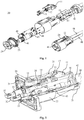
- Fig. 1 is a schematic illustration showing an electrical connector system comprising a first connector 20 and a CPA member 10.
- the upper illustration shows an exploded view and the lower illustration shows the parts in assembled condition.
- Exemplarily two power cables 40 are connected each to respective female contact terminals 43.
- These female contact terminals 43 are in assembled condition inserted into an isolation tube 48, which in assembled condition is partially inserted into a shielding sleeve 44.
- the figure shows a contact spring member 45 which upon assembly is inserted into the shielding sleeve 44, next to the isolation tube 48 onto a stripped portion of cable 40, so that it establishes an electrical connection between the cable shielding 46 and the shielding sleeve 44.
- a connector housing 22 which in assembled condition accommodates the described components.
- the housing 22 comprises a latching wing 25 whose function is described below in the context of Figs. 3A and 3B .
- the housing 22 can be closed from the cable side by a cover 21.
- the cover 21 presses two sealing rings 42 against a corresponding sealing surface (not visible in the figure) inside the connector housing 22.
- the sealing rings 42 are mounted to the cables 40 and in assembled condition they serve for sealing the first connector 20 against moisture from the cable side.
- a fastener 24 presses a further sealing member 23 against a corresponding sealing surface, so that in assembled condition the connector housing is also sealed against moisture from the opposite side.
- the CPA member 10 comprises a shorting clip 14, a support portion 13, a CPA sealing ring 12 and a CPA switch 11, the functions of which are described below.
- Fig. 2 shows the assembled first connector 20 in completely mated condition with a corresponding counter connector 30 (the counter connector 30 is shown in more detail in Fig. 5 ).
- the counter connector 30 is shown in more detail in Fig. 5 .
- the connectors 20 and 30 are cut away so that the interior components are visible.
- male contact terminals 32 of the counter connector 30 are inserted partially into the female contact terminals 43.
- the figure shows further two signal cables 15 of a signal circuit comprising contact ends 16.
- those cables are part of a signal circuit, i.e. a designated electrical circuit separate from the actual electrical power circuit established by cables 40, and further connected to e.g. electrical control units for activating, respectively deactivating, a power source.
- the contact ends 16 are in electrical contact through the shorting clip 14 (only the foreground contact end is fully visible in the figure).
- the shorting clip 14 is mounted on the support portion 13, which is further mounted on the CPA switch 11.
- the CPA switch 11 is inserted completely into its final position, whereby a locking surface 17 presses from below against an end of the latching arm 25, thereby blocking the same in the shown position.
- the function of the locking lever 25 is illustrated in more detail in figures 3A and 3B .
- Figs. 3A and 3B show detailed views of the assembly of Fig. 2 from a different perspective.
- the two figures illustrate the function of the CPA switch 11.
- the CPA member 10 In Fig. 3A , the CPA member 10 is not yet in its final position and therefore a gap between the locking lever 25 and the CPA switch 11 is visible.
- the skilled person can derive, that during assembly, when a counter connector housing 36 is inserted into the connector housing 22, the locking protrusion 35 presses the left part of the latching arm 25 up until it snaps down, when the locking clearance 26 fits over the locking protrusion 35. This movement of the latching arm 25 is only possible if the CPA member is not yet in its final position.
- the locking surface 17 of the CPA member 10 is arranged under the right part of the latching arm 25, so that it is no longer possible to press the right part of the latching arm and consequently, it is no longer possible to unlock the locking clearance 26 from the locking protrusion 35. From the figure one can derive that in this situation the counter connector housing 36 and the connector housing 22 are locked together by means of the fixing elements 26 and 35.
- Fig. 3A the CPA member 10 is not in its final position and the shorting clip is not in electrical contact with the contact ends 16.
- the shorting clip 14 is in contact with the contact ends 16 of the signal cables, thereby closing the signal circuit.
- the power source is activated only when the CPA is in its final closed position. Respectively, the power source will be deactivated only when the CPA will be opened. It will not be possible to un-mate the connector assembly while the power source is still activated.
- Figs. 3A and 3B one can further identify part of the CPA sealing 12 which is pressed between the support arm 13 and a surface of the connector housing 22 as well as one can see part of the sealing member 23 which is described above in the context of Fig. 1 .
- the signal cables 15 are mounted in the counter connector 30.
- these two cables 16 could as well be mounted in the first connector 20, still fulfilling the same function.
- Figure 4 shows a cross section of the interior parts of the connector arrangement of Fig. 2 , in particular a power cable 40, a male contact terminal 32 and a female contact terminal 43.
- the female contact terminal 43 is crimped on an end of the power cable 40.
- the male terminal 32 is partially inserted into the female contact terminal 43 which is mounted inside the isolation tube 48.
- the male contact terminal 32 is further mounted on an isolation member 33.
- the assembly of the two contact terminals is electromagnetically shielded by a shielding element 34 assigned to the male terminal and a shielding sleeve 44' assigned to the female terminal 43.
- the shielding sleeve 44' is similar to the above mentioned shielding sleeve 44 of Fig.
- the shielding sleeve 44' comprises a weakened portion 47 which serves to establish an electrical contact of the shielding sleeve 44' to the cable shielding 46 without the use of the above mentioned contact spring member 45.
- the electrical contact is established by contracting the weakened portion 47 of the shielding sleeve 44' inwardly until it contacts the cable shielding 46.
- said weakened portion 47 is realized by cutting slots into the shielding sleeve 44', which are oriented essentially parallel to the axis of the shielding sleeve 44'.
- the two electrically connected shielding members 34 and 44' which are due to the weakened portion 47 in electrical contact with the cable shielding 46, provide a shielding continuity for the cable shielding over the area in the connector system where the power cable 40 has to be stripped.
- Figure 5 shows another schematic illustration of the counter connector 30.
- the upper part of the figure shows not yet assembled single components of the counter connector 30 while the lower part of the figure shows its assembled condition from two different perspectives.
- the male contact terminals 32 are mounted inside isolation members 33, which are further mounted inside the shielding elements 34.
- the shielding elements 34 are then mounted inside the counter connector housing 36.
- the figure further shows the two signal cables 15 of the signal circuit, comprising the contact ends 16.
- the counter connector 30 comprises further a sealing o-ring 31.
- This sealing o-ring 31 is adapted to be pressed against a corresponding surface of a further component, on which the counter connector is mounted.
- FIG. 6 is a schematic drawing of an exemplary signal circuit.
- Two signal cables 15 enter an electrical acquisition unit 51.
- This acquisition unit 51 can detect whether the signal cables 15 are in electrical contact or not. If the contact state of the signal cables 15 is changed, the acquisition unit 51 sends a corresponding signal to the switching unit 53.
- This switching unit 53 reacts to the signal by opening or closing a switch incorporated exemplarily in one of the power cables 40. If closed, the power supply 52, which can be e.g. a battery of an electrical car, provides electrical power to the consumer 54, which could be the engine of the electrical car.
Description
- The present invention relates to electrical connector systems with additional features to improve the safety of the connection process, in particular with regard to electrical arcing.
- In high power applications as disclosed in
WO2008/109109 it is often necessary to switch off the electrical power source before two connectors which connect the power lines are mated or unmated. Indeed, it is safer not to leave power terminals supplied by high power while the connectors are unmated and consequently while the terminals may be exposed. It is also useful to prevent possible arcing when the connectors are close to each other but not yet fully mated as it inevitably occurs during mating and unmating. Such arcing may be dangerous for persons connecting or disconnecting the power line and it may additionally damage the connectors. Further, a high voltage peak which may be induced by the arcing can damage electrical devices which are connected to the power system. Therefore, commonly the high power has to be turned off manually before e.g. working on the high power system. This causes danger because the manual turning off can easily be forgotten, if e.g. untrained personal is involved or in the case of an accident where connections might have to be open rapidly. Therefore, solutions have been developed in the art providing ways for automatic turning off the power supply in the case that the power connectors are e.g. only in a pre-mated position. - An example of such a solution is described in
US 5,751,135 . This document proposes a charging connector device for electrical vehicles comprising a security mechanism to prevent dangerous arcing during the connection of the charging device and the power plug of the vehicle. First, when the charging device and the power plug are not yet fully mounted, a security lever presses a micro switch which turns off the main electrical power supply. Then, when the two members are correctly mated, the security lever releases the micro switch and the power is turned on. The same mechanism turns off the power during disconnecting the charging device and the power plug. - Further, connector position assurance (CPA) members are known in the art, to assure the correct mechanical coupling of two connectors with each other. Such members typically can have one or more of the following functions. For one they provide a mechanical secondary locking system for the connectors, where typically the CPA member can only be moved in the locking position when the electrical connectors are completely mated. In this locking position, the two connectors are mechanically locked together.
- Secondly, the CPA member serves as a visual checking means for the correct mounting. For this purpose, the CPA member is constructed so that it can be visually distinguished if the CPA member is moved fully into said locking position or not. With this function the technician can easily judge the state of the high power connection by simply looking at the CPA member.
- In addition, many high power applications require electromagnetic shielding of the electrical power lines. In particular in the case of hybrid or electrical vehicles it can be important to establish an electromagnetic shielding continuity from e.g. a power supply to the power dissipation device without interruptions. Such continuous electromagnetic shielding is problematic if the high power line includes connectors, since stripping is necessary for mounting of cables in connectors. Therefore, the electromagnetic cable shielding has to be bridged over the connectors. In the art commonly shielding bridges are mounted around the whole arrangement of terminals, power lines and housing parts, or the housing itself is made of conducting material or the housing includes a lining of conductive material to serve as shielding bridge. Unfortunately, in those cases it is necessary to provide openings in the shielding bridge to allow for the CPA member to function since it has to interact with parts of the connectors. This is a consequence of the requirement to provide compact connector systems, which for most applications is inevitable. Otherwise, more complicated CPA arrangements could be constructed around the connector assembly containing the shielding bridge, leading to rather large and expensive connector systems. This need for electromagnetic shielding combined with the need for a CPA member resulted in the problem to provide a new electrical connector system of the type disclosed in document
WO-A1-2011/124563 . - An aim of the present invention is to provide a new electrical connector system which solves or minimizes the above described problems and which, in assembled condition is sealed against moisture.
- It is another object of the present invention to provide an electrical connector system with an electrical security system guaranteeing the current flow through the connector only in the case of correct connector mating. It is a further object of the present invention to solve the above described problems with an inexpensive product which is simple to manufacture and assemble.
- These and other objects which become apparent upon reading the following description are solved by a connector system according to claim 1 and according to the claims dependent thereto.
- A new electrical connector system (in the following denoted as "the system") is provided which is in particular suited for the use in high power applications, such as a power of at least 1,5 kW. The new system comprises a first connector which is adapted to be mated to a corresponding counter connector, and the system is adapted to be connected to a signal circuit, which e.g. can be an electrical circuit. Further, the system comprises a movable connector position assurance (CPA) member. This CPA member can be moved to an end position only when the first connector is correctly mated to the counter connector. When placed in the end or final position, the CPA member interacts with the signal circuit, which thereby activates the electrical power source. The power source supplies the electrical power transmitted through the system. This interaction of the CPA member with the signal circuit may be e.g. a turning on or off of an electrical circuit, e.g. achieved by connecting or disconnecting two contacts by means of e.g. a shorting clip. The following activation of the electrical power source may e.g. be achieved directly, if the signal circuit is connected e.g. to a switch of the electrical power source or it may be achieved indirectly if the signal circuit is connected e.g. to suitable control units. In this case, the signal circuit could be connected to a control device which detects whether the signal circuit is switched on or off and reacts by sending a signal e.g. to a further electrical device, which reacts to this signal by enabling the electrical power. It is important to note that moving the CPA member out of the locked position results in the opposite interaction with the signal circuit, which in turn stops the activation of the power source. In other words, if the interaction is realized e.g. by connecting two contacts with a shorting clip as described above to close the signal circuit, moving the CPA member out of its locked position then results in the disconnection of said contacts, thereby opening the signal circuit. In this case the above mentioned control device now detects the opening of the signal circuit and reacts by sending a different signal which now tells the above mentioned further device to disable the electrical power. In summary, this interplay of CPA member, signal circuit and electrical power source guarantees that the main electrical power is transmitted through the system only, if the connectors are mated properly. Hereby a safety system is provided which prevents for instance the above described dangerous arcing which can occur if connectors of a high power line are approached to each other while the high power is turned on.
- The CPA member further locks the correctly mated position of the first connector and the counter connector mechanically. Hereby, the CPA member can e.g. provide a secondary locking system by e.g. constraining the primary locking system which serves for the correct mating of the two connectors in the first place. In this way, the connectors cannot be unmated if the CPA member is in its locked position. Thereby, an additional safety system is provided which hampers the disconnection of the two connectors when the main power is turned on. To physically disconnect the two connectors, the CPA member inevitably has to be moved out of its locked position, thereby automatically turning of the main electrical power. Then the two connectors can safely be unmated.
- The electrical connector system comprises a switching device which is adapted to switch the signal circuit and the CPA member is adapted to interact physically with this switching device. If the signal circuit is e.g. realized in form of an electrical circuit, a switching device could e.g. be an electrical switch. The CPA member can e.g. interact physically with this switch, by pressing the switch when moved in the locked position. The switch then turns on or off the electrical circuit, which results in the turning on of the electrical power as described above.
- In a different embodiment, the switching device could be realized in form of two electrical contacts which close the signal circuit when they are in contact. This could be realized e.g. by two metallic wires which are bent in a U-shaped form, the curves of the U-shaped wires pressed against each other by a spring force, thereby establishing an electrical connection closing the signal circuit. In this case, the CPA member could be an electrically isolated tongue, being movable in between the two wires, thereby disconnecting the electrical connection and opening the signal circuit. A further embodiment exemplarily is given by the same members used inversely. In this case the two U-shaped wires are initially disconnected. When the CPA member is placed in its end position, it moves one or both of the wires, thereby pressing the two into electrical contact and closing the signal circuit. In a further embodiment the switching device is realized in form of a variable resistor. In this case, the CPA member is adapted to interact with the variable resistor changing the resistance of the signal circuit. In an exemplary case of a closed electrical circuit connected to a secondary power supply, this resistance change results in a change of electrical current. In this embodiment it is possible, e.g. by lowering the resistance to achieve a higher current activating a switching mechanism. In another embodiment, the signal circuit comprises two electrical contacts and the CPA member comprises a shorting clip to connect the two electrical contacts when inserted correctly into its end position. Thus, the signal circuit is initially open and closed by the CPA member.
- The electrical connector system comprises at least one electromagnetically shielded conductor and at least one electromagnetic shielding element. The conductor may e.g. be an electrical power cable with an electromagnetic shielding, an insulating cable sheath and wire strands. The electromagnetic shielding element can e.g. continue the cable shielding over the system in assembled condition. The electromagnetic shielding element is realized essentially in form of a sleeve. The cable may e.g. be equipped with a contact terminal to be connected to another cable. The shielding sleeve can be mounted over the contact terminal e.g. inside a connector housing, while the CPA member and the signal circuit are mounted outside of said sleeve.
- The electromagnetic shielding sleeve is electrically connected to the cable shielding without the need for any separate contact spring members (as e.g. described in
EP 2 109 201 A2 ). This could e.g. be realized by crimping a portion of said shielding sleeve onto a stripped portion of the cable, where the cable shielding is exposed, thereby bringing these two members into electrical contact. - Said electromagnetic shielding sleeve provides an electromagnetic shielding of more than 40 dB, preferably of more than 55 dB, most preferably of more than 70 dB in the range of 10 kHz-5 MHz; and of more than 40 dB, preferably of more than 55 dB, most preferably of more than 65 dB in the range of 5 MHz-500 MHz. Further, the electrical connective system is further adapted to transmit currents of more than 10 A, preferably more than 25 A, and most preferably more than 50 A. In all the embodiments, it is preferred that the electrical connector system is adapted to safely transmit a power of more than 1,5 kW, preferably more than 10 kW, preferably more than 20 kW, yet more preferably more than 30 kW, even more preferably more than 40 kW and most preferred more than 50 kW. Obviously, the values for power and current depend on the intended application.
- According to the invention, the electrical connector system comprises sealing elements which are adapted to seal the electrical connector system against moisture in assembled condition. The electrical connector system comprises further a connector housing which is adapted to be assembled with a corresponding counter connector housing of the counter connector.
- This connector housing can be locked to the corresponding counter connector housing by means of a flexible latching arm. The CPA member comprises a locking surface which in mated condition prevents a movement of the latching arm, thereby blocking the position of the latching arm. Due to this locking mechanism - an example of which is shown in detail in the figures - the connector housings cannot be disconnected as long as the CPA member is in its end position.
- The invention is further directed to an electrical connector system for high power applications as described above, comprising the counter connector and the signal circuit.
- In the following the invention is described exemplarily with reference to the enclosed figures in which:
-
Fig. 1 is a schematic illustration of a connector system in accordance with the invention; -
Fig. 2 is a perspective and partially cut view showing a preferred embodiment of afirst connector 20 assembled with parts of acorresponding counter connector 30; -
Fig. 3A and 3B show details of the arrangement ofFig.2 ; -
Fig. 4 is a cross-sectional view showing a connection element of the electrical connector system; -
Fig. 5 illustrates the assembly of a preferred embodiment of thecorresponding counter connector 30; and -
Fig. 6 is a schematic illustration of an exemplary signal circuit. -
Fig. 1 is a schematic illustration showing an electrical connector system comprising afirst connector 20 and a CPA member 10. In the figure, the upper illustration shows an exploded view and the lower illustration shows the parts in assembled condition. Exemplarily twopower cables 40 are connected each to respectivefemale contact terminals 43. Thesefemale contact terminals 43 are in assembled condition inserted into anisolation tube 48, which in assembled condition is partially inserted into a shieldingsleeve 44. The figure shows acontact spring member 45 which upon assembly is inserted into the shieldingsleeve 44, next to theisolation tube 48 onto a stripped portion ofcable 40, so that it establishes an electrical connection between the cable shielding 46 and the shieldingsleeve 44. Thereby a shielding continuity over the connector assembly, respectively thefemale contact terminals 43 is achieved. Further, aconnector housing 22 is shown which in assembled condition accommodates the described components. Thehousing 22 comprises a latchingwing 25 whose function is described below in the context ofFigs. 3A and 3B . Thehousing 22 can be closed from the cable side by acover 21. Thereby, thecover 21 presses two sealingrings 42 against a corresponding sealing surface (not visible in the figure) inside theconnector housing 22. The sealing rings 42 are mounted to thecables 40 and in assembled condition they serve for sealing thefirst connector 20 against moisture from the cable side. Analogously, afastener 24 presses a further sealingmember 23 against a corresponding sealing surface, so that in assembled condition the connector housing is also sealed against moisture from the opposite side. - The CPA member 10 comprises a shorting
clip 14, asupport portion 13, aCPA sealing ring 12 and aCPA switch 11, the functions of which are described below. -
Fig. 2 shows the assembledfirst connector 20 in completely mated condition with a corresponding counter connector 30 (thecounter connector 30 is shown in more detail inFig. 5 ). For illustrative purposes in the figure parts of theconnectors male contact terminals 32 of thecounter connector 30 are inserted partially into thefemale contact terminals 43. - The figure shows further two
signal cables 15 of a signal circuit comprising contact ends 16. In an actual realization, those cables are part of a signal circuit, i.e. a designated electrical circuit separate from the actual electrical power circuit established bycables 40, and further connected to e.g. electrical control units for activating, respectively deactivating, a power source. In the figure, the contact ends 16 are in electrical contact through the shorting clip 14 (only the foreground contact end is fully visible in the figure). The shortingclip 14 is mounted on thesupport portion 13, which is further mounted on theCPA switch 11. In this figure, theCPA switch 11 is inserted completely into its final position, whereby a lockingsurface 17 presses from below against an end of the latchingarm 25, thereby blocking the same in the shown position. The function of the lockinglever 25 is illustrated in more detail infigures 3A and 3B . -
Figs. 3A and 3B show detailed views of the assembly ofFig. 2 from a different perspective. The two figures illustrate the function of theCPA switch 11. InFig. 3A , the CPA member 10 is not yet in its final position and therefore a gap between the lockinglever 25 and theCPA switch 11 is visible. Form the figure the skilled person can derive, that during assembly, when acounter connector housing 36 is inserted into theconnector housing 22, the lockingprotrusion 35 presses the left part of the latchingarm 25 up until it snaps down, when the lockingclearance 26 fits over the lockingprotrusion 35. This movement of the latchingarm 25 is only possible if the CPA member is not yet in its final position. When the CPA is in its final position, the lockingsurface 17 of the CPA member 10 is arranged under the right part of the latchingarm 25, so that it is no longer possible to press the right part of the latching arm and consequently, it is no longer possible to unlock the lockingclearance 26 from the lockingprotrusion 35. From the figure one can derive that in this situation thecounter connector housing 36 and theconnector housing 22 are locked together by means of the fixingelements - In
Fig. 3A the CPA member 10 is not in its final position and the shorting clip is not in electrical contact with the contact ends 16. As one can see, only when fully inserted, as shown inFig. 3B , the shortingclip 14 is in contact with the contact ends 16 of the signal cables, thereby closing the signal circuit. The power source is activated only when the CPA is in its final closed position. Respectively, the power source will be deactivated only when the CPA will be opened. It will not be possible to un-mate the connector assembly while the power source is still activated. InFigs. 3A and 3B one can further identify part of the CPA sealing 12 which is pressed between thesupport arm 13 and a surface of theconnector housing 22 as well as one can see part of the sealingmember 23 which is described above in the context ofFig. 1 . - In the shown embodiment of the connector system, the
signal cables 15 are mounted in thecounter connector 30. However, the skilled person will understand that these twocables 16 could as well be mounted in thefirst connector 20, still fulfilling the same function. -
Figure 4 shows a cross section of the interior parts of the connector arrangement ofFig. 2 , in particular apower cable 40, amale contact terminal 32 and afemale contact terminal 43. Thefemale contact terminal 43 is crimped on an end of thepower cable 40. Themale terminal 32 is partially inserted into thefemale contact terminal 43 which is mounted inside theisolation tube 48. Themale contact terminal 32 is further mounted on anisolation member 33. The assembly of the two contact terminals is electromagnetically shielded by a shieldingelement 34 assigned to the male terminal and a shielding sleeve 44' assigned to thefemale terminal 43. The shielding sleeve 44' is similar to the above mentioned shieldingsleeve 44 ofFig. 1 ; however, the shielding sleeve 44' comprises a weakenedportion 47 which serves to establish an electrical contact of the shielding sleeve 44' to the cable shielding 46 without the use of the above mentionedcontact spring member 45. In the embodiment ofFig. 4 , the electrical contact is established by contracting the weakenedportion 47 of the shielding sleeve 44' inwardly until it contacts the cable shielding 46. In the figure, one can see that said weakenedportion 47 is realized by cutting slots into the shielding sleeve 44', which are oriented essentially parallel to the axis of the shielding sleeve 44'. The two electrically connected shieldingmembers 34 and 44', which are due to the weakenedportion 47 in electrical contact with the cable shielding 46, provide a shielding continuity for the cable shielding over the area in the connector system where thepower cable 40 has to be stripped. -
Figure 5 shows another schematic illustration of thecounter connector 30. - The upper part of the figure shows not yet assembled single components of the
counter connector 30 while the lower part of the figure shows its assembled condition from two different perspectives. Themale contact terminals 32 are mounted insideisolation members 33, which are further mounted inside the shieldingelements 34. The shieldingelements 34 are then mounted inside thecounter connector housing 36. The figure further shows the twosignal cables 15 of the signal circuit, comprising the contact ends 16. Thecounter connector 30 comprises further a sealing o-ring 31. - This sealing o-
ring 31 is adapted to be pressed against a corresponding surface of a further component, on which the counter connector is mounted. -
Figure 6 is a schematic drawing of an exemplary signal circuit. Twosignal cables 15 enter anelectrical acquisition unit 51. Thisacquisition unit 51 can detect whether thesignal cables 15 are in electrical contact or not. If the contact state of thesignal cables 15 is changed, theacquisition unit 51 sends a corresponding signal to theswitching unit 53. This switchingunit 53 reacts to the signal by opening or closing a switch incorporated exemplarily in one of thepower cables 40. If closed, thepower supply 52, which can be e.g. a battery of an electrical car, provides electrical power to theconsumer 54, which could be the engine of the electrical car.
Claims (6)
- Electrical connector system in particular for high power applications involving an electrical power of at least 1,5 kW, the electrical connector system being adapted to be connected to a designated signal circuit for activating an electrical power source upon switching, the electrical connector system comprising:- a first connector (20) to be mated to a corresponding counter connector (30),- at least one electromagnetic shielding element (44) and at least one electromagnetically shielded conductor (40), the at least one electromagnetic shielding element (44) being adapted to establish a shielding continuity for the at least one electromagnetically shielded conductor (40) throughout the electrical connector system in assembled condition, and- a movable connector position assurance (CPA) member (10) assigned to the first connector (20),whereby an end position is not reachable if the first connector is incorrectly mated to the counter connector, whereby the CPA member interacts with the signal circuit if placed in said end position to activate the electrical power source, characterized in that the electrical connector system comprises sealing elements (12, 23, 42) adapted to seal the electrical connector system against moisture, the at least one electromagnetic shielding element (44) being completely located in the sealed area of the electrical connector system when the first connector and the counter-connector are mated.
- Electrical connector system according to claim 1, comprising a switching device (14, 16) adapted to switch the signal circuit, the CPA member being adapted to interact physically with this switching device (14, 16)
- Electrical connector system according to claim 2, wherein the switching device (14, 16) comprises one or more of the following:• a micro switch;• two electrical contacts integrated in the signal circuit, closing the signal circuit when in electrical contact with each other;• a variable resistor.
- Electrical connector system according to any one of the preceding claims, wherein it further comprises the counter connector (30) and comprises the signal circuit which comprises two electrical contacts (16), and wherein the CPA member comprises a shorting clip (14) adapted to connect the two electrical contacts (16), thereby turning on the signal circuit.
- Electrical connector system according to claim 1, wherein the at least one electromagnetic shielding element (44) is realized essentially in form of a sleeve, the CPA member (10) and the signal circuit being arranged outside of the at least one electromagnetic shielding sleeve (40).
- Electrical connector system according to claim 6, wherein the at least one electromagnetic shielding sleeve (44) is adapted to be electrically connected to the shielding (46) of the at least one electromagnetically shielded conductor (40) without the need for any separate contact spring members (45).
Applications Claiming Priority (2)
| Application Number | Priority Date | Filing Date | Title |
|---|---|---|---|
| IB2010001278 | 2010-04-09 | ||
| PCT/EP2011/055242 WO2011124563A1 (en) | 2010-04-09 | 2011-04-05 | Electrical connector system |
Publications (2)
| Publication Number | Publication Date |
|---|---|
| EP2556567A1 EP2556567A1 (en) | 2013-02-13 |
| EP2556567B1 true EP2556567B1 (en) | 2017-04-05 |
Family
ID=43927928
Family Applications (1)
| Application Number | Title | Priority Date | Filing Date |
|---|---|---|---|
| EP11711931.3A Not-in-force EP2556567B1 (en) | 2010-04-09 | 2011-04-05 | Electrical connector system |
Country Status (5)
| Country | Link |
|---|---|
| US (1) | US8827729B2 (en) |
| EP (1) | EP2556567B1 (en) |
| JP (1) | JP5826248B2 (en) |
| CN (1) | CN102834984B (en) |
| WO (1) | WO2011124563A1 (en) |
Families Citing this family (74)
| Publication number | Priority date | Publication date | Assignee | Title |
|---|---|---|---|---|
| US9496720B2 (en) | 2004-08-20 | 2016-11-15 | Midtronics, Inc. | System for automatically gathering battery information |
| US9588185B2 (en) | 2010-02-25 | 2017-03-07 | Keith S. Champlin | Method and apparatus for detecting cell deterioration in an electrochemical cell or battery |
| WO2011109343A2 (en) | 2010-03-03 | 2011-09-09 | Midtronics, Inc. | Monitor for front terminal batteries |
| KR20130030766A (en) | 2010-06-03 | 2013-03-27 | 미드트로닉스, 인크. | Battery pack maintenance for electric vehicles |
| US11740294B2 (en) | 2010-06-03 | 2023-08-29 | Midtronics, Inc. | High use battery pack maintenance |
| US10046649B2 (en) | 2012-06-28 | 2018-08-14 | Midtronics, Inc. | Hybrid and electric vehicle battery pack maintenance device |
| JP5686577B2 (en) * | 2010-11-15 | 2015-03-18 | 矢崎総業株式会社 | Connector unit |
| JP5751875B2 (en) * | 2011-03-22 | 2015-07-22 | 矢崎総業株式会社 | Shield connector |
| WO2012156373A1 (en) * | 2011-05-17 | 2012-11-22 | Fci Automotive Holding | Electrical connector assembly with a cpa element |
| WO2013070850A2 (en) | 2011-11-10 | 2013-05-16 | Midtronics, Inc. | Battery pack tester |
| DE102012100235B4 (en) | 2012-01-12 | 2015-12-24 | Phoenix Contact Gmbh & Co. Kg | Cable plug with covering device |
| US9425541B2 (en) * | 2012-04-05 | 2016-08-23 | Molex, Llc | High power electrical connector |
| US9851411B2 (en) | 2012-06-28 | 2017-12-26 | Keith S. Champlin | Suppressing HF cable oscillations during dynamic measurements of cells and batteries |
| US11325479B2 (en) | 2012-06-28 | 2022-05-10 | Midtronics, Inc. | Hybrid and electric vehicle battery maintenance device |
| US8926355B2 (en) * | 2012-06-29 | 2015-01-06 | Lear Corporation | Connector position assurance device for a connector assembly |
| EP2907201B1 (en) * | 2012-10-15 | 2022-06-15 | Aptiv Technologies Limited | Electrical connection system |
| DE202012011808U1 (en) * | 2012-12-10 | 2014-03-13 | Rosenberger Hochfrequenztechnik Gmbh & Co. Kg | connecting device |
| US9930592B2 (en) | 2013-02-19 | 2018-03-27 | Mimosa Networks, Inc. | Systems and methods for directing mobile device connectivity |
| US9179336B2 (en) | 2013-02-19 | 2015-11-03 | Mimosa Networks, Inc. | WiFi management interface for microwave radio and reset to factory defaults |
| US9130305B2 (en) * | 2013-03-06 | 2015-09-08 | Mimosa Networks, Inc. | Waterproof apparatus for cables and cable interfaces |
| WO2014138292A1 (en) | 2013-03-06 | 2014-09-12 | Mimosa Networks, Inc. | Enclosure for radio, parabolic dish antenna, and side lobe shields |
| US10742275B2 (en) | 2013-03-07 | 2020-08-11 | Mimosa Networks, Inc. | Quad-sector antenna using circular polarization |
| US9191081B2 (en) | 2013-03-08 | 2015-11-17 | Mimosa Networks, Inc. | System and method for dual-band backhaul radio |
| US9244100B2 (en) * | 2013-03-15 | 2016-01-26 | Midtronics, Inc. | Current clamp with jaw closure detection |
| US9295103B2 (en) | 2013-05-30 | 2016-03-22 | Mimosa Networks, Inc. | Wireless access points providing hybrid 802.11 and scheduled priority access communications |
| US10938110B2 (en) | 2013-06-28 | 2021-03-02 | Mimosa Networks, Inc. | Ellipticity reduction in circularly polarized array antennas |
| JP6289042B2 (en) * | 2013-11-13 | 2018-03-07 | タイコエレクトロニクスジャパン合同会社 | Connector with connector position assurance mechanism and connector fitting |
| US10843574B2 (en) | 2013-12-12 | 2020-11-24 | Midtronics, Inc. | Calibration and programming of in-vehicle battery sensors |
| EP2897229A1 (en) | 2014-01-16 | 2015-07-22 | Midtronics, Inc. | Battery clamp with endoskeleton design |
| US9001689B1 (en) | 2014-01-24 | 2015-04-07 | Mimosa Networks, Inc. | Channel optimization in half duplex communications systems |
| DE102014102197B4 (en) | 2014-02-20 | 2019-02-14 | Phoenix Contact E-Mobility Gmbh | Connector part with a locking element |
| US9780892B2 (en) | 2014-03-05 | 2017-10-03 | Mimosa Networks, Inc. | System and method for aligning a radio using an automated audio guide |
| US9998246B2 (en) | 2014-03-13 | 2018-06-12 | Mimosa Networks, Inc. | Simultaneous transmission on shared channel |
| US10473555B2 (en) | 2014-07-14 | 2019-11-12 | Midtronics, Inc. | Automotive maintenance system |
| US10958332B2 (en) | 2014-09-08 | 2021-03-23 | Mimosa Networks, Inc. | Wi-Fi hotspot repeater |
| USD752566S1 (en) | 2014-09-12 | 2016-03-29 | Mimosa Networks, Inc. | Wireless repeater |
| US10222397B2 (en) | 2014-09-26 | 2019-03-05 | Midtronics, Inc. | Cable connector for electronic battery tester |
| WO2016123075A1 (en) | 2015-01-26 | 2016-08-04 | Midtronics, Inc. | Alternator tester |
| DE102015113875A1 (en) * | 2015-08-21 | 2017-02-23 | Phoenix Contact E-Mobility Gmbh | Connector part with a locking element |
| US9966676B2 (en) | 2015-09-28 | 2018-05-08 | Midtronics, Inc. | Kelvin connector adapter for storage battery |
| WO2017123558A1 (en) | 2016-01-11 | 2017-07-20 | Mimosa Networks, Inc. | Printed circuit board mounted antenna and waveguide interface |
| US10574001B2 (en) | 2016-01-13 | 2020-02-25 | Molex, Llc | High power electrical connector |
| FR3046884B1 (en) * | 2016-01-20 | 2018-01-26 | Aptiv Technologies Limited | ELECTRICAL CONNECTION DEVICE AND METHOD FOR MOUNTING AN ELECTRICAL CONNECTION DEVICE |
| US10608353B2 (en) | 2016-06-28 | 2020-03-31 | Midtronics, Inc. | Battery clamp |
| CN107618458B (en) * | 2016-07-14 | 2021-10-22 | 矢崎(中国)投资有限公司 | Connector and internal signal circuit terminal |
| US11251539B2 (en) | 2016-07-29 | 2022-02-15 | Airspan Ip Holdco Llc | Multi-band access point antenna array |
| US10148034B2 (en) * | 2016-08-01 | 2018-12-04 | Te Connectivity Corporation | Arcless power connector |
| US10020613B2 (en) | 2016-08-01 | 2018-07-10 | Te Connectivity Corporation | Power terminal for arcless power connector |
| US11054480B2 (en) | 2016-10-25 | 2021-07-06 | Midtronics, Inc. | Electrical load for electronic battery tester and electronic battery tester including such electrical load |
| CN106785660A (en) * | 2016-12-23 | 2017-05-31 | 上海航天科工电器研究院有限公司 | A kind of high pressure arc extinguishing quick-lock connector |
| CN108075271B (en) * | 2016-12-30 | 2024-01-26 | 安波福中央电气(上海)有限公司 | High-energy electric connector |
| US10511074B2 (en) | 2018-01-05 | 2019-12-17 | Mimosa Networks, Inc. | Higher signal isolation solutions for printed circuit board mounted antenna and waveguide interface |
| US10355414B1 (en) | 2018-02-08 | 2019-07-16 | Delphi Technologies, Llc | Connector with a connector position assurance device |
| WO2019168800A1 (en) | 2018-03-02 | 2019-09-06 | Mimosa Networks, Inc. | Omni-directional orthogonally-polarized antenna system for mimo applications |
| US11183804B2 (en) * | 2018-07-23 | 2021-11-23 | J.S.T. Corporation | Connector system and electrical circuit for connector position assurance member |
| US11289821B2 (en) | 2018-09-11 | 2022-03-29 | Air Span Ip Holdco Llc | Sector antenna systems and methods for providing high gain and high side-lobe rejection |
| US10770825B2 (en) | 2018-10-24 | 2020-09-08 | Aptiv Technologies Limited | Electrical contact spring and electrical assembly including same |
| US11513160B2 (en) | 2018-11-29 | 2022-11-29 | Midtronics, Inc. | Vehicle battery maintenance device |
| DE102019103478A1 (en) * | 2019-02-12 | 2020-08-13 | Rema Lipprandt Gmbh & Co. Kg | Electrical charging connector |
| US11566972B2 (en) | 2019-07-31 | 2023-01-31 | Midtronics, Inc. | Tire tread gauge using visual indicator |
| US11545839B2 (en) | 2019-11-05 | 2023-01-03 | Midtronics, Inc. | System for charging a series of connected batteries |
| US11668779B2 (en) | 2019-11-11 | 2023-06-06 | Midtronics, Inc. | Hybrid and electric vehicle battery pack maintenance device |
| US11474153B2 (en) | 2019-11-12 | 2022-10-18 | Midtronics, Inc. | Battery pack maintenance system |
| CN111200223B (en) * | 2019-12-09 | 2021-05-18 | 中航光电科技股份有限公司 | A kind of interface unit |
| US11486930B2 (en) | 2020-01-23 | 2022-11-01 | Midtronics, Inc. | Electronic battery tester with battery clamp storage holsters |
| US11303078B2 (en) | 2020-03-04 | 2022-04-12 | Zf Cv Systems Global Gmbh | Electrical connector with enhanced data communication |
| US11594838B2 (en) * | 2020-04-28 | 2023-02-28 | Foxconn (Kunshan) Computer Connector Co., Ltd. | Connector assembly with connector position assurance |
| EP4176493A1 (en) * | 2020-07-01 | 2023-05-10 | CommScope Technologies LLC | Power cable connectors and assemblies |
| DE112021003303T5 (en) * | 2020-07-29 | 2023-05-25 | Eaton Intelligent Power Limited | ELECTRICAL CONNECTION SYSTEM WITH CYLINDRICAL CLAMP BODY |
| CN112310691B (en) * | 2020-09-24 | 2023-11-10 | 宁德时代新能源科技股份有限公司 | Position assurance device, connector assembly, battery and power utilization device |
| JP2022070624A (en) * | 2020-10-27 | 2022-05-13 | 住友電装株式会社 | Shield connection structure and connector |
| US20230115154A1 (en) * | 2021-10-11 | 2023-04-13 | Ford Global Technologies, Llc | Traction battery circuit interrupter assembly and interruption method |
| DE102022102252A1 (en) | 2022-02-01 | 2023-08-03 | Bayerische Motoren Werke Aktiengesellschaft | High-voltage plug connection device to ensure the correct electrical coupling of high-voltage components in an electrified motor vehicle |
| US20230291150A1 (en) * | 2022-03-09 | 2023-09-14 | Tyco Electronics (Shanghai) Co., Ltd. | Connector and Connector Assembly |
Family Cites Families (12)
| Publication number | Priority date | Publication date | Assignee | Title |
|---|---|---|---|---|
| JP2921640B2 (en) * | 1994-03-17 | 1999-07-19 | 矢崎総業株式会社 | Power supply connector |
| JP3135040B2 (en) | 1995-11-30 | 2001-02-13 | 矢崎総業株式会社 | Electric vehicle charging connector |
| JP3820355B2 (en) | 2001-05-18 | 2006-09-13 | 矢崎総業株式会社 | Power circuit breaker |
| US6964579B2 (en) * | 2003-06-06 | 2005-11-15 | Fci Americas Technology, Inc. | Position assured connector |
| DE102004057093B3 (en) * | 2004-11-25 | 2006-05-24 | Yazaki Europe Ltd., Hemel Hempstead | connector |
| WO2008109109A1 (en) | 2007-03-06 | 2008-09-12 | Tyco Electronics Corporation | High voltage shielded electrical connector assembly |
| US7404720B1 (en) * | 2007-03-29 | 2008-07-29 | Tesla Motors, Inc. | Electro mechanical connector for use in electrical applications |
| DE102008018205B4 (en) | 2008-04-10 | 2015-12-24 | Pflitsch Gmbh & Co. Kg | Device for electromagnetically sealed arrangement of a cable |
| JP5040800B2 (en) | 2008-05-14 | 2012-10-03 | 日立電線株式会社 | Connector for electrical connection |
| JP5040821B2 (en) * | 2008-06-09 | 2012-10-03 | 日立電線株式会社 | Connector for electrical connection |
| WO2010015889A1 (en) | 2008-08-04 | 2010-02-11 | Fci | Electrical connector assembly, an electrical device comprising the same and a method for mating the same |
| US8282411B2 (en) * | 2010-03-01 | 2012-10-09 | International Engine Intellectual Property Company, Llc. | Connector position assurance lock |
-
2011
- 2011-04-05 CN CN201180018306.4A patent/CN102834984B/en not_active Expired - Fee Related
- 2011-04-05 US US13/639,555 patent/US8827729B2/en active Active
- 2011-04-05 WO PCT/EP2011/055242 patent/WO2011124563A1/en active Application Filing
- 2011-04-05 EP EP11711931.3A patent/EP2556567B1/en not_active Not-in-force
- 2011-04-05 JP JP2013503082A patent/JP5826248B2/en not_active Expired - Fee Related
Non-Patent Citations (1)
| Title |
|---|
| None * |
Also Published As
| Publication number | Publication date |
|---|---|
| US8827729B2 (en) | 2014-09-09 |
| JP5826248B2 (en) | 2015-12-02 |
| CN102834984A (en) | 2012-12-19 |
| EP2556567A1 (en) | 2013-02-13 |
| WO2011124563A1 (en) | 2011-10-13 |
| CN102834984B (en) | 2015-09-30 |
| JP2013524454A (en) | 2013-06-17 |
| US20130078835A1 (en) | 2013-03-28 |
Similar Documents
| Publication | Publication Date | Title |
|---|---|---|
| EP2556567B1 (en) | Electrical connector system | |
| KR101910462B1 (en) | Safety system for high current applications | |
| EP1445839B1 (en) | System of preventing electric arcs in connectors that supply power charges | |
| CN107302147B (en) | Electric connector system | |
| CA2800118C (en) | Adapter coupling for bushing and arrestor | |
| CN108475889B (en) | High-power electric connector | |
| US20070161262A1 (en) | Detachable magnetic electrical connector | |
| US20180034200A1 (en) | Ferrule assembly for an electrical connector | |
| CA2979189A1 (en) | Power cable assembly having a circuit protection device | |
| CN109638553B (en) | Hot-line plugging electric connector for underwater cable incoming line | |
| US20070059973A1 (en) | Hot plug wire contact and connector assembly | |
| CN103682882A (en) | Connector connecting structure | |
| US5916002A (en) | Connecting system for electric conductors | |
| CN104521075A (en) | Interconnection assembly for vehicle devices and method of interconnection | |
| CN113328292A (en) | Connector with a locking member | |
| CN110600939B (en) | Power supply circuit breaker | |
| JPH04118877A (en) | Connection confirming device for connector | |
| CN110198861B (en) | Electrical connection device, electrical architecture, and electric or hybrid electric vehicle | |
| US11322883B1 (en) | High voltage direct current connector assembly or adapter with arc protection | |
| EP3389148B1 (en) | Electrical connector assembly | |
| CN220439959U (en) | Electrical connector and connector assembly | |
| CN211404911U (en) | High-voltage interlocking loop system, female connector and male connector for high-voltage interlocking loop system | |
| EP4054024A1 (en) | Passive detection of overheating in a power connector | |
| WO1996016424A1 (en) | A fuse arrangement |
Legal Events
| Date | Code | Title | Description |
|---|---|---|---|
| PUAI | Public reference made under article 153(3) epc to a published international application that has entered the european phase |
Free format text: ORIGINAL CODE: 0009012 |
|
| 17P | Request for examination filed |
Effective date: 20121109 |
|
| AK | Designated contracting states |
Kind code of ref document: A1 Designated state(s): AL AT BE BG CH CY CZ DE DK EE ES FI FR GB GR HR HU IE IS IT LI LT LU LV MC MK MT NL NO PL PT RO RS SE SI SK SM TR |
|
| DAX | Request for extension of the european patent (deleted) | ||
| RAP1 | Party data changed (applicant data changed or rights of an application transferred) |
Owner name: DELPHI INTERNATIONAL OPERATIONS LUXEMBOURG S.A R.L |
|
| GRAP | Despatch of communication of intention to grant a patent |
Free format text: ORIGINAL CODE: EPIDOSNIGR1 |
|
| INTG | Intention to grant announced |
Effective date: 20161212 |
|
| GRAS | Grant fee paid |
Free format text: ORIGINAL CODE: EPIDOSNIGR3 |
|
| GRAA | (expected) grant |
Free format text: ORIGINAL CODE: 0009210 |
|
| AK | Designated contracting states |
Kind code of ref document: B1 Designated state(s): AL AT BE BG CH CY CZ DE DK EE ES FI FR GB GR HR HU IE IS IT LI LT LU LV MC MK MT NL NO PL PT RO RS SE SI SK SM TR |
|
| REG | Reference to a national code |
Ref country code: GB Ref legal event code: FG4D |
|
| REG | Reference to a national code |
Ref country code: CH Ref legal event code: EP |
|
| REG | Reference to a national code |
Ref country code: AT Ref legal event code: REF Ref document number: 882628 Country of ref document: AT Kind code of ref document: T Effective date: 20170415 |
|
| REG | Reference to a national code |
Ref country code: FR Ref legal event code: PLFP Year of fee payment: 7 |
|
| REG | Reference to a national code |
Ref country code: IE Ref legal event code: FG4D |
|
| REG | Reference to a national code |
Ref country code: DE Ref legal event code: R096 Ref document number: 602011036642 Country of ref document: DE |
|
| REG | Reference to a national code |
Ref country code: NL Ref legal event code: MP Effective date: 20170405 |
|
| REG | Reference to a national code |
Ref country code: LT Ref legal event code: MG4D |
|
| REG | Reference to a national code |
Ref country code: AT Ref legal event code: MK05 Ref document number: 882628 Country of ref document: AT Kind code of ref document: T Effective date: 20170405 |
|
| PG25 | Lapsed in a contracting state [announced via postgrant information from national office to epo] |
Ref country code: NL Free format text: LAPSE BECAUSE OF FAILURE TO SUBMIT A TRANSLATION OF THE DESCRIPTION OR TO PAY THE FEE WITHIN THE PRESCRIBED TIME-LIMIT Effective date: 20170405 |
|
| PG25 | Lapsed in a contracting state [announced via postgrant information from national office to epo] |
Ref country code: HR Free format text: LAPSE BECAUSE OF FAILURE TO SUBMIT A TRANSLATION OF THE DESCRIPTION OR TO PAY THE FEE WITHIN THE PRESCRIBED TIME-LIMIT Effective date: 20170405 Ref country code: FI Free format text: LAPSE BECAUSE OF FAILURE TO SUBMIT A TRANSLATION OF THE DESCRIPTION OR TO PAY THE FEE WITHIN THE PRESCRIBED TIME-LIMIT Effective date: 20170405 Ref country code: ES Free format text: LAPSE BECAUSE OF FAILURE TO SUBMIT A TRANSLATION OF THE DESCRIPTION OR TO PAY THE FEE WITHIN THE PRESCRIBED TIME-LIMIT Effective date: 20170405 Ref country code: GR Free format text: LAPSE BECAUSE OF FAILURE TO SUBMIT A TRANSLATION OF THE DESCRIPTION OR TO PAY THE FEE WITHIN THE PRESCRIBED TIME-LIMIT Effective date: 20170706 Ref country code: LT Free format text: LAPSE BECAUSE OF FAILURE TO SUBMIT A TRANSLATION OF THE DESCRIPTION OR TO PAY THE FEE WITHIN THE PRESCRIBED TIME-LIMIT Effective date: 20170405 Ref country code: NO Free format text: LAPSE BECAUSE OF FAILURE TO SUBMIT A TRANSLATION OF THE DESCRIPTION OR TO PAY THE FEE WITHIN THE PRESCRIBED TIME-LIMIT Effective date: 20170705 Ref country code: AT Free format text: LAPSE BECAUSE OF FAILURE TO SUBMIT A TRANSLATION OF THE DESCRIPTION OR TO PAY THE FEE WITHIN THE PRESCRIBED TIME-LIMIT Effective date: 20170405 |
|
| PG25 | Lapsed in a contracting state [announced via postgrant information from national office to epo] |
Ref country code: RS Free format text: LAPSE BECAUSE OF FAILURE TO SUBMIT A TRANSLATION OF THE DESCRIPTION OR TO PAY THE FEE WITHIN THE PRESCRIBED TIME-LIMIT Effective date: 20170405 Ref country code: BG Free format text: LAPSE BECAUSE OF FAILURE TO SUBMIT A TRANSLATION OF THE DESCRIPTION OR TO PAY THE FEE WITHIN THE PRESCRIBED TIME-LIMIT Effective date: 20170705 Ref country code: SE Free format text: LAPSE BECAUSE OF FAILURE TO SUBMIT A TRANSLATION OF THE DESCRIPTION OR TO PAY THE FEE WITHIN THE PRESCRIBED TIME-LIMIT Effective date: 20170405 Ref country code: IS Free format text: LAPSE BECAUSE OF FAILURE TO SUBMIT A TRANSLATION OF THE DESCRIPTION OR TO PAY THE FEE WITHIN THE PRESCRIBED TIME-LIMIT Effective date: 20170805 Ref country code: PL Free format text: LAPSE BECAUSE OF FAILURE TO SUBMIT A TRANSLATION OF THE DESCRIPTION OR TO PAY THE FEE WITHIN THE PRESCRIBED TIME-LIMIT Effective date: 20170405 Ref country code: LV Free format text: LAPSE BECAUSE OF FAILURE TO SUBMIT A TRANSLATION OF THE DESCRIPTION OR TO PAY THE FEE WITHIN THE PRESCRIBED TIME-LIMIT Effective date: 20170405 |
|
| REG | Reference to a national code |
Ref country code: CH Ref legal event code: PL |
|
| REG | Reference to a national code |
Ref country code: DE Ref legal event code: R097 Ref document number: 602011036642 Country of ref document: DE |
|
| REG | Reference to a national code |
Ref country code: IE Ref legal event code: MM4A |
|
| PG25 | Lapsed in a contracting state [announced via postgrant information from national office to epo] |
Ref country code: SK Free format text: LAPSE BECAUSE OF FAILURE TO SUBMIT A TRANSLATION OF THE DESCRIPTION OR TO PAY THE FEE WITHIN THE PRESCRIBED TIME-LIMIT Effective date: 20170405 Ref country code: EE Free format text: LAPSE BECAUSE OF FAILURE TO SUBMIT A TRANSLATION OF THE DESCRIPTION OR TO PAY THE FEE WITHIN THE PRESCRIBED TIME-LIMIT Effective date: 20170405 Ref country code: MC Free format text: LAPSE BECAUSE OF FAILURE TO SUBMIT A TRANSLATION OF THE DESCRIPTION OR TO PAY THE FEE WITHIN THE PRESCRIBED TIME-LIMIT Effective date: 20170405 Ref country code: DK Free format text: LAPSE BECAUSE OF FAILURE TO SUBMIT A TRANSLATION OF THE DESCRIPTION OR TO PAY THE FEE WITHIN THE PRESCRIBED TIME-LIMIT Effective date: 20170405 Ref country code: RO Free format text: LAPSE BECAUSE OF FAILURE TO SUBMIT A TRANSLATION OF THE DESCRIPTION OR TO PAY THE FEE WITHIN THE PRESCRIBED TIME-LIMIT Effective date: 20170405 Ref country code: CZ Free format text: LAPSE BECAUSE OF FAILURE TO SUBMIT A TRANSLATION OF THE DESCRIPTION OR TO PAY THE FEE WITHIN THE PRESCRIBED TIME-LIMIT Effective date: 20170405 |
|
| PLBE | No opposition filed within time limit |
Free format text: ORIGINAL CODE: 0009261 |
|
| STAA | Information on the status of an ep patent application or granted ep patent |
Free format text: STATUS: NO OPPOSITION FILED WITHIN TIME LIMIT |
|
| PG25 | Lapsed in a contracting state [announced via postgrant information from national office to epo] |
Ref country code: LU Free format text: LAPSE BECAUSE OF NON-PAYMENT OF DUE FEES Effective date: 20170405 Ref country code: IT Free format text: LAPSE BECAUSE OF FAILURE TO SUBMIT A TRANSLATION OF THE DESCRIPTION OR TO PAY THE FEE WITHIN THE PRESCRIBED TIME-LIMIT Effective date: 20170405 Ref country code: LI Free format text: LAPSE BECAUSE OF NON-PAYMENT OF DUE FEES Effective date: 20170430 Ref country code: CH Free format text: LAPSE BECAUSE OF NON-PAYMENT OF DUE FEES Effective date: 20170430 Ref country code: SM Free format text: LAPSE BECAUSE OF FAILURE TO SUBMIT A TRANSLATION OF THE DESCRIPTION OR TO PAY THE FEE WITHIN THE PRESCRIBED TIME-LIMIT Effective date: 20170405 |
|
| 26N | No opposition filed |
Effective date: 20180108 |
|
| REG | Reference to a national code |
Ref country code: BE Ref legal event code: MM Effective date: 20170430 |
|
| REG | Reference to a national code |
Ref country code: FR Ref legal event code: PLFP Year of fee payment: 8 |
|
| PG25 | Lapsed in a contracting state [announced via postgrant information from national office to epo] |
Ref country code: IE Free format text: LAPSE BECAUSE OF NON-PAYMENT OF DUE FEES Effective date: 20170405 |
|
| PG25 | Lapsed in a contracting state [announced via postgrant information from national office to epo] |
Ref country code: SI Free format text: LAPSE BECAUSE OF FAILURE TO SUBMIT A TRANSLATION OF THE DESCRIPTION OR TO PAY THE FEE WITHIN THE PRESCRIBED TIME-LIMIT Effective date: 20170405 Ref country code: BE Free format text: LAPSE BECAUSE OF NON-PAYMENT OF DUE FEES Effective date: 20170430 |
|
| PG25 | Lapsed in a contracting state [announced via postgrant information from national office to epo] |
Ref country code: MT Free format text: LAPSE BECAUSE OF NON-PAYMENT OF DUE FEES Effective date: 20170405 |
|
| REG | Reference to a national code |
Ref country code: DE Ref legal event code: R081 Ref document number: 602011036642 Country of ref document: DE Owner name: APTIV TECHNOLOGIES LIMITED, BB Free format text: FORMER OWNER: DELPHI INTERNATIONAL OPERATIONS LUXEMBOURG S.A R.L., BASCHARAGE, LU |
|
| REG | Reference to a national code |
Ref country code: GB Ref legal event code: 732E Free format text: REGISTERED BETWEEN 20181213 AND 20181219 |
|
| PG25 | Lapsed in a contracting state [announced via postgrant information from national office to epo] |
Ref country code: HU Free format text: LAPSE BECAUSE OF FAILURE TO SUBMIT A TRANSLATION OF THE DESCRIPTION OR TO PAY THE FEE WITHIN THE PRESCRIBED TIME-LIMIT; INVALID AB INITIO Effective date: 20110405 |
|
| PG25 | Lapsed in a contracting state [announced via postgrant information from national office to epo] |
Ref country code: CY Free format text: LAPSE BECAUSE OF NON-PAYMENT OF DUE FEES Effective date: 20170405 |
|
| PG25 | Lapsed in a contracting state [announced via postgrant information from national office to epo] |
Ref country code: MK Free format text: LAPSE BECAUSE OF FAILURE TO SUBMIT A TRANSLATION OF THE DESCRIPTION OR TO PAY THE FEE WITHIN THE PRESCRIBED TIME-LIMIT Effective date: 20170405 |
|
| PG25 | Lapsed in a contracting state [announced via postgrant information from national office to epo] |
Ref country code: TR Free format text: LAPSE BECAUSE OF FAILURE TO SUBMIT A TRANSLATION OF THE DESCRIPTION OR TO PAY THE FEE WITHIN THE PRESCRIBED TIME-LIMIT Effective date: 20170405 |
|
| PG25 | Lapsed in a contracting state [announced via postgrant information from national office to epo] |
Ref country code: PT Free format text: LAPSE BECAUSE OF FAILURE TO SUBMIT A TRANSLATION OF THE DESCRIPTION OR TO PAY THE FEE WITHIN THE PRESCRIBED TIME-LIMIT Effective date: 20170405 |
|
| PG25 | Lapsed in a contracting state [announced via postgrant information from national office to epo] |
Ref country code: AL Free format text: LAPSE BECAUSE OF FAILURE TO SUBMIT A TRANSLATION OF THE DESCRIPTION OR TO PAY THE FEE WITHIN THE PRESCRIBED TIME-LIMIT Effective date: 20170405 |
|
| PGFP | Annual fee paid to national office [announced via postgrant information from national office to epo] |
Ref country code: GB Payment date: 20220421 Year of fee payment: 12 Ref country code: FR Payment date: 20220426 Year of fee payment: 12 Ref country code: DE Payment date: 20220420 Year of fee payment: 12 |
|
| REG | Reference to a national code |
Ref country code: DE Ref legal event code: R119 Ref document number: 602011036642 Country of ref document: DE |
|
| GBPC | Gb: european patent ceased through non-payment of renewal fee |
Effective date: 20230405 |
|
| PG25 | Lapsed in a contracting state [announced via postgrant information from national office to epo] |
Ref country code: GB Free format text: LAPSE BECAUSE OF NON-PAYMENT OF DUE FEES Effective date: 20230405 |
|
| PG25 | Lapsed in a contracting state [announced via postgrant information from national office to epo] |
Ref country code: GB Free format text: LAPSE BECAUSE OF NON-PAYMENT OF DUE FEES Effective date: 20230405 Ref country code: FR Free format text: LAPSE BECAUSE OF NON-PAYMENT OF DUE FEES Effective date: 20230430 Ref country code: DE Free format text: LAPSE BECAUSE OF NON-PAYMENT OF DUE FEES Effective date: 20231103 |