EP1284514A2 - Anode stream recirculation system for a fuel cell - Google Patents
Anode stream recirculation system for a fuel cell Download PDFInfo
- Publication number
- EP1284514A2 EP1284514A2 EP02003457A EP02003457A EP1284514A2 EP 1284514 A2 EP1284514 A2 EP 1284514A2 EP 02003457 A EP02003457 A EP 02003457A EP 02003457 A EP02003457 A EP 02003457A EP 1284514 A2 EP1284514 A2 EP 1284514A2
- Authority
- EP
- European Patent Office
- Prior art keywords
- fuel cell
- anode gas
- anode
- recirculation system
- switch
- Prior art date
- Legal status (The legal status is an assumption and is not a legal conclusion. Google has not performed a legal analysis and makes no representation as to the accuracy of the status listed.)
- Granted
Links
Images


Classifications
-
- H—ELECTRICITY
- H01—ELECTRIC ELEMENTS
- H01M—PROCESSES OR MEANS, e.g. BATTERIES, FOR THE DIRECT CONVERSION OF CHEMICAL ENERGY INTO ELECTRICAL ENERGY
- H01M8/00—Fuel cells; Manufacture thereof
- H01M8/04—Auxiliary arrangements, e.g. for control of pressure or for circulation of fluids
- H01M8/04082—Arrangements for control of reactant parameters, e.g. pressure or concentration
- H01M8/04089—Arrangements for control of reactant parameters, e.g. pressure or concentration of gaseous reactants
- H01M8/04119—Arrangements for control of reactant parameters, e.g. pressure or concentration of gaseous reactants with simultaneous supply or evacuation of electrolyte; Humidifying or dehumidifying
- H01M8/04126—Humidifying
-
- H—ELECTRICITY
- H01—ELECTRIC ELEMENTS
- H01M—PROCESSES OR MEANS, e.g. BATTERIES, FOR THE DIRECT CONVERSION OF CHEMICAL ENERGY INTO ELECTRICAL ENERGY
- H01M8/00—Fuel cells; Manufacture thereof
- H01M8/04—Auxiliary arrangements, e.g. for control of pressure or for circulation of fluids
- H01M8/04082—Arrangements for control of reactant parameters, e.g. pressure or concentration
- H01M8/04089—Arrangements for control of reactant parameters, e.g. pressure or concentration of gaseous reactants
- H01M8/04097—Arrangements for control of reactant parameters, e.g. pressure or concentration of gaseous reactants with recycling of the reactants
-
- Y—GENERAL TAGGING OF NEW TECHNOLOGICAL DEVELOPMENTS; GENERAL TAGGING OF CROSS-SECTIONAL TECHNOLOGIES SPANNING OVER SEVERAL SECTIONS OF THE IPC; TECHNICAL SUBJECTS COVERED BY FORMER USPC CROSS-REFERENCE ART COLLECTIONS [XRACs] AND DIGESTS
- Y02—TECHNOLOGIES OR APPLICATIONS FOR MITIGATION OR ADAPTATION AGAINST CLIMATE CHANGE
- Y02E—REDUCTION OF GREENHOUSE GAS [GHG] EMISSIONS, RELATED TO ENERGY GENERATION, TRANSMISSION OR DISTRIBUTION
- Y02E60/00—Enabling technologies; Technologies with a potential or indirect contribution to GHG emissions mitigation
- Y02E60/30—Hydrogen technology
- Y02E60/50—Fuel cells
Definitions
- This invention is related to an anode stream recirculation system for a fuel cell, in particular, an anode stream recirculation system used in a proton exchange membrane fuel cell, and most particularly, a hydrogen recirculation system utilized in a proton exchange membrane fuel cell.
- the present invention eliminates certain elements required in the conventional anode stream recirculation system for a fuel cell and, thus reduces the cost for manufacture of the components of the fuel cell. Furthermore, this invention lowers the electrical energy required for running the anode stream recirculation system so that the overall efficiency of electrical power generation for the fuel cell system can be promoted.
- the fuel cell is one of the most important and reasonably priced energy resources. Compared with traditional internal combustion engines, the fuel cell has many advantages such as high energy conversion efficiency, clean exhaust, low noise, and no consumption of traditional gasoline.
- a fuel cell is an electrical power generation device powered by the electrochemical reaction of hydrogen and oxygen.
- the reaction is a reverse reaction of the electrolysis of water, to convert the chemical energy into electrical energy.
- the basic structure of a fuel cell for example, a proton exchange membrane fuel cell, comprises a plurality of cell units.
- the structure of the cell unit generally illustrated in Fig. 1 comprises a proton exchange membrane (PEM) 10 at the middle, with the two sides thereof provided with a layer of catalyst 12, each of the two outsides of the catalyst 12 is further provided with a gas diffusion layer (GDL) 14.
- GDL gas diffusion layer
- An anode plate 16 and a cathode plate 18 are further provided at the outermost sides adjacent to the GDL 14.
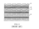
- a plurality of the above cell units are stacked and serially connected to provide sufficient power, as illustrated in Fig. 2. Therefore, two adjacent cell units can share a common polar plate 20, as illustrated in Fig. 3, which serves as the anode and the cathode for the two adjacent cell units, respectively. Accordingly, such a polar plate 20 is usually referred as a bipolar plate.
- a polar plate 20 is usually referred as a bipolar plate.
- the two sides of the bipolar plate 20 are provided with many groove type gas channels 22 for transporting the gases for reaction, such as hydrogen and air (to provide oxygen), as well as transporting the reactants, such as water droplets or vapor, out of the bipolar plate 20.
- One conventional gas supply system for use in a fuel cell comprises: a cathode gas supply system (such as an oxygen supply), and an anode circulation system (such as a hydrogen circulation system), as illustrated in Fig. 4.
- Atmospheric air may serve as a supply of the oxygen supply system 30, where air is filtered by a filter 32 and than pumped into the fuel cell 50 through a blower 34.
- Excessive air upon reaction within the fuel cell 50, is discharged through a water recuperator 36.
- the water recuperator 36 may recuperate the minute amount of water contained within the discharged air, where the water is then directed to a cooling system 38.
- the useless heat generated by the fuel cell 50 is also transmitted to the cooling system 38.
- the coolant used in the cooling system 38 then re-enters the fuel cell 50 to provide sufficient cooling thereto.
- the conventional anode circulation system includes: a hydrogen source 40 which regulates hydrogen input through a regulation valve 42; a hydrogen pump 44 being provided at the other end of the fuel cell 50 for discharging excessive hydrogen, upon reaction within the fuel cell, and for pumping the hydrogen source 40 into the fuel cell 50.
- the excessive hydrogen is discharged through a humidifier 46, such as a bubbler, for increasing the humidity of the excessive hydrogen, then flows back into the piping of the hydrogen supply to be mixed with fresh hydrogen, and then repeats the same circulation.
- the water within the humidifier 46 can be communicated with the water within the cooling system 38.
- the hydrogen within the bipolar plate of the fuel cell must have adequate humidity such that the hydrogen ions (H + ) after reaction can be carried through the PEM by the water vapor.
- the hydrogen ions then react with the oxygen at the other side of the PEM and the electrons provided from the outer circuit, to establish proton conduction.
- the humidity of the hydrogen is too low, the PEM will be dehydrated, thus, the electrical resistance of the fuel cell will increase and the voltage of the fuel cell will decrease, which will result in the working life of the fuel cell being significantly shortened.
- the channels for transporting the gases within the bipolar plate may be clogged by water droplets, which will stop the reaction of gases within the fuel cell and the performance of the fuel cell will be seriously impaired. Accordingly, in the anode stream recirculation system, a humidifier to adjust the humidity of the hydrogen is generally required.
- a primary objective of this invention is to improve the conventional anode stream recirculation system by detecting the pressure of the excessive hydrogen discharged from the fuel cell to determine the open/close of the hydrogen source. Therefore, the conventional hydrogen pump may be eliminated and the parasitic loss of electrical energy of the fuel cell itself can be reduced and the overall efficiency of electrical power generation by the fuel cell system can be promoted.
- a further objective of this invention is to automatically clear out the gas channels of the bipolar plates within the fuel cell by the pressure pulses introduced from intermittently open/close of the hydrogen source so that no water droplet will stay within the gas channels to impair the power generation efficiency of the fuel cell.
- a further objective of this invention is to simplify the manufacturing process and to lower the production cost of the fuel cell by improving the design of the humidifier used in the anode stream recirculation system.
- the primary technical contents of this invention are related to an anode stream recirculation system for a fuel cell.
- the fuel cell includes an anode gas input and an anode gas output.
- the anode stream recirculation system comprises: an anode gas supply providing the anode gas required for reaction of the fuel cell; a switch connected with the anode gas supply to control the open/close of the anode gas supply; a regulating device with one end thereof being connected with the switch and the other end thereof being connected with the anode gas input of the fuel cell, to control the amount of supplied anode gas; a sensor connected with both the anode gas output of the fuel cell so as to detect the amount of the anode gas discharged from the fuel cell after reaction, the sensor also connected with the switch so as to control the open/close of the switch; and a humidifier connected between the anode gas output and anode gas input of the fuel cell, to adjust the humidity of the discharged anode gas; the discharged anode gas after the adjustment of the
- This invention is related to an anode stream recirculation system for a fuel cell, in particular, a hydrogen recirculation system utilized in a proton exchange membrane (PEM) fuel cell.
- PEM proton exchange membrane
- One preferred embodiment of this invention is substantially shown in Fig. 5, which includes an anode gas supply 60 to provide the anode gas required for the reaction proceeded in the fuel cell 80.
- the anode gas is hydrogen.
- the anode gas flows through a switch 62 and a regulating device 64 before entering fuel cell 80 through an anode gas input 82.
- the switch 62 can be a solenoid valve which is used to control the open/close of the gas flow in the piping and to determine whether fresh anode gas should be released from the anode gas supply 60.
- the regulating device 64 may be a regulation valve, for example, to adjust the amount of the anode gas flowing therethrough. Generally, the regulating device is set to provide the flowing amount of the anode gas higher than the required Stoichiometric amount for a specific electrical power generation of the fuel cell so as to ensure that the electro-chemical reaction takes place entirely within the fuel cell 80.
- the fuel cell 80 also has an anode gas output 84.
- the anode stream recirculation system further comprises a sensor 66, such as a pressure switch in this preferred embodiment, somewhere after the anode gas output 84 along the anode gas output piping.
- the sensor 66 is used to detect the pressure or the amount of the anode gas discharged from the fuel cell 80.
- the sensor 66 is electrically connected with the switch 62.
- the sensor 66 can be used to switch on/off the switch 62 according to the pressure of the discharged anode gas.
- This invention further comprises a humidifier 70 which is installed along the anode gas output piping after the fuel cell 80 for adjusting the humidity of the discharged anode gas.
- the discharged anode gas after the adjustment of the humidity thereof is redirected to the anode gas input piping and then into the fuel cell 80 to form an anode gas recirculation.
- this discharged anode gas can also be mixed in the piping with the fresh anode gas which is controlled and released from the anode gas supply 60 that passes through the switch 62 and the regulating device 64.
- the sensor 66 measures the pressure of the anode gas discharged from the fuel cell 80.
- a first predetermined value such as a gauge pressure substantially higher than 10 psi
- the sensor 66 transmits a signal to switch off the switch 62.
- a second predetermined value such as a gauge pressure substantially lower than 2 psi
- the sensor 66 transmits another signal to switch on the switch 62.
- the regulating device 64 controls the pressure of the anode gas out of the anode gas supply 60 into the fuel cell 80 to a value approximately the same as the first predetermined value, such as 10 psi in this preferred embodiment.
- the switch 62 is opened so that the anode gas can be transported into the fuel cell 80. If the sensor 66 detects that the pressure of the anode gas reaches the first predetermined value, the sensor 66 transmits a control signal to the switch 62 which is thereby switched off. At this time, no more fresh anode gas is supplied.
- the flow rate of the anode gas is generally set at a value higher than the required Stoichiometric amount for a specific electrical power generation of the fuel cell 80 so as to ensure that the electrochemical reaction takes place completely within the fuel cell 80.
- Fig. 6 schematically illustrates the pressure of the anode gas within the fuel cell 80 varying with time according to the preferred embodiment of this invention.
- this invention can provide another advantage. That is, every time the switch 62 is opened, the anode gas with significantly higher pressure will thrust into the whole system, especially into the fuel cell 80. As a result, any water droplet condensed from the reaction of the fuel cell 80 or any undesired particle existing within the gas channels 22 of the bipolar plate 20 will be shattered and/or expelled out of the gas channels 22 by such intermittent high-pressure thrust gas.
- this invention also provides a function of intermittently and automatically clearing out the gas channels within the fuel cell.
- the humidifier 70 comprises a housing 72 containing a suitable amount of water 74 therein.
- a plurality of hydrophilic sheets 76 such as sponge or other articles with similar properties, are provided within the housing 72 and each of the hydrophilic sheets 76 is partially immersed within the water 74.
- the discharged excessive anode gas from the fuel cell 80 is directed into the humidifier 70 below the water level therein, the gas will then float out of the water 74 as bubbles, pass through the saturated hydrophilic sheets 76, and then be directed out of the housing 72 at the other end thereof.
- the humidity of the recirculated anode gas can be easily controlled by this humidifier 70.
- the above humidifier 70 of this invention involves more simplified construction and the manufacturing cost thereof is obviously much cheaper. Moreover, such a humidifier 70 does not consume any electrical power during operation and thus, the parasitic loss of electrical energy of the fuel cell itself is further reduced. Nevertheless, the conventional bubbler or steam generator may still be applied in the present anode stream recirculation system according to this invention to achieve the desired function or object. Finally, to ensure that the gas within the piping of the anode stream recirculation system can be directed to the designed direction, a check valve 78 may be provided on both side of the humidifier 70 at some appropriate positions, as illustrated in Fig. 5.
Landscapes
- Life Sciences & Earth Sciences (AREA)
- Sustainable Development (AREA)
- Engineering & Computer Science (AREA)
- Manufacturing & Machinery (AREA)
- Sustainable Energy (AREA)
- Chemical & Material Sciences (AREA)
- Chemical Kinetics & Catalysis (AREA)
- Electrochemistry (AREA)
- General Chemical & Material Sciences (AREA)
- Fuel Cell (AREA)
Abstract
Description
- 10
- proton exchange membrane
- 12
- catalyst
- 14
- gas diffusion layer
- 16
- anode plate
- 18
- cathode plate
- 20
- bipolar plate
- 22
- gas channels
- 30
- oxygen supply system
- 32
- filter
- 34
- blower
- 36
- water recuperator
- 38
- cooling system
- 40
- hydrogen source
- 42
- regulation valve
- 44
- hydrogen pump
- 46
- humidifier
- 50
- fuel cell
- 60
- anode gas supply
- 62
- switch
- 64
- regulating device
- 66
- sensor
- 70
- humidifier
- 72
- housing
- 74
- water
- 76
- hydrophilic sheets
- 78
- check valves
- 80
- fuel cell
- 82
- anode gas input
- 84
- anode gas output
Claims (10)
- An anode stream recirculation system for a fuel cell, the fuel cell including an anode gas input and an anode gas output, the anode stream recirculation system comprising:an anode gas supply, providing the anode gas required for reaction of the fuel cell;a switch connected with the anode gas supply;a regulating device connected between the switch and the anode gas input of the fuel cell;a sensor connected with both the anode gas output of the fuel cell and the switch; anda humidifier connected between the anode gas output and anode gas input of the fuel cell, thereby forming an anode gas recirculation.
- The anode stream recirculation system for a fuel cell according to Claim 1, wherein the anode gas is hydrogen.
- The anode stream recirculation system for a fuel cell according to Claim 1, wherein the switch is an electromagnetic valve.
- The anode stream recirculation system for a fuel cell according to Claim 1, wherein the sensor detects pressure of the anode gas discharged from the fuel cell, when the pressure increases to a first predetermined value, the sensor transmits a signal to switch off the switch; when the pressure decreases to a second predetermined value which is lower than the first predetermined value, the sensor transmits another signal to activate the switch.
- The anode stream recirculation system for a fuel cell according to Claim 1, wherein the humidifier comprises a housing containing a suitable amount of water and a plurality of hydrophilic sheets provided therein with each of the sheets being partially immersed within the water.
- The anode stream recirculation system for a fuel cell according to Claim 1, wherein the humidifier is a bubbler.
- The anode stream recirculation system for a fuel cell according to Claim 1, wherein the humidifier is a steam generator.
- The anode stream recirculation system for a fuel cell according to Claim 1, further comprising two check valves with one provided between the anode gas input of the fuel cell and the humidifier, and the other provided between the anode gas output of the fuel cell and the humidifier.
- The anode stream recirculation system for a fuel cell according to Claim 4, wherein the regulating device controls the pressure of the anode gas out of the anode gas supply into the fuel cell to a value substantially equal to the first predetermined value.
- The anode stream recirculation system for a fuel cell according to Claim 4, wherein the first predetermined value is set to be a gauge pressure substantially higher than 10 psi, and the second predetermined value is set to be a gauge pressure substantially lower than 2 psi.
Applications Claiming Priority (2)
| Application Number | Priority Date | Filing Date | Title |
|---|---|---|---|
| CNB011242213A CN1291516C (en) | 2001-08-16 | 2001-08-16 | Anode gas circulation system for fuel cells |
| CN01124221 | 2001-08-16 |
Publications (3)
| Publication Number | Publication Date |
|---|---|
| EP1284514A2 true EP1284514A2 (en) | 2003-02-19 |
| EP1284514A3 EP1284514A3 (en) | 2007-01-24 |
| EP1284514B1 EP1284514B1 (en) | 2010-05-26 |
Family
ID=4665589
Family Applications (1)
| Application Number | Title | Priority Date | Filing Date |
|---|---|---|---|
| EP02003457A Expired - Lifetime EP1284514B1 (en) | 2001-08-16 | 2002-02-14 | Anode stream recirculation system for a fuel cell |
Country Status (4)
| Country | Link |
|---|---|
| EP (1) | EP1284514B1 (en) |
| CN (1) | CN1291516C (en) |
| AT (1) | ATE469445T1 (en) |
| DE (1) | DE60236486D1 (en) |
Cited By (3)
| Publication number | Priority date | Publication date | Assignee | Title |
|---|---|---|---|---|
| WO2003105259A3 (en) * | 2002-06-10 | 2005-04-21 | Hewlett Packard Development Co | Fuel cell reactant supply |
| GB2442252A (en) * | 2006-09-27 | 2008-04-02 | Intelligent Energy Ltd | Low Temperature operation of open fuel cell stacks using air circulation |
| CN110620249A (en) * | 2018-12-24 | 2019-12-27 | 谷夫科技(上海)有限公司 | Fuel cell power generation system |
Families Citing this family (12)
| Publication number | Priority date | Publication date | Assignee | Title |
|---|---|---|---|---|
| JP4617675B2 (en) * | 2004-01-13 | 2011-01-26 | トヨタ自動車株式会社 | Fuel cell system |
| WO2006012953A2 (en) * | 2004-07-20 | 2006-02-09 | Conception Et Developpement Michelin S.A. | Control of the polymer humidifying membrane of a fuel cell |
| CN100502093C (en) * | 2005-08-26 | 2009-06-17 | 鸿富锦精密工业(深圳)有限公司 | Portable fuel battery |
| JP5082220B2 (en) * | 2005-10-05 | 2012-11-28 | トヨタ自動車株式会社 | Fuel cell system |
| JP5103998B2 (en) * | 2007-04-12 | 2012-12-19 | トヨタ自動車株式会社 | Fuel cell system |
| US9356304B2 (en) * | 2008-01-11 | 2016-05-31 | GM Global Technology Operations LLC | Anode recirculation pump control strategy |
| US8748051B2 (en) * | 2010-03-17 | 2014-06-10 | GM Global Technology Operations LLC | Adaptive loading of a fuel cell |
| CN102403525B (en) * | 2010-09-16 | 2016-02-03 | 流体公司 | Electrochemical cell system with progressive oxygen evolution electrode/fuel electrode |
| CN104157890A (en) * | 2014-08-18 | 2014-11-19 | 芜湖国氢能源股份有限公司 | Hydrogen fuel cell hot water utilization system |
| CN115249825A (en) * | 2021-04-25 | 2022-10-28 | 罗伯特·博世有限公司 | Humidification system and control method thereof, storage medium and fuel cell system |
| CN113285095B (en) * | 2021-07-21 | 2021-11-19 | 潍柴巴拉德氢能科技有限公司 | Hydrogen humidifying device |
| CN114024006A (en) * | 2021-12-06 | 2022-02-08 | 中国科学院大连化学物理研究所 | Fuel cell durability test platform |
Family Cites Families (4)
| Publication number | Priority date | Publication date | Assignee | Title |
|---|---|---|---|---|
| BE636538A (en) * | 1962-08-27 | |||
| JPH0831324B2 (en) * | 1985-06-27 | 1996-03-27 | 株式会社東芝 | Fuel cell power generation system Fuel system recirculation device |
| JP3448076B2 (en) * | 1993-03-04 | 2003-09-16 | 三菱重工業株式会社 | Operating method of solid polymer electrolyte fuel cell power generation system |
| JPH09180743A (en) * | 1995-12-22 | 1997-07-11 | Fuji Electric Co Ltd | Polymer electrolyte fuel cell |
-
2001
- 2001-08-16 CN CNB011242213A patent/CN1291516C/en not_active Expired - Fee Related
-
2002
- 2002-02-14 DE DE60236486T patent/DE60236486D1/en not_active Expired - Lifetime
- 2002-02-14 EP EP02003457A patent/EP1284514B1/en not_active Expired - Lifetime
- 2002-02-14 AT AT02003457T patent/ATE469445T1/en not_active IP Right Cessation
Cited By (6)
| Publication number | Priority date | Publication date | Assignee | Title |
|---|---|---|---|---|
| WO2003105259A3 (en) * | 2002-06-10 | 2005-04-21 | Hewlett Packard Development Co | Fuel cell reactant supply |
| US7122257B2 (en) | 2002-06-10 | 2006-10-17 | Hewlett-Packard Development Company, Lp. | Fuel cell reactant supply |
| GB2442252A (en) * | 2006-09-27 | 2008-04-02 | Intelligent Energy Ltd | Low Temperature operation of open fuel cell stacks using air circulation |
| GB2442252B (en) * | 2006-09-27 | 2010-10-27 | Intelligent Energy Ltd | Low temperature operation of open cathode fuel cell stacks using air recirculation |
| CN110620249A (en) * | 2018-12-24 | 2019-12-27 | 谷夫科技(上海)有限公司 | Fuel cell power generation system |
| CN110620249B (en) * | 2018-12-24 | 2020-09-18 | 谷夫科技(上海)有限公司 | Fuel cell power generation system |
Also Published As
| Publication number | Publication date |
|---|---|
| CN1291516C (en) | 2006-12-20 |
| EP1284514A3 (en) | 2007-01-24 |
| ATE469445T1 (en) | 2010-06-15 |
| EP1284514B1 (en) | 2010-05-26 |
| CN1405912A (en) | 2003-03-26 |
| DE60236486D1 (en) | 2010-07-08 |
Similar Documents
| Publication | Publication Date | Title |
|---|---|---|
| EP1284514B1 (en) | Anode stream recirculation system for a fuel cell | |
| US7008717B2 (en) | Diaphragm pump and anode stream recirculation system using such pump for a fuel cell | |
| US5976722A (en) | Process for operating a fuel cell installation and fuel cell installation for carrying out the process | |
| US6692852B2 (en) | Generating system for a fuel cell, and heat waste recirculating and cooling system of said generating system | |
| CA2389197C (en) | Fuel cell and method of operating same | |
| US7354670B2 (en) | Fuel cell with fuel gas adjustment mechanism | |
| US6699610B2 (en) | Anode stream recirculation system for a fuel cell | |
| CN112635793A (en) | Double-stack double-circulation fuel cell system | |
| US6623882B2 (en) | Bipolar plate for a fuel cell | |
| EP1284515A2 (en) | Generating system for a fuel cell, and heat waste recirculating and cooling system of said generating system | |
| CN112701323A (en) | Fuel cell injection device with proportional valve | |
| US7090941B2 (en) | Fuel cell stack and a method of supplying reactant gases to the fuel cell stack | |
| EP1288498B1 (en) | Diaphragm pump for a fuel cell | |
| CN1280936C (en) | Fuel cell system of proton exchange membrane with air being circulated partially | |
| KR100448692B1 (en) | Fuel feed system for fuel cell | |
| EP1284511A2 (en) | Bipolar plate for a fuel cell | |
| CN114709450B (en) | Air system of fuel cell and vehicle | |
| KR20030078973A (en) | Fuel cell system | |
| JP2005196984A (en) | Fuel cell system | |
| CN119340423A (en) | A marine fuel cell system with desalination and humidification functions | |
| KR20030078975A (en) | Fuel supplying device for fuel cell system | |
| KR20030078974A (en) | Fuel supplying device for fuel cell system | |
| CN100456541C (en) | Liquid Fuel Cell System | |
| CN118431504A (en) | Fuel cell system and method of operating the same | |
| CN121282245A (en) | Self-adaptive air-cooled hydrogen fuel cell system for gas-water-heat collaborative management and control method |
Legal Events
| Date | Code | Title | Description |
|---|---|---|---|
| PUAI | Public reference made under article 153(3) epc to a published international application that has entered the european phase |
Free format text: ORIGINAL CODE: 0009012 |
|
| AK | Designated contracting states |
Designated state(s): AT BE CH CY DE DK ES FI FR GB GR IE IT LI LU MC NL PT SE TR |
|
| AX | Request for extension of the european patent |
Extension state: AL LT LV MK RO SI |
|
| PUAL | Search report despatched |
Free format text: ORIGINAL CODE: 0009013 |
|
| AK | Designated contracting states |
Kind code of ref document: A3 Designated state(s): AT BE CH CY DE DK ES FI FR GB GR IE IT LI LU MC NL PT SE TR |
|
| AX | Request for extension of the european patent |
Extension state: AL LT LV MK RO SI |
|
| 17P | Request for examination filed |
Effective date: 20070628 |
|
| AKX | Designation fees paid |
Designated state(s): AT BE CH CY DE DK ES FI FR GB GR IE IT LI LU MC NL PT SE TR |
|
| 17Q | First examination report despatched |
Effective date: 20080911 |
|
| GRAP | Despatch of communication of intention to grant a patent |
Free format text: ORIGINAL CODE: EPIDOSNIGR1 |
|
| RIN1 | Information on inventor provided before grant (corrected) |
Inventor name: JEFFERSON, YANG YS,ASIA PACIFIC FUEL CELL TECH. LT |
|
| GRAS | Grant fee paid |
Free format text: ORIGINAL CODE: EPIDOSNIGR3 |
|
| GRAA | (expected) grant |
Free format text: ORIGINAL CODE: 0009210 |
|
| AK | Designated contracting states |
Kind code of ref document: B1 Designated state(s): AT BE CH CY DE DK ES FI FR GB GR IE IT LI LU MC NL PT SE TR |
|
| REG | Reference to a national code |
Ref country code: GB Ref legal event code: FG4D |
|
| REG | Reference to a national code |
Ref country code: CH Ref legal event code: EP |
|
| REG | Reference to a national code |
Ref country code: IE Ref legal event code: FG4D |
|
| REF | Corresponds to: |
Ref document number: 60236486 Country of ref document: DE Date of ref document: 20100708 Kind code of ref document: P |
|
| REG | Reference to a national code |
Ref country code: NL Ref legal event code: VDEP Effective date: 20100526 |
|
| PG25 | Lapsed in a contracting state [announced via postgrant information from national office to epo] |
Ref country code: SE Free format text: LAPSE BECAUSE OF FAILURE TO SUBMIT A TRANSLATION OF THE DESCRIPTION OR TO PAY THE FEE WITHIN THE PRESCRIBED TIME-LIMIT Effective date: 20100526 |
|
| PG25 | Lapsed in a contracting state [announced via postgrant information from national office to epo] |
Ref country code: FI Free format text: LAPSE BECAUSE OF FAILURE TO SUBMIT A TRANSLATION OF THE DESCRIPTION OR TO PAY THE FEE WITHIN THE PRESCRIBED TIME-LIMIT Effective date: 20100526 Ref country code: AT Free format text: LAPSE BECAUSE OF FAILURE TO SUBMIT A TRANSLATION OF THE DESCRIPTION OR TO PAY THE FEE WITHIN THE PRESCRIBED TIME-LIMIT Effective date: 20100526 |
|
| PG25 | Lapsed in a contracting state [announced via postgrant information from national office to epo] |
Ref country code: GR Free format text: LAPSE BECAUSE OF FAILURE TO SUBMIT A TRANSLATION OF THE DESCRIPTION OR TO PAY THE FEE WITHIN THE PRESCRIBED TIME-LIMIT Effective date: 20100827 Ref country code: CY Free format text: LAPSE BECAUSE OF FAILURE TO SUBMIT A TRANSLATION OF THE DESCRIPTION OR TO PAY THE FEE WITHIN THE PRESCRIBED TIME-LIMIT Effective date: 20100526 |
|
| PG25 | Lapsed in a contracting state [announced via postgrant information from national office to epo] |
Ref country code: PT Free format text: LAPSE BECAUSE OF FAILURE TO SUBMIT A TRANSLATION OF THE DESCRIPTION OR TO PAY THE FEE WITHIN THE PRESCRIBED TIME-LIMIT Effective date: 20100927 Ref country code: DK Free format text: LAPSE BECAUSE OF FAILURE TO SUBMIT A TRANSLATION OF THE DESCRIPTION OR TO PAY THE FEE WITHIN THE PRESCRIBED TIME-LIMIT Effective date: 20100526 Ref country code: NL Free format text: LAPSE BECAUSE OF FAILURE TO SUBMIT A TRANSLATION OF THE DESCRIPTION OR TO PAY THE FEE WITHIN THE PRESCRIBED TIME-LIMIT Effective date: 20100526 |
|
| PG25 | Lapsed in a contracting state [announced via postgrant information from national office to epo] |
Ref country code: BE Free format text: LAPSE BECAUSE OF FAILURE TO SUBMIT A TRANSLATION OF THE DESCRIPTION OR TO PAY THE FEE WITHIN THE PRESCRIBED TIME-LIMIT Effective date: 20100526 |
|
| PG25 | Lapsed in a contracting state [announced via postgrant information from national office to epo] |
Ref country code: IT Free format text: LAPSE BECAUSE OF FAILURE TO SUBMIT A TRANSLATION OF THE DESCRIPTION OR TO PAY THE FEE WITHIN THE PRESCRIBED TIME-LIMIT Effective date: 20100526 |
|
| PLBE | No opposition filed within time limit |
Free format text: ORIGINAL CODE: 0009261 |
|
| STAA | Information on the status of an ep patent application or granted ep patent |
Free format text: STATUS: NO OPPOSITION FILED WITHIN TIME LIMIT |
|
| 26N | No opposition filed |
Effective date: 20110301 |
|
| REG | Reference to a national code |
Ref country code: DE Ref legal event code: R097 Ref document number: 60236486 Country of ref document: DE Effective date: 20110228 |
|
| PG25 | Lapsed in a contracting state [announced via postgrant information from national office to epo] |
Ref country code: MC Free format text: LAPSE BECAUSE OF NON-PAYMENT OF DUE FEES Effective date: 20110228 |
|
| REG | Reference to a national code |
Ref country code: CH Ref legal event code: PL |
|
| GBPC | Gb: european patent ceased through non-payment of renewal fee |
Effective date: 20110214 |
|
| PG25 | Lapsed in a contracting state [announced via postgrant information from national office to epo] |
Ref country code: LI Free format text: LAPSE BECAUSE OF NON-PAYMENT OF DUE FEES Effective date: 20110228 Ref country code: CH Free format text: LAPSE BECAUSE OF NON-PAYMENT OF DUE FEES Effective date: 20110228 |
|
| REG | Reference to a national code |
Ref country code: FR Ref legal event code: ST Effective date: 20111102 |
|
| REG | Reference to a national code |
Ref country code: IE Ref legal event code: MM4A |
|
| PG25 | Lapsed in a contracting state [announced via postgrant information from national office to epo] |
Ref country code: IE Free format text: LAPSE BECAUSE OF NON-PAYMENT OF DUE FEES Effective date: 20110214 Ref country code: FR Free format text: LAPSE BECAUSE OF NON-PAYMENT OF DUE FEES Effective date: 20110228 |
|
| PG25 | Lapsed in a contracting state [announced via postgrant information from national office to epo] |
Ref country code: GB Free format text: LAPSE BECAUSE OF NON-PAYMENT OF DUE FEES Effective date: 20110214 |
|
| PGFP | Annual fee paid to national office [announced via postgrant information from national office to epo] |
Ref country code: DE Payment date: 20120920 Year of fee payment: 12 |
|
| PG25 | Lapsed in a contracting state [announced via postgrant information from national office to epo] |
Ref country code: LU Free format text: LAPSE BECAUSE OF NON-PAYMENT OF DUE FEES Effective date: 20110214 |
|
| PG25 | Lapsed in a contracting state [announced via postgrant information from national office to epo] |
Ref country code: TR Free format text: LAPSE BECAUSE OF FAILURE TO SUBMIT A TRANSLATION OF THE DESCRIPTION OR TO PAY THE FEE WITHIN THE PRESCRIBED TIME-LIMIT Effective date: 20100526 |
|
| PG25 | Lapsed in a contracting state [announced via postgrant information from national office to epo] |
Ref country code: ES Free format text: LAPSE BECAUSE OF FAILURE TO SUBMIT A TRANSLATION OF THE DESCRIPTION OR TO PAY THE FEE WITHIN THE PRESCRIBED TIME-LIMIT Effective date: 20100906 |
|
| REG | Reference to a national code |
Ref country code: DE Ref legal event code: R119 Ref document number: 60236486 Country of ref document: DE |
|
| REG | Reference to a national code |
Ref country code: DE Ref legal event code: R119 Ref document number: 60236486 Country of ref document: DE Effective date: 20140902 |
|
| PG25 | Lapsed in a contracting state [announced via postgrant information from national office to epo] |
Ref country code: DE Free format text: LAPSE BECAUSE OF NON-PAYMENT OF DUE FEES Effective date: 20140902 |