EP1284363A2 - Ignition timing control device for internal combustion engine - Google Patents
Ignition timing control device for internal combustion engine Download PDFInfo
- Publication number
- EP1284363A2 EP1284363A2 EP02016929A EP02016929A EP1284363A2 EP 1284363 A2 EP1284363 A2 EP 1284363A2 EP 02016929 A EP02016929 A EP 02016929A EP 02016929 A EP02016929 A EP 02016929A EP 1284363 A2 EP1284363 A2 EP 1284363A2
- Authority
- EP
- European Patent Office
- Prior art keywords
- rotation speed
- ignition
- ignition timing
- value
- controller
- Prior art date
- Legal status (The legal status is an assumption and is not a legal conclusion. Google has not performed a legal analysis and makes no representation as to the accuracy of the status listed.)
- Granted
Links
Images


Classifications
-
- F—MECHANICAL ENGINEERING; LIGHTING; HEATING; WEAPONS; BLASTING
- F02—COMBUSTION ENGINES; HOT-GAS OR COMBUSTION-PRODUCT ENGINE PLANTS
- F02D—CONTROLLING COMBUSTION ENGINES
- F02D41/00—Electrical control of supply of combustible mixture or its constituents
- F02D41/009—Electrical control of supply of combustible mixture or its constituents using means for generating position or synchronisation signals
-
- F—MECHANICAL ENGINEERING; LIGHTING; HEATING; WEAPONS; BLASTING
- F02—COMBUSTION ENGINES; HOT-GAS OR COMBUSTION-PRODUCT ENGINE PLANTS
- F02P—IGNITION, OTHER THAN COMPRESSION IGNITION, FOR INTERNAL-COMBUSTION ENGINES; TESTING OF IGNITION TIMING IN COMPRESSION-IGNITION ENGINES
- F02P3/00—Other installations
- F02P3/02—Other installations having inductive energy storage, e.g. arrangements of induction coils
- F02P3/04—Layout of circuits
- F02P3/045—Layout of circuits for control of the dwell or anti dwell time
- F02P3/0453—Opening or closing the primary coil circuit with semiconductor devices
- F02P3/0456—Opening or closing the primary coil circuit with semiconductor devices using digital techniques
-
- F—MECHANICAL ENGINEERING; LIGHTING; HEATING; WEAPONS; BLASTING
- F02—COMBUSTION ENGINES; HOT-GAS OR COMBUSTION-PRODUCT ENGINE PLANTS
- F02P—IGNITION, OTHER THAN COMPRESSION IGNITION, FOR INTERNAL-COMBUSTION ENGINES; TESTING OF IGNITION TIMING IN COMPRESSION-IGNITION ENGINES
- F02P5/00—Advancing or retarding ignition; Control therefor
- F02P5/04—Advancing or retarding ignition; Control therefor automatically, as a function of the working conditions of the engine or vehicle or of the atmospheric conditions
- F02P5/145—Advancing or retarding ignition; Control therefor automatically, as a function of the working conditions of the engine or vehicle or of the atmospheric conditions using electrical means
- F02P5/15—Digital data processing
- F02P5/1502—Digital data processing using one central computing unit
- F02P5/1506—Digital data processing using one central computing unit with particular means during starting
-
- F—MECHANICAL ENGINEERING; LIGHTING; HEATING; WEAPONS; BLASTING
- F02—COMBUSTION ENGINES; HOT-GAS OR COMBUSTION-PRODUCT ENGINE PLANTS
- F02D—CONTROLLING COMBUSTION ENGINES
- F02D41/00—Electrical control of supply of combustible mixture or its constituents
- F02D41/02—Circuit arrangements for generating control signals
- F02D41/14—Introducing closed-loop corrections
- F02D41/1438—Introducing closed-loop corrections using means for determining characteristics of the combustion gases; Sensors therefor
- F02D41/1444—Introducing closed-loop corrections using means for determining characteristics of the combustion gases; Sensors therefor characterised by the characteristics of the combustion gases
- F02D41/1454—Introducing closed-loop corrections using means for determining characteristics of the combustion gases; Sensors therefor characterised by the characteristics of the combustion gases the characteristics being an oxygen content or concentration or the air-fuel ratio
-
- F—MECHANICAL ENGINEERING; LIGHTING; HEATING; WEAPONS; BLASTING
- F02—COMBUSTION ENGINES; HOT-GAS OR COMBUSTION-PRODUCT ENGINE PLANTS
- F02D—CONTROLLING COMBUSTION ENGINES
- F02D41/00—Electrical control of supply of combustible mixture or its constituents
- F02D41/02—Circuit arrangements for generating control signals
- F02D41/18—Circuit arrangements for generating control signals by measuring intake air flow
- F02D41/187—Circuit arrangements for generating control signals by measuring intake air flow using a hot wire flow sensor
-
- Y—GENERAL TAGGING OF NEW TECHNOLOGICAL DEVELOPMENTS; GENERAL TAGGING OF CROSS-SECTIONAL TECHNOLOGIES SPANNING OVER SEVERAL SECTIONS OF THE IPC; TECHNICAL SUBJECTS COVERED BY FORMER USPC CROSS-REFERENCE ART COLLECTIONS [XRACs] AND DIGESTS
- Y02—TECHNOLOGIES OR APPLICATIONS FOR MITIGATION OR ADAPTATION AGAINST CLIMATE CHANGE
- Y02T—CLIMATE CHANGE MITIGATION TECHNOLOGIES RELATED TO TRANSPORTATION
- Y02T10/00—Road transport of goods or passengers
- Y02T10/10—Internal combustion engine [ICE] based vehicles
- Y02T10/40—Engine management systems
Definitions
- This invention relates to ignition timing control for an internal combustion engine.
- JP-A 2001-82302 published by the Japanese Patent Office in 2001 discloses a control device which uses rotation speed as a parameter in order to calculate an ignition timing.
- the ignition timing is calculated and set on the basis of successive REF signals defining a reference position of the crankshaft.
- the REF signals comprise a detection signal from a crank angle sensor.
- the dimension of the advance per ignition signal control cycle is restricted by an advance limit. If the engine rotation speed reaches a certain speed and the advance per control cycle is increased, there is the possibility that misfiring will occur due to an insufficient current-carrying angle (dwell angle) in the primary current. This result may be prevented by restricting the advance by providing an advance limit. However during large fluctuations in the rotation speed, it is not possible to perform an advancing operation up to an optimal ignition timing (for example, an MBT minimum advance for best torque) due to the limit on the advance. As a result, optimal combustion conditions can not be realized.
- an optimal ignition timing for example, an MBT minimum advance for best torque
- the engine rotation speed is represented as a REF signal
- the REF signal comprises a long time interval such as that during startup
- the deviation of the actual rotation speed from the rotation speed calculated using the REF signal increases and generally the rotation speed appears to decrease. Consequently the generated torque may be reduced due to the fact that the calculated ignition timing tends to act as a retard on the optimal ignition timing.
- the generated torque may be reduced as a result of the calculated current-carrying time shortening relative to an optimal current-carrying time and thus resulting in a reduction in the ignition energy.
- the invention provides an ignition control device for an internal combustion engine
- the internal combustion engine comprises a spark plug provided in a combustion chamber and an ignition coil supplying an ignition current to the spark plug, the ignition coil controlling an ignition current supplied to the spark plug based on a supplied primary current.
- the ignition control device comprises a first sensor detecting a rotation speed of the engine crankshaft, a second sensor detecting a transient operating state of the engine; and a controller.
- the controller functions to determine a transient engine operating state based on the output of the second sensor ; calculate the basic ignition timing based on the rotation speed; set an advance limit which is the maximum value of the advance on the ignition timing to a different value during a transient operating state and during a steady-state operating state, the value during a transient operating state being the larger value; set the ignition timing by using the limit to restrict the advance on the basic ignition timing, the basic ignition timing being calculated based on the rotation speed; calculate a dwell angle comprising the period of application of an ignition current in response to the rotation speed; and control the primary current supplied to the ignition coil based on the ignition timing and the dwell angle.
- Fig. 1 is a schematic figure of an internal combustion engine adapting this invention.
- Fig. 2 is a block diagram describing the functions of a controller according to this invention.
- Fig. 3 is a flowchart of a main control routine for startup fuel injection control performed by the controller.
- Fig. 4 is a flowchart of a main control routine for fuel injection control performed by the controller.
- Fig. 5 is a timing chart describing a fuel injection pattern in a normal temperature region performed by the controller.
- Fig. 6 is a timing chart describing a fuel injection pattern in a low temperature region performed by the controller.
- Fig. 7 is a flowchart describing a main routine for ignition control performed by the controller.
- Fig. 8 is a flowchart describing a subroutine for ignition control performed by the controller.
- Fig. 9 is a timing chart describing an ignition pattern during the ignition control shown in Fig. 8 which is performed by the controller.
- Fig. 10 is a flowchart describing the subroutine for another embodiment of ignition control performed by the controller.
- Fig. 11 is a timing chart describing an ignition pattern during the ignition control shown in Fig. 10 performed by the controller.
- Fig. 12 is a flowchart describing a subroutine for yet another embodiment of ignition control performed by the controller.
- Fig. 13 is a timing chart describing an ignition pattern during the ignition control shown in Fig. 12 performed by the controller.
- Fig. 14 is a flowchart describing a subroutine for yet another embodiment of ignition control performed by the controller.
- Fig. 15 is a timing chart describing an ignition pattern during the ignition control shown in Fig. 14 performed by the controller.
- Fig. 16 is a flowchart describing yet another embodiment of ignition control performed by the controller.
- Fig. 17 is a timing chart describing an ignition pattern during the ignition control shown in Fig. 16 performed by the controller.
- Fig. 18 is a flowchart describing yet another embodiment of ignition control performed by the controller.
- a four-cylinder gasoline engine 2 for a vehicle is provided with an exhaust pipe 17 and an air intake pipe 3.
- the air intake pipe 3 is connected to the air intake ports 7 for the respective cylinders.
- a fuel injector 8 for injecting fuel into each cylinder is provided in the air intake port 7.
- the air intake port 7 is connected to the combustion chamber 6 and is opened and closed by an air intake valve 18.
- a spark plug 14 is provided in the combustion chamber 6 and ignites and combusts a gaseous mixture of air and fuel injected by the fuel injector 8. An ignition current from an ignition coil 21 is supplied to the spark plug 14.
- the combustion chamber 6 is connected to an exhaust port 20.
- An exhaust valve 19 is provided to open and close the exhaust port 20. Combustion gas combusted in the combustion chamber 6 is discharged from the exhaust port 20 and flows into the exhaust pipe 17.
- a controller 1 is provided in order to control the ignition timing of the spark plug 14 and the injection amount of fuel from the fuel injector 8.
- the controller 1 comprises a microcomputer provided with a central processing unit (CPU), a read only memory (ROM), a random access memory (RAM) and an input/output interface (I/O interface).
- CPU central processing unit
- ROM read only memory
- RAM random access memory
- I/O interface input/output interface
- signals are inputted to the controller 1 from an air flow meter 4 which detects an intake air amount Qc from the air intake pipe 3, a water temperature sensor 15 which detects a cooling water temperature Tw of the engine 2, an air-fuel ratio sensor 15 which detects an air-fuel ratio A/F of the gaseous mixture based on the oxygen concentration in the exhaust gas, a crank angle sensor 9 which detects the rotation position of the crankshaft 10 of the engine 2 and a cam position sensor 11 which detects a specific rotation position of a cam 12 driving the exhaust valve 19 in each cylinder.
- Respective detection signals from the ignition switch 13 are also inputted into the controller 1.
- the crank angle sensor 9 is a crank angle sensor for detecting an engine rotation speed and a rotational angle of the crankshaft 10 and outputs POS signal and REF signals in the form of a pulse.
- the POS signal is outputted per unit rotational angle of the crankshaft 10, for example at a period of 1 deg.
- the REF signal is outputted at a pre-set reference position of the crankshaft 10.
- the ignition switch 13 outputs different signals depending on an operating position and outputs an ignition signal IGN to the controller 1 and a starter signal STSG which activates a starter motor.
- the cam position sensor 11 is a cam position sensor for detecting a rotation position of a cam shaft 12 and outputs a pulse PHASE signal in the form of a pulse when the cam shaft 12 reaches a pre-set rotation position.
- Fig. 2 shows the functions of the controller 11 related to fuel injection control and ignition control.
- the controller 1 is provided with a cranking determination unit 101, a cylinder-stroke identification unit 102, a rotation speed calculation unit 103, an injection pulse width calculation unit 104, a drive signal output unit 105, an injection start timing calculation unit 106, an ignition signal output unit 107 and an ignition signal calculation unit 108.
- the cranking determination unit 101 determines cranking startup based on the starter signal STSG and the ignition signal ING from the ignition switch 13.
- the cylinder-stroke identification unit 102 determines the position and stroke of each cylinder of the engine 2 based on the PHASE signal from the cam position sensor 11 and the POS signal from the crank angle sensor 9.
- the rotation speed calculation unit 103 calculates the rotation speed Ne of the engine based on the generation period of the POS signal and the REF signal.
- the injection pulse width calculation unit 104 calculates the basic fuel injection pulse width by looking up a table based on the intake air amount Qc detected by the air flow meter 4 and the calculated engine rotation speed Ne.
- the injection start timing calculation unit 106 determines the start timing for fuel injection in response to fuel injection conditions.
- the drive signal output unit 105 outputs a drive signal to the fuel injector 8 based on the injection amount command value and the injection start timing.
- the ignition signal calculation unit 108 calculates the ignition timing and the dwell angle using the rotation speed calculated from the POS signal and the REF signal.
- the ignition signal output unit 107 outputs a primary current to the ignition coil 21 according to the dwell angle and the ignition timing calculated by the ignition signal calculation unit 108 by referring to the REF signal and the POS signal.
- the ignition coil 21 supplies the spark plug 14 with an ignition current by producing a high-voltage secondary current based on the primary current.
- the spark plug 14 performs an ignition operation when supplied with the ignition current and ignites and combusts the air-fuel mixture in the combustion chamber 6.
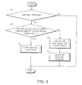
- Fig. 3 and Fig. 4 shows a main control routine executed by the controller 1 at an interval of 10 milliseconds.
- the timing charts shown in Fig. 5 and Fig. 6 show the state of various components over time during startup control.
- step S1 in Fig. 3 the elapsed time TMFPON after the ignition signal ING is placed in the ON position is counted up and compared with a reference value FPONTM.
- the controller 1 immediately terminates the routine without proceeding to subsequent steps until the elapsed time TMFPON reaches the reference value FPONTM.
- the set reference value FPONTM corresponds to the drive time of the fuel pump required to increase the fuel pressure in the fuel pipe to a steady-state pressure. This set time prevents a shortfall in the fuel injection amount during initial fuel injection after cranking startup.
- the routine proceeds to a step S2 and the routine shifts to fuel/ignition control during cranking.
- step S2 when the first cylinder-stroke identification signal or the first REF signal is input after the time elapse for fuel pressure increase, the routine proceeds to a step S3.
- step S3 control is performed so that the fuel injection pattern is determined to be simultaneous injection to all cylinders or sequential injection through the stroke sequence to each cylinder or each cylinder group.
- step S2 when the first REF signal or the cylinder-stroke identification signal has not been input, the routine proceeds to a step S4 and the calculation of the fuel injection pulse width is performed at a control cycle of 10 milliseconds for example.
- step S5 ignition control is performed as described hereafter.
- Fig. 4 shows a main control routine for the fuel injection pattern after the time elapse for the fuel pressure increase when starting cranking as executed in the step S3.
- a step S6 when the input frequency of the REF signal is compared with a predetermined value (for a four-cylinder engine, this is set to a value of four and is a value which depends on the number of cylinders). This is in order to determine whether or not an initial startup period has elapsed. If the input frequency of the REF signal is greater than or equal to the predetermined value, it means that the initial startup period is finished and control has entered the normal injection period. In this case, the routine proceeds to a step S10 and fuel injection control is executed using the fuel injection completion timing as a reference.
- a predetermined value for a four-cylinder engine
- the routine proceeds to a step S7.
- the water temperature TWINT detected by the cooling water temperature sensor 15 at cranking startup is compared with a reference value corresponding to a predetermined water temperature of - 15 degrees C.
- the routine proceeds to a step S9 and fuel injection control is executed based on the reference value for the fuel injection startup timing during extremely low temperatures.
- the routine proceeds to a step S8 and a control routine is performed using the reference value for the fuel injection startup timing reference for normal water temperatures.
- Fig. 5 shows the fuel injection control when the water temperature at cranking startup is normal.
- Fig. 5E when the first REF signal is input, a predetermined fuel amount is injected simultaneously into all cylinders in synchrony with the REF signal input timing as shown in Fig. 5 I, J, K and L.
- Fig. 5F when the first cylinder identification signal is input after the time elapse for fuel pressure increase, an injection operation is performed on the group of cylinders undergoing an intake stroke or an exhaust stroke in synchrony with the input timing of the cylinder identification signal.
- Fig. 6 shows the fuel injection control routine during extremely low temperatures when the water temperature at cranking startup is less than TWINT.
- Fuel injection to all cylinders as shown in Fig. 5 and Fig. 6 comprises supply of an amount of fuel which can not injected during a first injection operation immediately after cylinder identification due to the above characteristics of the fuel injector 8. Thus it is sometimes the case that an injection operation is not required as a result of temperature conditions or the current state of the fuel injector 8. Furthermore irrespective of the water temperature at cranking startup, after the input frequency of the REF signal reaches a predetermined value, the routine shifts to injection completion timing reference control. Consequently sequential fuel injection is performed in synchrony with the stroke position of each cylinder so that injection is completed at a predetermined timing during the exhaust stroke of the cylinder.
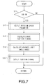
- Fig. 7 shows a main control routine for ignition control executed at a fixed repetition period by the controller 1. This control is executed at a period of 10 milliseconds.
- step S11 the state of the ignition switch is determined and when the ignition signal ING is in the ON position, the calculation of the ignition timing is performed in the step S12 and subsequent steps.
- the routine is immediately terminated.
- a rotation speed expressed by the POS signal which has a rapid updating period or the rotation speed expressed by the REF signal which has a slow updating period is selected as the rotation speed parameter used in the calculation of the ignition timing.
- the selection of the rotation speed parameter will be described in detail below.
- the basic ignition timing is calculated using a rotation speed selected in the step S12.
- the calculation of the basic ignition timing is performed by referring to a table defining a basic ignition timing with respect to load and rotation speed of the engine for example.
- a set value for the advance limit and the dwell angle are determined in order to restrict the maximum advance for a single control cycle during a transient condition (including startup state) or by a steady-state operating condition.
- an ignition signal is output based on the dwell angle and the advance limit, and the basic ignition timing set in the above manner.
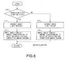
- Fig. 8 is a subroutine for setting the current-carrying angle and the advance limit in the step S14 performed by the controller 1.
- Fig. 9 is a timing chart representing the operation based on this control.
- a step S16 it is determined whether or not the vehicle is in a startup state. This determination is performed based on whether the ignition signal ING and the start signal STSG are in the ON position.
- the routine proceeds to a step S17 and ADVLMTS is selected as the advance limit between each REF signal.
- ADVLMTS is selected as the advance limit between each REF signal.
- ADVLMT normally corresponds to the general advance limit.
- the values ADVLMTS and ADVLMT display a relationship such that ADVLMTS is greater than ADVLMT.
- the limits are pre-stored in the memory of the controller 1.
- the routine proceeds to a step S18 and the dwell angle TDWLLB is calculated.
- This calculation process comprises multiplying the voltage correction by the rotation speed equivalence value set by looking up a table in response to the engine rotation speed and then adding the advance limit ADVLMTS selected in a step S17 to the resulting value.
- the voltage correction is a value which increases as the battery voltage decreases.
- the dwell angle TDWLLB is calculated which corresponds to the current-carrying period for the ignition current in a step S20.
- This value TDWLLB is calculated by multiplying the voltage correction with the rotation speed equivalence value and then adding the advance limit ADVLMT selected in the step S19.
- the dwell angle takes a larger value during startup conditions.
- Fig. 9 shows ignition timing characteristics in engine startup conditions when performing the above process.
- ADVLMTS is selected as the advance limit. Since this value is larger than ADVLMT which is the normal advance limit as shown by the broken line, a large advance is possible since the ignition timing set based on the rotation speed is not restricted by the limit.
- the value for the dwell angle is also set to a large dwell angle. In this manner, it is possible to ensure ignition of the air-fuel mixture during engine startup conditions and generate a sufficiently large torque. Thus it is possible to improve startability and to prevent flameout or incomplete combustion as well as preventing adverse effects on exhaust emission control resulting from these factors.
- Fig. 10 is a subroutine for another embodiment performed by the controller 1 related to setting the dwell angle and the advance limit.
- Fig. 11 is a timing chart expressing an operation based on that control.
- step S23 that is to say, the process for calculating the dwell angle TDWLLB after setting the transient advance limit ADVLMTS is different from the step S18 in Fig. 8.
- a correction coefficient DWLHOS (where DWLHOS is greater than one) is set and this value is multiplied by the voltage correction and the rotation speed equivalence value set in response to the engine rotation speed.
- the advance limit ADVLMTS set in a step S22 is then added to these values.
- the dwell angle takes a sufficiently large value with the result that the dwell angle is set to a value which contains a margin which also take into account conditions under which the rotation speed increases rapidly such as during engine startup. Consequently ignition operations are ensured.
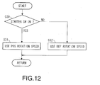
- Fig. 12 shows a subroutine for embodiment of ignition control executed by the controller.
- Fig. 13 is a timing chart showing an operation based on the above control.
- step S30 it is determined whether or not the starter signal STSG from the ignition switch 13 is in the ON position.
- the routine proceeds to a step S31 and the rotation speed (hereafter referred to as the "POS rotation speed") calculated based on the output period of the POS signal from the crank angle sensor 9 is used as the rotation speed parameter from setting the ignition timing.
- the rotation speed hereafter referred to as the "POS rotation speed”
- the POS rotation speed is used as a rotation speed parameter for setting the ignition timing in the process performed in the step S13 and subsequent steps as shown in Fig. 7.
- the routine proceeds to a step S32 and the rotation speed (hereafter referred to as the "REF rotation speed") calculated based on the output period of the REF signal from the crank angle sensor 9 is used as the rotation speed parameter from setting the ignition timing.
- the rotation speed hereafter referred to as the "REF rotation speed”
- the POS signal is output per unit rotational angle of the crankshaft 10, for example at a period of 1 deg.
- the REF signal is outputted at a pre-set reference position of the crankshaft 10. Consequently under operating conditions such as during startup when the rotation speed increases rapidly, the POS rotation speed which is updated at a more rapid cycle expresses a rotation speed which is closer to the real rotation speed than the REF rotation speed which is updated at a slower cycle.
- the POS rotation speed is used during startup conditions as the rotation speed parameter for setting the ignition timing, it is possible to perform a setting to an ignition timing which is closer to an optimal ignition timing for the engine rotation speed.
- Fig. 13F shows an ignition timing calculated based on the POS rotation speed and the REF rotation speed. A larger advance can be applied to an ignition timing calculated based on the POS rotation speed. Thus it is possible for the ignition timing as well as the dwell angle to approach the required value.
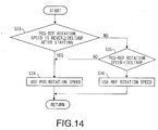
- Fig. 14 shows a subroutine for another embodiment of a process for selecting the rotation speed parameter performed by the controller 1.
- Fig. 15 is a timing chart describing an operation based on this control.
- a step S33 it is determined whether or not the differential of the POS rotation speed and the REF rotation speed has taken a larger value than the predetermined value on any occasion after the engine was started. That is to say, it is determined whether the POS rotation speed - REF rotation speed is greater than or equal to DELTARP.
- D, E the period in which the differential is small, corresponds to a region after engine startup until the rotation speed starts to increase.
- the predetermined value DELTARP is a value which corresponds to a value at which the variation in the engine rotation speed is not very high.
- the routine proceeds to a step S34 and the POS rotation speed is selected as the rotation speed parameter.
- a step S33 when it is determined that relationship POS rotation speed -REF rotation speed is greater than or equal to DELTARP has been satisfied even on a single occasion, the routine proceeds to a step S35.
- step S35 it is determined whether or not POS rotation speed - REF rotation speed is smaller than DELTARP.
- step S35 when the POS rotation speed - the REF rotation speed is smaller then DELTARP, the routine proceeds to a step S36 and the REF rotation speed is selected as a rotation speed parameter.
- This state corresponds to a region in Fig. 15 in which the increase in the rotation speed has stopped and the differential of the REF rotation speed and the POS rotation speed has decreased.
- Fig. 15E while the engine rotation speed is increasing, the differential between the two rotation speeds is large.
- the REF rotation speed is larger than the POS rotation speed and the rotation speed differential takes a negative value.
- Fig. 16 shows a subroutine for another embodiment of a process of selecting a rotation speed parameter performed by the controller 1.
- Fig. 17 is a timing chart describing an operation based on the above control routine.
- a differential between the POS rotation speed and the REF rotation speed is mainly generated during startup conditions.
- the degree of variation in the rotation speed that is to say, the differential of the rotation speed is used to determine a initial combustion being startup of combustion operations.
- Selection of the rotation speed parameter is performed by determining whether or not initial combustion has occurred.
- the amount of variation in the rotation speed as represented by the differential of the rotation speed in the step S37 is compared with the predetermined set value.
- the set value corresponds to a rotational acceleration at which the engine rotational acceleration undergoes independent motion due to initial combustion.
- the routine proceeds to a step S40 and the POS rotation speed is selected as the rotation speed parameter.
- the routine proceeds to a step S38 and the rotation speed of the crankshaft after the amount of variation in the rotation speed becomes greater than or equal to a set value is measured.
- the measured rotation speed is compared with a predetermined value. This predetermined value is set to a value which corresponds to the period after initial combustion until the engine rotation speed reaches an idle rotation speed.
- the routine proceeds to a step S40 and the POS rotation speed is maintained as the parameter for rotation speed.
- the routine proceeds to a step S39 and the REF rotation speed is selected a the rotation speed parameter.
- Fig. 18 is a flowchart for another embodiment of selecting a rotation speed parameter executed by the controller 1 during transient operating conditions other than during startup.
- a value obtained by subtracting the REF rotation speed from the POS rotation speed is compared with the pre-set reference value DELTARP.
- the reference value DELTARP is the same as that shown in Fig. 14 and is a value at which there is not a large variation in the engine speed.
- the routine proceeds to a step S43, and the REF rotation speed is used as the rotation speed parameter used in order to set the ignition timing (step S43).
- the POS rotation speed is used as the rotation speed parameter for setting the ignition timing.
Abstract
Description
- This invention relates to ignition timing control for an internal combustion engine.
- JP-A 2001-82302 published by the Japanese Patent Office in 2001 discloses a control device which uses rotation speed as a parameter in order to calculate an ignition timing.
- The ignition timing is calculated and set on the basis of successive REF signals defining a reference position of the crankshaft. The REF signals comprise a detection signal from a crank angle sensor. As a result, particularly when starting the engine, during transient operating states in which the engine rotation speed increases rapidly from a low rotation speed in a short period, the fluctuation in the rotation speed between the interval of the input of REF signals increases, consequently the problem arises that a required ignition advance can not be obtained.
- The dimension of the advance per ignition signal control cycle is restricted by an advance limit. If the engine rotation speed reaches a certain speed and the advance per control cycle is increased, there is the possibility that misfiring will occur due to an insufficient current-carrying angle (dwell angle) in the primary current. This result may be prevented by restricting the advance by providing an advance limit. However during large fluctuations in the rotation speed, it is not possible to perform an advancing operation up to an optimal ignition timing (for example, an MBT minimum advance for best torque) due to the limit on the advance. As a result, optimal combustion conditions can not be realized.
- Furthermore if the engine rotation speed is represented as a REF signal, and in particular, when the REF signal comprises a long time interval such as that during startup, the deviation of the actual rotation speed from the rotation speed calculated using the REF signal increases and generally the rotation speed appears to decrease. Consequently the generated torque may be reduced due to the fact that the calculated ignition timing tends to act as a retard on the optimal ignition timing. Alternatively, the generated torque may be reduced as a result of the calculated current-carrying time shortening relative to an optimal current-carrying time and thus resulting in a reduction in the ignition energy.
- Decreases in torque during transient operating states result in adverse effects on performance and in particular, constitute a cause of adverse effects on exhaust emission control and startability during startup conditions.
- It is therefore an object of this invention to enable rapid advancing operations up to a suitable ignition timing during transient operating states including engine startup.
- In order to achieve the above object the invention provides an ignition control device for an internal combustion engine, the internal combustion engine comprises a spark plug provided in a combustion chamber and an ignition coil supplying an ignition current to the spark plug, the ignition coil controlling an ignition current supplied to the spark plug based on a supplied primary current. The ignition control device comprises a first sensor detecting a rotation speed of the engine crankshaft, a second sensor detecting a transient operating state of the engine; and a controller. The controller functions to determine a transient engine operating state based on the output of the second sensor ; calculate the basic ignition timing based on the rotation speed; set an advance limit which is the maximum value of the advance on the ignition timing to a different value during a transient operating state and during a steady-state operating state, the value during a transient operating state being the larger value; set the ignition timing by using the limit to restrict the advance on the basic ignition timing, the basic ignition timing being calculated based on the rotation speed; calculate a dwell angle comprising the period of application of an ignition current in response to the rotation speed; and control the primary current supplied to the ignition coil based on the ignition timing and the dwell angle.
- The details as well as other features and advantages of the invention are set forth in the remainder of the specification and are shown in the accompanying drawings.
- Fig. 1 is a schematic figure of an internal combustion engine adapting this invention.
Fig. 2 is a block diagram describing the functions of a controller according to this invention.
Fig. 3 is a flowchart of a main control routine for startup fuel injection control performed by the controller. - Fig. 4 is a flowchart of a main control routine for fuel injection control performed by the controller.
- Fig. 5 is a timing chart describing a fuel injection pattern in a normal temperature region performed by the controller.
- Fig. 6 is a timing chart describing a fuel injection pattern in a low temperature region performed by the controller.
- Fig. 7 is a flowchart describing a main routine for ignition control performed by the controller.
- Fig. 8 is a flowchart describing a subroutine for ignition control performed by the controller.
- Fig. 9 is a timing chart describing an ignition pattern during the ignition control shown in Fig. 8 which is performed by the controller.
- Fig. 10 is a flowchart describing the subroutine for another embodiment of ignition control performed by the controller.
- Fig. 11 is a timing chart describing an ignition pattern during the ignition control shown in Fig. 10 performed by the controller.
- Fig. 12 is a flowchart describing a subroutine for yet another embodiment of ignition control performed by the controller.
- Fig. 13 is a timing chart describing an ignition pattern during the ignition control shown in Fig. 12 performed by the controller.
- Fig. 14 is a flowchart describing a subroutine for yet another embodiment of ignition control performed by the controller.
- Fig. 15 is a timing chart describing an ignition pattern during the ignition control shown in Fig. 14 performed by the controller.
- Fig. 16 is a flowchart describing yet another embodiment of ignition control performed by the controller.
- Fig. 17 is a timing chart describing an ignition pattern during the ignition control shown in Fig. 16 performed by the controller.
- Fig. 18 is a flowchart describing yet another embodiment of ignition control performed by the controller.
- Referring to Fig. 1, a four-
cylinder gasoline engine 2 for a vehicle is provided with anexhaust pipe 17 and anair intake pipe 3. Theair intake pipe 3 is connected to theair intake ports 7 for the respective cylinders. Afuel injector 8 for injecting fuel into each cylinder is provided in theair intake port 7. Theair intake port 7 is connected to the combustion chamber 6 and is opened and closed by anair intake valve 18. - A
spark plug 14 is provided in the combustion chamber 6 and ignites and combusts a gaseous mixture of air and fuel injected by thefuel injector 8. An ignition current from anignition coil 21 is supplied to thespark plug 14. - The combustion chamber 6 is connected to an
exhaust port 20. Anexhaust valve 19 is provided to open and close theexhaust port 20. Combustion gas combusted in the combustion chamber 6 is discharged from theexhaust port 20 and flows into theexhaust pipe 17. - A
controller 1 is provided in order to control the ignition timing of thespark plug 14 and the injection amount of fuel from thefuel injector 8. Thecontroller 1 comprises a microcomputer provided with a central processing unit (CPU), a read only memory (ROM), a random access memory (RAM) and an input/output interface (I/O interface). Thecontroller 1 controls the ignition of thespark plug 14 and the fuel injection of thefuel injector 8 based on various types of signals representing the operating state of the engine. - For this purpose, signals are inputted to the
controller 1 from anair flow meter 4 which detects an intake air amount Qc from theair intake pipe 3, awater temperature sensor 15 which detects a cooling water temperature Tw of theengine 2, an air-fuel ratio sensor 15 which detects an air-fuel ratio A/F of the gaseous mixture based on the oxygen concentration in the exhaust gas, acrank angle sensor 9 which detects the rotation position of thecrankshaft 10 of theengine 2 and acam position sensor 11 which detects a specific rotation position of acam 12 driving theexhaust valve 19 in each cylinder. Respective detection signals from theignition switch 13 are also inputted into thecontroller 1. - The
crank angle sensor 9 is a crank angle sensor for detecting an engine rotation speed and a rotational angle of thecrankshaft 10 and outputs POS signal and REF signals in the form of a pulse. The POS signal is outputted per unit rotational angle of thecrankshaft 10, for example at a period of 1 deg. The REF signal is outputted at a pre-set reference position of thecrankshaft 10. - The
ignition switch 13 outputs different signals depending on an operating position and outputs an ignition signal IGN to thecontroller 1 and a starter signal STSG which activates a starter motor. - The
cam position sensor 11 is a cam position sensor for detecting a rotation position of acam shaft 12 and outputs a pulse PHASE signal in the form of a pulse when thecam shaft 12 reaches a pre-set rotation position. - Fig. 2 shows the functions of the
controller 11 related to fuel injection control and ignition control. - The
controller 1 is provided with acranking determination unit 101, a cylinder-stroke identification unit 102, a rotationspeed calculation unit 103, an injection pulsewidth calculation unit 104, a drivesignal output unit 105, an injection starttiming calculation unit 106, an ignitionsignal output unit 107 and an ignitionsignal calculation unit 108. - The
cranking determination unit 101 determines cranking startup based on the starter signal STSG and the ignition signal ING from theignition switch 13. The cylinder-stroke identification unit 102 determines the position and stroke of each cylinder of theengine 2 based on the PHASE signal from thecam position sensor 11 and the POS signal from thecrank angle sensor 9. The rotationspeed calculation unit 103 calculates the rotation speed Ne of the engine based on the generation period of the POS signal and the REF signal. The injection pulsewidth calculation unit 104 calculates the basic fuel injection pulse width by looking up a table based on the intake air amount Qc detected by theair flow meter 4 and the calculated engine rotation speed Ne. Various types of corrections are added to the basic fuel injection amount based on the air-fuel ratio A/F of the exhaust gas detected by the air-fuel ratio sensor 16 or the water temperature signal Tw detected by thewater temperature sensor 15. In this manner, an injection amount command value is determined in order to drive theengine 2 at a target air-fuel ratio. The injection start timingcalculation unit 106 determines the start timing for fuel injection in response to fuel injection conditions. - The drive
signal output unit 105 outputs a drive signal to thefuel injector 8 based on the injection amount command value and the injection start timing. - The ignition
signal calculation unit 108 calculates the ignition timing and the dwell angle using the rotation speed calculated from the POS signal and the REF signal. The ignitionsignal output unit 107 outputs a primary current to theignition coil 21 according to the dwell angle and the ignition timing calculated by the ignitionsignal calculation unit 108 by referring to the REF signal and the POS signal. Theignition coil 21 supplies thespark plug 14 with an ignition current by producing a high-voltage secondary current based on the primary current. Thespark plug 14 performs an ignition operation when supplied with the ignition current and ignites and combusts the air-fuel mixture in the combustion chamber 6. - Next fuel injection control during engine startup will be described referring to the flowchart in Fig. 3 and Fig. 4. Fig. 3 and Fig. 4 shows a main control routine executed by the
controller 1 at an interval of 10 milliseconds. The timing charts shown in Fig. 5 and Fig. 6 show the state of various components over time during startup control. - In a step S1 in Fig. 3, the elapsed time TMFPON after the ignition signal ING is placed in the ON position is counted up and compared with a reference value FPONTM. The
controller 1 immediately terminates the routine without proceeding to subsequent steps until the elapsed time TMFPON reaches the reference value FPONTM. - The set reference value FPONTM corresponds to the drive time of the fuel pump required to increase the fuel pressure in the fuel pipe to a steady-state pressure. This set time prevents a shortfall in the fuel injection amount during initial fuel injection after cranking startup.
- Once the elapsed time TMFPON reaches the reference value FPONTM, the routine proceeds to a step S2 and the routine shifts to fuel/ignition control during cranking.
- In a step S2, when the first cylinder-stroke identification signal or the first REF signal is input after the time elapse for fuel pressure increase, the routine proceeds to a step S3. In the step S3, control is performed so that the fuel injection pattern is determined to be simultaneous injection to all cylinders or sequential injection through the stroke sequence to each cylinder or each cylinder group.
- In the step S2, when the first REF signal or the cylinder-stroke identification signal has not been input, the routine proceeds to a step S4 and the calculation of the fuel injection pulse width is performed at a control cycle of 10 milliseconds for example. In a step S5, ignition control is performed as described hereafter.
- Fig. 4 shows a main control routine for the fuel injection pattern after the time elapse for the fuel pressure increase when starting cranking as executed in the step S3.
- In a step S6, when the input frequency of the REF signal is compared with a predetermined value (for a four-cylinder engine, this is set to a value of four and is a value which depends on the number of cylinders). This is in order to determine whether or not an initial startup period has elapsed. If the input frequency of the REF signal is greater than or equal to the predetermined value, it means that the initial startup period is finished and control has entered the normal injection period. In this case, the routine proceeds to a step S10 and fuel injection control is executed using the fuel injection completion timing as a reference.
- When the input frequency of the REF signal is determined to be less than a predetermined value, the routine proceeds to a step S7. In the step S7, the water temperature TWINT detected by the cooling
water temperature sensor 15 at cranking startup is compared with a reference value corresponding to a predetermined water temperature of - 15 degrees C. - When the water temperature TWINT is lower than the reference value, the routine proceeds to a step S9 and fuel injection control is executed based on the reference value for the fuel injection startup timing during extremely low temperatures.
- In contrast, when the water temperature TWINT is greater than or equal to the predetermined reference value, the routine proceeds to a step S8 and a control routine is performed using the reference value for the fuel injection startup timing reference for normal water temperatures.
- Fig. 5 shows the fuel injection control when the water temperature at cranking startup is normal. After the time elapse for fuel pressure increase, as shown in Fig. 5E, when the first REF signal is input, a predetermined fuel amount is injected simultaneously into all cylinders in synchrony with the REF signal input timing as shown in Fig. 5 I, J, K and L. In Fig. 5F, when the first cylinder identification signal is input after the time elapse for fuel pressure increase, an injection operation is performed on the group of cylinders undergoing an intake stroke or an exhaust stroke in synchrony with the input timing of the cylinder identification signal.
- When the inputted signal after the time elapse for the fuel pressure increase is neither the first REF signal or a cylinder identification signal, that is to say, when the first fuel injection has already been performed, as shown in Fig. 5 I, J, K, and L, fuel injection is performed on the next cylinder in order after passing through a crank angle set by the command value VDINJ1 on the basis of the input timing of the REF signal. However fuel injection is not performed with respect to cylinders which have already undergone group injection. The command value VDINJ1 is set so that the fuel injection operation performed at this time is performed during the exhaust stroke.
- Fig. 6 shows the fuel injection control routine during extremely low temperatures when the water temperature at cranking startup is less than TWINT.
- After fuel pressure increase time has elapsed, as shown in Fig. 6E, when the first REF signal is inputted, as shown in Fig. 6 I, J, K and L, simultaneous injection is performed on all cylinders in synchrony with the input timing of the REF signal. Furthermore when the first cylinder identification signal after the fuel pressure increase time has elapsed is input as shown in Fig. 6F, a fuel injection operation is performed on cylinders undergoing an intake stroke in synchrony with the input timing of the cylinder identification signal.
- When the inputted signal is neither the first REF signal after the time elapse for fuel pressure increase or the first cylinder identification signal, as shown in Fig. 6 I, J, K, and L, fuel injection is performed on the next cylinder in order after elapse of the crank angle set by the command value VDINJ2 on the basis of the input timing of the REF signal. The command value VDINJ2 is set so that the fuel injection operation performed at this time is performed during the intake stroke.
- Fuel injection to all cylinders as shown in Fig. 5 and Fig. 6 comprises supply of an amount of fuel which can not injected during a first injection operation immediately after cylinder identification due to the above characteristics of the
fuel injector 8. Thus it is sometimes the case that an injection operation is not required as a result of temperature conditions or the current state of thefuel injector 8. Furthermore irrespective of the water temperature at cranking startup, after the input frequency of the REF signal reaches a predetermined value, the routine shifts to injection completion timing reference control. Consequently sequential fuel injection is performed in synchrony with the stroke position of each cylinder so that injection is completed at a predetermined timing during the exhaust stroke of the cylinder. - In this manner, when fuel injection is performed in synchrony with the cylinder identification timing for each cylinder, preferred exhaust emission control and startability are obtained by optimizing the air-fuel ratio of each cylinder. However as described above, it is preferred that the ignition timing is more accurately controlled in order to ensure the above result. Next ignition timing control for that purpose will be described.
- Fig. 7 shows a main control routine for ignition control executed at a fixed repetition period by the
controller 1. This control is executed at a period of 10 milliseconds. - In a step S11, the state of the ignition switch is determined and when the ignition signal ING is in the ON position, the calculation of the ignition timing is performed in the step S12 and subsequent steps. When the ING signal is not in the ON position, the routine is immediately terminated.
- In a step S12, either a rotation speed expressed by the POS signal which has a rapid updating period or the rotation speed expressed by the REF signal which has a slow updating period is selected as the rotation speed parameter used in the calculation of the ignition timing. The selection of the rotation speed parameter will be described in detail below.
- When the routine proceeds to a step S13, the basic ignition timing is calculated using a rotation speed selected in the step S12.
- The calculation of the basic ignition timing is performed by referring to a table defining a basic ignition timing with respect to load and rotation speed of the engine for example.
- In a step S14, a set value for the advance limit and the dwell angle are determined in order to restrict the maximum advance for a single control cycle during a transient condition (including startup state) or by a steady-state operating condition.
- Then in a step S15, an ignition signal is output based on the dwell angle and the advance limit, and the basic ignition timing set in the above manner.
- Fig. 8 is a subroutine for setting the current-carrying angle and the advance limit in the step S14 performed by the
controller 1. Fig. 9 is a timing chart representing the operation based on this control. - In Fig. 8, in a step S16, it is determined whether or not the vehicle is in a startup state. This determination is performed based on whether the ignition signal ING and the start signal STSG are in the ON position.
- When it is determined that the vehicle is in a startup state, the routine proceeds to a step S17 and ADVLMTS is selected as the advance limit between each REF signal. In states other than a startup state, that is to say, when it is determined that the vehicle is operating in a steady-state condition, ADVLMT is selected as the advance limit between each REF signal.
- ADVLMT normally corresponds to the general advance limit. The values ADVLMTS and ADVLMT display a relationship such that ADVLMTS is greater than ADVLMT. The limits are pre-stored in the memory of the
controller 1. - When ADVLMTS is selected, the routine proceeds to a step S18 and the dwell angle TDWLLB is calculated. This calculation process comprises multiplying the voltage correction by the rotation speed equivalence value set by looking up a table in response to the engine rotation speed and then adding the advance limit ADVLMTS selected in a step S17 to the resulting value. However the voltage correction is a value which increases as the battery voltage decreases.
- Furthermore when it is determined that the vehicle is operating in conditions other than startup in a step S16 and when ADVLMT is selected in a step S19, the dwell angle TDWLLB is calculated which corresponds to the current-carrying period for the ignition current in a step S20. This value TDWLLB is calculated by multiplying the voltage correction with the rotation speed equivalence value and then adding the advance limit ADVLMT selected in the step S19.
- Since ADVLMTS which is larger than ADVLMT is selected as the advance limit during startup conditions, the dwell angle takes a larger value during startup conditions.
- Fig. 9 shows ignition timing characteristics in engine startup conditions when performing the above process.
- As shown in Fig. 9 C, D, when the rotation speed increases during startup, ADVLMTS is selected as the advance limit. Since this value is larger than ADVLMT which is the normal advance limit as shown by the broken line, a large advance is possible since the ignition timing set based on the rotation speed is not restricted by the limit.
- Consequently it is possible to perform an advancing operation towards an optimal ignition timing in response to the increase in the rotation speed during startup more rapidly than the conventional example shown by the broken line.
- As shown in Fig. 9 F, G, the value for the dwell angle is also set to a large dwell angle. In this manner, it is possible to ensure ignition of the air-fuel mixture during engine startup conditions and generate a sufficiently large torque. Thus it is possible to improve startability and to prevent flameout or incomplete combustion as well as preventing adverse effects on exhaust emission control resulting from these factors.
- Fig. 10 is a subroutine for another embodiment performed by the
controller 1 related to setting the dwell angle and the advance limit. Fig. 11 is a timing chart expressing an operation based on that control. - In Fig. 10, the steps S21, S22, S24, S25 are the same as the steps S16, S17, S19, S20 in Fig. 8.
- The process in the step S23, that is to say, the process for calculating the dwell angle TDWLLB after setting the transient advance limit ADVLMTS is different from the step S18 in Fig. 8.
- That is to say, in a step S23, a correction coefficient DWLHOS (where DWLHOS is greater than one) is set and this value is multiplied by the voltage correction and the rotation speed equivalence value set in response to the engine rotation speed. The advance limit ADVLMTS set in a step S22 is then added to these values.
- Consequently it is possible for the dwell angle TDWLLB to take even larger values as a result of applying the correction coefficient DWLHOS.
- Referring to Fig. 11, as shown in Fig. 11 D, E, the dwell angle takes a sufficiently large value with the result that the dwell angle is set to a value which contains a margin which also take into account conditions under which the rotation speed increases rapidly such as during engine startup. Consequently ignition operations are ensured.
- The process of selecting the rotation speed parameter in the
step 12 shown in Fig. 7 as executed by thecontroller 1 will be described in detail below. - Fig. 12 shows a subroutine for embodiment of ignition control executed by the controller. Fig. 13 is a timing chart showing an operation based on the above control.
- In Fig. 12, firstly in a step S30, it is determined whether or not the starter signal STSG from the
ignition switch 13 is in the ON position. - When the starter signal STSG is in the ON position, the routine proceeds to a step S31 and the rotation speed (hereafter referred to as the "POS rotation speed") calculated based on the output period of the POS signal from the
crank angle sensor 9 is used as the rotation speed parameter from setting the ignition timing. - That is to say, the POS rotation speed is used as a rotation speed parameter for setting the ignition timing in the process performed in the step S13 and subsequent steps as shown in Fig. 7.
- In contrast, when the starter signal STSG is in the OFF position, the routine proceeds to a step S32 and the rotation speed (hereafter referred to as the "REF rotation speed") calculated based on the output period of the REF signal from the
crank angle sensor 9 is used as the rotation speed parameter from setting the ignition timing. - The POS signal is output per unit rotational angle of the
crankshaft 10, for example at a period of 1 deg. The REF signal is outputted at a pre-set reference position of thecrankshaft 10. Consequently under operating conditions such as during startup when the rotation speed increases rapidly, the POS rotation speed which is updated at a more rapid cycle expresses a rotation speed which is closer to the real rotation speed than the REF rotation speed which is updated at a slower cycle. - Thus when the POS rotation speed is used during startup conditions as the rotation speed parameter for setting the ignition timing, it is possible to perform a setting to an ignition timing which is closer to an optimal ignition timing for the engine rotation speed.
- Fig. 13F shows an ignition timing calculated based on the POS rotation speed and the REF rotation speed. A larger advance can be applied to an ignition timing calculated based on the POS rotation speed. Thus it is possible for the ignition timing as well as the dwell angle to approach the required value.
- Fig. 14 shows a subroutine for another embodiment of a process for selecting the rotation speed parameter performed by the
controller 1. Fig. 15 is a timing chart describing an operation based on this control. - In Fig. 14, in a step S33, it is determined whether or not the differential of the POS rotation speed and the REF rotation speed has taken a larger value than the predetermined value on any occasion after the engine was started. That is to say, it is determined whether the POS rotation speed - REF rotation speed is greater than or equal to DELTARP.
- As shown in Fig. 15C, D, E, the period in which the differential is small, corresponds to a region after engine startup until the rotation speed starts to increase. Thus the predetermined value DELTARP is a value which corresponds to a value at which the variation in the engine rotation speed is not very high.
- When the differential between the POS rotation speed and the REF rotation speed is small, the routine proceeds to a step S34 and the POS rotation speed is selected as the rotation speed parameter.
- In a step S33, when it is determined that relationship POS rotation speed -REF rotation speed is greater than or equal to DELTARP has been satisfied even on a single occasion, the routine proceeds to a step S35. In the step S35, it is determined whether or not POS rotation speed - REF rotation speed is smaller than DELTARP.
- If the relationship POS rotation speed - REF rotation speed is greater than or equal to DELTARP is satisfied, it shows that the rotation speed is increasing. Consequently the routine proceeds to a step S34, and the POS rotation speed is selected as a rotation speed parameter. As a result, even during an increase in the rotation speed, it is possible to improve the response characteristics with which the ignition timing is advanced by calculating the ignition timing based on the POS rotation speed.
- In the step S35, when the POS rotation speed - the REF rotation speed is smaller then DELTARP, the routine proceeds to a step S36 and the REF rotation speed is selected as a rotation speed parameter.
- This state corresponds to a region in Fig. 15 in which the increase in the rotation speed has stopped and the differential of the REF rotation speed and the POS rotation speed has decreased. As shown in Fig. 15E, while the engine rotation speed is increasing, the differential between the two rotation speeds is large. When the rotation speed decreases, the REF rotation speed is larger than the POS rotation speed and the rotation speed differential takes a negative value.
- In regions in which the rotation speed differential is small, even when the ignition timing is calculated based on the REF rotation speed, it is possible to approximate the required ignition timing.
- Fig. 16 shows a subroutine for another embodiment of a process of selecting a rotation speed parameter performed by the
controller 1. Fig. 17 is a timing chart describing an operation based on the above control routine. - In this process, a differential between the POS rotation speed and the REF rotation speed is mainly generated during startup conditions. Thus as shown in Fig. 17D, the degree of variation in the rotation speed, that is to say, the differential of the rotation speed is used to determine a initial combustion being startup of combustion operations. Selection of the rotation speed parameter is performed by determining whether or not initial combustion has occurred.
- In Fig. 16, the amount of variation in the rotation speed as represented by the differential of the rotation speed in the step S37 is compared with the predetermined set value. The set value corresponds to a rotational acceleration at which the engine rotational acceleration undergoes independent motion due to initial combustion.
- When the amount of variation in the rotation speed is not greater than or equal to a set value, the routine proceeds to a step S40 and the POS rotation speed is selected as the rotation speed parameter.
- When the amount of variation in the rotation speed is greater than or equal to a set value, the routine proceeds to a step S38 and the rotation speed of the crankshaft after the amount of variation in the rotation speed becomes greater than or equal to a set value is measured. The measured rotation speed is compared with a predetermined value. This predetermined value is set to a value which corresponds to the period after initial combustion until the engine rotation speed reaches an idle rotation speed.
- As long as this period has not elapsed, the routine proceeds to a step S40 and the POS rotation speed is maintained as the parameter for rotation speed.
- In contrast, when the above period has elapsed, the routine proceeds to a step S39 and the REF rotation speed is selected a the rotation speed parameter.
- In this manner, during startup conditions in which the rotation speed undergoes a large variation, when the POS rotation speed is used as the rotation speed parameter for setting the ignition timing, it is possible to obtain a value which more closely approximates an optimal ignition timing for the engine rotation speed.
- Fig. 18 is a flowchart for another embodiment of selecting a rotation speed parameter executed by the
controller 1 during transient operating conditions other than during startup. - In each embodiment above, a selection process is described for the rotation speed parameter in order to set the ignition timing under engine startup conditions. However during conditions other than startup, the rotation speed undergoes large variations during acceleration for example. During this type of transient operation, it is possible to realize suitable ignition timing control by selecting the rotation speed parameter in the above manner.
- In a step S41 shown Fig. 18, a value obtained by subtracting the REF rotation speed from the POS rotation speed is compared with the pre-set reference value DELTARP. The reference value DELTARP is the same as that shown in Fig. 14 and is a value at which there is not a large variation in the engine speed.
- When the rotation speed differential is less than the reference value, the routine proceeds to a step S43, and the REF rotation speed is used as the rotation speed parameter used in order to set the ignition timing (step S43).
- In contrast, when the rotation speed differential is larger than the reference value, that is to say, when fluctuation in the rotation speed is high, in a step S42, the POS rotation speed is used as the rotation speed parameter for setting the ignition timing.
- Thus under conditions other than engine startup conditions, in other words, during transient conditions such as engine acceleration when fluctuation in the rotation speed is high, it is possible to make further improvements to the ignition timing by setting the ignition timing based on the POS ignition timing.The entire contents of Japanese Patent Application P2001-246499(filed August 15, 2001) is incorporated herein by reference.
- This invention is not limited to the above embodiments and may be changed in various ways within the scope of the inventive concept.
Claims (10)
- An ignition control device for an internal combustion engine, the internal combustion engine (2) comprising a spark plug (14) provided in a combustion chamber and an ignition coil (21) supplying an ignition current to the spark plug (14), the ignition coil (21) controlling an ignition current supplied to the spark plug (14) based on a supplied primary current; the ignition control device comprising:a first sensor (9) detecting a rotation speed of the engine crankshaft;a second sensor (13) detecting a transient operating state of the engine; anda controller (1) which functions todetermine a transient engine operating state based on the output of the second sensor (13);calculate the basic ignition timing based on the rotation speed;set an advance limit which is the maximum value of the advance on the ignition timing to a different value during a transient operating state and during a steady-state operating state, the value during a transient operating state being the larger value;set the ignition timing by using the limit to restrict the advance on the basic ignition timing, the basic ignition timing being calculated based on the rotation speed;calculate a dwell angle comprising the period of application of an ignition current in response to the rotation speed; andcontrol the primary current supplied to the ignition coil (21) based on the ignition timing and the dwell angle.
- The ignition control device as defined by Claim 1, wherein the controller (1) functions to increase the dwell angle for a transient operating state to a value greater than the value for a steady-state operating state.
- The ignition control device as defined by Claim 2, wherein the controller (1) functions to increase the dwell angle for a transient operating state based on the limit for a transient operating state.
- The ignition control device as defined by Claim 1, wherein the first sensor (9) is a sensor which outputs a REF signal showing a reference rotation position of the crankshaft and a POS signal showing the rotation amount.
- The ignition control device as defined by Claim 4, wherein the controller (1) functions to calculate a basic ignition timing using a rotation speed represented by the POS signal instead of the rotational speed represented by the REF signal when detecting a transient operating state.
- The ignition control device as defined by Claim 5, wherein the controller (1) functions to calculate a basic ignition timing using a rotation speed represented by the POS signal instead of a rotation speed represented by the REF signal, after the differential between the rotation speed represented by the REF signal and the rotation speed represented by the POS signal is greater than or equal to a reference value.
- The ignition control device as defined by Claim 5, wherein the controller (1) functions to calculate an amount of variation in the rotation speed; compare the calculated amount with a value corresponding to the amount of variation in the rotation speed at initial engine combustion; and calculate the basic ignition timing based on a rotation speed represented by the REF signal when the rotation frequency of the crankshaft after the calculated value exceeds the initial combustion equivalence value is greater than or equal to a reference value.
- The ignition control device as defined by Claim 5, wherein the second sensor (13) is am ignition switch for detecting engine startup.
- The ignition control device as defined by Claim 8, wherein the controller (1) functions to calculate a basic ignition timing using a rotation speed represented by the POS signal instead of the rotational speed represented by the REF signal when detecting a startup condition.
- The ignition control device as defined by Claim 9, wherein the controller (1) functions to calculate a basic ignition timing using a rotation speed represented by the POS signal instead of a rotation speed represented by the REF signal, after the differential between the rotation speed represented by the REF signal and the rotation speed represented by the POS signal is greater than or equal to a reference value.
Applications Claiming Priority (2)
| Application Number | Priority Date | Filing Date | Title |
|---|---|---|---|
| JP2001246499A JP3791364B2 (en) | 2001-08-15 | 2001-08-15 | Engine ignition timing control device |
| JP2001246499 | 2001-08-15 |
Publications (3)
| Publication Number | Publication Date |
|---|---|
| EP1284363A2 true EP1284363A2 (en) | 2003-02-19 |
| EP1284363A3 EP1284363A3 (en) | 2006-04-05 |
| EP1284363B1 EP1284363B1 (en) | 2008-10-08 |
Family
ID=19076032
Family Applications (1)
| Application Number | Title | Priority Date | Filing Date |
|---|---|---|---|
| EP02016929A Expired - Lifetime EP1284363B1 (en) | 2001-08-15 | 2002-07-31 | Ignition timing control device for internal combustion engine |
Country Status (4)
| Country | Link |
|---|---|
| US (1) | US6575150B2 (en) |
| EP (1) | EP1284363B1 (en) |
| JP (1) | JP3791364B2 (en) |
| DE (1) | DE60229189D1 (en) |
Cited By (3)
| Publication number | Priority date | Publication date | Assignee | Title |
|---|---|---|---|---|
| EP1464834A1 (en) * | 2003-04-03 | 2004-10-06 | Siemens Aktiengesellschaft | Method for optimizing the ignition of an air-fuel mixture for direct-start of combustion engine |
| EP2405122A4 (en) * | 2009-03-02 | 2018-03-07 | Hitachi Automotive Systems, Ltd. | Control device for internal combustion engine |
| CN110397514A (en) * | 2018-04-25 | 2019-11-01 | 丰田自动车株式会社 | Internal combustion engine and the hybrid vehicle for having the internal combustion engine |
Families Citing this family (10)
| Publication number | Priority date | Publication date | Assignee | Title |
|---|---|---|---|---|
| JP3997943B2 (en) * | 2003-04-21 | 2007-10-24 | 三菱電機株式会社 | Ignition control device for internal combustion engine |
| US8108120B2 (en) * | 2004-10-25 | 2012-01-31 | Frederico Griese | Bi-fuel conversion device for an internal combustion engine |
| JP4725555B2 (en) * | 2007-06-11 | 2011-07-13 | トヨタ自動車株式会社 | Control device for internal combustion engine |
| US8584650B2 (en) * | 2007-11-07 | 2013-11-19 | Ford Global Technologies, Llc | Ignition energy control for mixed fuel engine |
| KR101171905B1 (en) * | 2009-06-09 | 2012-08-07 | 기아자동차주식회사 | Ignition system of engine and control method thereof |
| EP2997251A4 (en) * | 2013-03-15 | 2018-01-31 | Combustion 8 Technologies LLC | Reducing fuel consumption of spark ignition engines |
| JP6609111B2 (en) | 2015-05-15 | 2019-11-20 | 株式会社Soken | Ignition device |
| JP6274188B2 (en) * | 2015-11-12 | 2018-02-07 | トヨタ自動車株式会社 | Ignition timing control device for internal combustion engine |
| JP6812065B2 (en) * | 2016-06-30 | 2021-01-13 | ダイハツ工業株式会社 | Internal combustion engine control device |
| JP7226205B2 (en) * | 2019-09-13 | 2023-02-21 | マツダ株式会社 | engine controller |
Citations (1)
| Publication number | Priority date | Publication date | Assignee | Title |
|---|---|---|---|---|
| JP2001246499A (en) | 2000-02-29 | 2001-09-11 | Daihen Corp | Assembly jig for butt welding member |
Family Cites Families (7)
| Publication number | Priority date | Publication date | Assignee | Title |
|---|---|---|---|---|
| JPS5948307B2 (en) * | 1979-02-23 | 1984-11-26 | 日産自動車株式会社 | Internal combustion engine ignition timing control device |
| JPS5820391B2 (en) * | 1979-09-27 | 1983-04-22 | 株式会社デンソー | Non-contact ignition device for internal combustion engines |
| US4380989A (en) * | 1979-11-27 | 1983-04-26 | Nippondenso Co., Ltd. | Ignition system for internal combustion engine |
| JP3393626B2 (en) * | 1994-09-19 | 2003-04-07 | 株式会社日立ユニシアオートモティブ | Ignition timing control device for internal combustion engine |
| EP1471240A2 (en) * | 1997-05-21 | 2004-10-27 | Nissan Motor Co., Ltd. | Transient control between two spark-ignited combustion states in engine |
| JP4320821B2 (en) | 1999-02-23 | 2009-08-26 | トヨタ自動車株式会社 | Fuel injection control device and fuel injection control method for internal combustion engine |
| JP2001082302A (en) * | 1999-09-10 | 2001-03-27 | Unisia Jecs Corp | Ignition timing control device of internal combustion engine |
-
2001
- 2001-08-15 JP JP2001246499A patent/JP3791364B2/en not_active Expired - Lifetime
-
2002
- 2002-07-31 EP EP02016929A patent/EP1284363B1/en not_active Expired - Lifetime
- 2002-07-31 DE DE60229189T patent/DE60229189D1/en not_active Expired - Lifetime
- 2002-08-12 US US10/216,173 patent/US6575150B2/en not_active Expired - Lifetime
Patent Citations (1)
| Publication number | Priority date | Publication date | Assignee | Title |
|---|---|---|---|---|
| JP2001246499A (en) | 2000-02-29 | 2001-09-11 | Daihen Corp | Assembly jig for butt welding member |
Cited By (4)
| Publication number | Priority date | Publication date | Assignee | Title |
|---|---|---|---|---|
| EP1464834A1 (en) * | 2003-04-03 | 2004-10-06 | Siemens Aktiengesellschaft | Method for optimizing the ignition of an air-fuel mixture for direct-start of combustion engine |
| EP2405122A4 (en) * | 2009-03-02 | 2018-03-07 | Hitachi Automotive Systems, Ltd. | Control device for internal combustion engine |
| CN110397514A (en) * | 2018-04-25 | 2019-11-01 | 丰田自动车株式会社 | Internal combustion engine and the hybrid vehicle for having the internal combustion engine |
| CN110397514B (en) * | 2018-04-25 | 2022-03-01 | 丰田自动车株式会社 | Internal combustion engine and hybrid vehicle provided with same |
Also Published As
| Publication number | Publication date |
|---|---|
| EP1284363A3 (en) | 2006-04-05 |
| JP3791364B2 (en) | 2006-06-28 |
| DE60229189D1 (en) | 2008-11-20 |
| US6575150B2 (en) | 2003-06-10 |
| EP1284363B1 (en) | 2008-10-08 |
| JP2003056439A (en) | 2003-02-26 |
| US20030034008A1 (en) | 2003-02-20 |
Similar Documents
| Publication | Publication Date | Title |
|---|---|---|
| EP1284363B1 (en) | Ignition timing control device for internal combustion engine | |
| KR19980070930A (en) | Inside injection engine control device | |
| US6904890B2 (en) | Start-up control of in-cylinder fuel injection spark ignition internal combustion engine | |
| EP1284349B1 (en) | Fuel injection control for start-up of internal combustion engine | |
| EP0924420B1 (en) | Torque controller for internal combustion engine | |
| KR19990013964A (en) | Apparatus and method for controlling ignition timing for internal combustion engines | |
| US7040296B2 (en) | Engine start control system and a method thereof | |
| EP1284350B1 (en) | Fuel injection control for internal combustion engine | |
| US6959242B2 (en) | Engine fuel injection control device | |
| US6568371B2 (en) | Fuel injection control for internal combustion engine | |
| EP1496229A2 (en) | Start-up control of direct injection engine | |
| JPH10339148A (en) | Engine intake controller | |
| EP1284353B1 (en) | Fuel injection control for start-up of internal combustion engine | |
| JPH0278746A (en) | Control device for air-fuel ratio of internal combustion engine | |
| JP2551378Y2 (en) | Electronically controlled fuel injection device for internal combustion engine | |
| JPH1136942A (en) | Fuel supply system of internal combustion engine | |
| JPH08218990A (en) | Device for judging start of internal combustion engine | |
| KR100264577B1 (en) | Idle speed control method at starting | |
| JPH1182079A (en) | Control system of direct-injection spark-ignition engine with variable valve system | |
| JPS63106340A (en) | Starting fuel injection quantity control method for internal combustion engine | |
| JP2008133794A (en) | Fuel injection control device | |
| JP2005016480A (en) | Control device for internal combustion engine | |
| JP2000073825A (en) | Fuel injection device for engine | |
| JPH09144591A (en) | Fuel property detecting device for internal combustion engine | |
| JPS6394041A (en) | Fuel injection amount control device for internal combustion engine |
Legal Events
| Date | Code | Title | Description |
|---|---|---|---|
| PUAI | Public reference made under article 153(3) epc to a published international application that has entered the european phase |
Free format text: ORIGINAL CODE: 0009012 |
|
| 17P | Request for examination filed |
Effective date: 20020731 |
|
| AK | Designated contracting states |
Designated state(s): AT BE BG CH CY CZ DE DK EE ES FI FR GB GR IE IT LI LU MC NL PT SE SK TR |
|
| AX | Request for extension of the european patent |
Extension state: AL LT LV MK RO SI |
|
| PUAL | Search report despatched |
Free format text: ORIGINAL CODE: 0009013 |
|
| AK | Designated contracting states |
Kind code of ref document: A3 Designated state(s): AT BE BG CH CY CZ DE DK EE ES FI FR GB GR IE IT LI LU MC NL PT SE SK TR |
|
| AX | Request for extension of the european patent |
Extension state: AL LT LV MK RO SI |
|
| 17Q | First examination report despatched |
Effective date: 20060919 |
|
| AKX | Designation fees paid |
Designated state(s): DE FR GB |
|
| 17Q | First examination report despatched |
Effective date: 20060919 |
|
| GRAP | Despatch of communication of intention to grant a patent |
Free format text: ORIGINAL CODE: EPIDOSNIGR1 |
|
| GRAS | Grant fee paid |
Free format text: ORIGINAL CODE: EPIDOSNIGR3 |
|
| GRAA | (expected) grant |
Free format text: ORIGINAL CODE: 0009210 |
|
| AK | Designated contracting states |
Kind code of ref document: B1 Designated state(s): DE FR GB |
|
| REG | Reference to a national code |
Ref country code: GB Ref legal event code: FG4D |
|
| REF | Corresponds to: |
Ref document number: 60229189 Country of ref document: DE Date of ref document: 20081120 Kind code of ref document: P |
|
| PLBE | No opposition filed within time limit |
Free format text: ORIGINAL CODE: 0009261 |
|
| STAA | Information on the status of an ep patent application or granted ep patent |
Free format text: STATUS: NO OPPOSITION FILED WITHIN TIME LIMIT |
|
| 26N | No opposition filed |
Effective date: 20090709 |
|
| REG | Reference to a national code |
Ref country code: FR Ref legal event code: PLFP Year of fee payment: 15 |
|
| REG | Reference to a national code |
Ref country code: FR Ref legal event code: PLFP Year of fee payment: 16 |
|
| REG | Reference to a national code |
Ref country code: FR Ref legal event code: PLFP Year of fee payment: 17 |
|
| PGFP | Annual fee paid to national office [announced via postgrant information from national office to epo] |
Ref country code: FR Payment date: 20210611 Year of fee payment: 20 |
|
| PGFP | Annual fee paid to national office [announced via postgrant information from national office to epo] |
Ref country code: GB Payment date: 20210701 Year of fee payment: 20 Ref country code: DE Payment date: 20210630 Year of fee payment: 20 |
|
| REG | Reference to a national code |
Ref country code: DE Ref legal event code: R071 Ref document number: 60229189 Country of ref document: DE |
|
| REG | Reference to a national code |
Ref country code: GB Ref legal event code: PE20 Expiry date: 20220730 |
|
| PG25 | Lapsed in a contracting state [announced via postgrant information from national office to epo] |
Ref country code: GB Free format text: LAPSE BECAUSE OF EXPIRATION OF PROTECTION Effective date: 20220730 |