EP1284334B1 - Vehicle door handle - Google Patents
Vehicle door handle Download PDFInfo
- Publication number
- EP1284334B1 EP1284334B1 EP01830539A EP01830539A EP1284334B1 EP 1284334 B1 EP1284334 B1 EP 1284334B1 EP 01830539 A EP01830539 A EP 01830539A EP 01830539 A EP01830539 A EP 01830539A EP 1284334 B1 EP1284334 B1 EP 1284334B1
- Authority
- EP
- European Patent Office
- Prior art keywords
- handle
- detecting means
- cavity
- detecting
- elastic
- Prior art date
- Legal status (The legal status is an assumption and is not a legal conclusion. Google has not performed a legal analysis and makes no representation as to the accuracy of the status listed.)
- Expired - Lifetime
Links
- 238000003780 insertion Methods 0.000 claims description 5
- 230000037431 insertion Effects 0.000 claims description 5
- 238000004873 anchoring Methods 0.000 claims description 4
- 230000000284 resting effect Effects 0.000 description 2
- 230000001154 acute effect Effects 0.000 description 1
- 230000015572 biosynthetic process Effects 0.000 description 1
- 230000001771 impaired effect Effects 0.000 description 1
Images

Classifications
-
- E—FIXED CONSTRUCTIONS
- E05—LOCKS; KEYS; WINDOW OR DOOR FITTINGS; SAFES
- E05B—LOCKS; ACCESSORIES THEREFOR; HANDCUFFS
- E05B81/00—Power-actuated vehicle locks
- E05B81/54—Electrical circuits
- E05B81/64—Monitoring or sensing, e.g. by using switches or sensors
- E05B81/76—Detection of handle operation; Detection of a user approaching a handle; Electrical switching actions performed by door handles
-
- E—FIXED CONSTRUCTIONS
- E05—LOCKS; KEYS; WINDOW OR DOOR FITTINGS; SAFES
- E05B—LOCKS; ACCESSORIES THEREFOR; HANDCUFFS
- E05B77/00—Vehicle locks characterised by special functions or purposes
- E05B77/36—Noise prevention; Anti-rattling means
-
- E—FIXED CONSTRUCTIONS
- E05—LOCKS; KEYS; WINDOW OR DOOR FITTINGS; SAFES
- E05B—LOCKS; ACCESSORIES THEREFOR; HANDCUFFS
- E05B85/00—Details of vehicle locks not provided for in groups E05B77/00 - E05B83/00
- E05B85/10—Handles
- E05B85/14—Handles pivoted about an axis parallel to the wing
- E05B85/16—Handles pivoted about an axis parallel to the wing a longitudinal grip part being pivoted at one end about an axis perpendicular to the longitudinal axis of the grip part
Definitions
- the present invention relates to a vehicle door handle.
- the present invention relates to a handle of the type comprising a fastening structure for connection to the vehicle door; a lever connected to the fastening structure and which is gripped by a user; and a sensor or detecting antenna.
- the lever has an inner cavity communicating with the outside through an opening, and into which the antenna or sensor is inserted through the opening, which is then closed by a plug.
- Such a handle is known from document EP-A-1035276 which presents a door handle comprising a grip member, intended to be gripped in use by a user, fitted to fastening means connected to the door.
- the grip member defines an inner cavity housing detecting means which are maintained in a fixed position inside the cavity by a plugging body housing an end portion of the detecting means.
- the inside of the cavity is normally larger than the antenna or sensor, so that, during normal operation, the antenna or sensor vibrates inside the lever, thus resulting in annoying, undesired acoustic emissions and, in many cases, in rapid failure.
- the lever when gripped to open or pushed to close the door, flexes and transfers the external pressure to the antenna or sensor, which, as is known, is sensitive to mechanical stress. As a result, the antenna or sensor soon breaks down and must be replaced at far from negligible cost.
- a handle for a vehicle door as claimed in claim 1.
- said elastic forcing means conveniently act on a surface of said detecting means facing said fastening means, to push the detecting means outwards of the grip member.
- Number 1 in Figure 1 indicates as a whole a handle for a vehicle door not shown.
- Handle 1 comprises a fastening structure 2, which is connected integrally in known manner, not described in detail, to the door (not shown); and a lever 3 for controlling a lock (not shown) on the door.
- Lever 3 comprises an end portion 4 hinged to structure 2, in known manner not described in detail, to move, with respect to structure 2, to and from an extracted position to activate the lock (not shown).
- Lever 3 also comprises a hollow, elongated, intermediate portion 5, which is gripped manually, in use, by a user; and an end portion 6, opposite portion 4, which extends through structure 2 and is connected to the door lock (not shown).
- Intermediate portion 5 comprises a longitudinal front wall 7 facing, in use, the user and defined internally by an inner surface 7a; and a rear wall 8 facing front wall 7 and adjacent, in use, to the body of the door. Together with the rest of lever 3, walls 7 and 8 define an elongated cavity 9 communicating with the outside through two facing end openings 11 and 12. Opening 11 extends through end portion 6; opening 12 comes out inside a further cavity 13 formed in portion 4; and cavity 13 is closed partly by a cover 14 to define a chamber 15, and a conduit or passage 16 connecting chamber 15 to the outside.
- a known detecting device 18 is housed radially loosely inside elongated cavity 9, and, in the particular example described, comprises a hollow outer casing 19 formed in one piece or by two connected half-shells, and an antenna or sensor 20 locked inside casing 19 and connected to wiring 21.
- Wiring 21 comes out of an end portion 23, adjacent to chamber 15, of casing 19, and extends outside through chamber 15 and passage 16 ( Figure 1).
- end portion 23 of casing 19 is connected to intermediate portion 5 by an anchoring device 24 comprising an annular, conveniently elastic body 25 partly surrounding end portion 23 and which is forced inside cavity 9 to form a hinge enabling casing 19 to rotate to and from wall 7.
- casing 19 is pushed against surface 7a of wall 7 by an elastic device 28 interposed between wall 8 and an end portion 26, opposite portion 23, of casing 19.
- device 28 comprises a supporting plate 29 resting on a portion of wall 8 adjacent to end portion 6 and end opening 11; and an elastically deformed lever 30, which is integral with plate 29, forms an acute angle A with plate 29, and terminates with a fastening portion 31 resting against an inner surface of portion 26 facing structure 2.
- Portion 31 has two adjacent holes 32, each engaged by a respective pin 33 integral with casing 19 and projecting from casing 19 parallel to the other pin 33.
- the portion of plate 29 opposite the portion integral with lever 30 is connected integrally to a cover 35 for closing end opening 11.
- cover 35, supporting plate 29, and lever 30 form part of a single body 36 formed in one piece and connected releasably to portion 6 by a removable retaining pin 37.
- plate 29 is separate from cover 35; lever 30 is connected directly and integrally to casing 19; and elastic device 28 and casing 19 - or at least part of casing 19, if this comprises a number of parts - preferably form part of a single body 38 formed in one piece.
- annular body 25 provides for easily hinging one end of detecting device 18 and allowing the rest of device 18 to oscillate, inside cavity 9, to and from wall 7.
- elastic device 28 forces portion 26 of casing 19 elastically against wall 7, so that the efficiency of detecting device 18 is in no way impaired by any external force transmitted to intermediate grip portion 5 by the user, or simply by the door being closed sharply, and such as to deform intermediate portion 5.
- device 18 is free to move, inside cavity 9, with respect to portion 5, upon the external force exceeding the elastic load imparted by device 28.
- elastic device 28 therefore makes detecting device 18 functionally unaffected by any deformation of intermediate portion 5, which may therefore be made of any, even flexible or easily deformable material.
- device 18 In the absence of external force, device 18 is maintained by elastic device 28 in a stable condition, thus preventing any relative movement resulting in vibration or undesired acoustic emissions.
- Forming elastic device 28 in one piece with cover 35 closing end opening 11 of insertion of detecting device 18 reduces the number of component parts, makes assembly faster, and improves the stability of the handle, by the component parts being interconnected so that each maintains its original position.
- Cavity 13 and the particular cover 14, on the one hand, permit direct access to detecting device 18 to connect device 18 electrically to wiring 21, if necessary, once detecting device 18 is inserted inside intermediate portion 5 of lever 3, and, on the other, define the wiring conduit while greatly simplifying formation of the lever and assembly of the handle.
- End portion 23 of device 18 may be connected differently to lever 3, even by means of a further elastic retaining device identical with or differing from the one described.
- detecting device 18 may have no outer casing 19, and elastic device 28 and the anchoring device may act directly on the sensor or detecting antenna 20.
Landscapes
- Lock And Its Accessories (AREA)
Abstract
Description
- The present invention relates to a vehicle door handle.
- More specifically, the present invention relates to a handle of the type comprising a fastening structure for connection to the vehicle door; a lever connected to the fastening structure and which is gripped by a user; and a sensor or detecting antenna.
- In most applications, the lever has an inner cavity communicating with the outside through an opening, and into which the antenna or sensor is inserted through the opening, which is then closed by a plug.
- Such a handle is known from document
EP-A-1035276 which presents a door handle comprising a grip member, intended to be gripped in use by a user, fitted to fastening means connected to the door. The grip member defines an inner cavity housing detecting means which are maintained in a fixed position inside the cavity by a plugging body housing an end portion of the detecting means. - To insert the antenna or sensor easily inside the cavity, the inside of the cavity is normally larger than the antenna or sensor, so that, during normal operation, the antenna or sensor vibrates inside the lever, thus resulting in annoying, undesired acoustic emissions and, in many cases, in rapid failure.
- Besides failing to provide an effective solution to the problem, reducing the clearance between the lever and the antenna or sensor also makes it more difficult to insert and position the antenna or sensor correctly.
- Moreover, being normally flexible, the lever, when gripped to open or pushed to close the door, flexes and transfers the external pressure to the antenna or sensor, which, as is known, is sensitive to mechanical stress. As a result, the antenna or sensor soon breaks down and must be replaced at far from negligible cost.
- It is an object of the present invention to provide a vehicle door handle designed to provide a straightforward solution to the above problems, and which, in particular, provides for a high degree of efficiency and reliability at all times, while at the same time being relatively cheap.
- According to the present invention, there is provided a handle for a vehicle door, as claimed in claim 1.
- In the handle defined above, said elastic forcing means conveniently act on a surface of said detecting means facing said fastening means, to push the detecting means outwards of the grip member.
- A non-limiting embodiment of the invention will be described by way of example with reference to the accompanying drawings, in which:
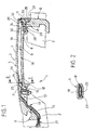
- Figure 1 shows a section, with parts removed for clarity, of a preferred embodiment of the handle according to the present invention;
- Figure 2 shows a section along line II-II in Figure 1;
- Figure 3 shows an exploded view in perspective of a detail of Figure 1;
- Figure 4 shows a view in perspective of a variation of the Figure 3 detail.
- Number 1 in Figure 1 indicates as a whole a handle for a vehicle door not shown.
- Handle 1 comprises a
fastening structure 2, which is connected integrally in known manner, not described in detail, to the door (not shown); and alever 3 for controlling a lock (not shown) on the door. -
Lever 3 comprises an end portion 4 hinged tostructure 2, in known manner not described in detail, to move, with respect tostructure 2, to and from an extracted position to activate the lock (not shown).Lever 3 also comprises a hollow, elongated,intermediate portion 5, which is gripped manually, in use, by a user; and anend portion 6, opposite portion 4, which extends throughstructure 2 and is connected to the door lock (not shown). -
Intermediate portion 5 comprises a longitudinal front wall 7 facing, in use, the user and defined internally by aninner surface 7a; and arear wall 8 facing front wall 7 and adjacent, in use, to the body of the door. Together with the rest oflever 3,walls 7 and 8 define an elongated cavity 9 communicating with the outside through two facingend openings Opening 11 extends throughend portion 6; opening 12 comes out inside afurther cavity 13 formed in portion 4; andcavity 13 is closed partly by acover 14 to define achamber 15, and a conduit orpassage 16 connectingchamber 15 to the outside. - A known detecting
device 18 is housed radially loosely inside elongated cavity 9, and, in the particular example described, comprises a hollowouter casing 19 formed in one piece or by two connected half-shells, and an antenna orsensor 20 locked insidecasing 19 and connected towiring 21.Wiring 21 comes out of anend portion 23, adjacent tochamber 15, ofcasing 19, and extends outside throughchamber 15 and passage 16 (Figure 1). - As shown in Figure 1 and particularly in Figure 2,
end portion 23 ofcasing 19 is connected tointermediate portion 5 by ananchoring device 24 comprising an annular, convenientlyelastic body 25 partly surroundingend portion 23 and which is forced inside cavity 9 to form ahinge enabling casing 19 to rotate to and from wall 7. - As shown in Figure 1,
casing 19 is pushed againstsurface 7a of wall 7 by anelastic device 28 interposed betweenwall 8 and anend portion 26,opposite portion 23, ofcasing 19. - In the example described and shown in particular in Figures 1 and 3,
device 28 comprises a supportingplate 29 resting on a portion ofwall 8 adjacent toend portion 6 and end opening 11; and an elasticallydeformed lever 30, which is integral withplate 29, forms an acute angle A withplate 29, and terminates with afastening portion 31 resting against an inner surface ofportion 26 facingstructure 2.Portion 31 has twoadjacent holes 32, each engaged by arespective pin 33 integral withcasing 19 and projecting fromcasing 19 parallel to theother pin 33. The portion ofplate 29 opposite the portion integral withlever 30 is connected integrally to acover 35 for closing end opening 11. In the particular example described,cover 35, supportingplate 29, and lever 30 form part of asingle body 36 formed in one piece and connected releasably toportion 6 by a removableretaining pin 37. - In the Figure 4 variation,
plate 29 is separate fromcover 35;lever 30 is connected directly and integrally tocasing 19; andelastic device 28 and casing 19 - or at least part ofcasing 19, if this comprises a number of parts - preferably form part of asingle body 38 formed in one piece. - In actual use,
annular body 25 provides for easily hinging one end of detectingdevice 18 and allowing the rest ofdevice 18 to oscillate, inside cavity 9, to and from wall 7. And, in parallel,elastic device 28forces portion 26 ofcasing 19 elastically against wall 7, so that the efficiency of detectingdevice 18 is in no way impaired by any external force transmitted tointermediate grip portion 5 by the user, or simply by the door being closed sharply, and such as to deformintermediate portion 5. In fact, when such external force is applied,device 18 is free to move, inside cavity 9, with respect toportion 5, upon the external force exceeding the elastic load imparted bydevice 28. In handle 1 described,elastic device 28 therefore makes detectingdevice 18 functionally unaffected by any deformation ofintermediate portion 5, which may therefore be made of any, even flexible or easily deformable material. - In the absence of external force,
device 18 is maintained byelastic device 28 in a stable condition, thus preventing any relative movement resulting in vibration or undesired acoustic emissions. - Forming
elastic device 28 in one piece withcover 35 closing end opening 11 of insertion of detectingdevice 18 reduces the number of component parts, makes assembly faster, and improves the stability of the handle, by the component parts being interconnected so that each maintains its original position. -
Cavity 13 and theparticular cover 14, on the one hand, permit direct access to detectingdevice 18 to connectdevice 18 electrically to wiring 21, if necessary, once detectingdevice 18 is inserted insideintermediate portion 5 oflever 3, and, on the other, define the wiring conduit while greatly simplifying formation of the lever and assembly of the handle. - Clearly, changes may be made to handle 1 as described herein without, however, departing from the scope of the present invention as defined by the appended claims. In particular, a different elastic forcing device may be provided and located in a different position from the one shown by way of example.
-
End portion 23 ofdevice 18 may be connected differently to lever 3, even by means of a further elastic retaining device identical with or differing from the one described. - Moreover, detecting
device 18 may have noouter casing 19, andelastic device 28 and the anchoring device may act directly on the sensor or detectingantenna 20.
Claims (16)
- A handle (1) for a vehicle door, the handle (1) comprising fastening means (2), which are connectable integrally to said door; a grip member (5), which is fitted to said fastening means (2), is gripped in use by a user, and defines an inner cavity (9); and detecting means (18) housed loosely inside said cavity (9); characterized in that said detecting means (18) are maintained inside said cavity (9) by cooperation of- anchoring means (24), connecting a first portion (23) of said detecting means (18) to said grip member (5) in an oscillating manner; and- elastic forcing means (28) acting on a second portion (26), separate from said first portion (23), of said detecting means (18) for keeping said detecting means (18) in contact with a seating surface (7a) in said cavity (9).
- A handle as claimed in Claim 1, characterized in that said first (23) and said second (26) portion are end portions of said detecting means (18).
- A handle as claimed in Claim 1 or 2, characterized in that said anchoring means (24) comprise an elastic member (25) force-fitted inside said cavity (9).
- A handle as claimed in Claim 1 to 3, characterized in that said elastic forcing means (28) act on a surface of said detecting means (18) facing said fastening means (2), to push the detecting means (18) towards an outer front wall (7) of the grip member (5).
- A handle as claimed in any one of the foregoing Claims, characterized in that said cavity (9) has an insertion opening (11) for insertion of said detecting means (18); and in that said elastic forcing means (28) are located close to said insertion opening (11).
- A handle as claimed in Claim 5, characterized by comprising closing means (35) for closing said insertion opening (11); said elastic forcing means (28) being carried by said closing means (35).
- A handle as claimed in Claim 6, characterized in that said closing means comprise a closing member (35); said elastic forcing means (28) and said closing member (35) forming part of a one-piece body (36).
- A handle as claimed in Claim 6 or 7, characterized by comprising releasable further connecting means (32, 33) interposed between said elastic forcing means (28) and said detecting means (18).
- A handle as claimed in Claim 8, characterized in that said further connecting means comprise at least one retaining seat (32) carried by said elastic forcing means (28) or said detecting means (18); and at least one pin (33) carried by the other of said elastic forcing means (28) or said detecting means (18) and engaging said seat (32).
- A handle as claimed in one of Claims 7 to 9, characterized by comprising releasable fastening means (37) for connecting said one-piece body (36) releasably to said grip member (5).
- A handle as claimed in any one of the foregoing Claims, characterized in that said elastic forcing means (28) comprise at least one elastically deformed push lever (30).
- A handle as claimed in one of Claims 1 to 5, characterized in that said detecting means (18) comprise a detecting member (20), and an outer casing (19) housing said detecting member (20); said elastic forcing means (28) acting on said outer casing (19).
- A handle as claimed in Claim 12, characterized in that said elastic forcing means (28) are carried by said outer casing (19).
- A handle as claimed in Claim 13, characterized in that said elastic forcing means (28) comprise at least one elastically deformed lever (30) integral with said outer casing (19).
- A handle as claimed in any one of the foregoing Claims, characterized by comprising a connecting opening (12, 13) connecting the cavity (9) with the outside; said detecting means (18) comprising wiring (21) extending through said connecting opening (12, 13); and plugging means (14) being provided to partly close said connecting opening (12, 13).
- A handle as claimed in Claim 15, characterized in that said plugging means (14) are fitted releasably, and partly define a channel (16) for the passage of said wiring (21).
Priority Applications (7)
| Application Number | Priority Date | Filing Date | Title |
|---|---|---|---|
| DE60129429T DE60129429T2 (en) | 2001-08-16 | 2001-08-16 | Door handle for a motor vehicle |
| AT01830539T ATE367496T1 (en) | 2001-08-16 | 2001-08-16 | DOOR HANDLE FOR A MOTOR VEHICLE |
| EP01830539A EP1284334B1 (en) | 2001-08-16 | 2001-08-16 | Vehicle door handle |
| ES01830539T ES2290106T3 (en) | 2001-08-16 | 2001-08-16 | HANDLE FOR THE DOOR OF A VEHICLE. |
| ES02018336T ES2305163T3 (en) | 2001-08-16 | 2002-08-14 | OPENING HANDLE THAT INCLUDES AN ELECTRONIC MODULE, ESPECIALLY FOR AUTOMOBILE VEHICLE. |
| DE60225978T DE60225978T2 (en) | 2001-08-16 | 2002-08-14 | Door handle with electronic module, especially for motor vehicles |
| EP02018336.4A EP1284335B2 (en) | 2001-08-16 | 2002-08-14 | Door handle incorporating an electronic module, in particular for a vehicle |
Applications Claiming Priority (1)
| Application Number | Priority Date | Filing Date | Title |
|---|---|---|---|
| EP01830539A EP1284334B1 (en) | 2001-08-16 | 2001-08-16 | Vehicle door handle |
Publications (2)
| Publication Number | Publication Date |
|---|---|
| EP1284334A1 EP1284334A1 (en) | 2003-02-19 |
| EP1284334B1 true EP1284334B1 (en) | 2007-07-18 |
Family
ID=8184661
Family Applications (1)
| Application Number | Title | Priority Date | Filing Date |
|---|---|---|---|
| EP01830539A Expired - Lifetime EP1284334B1 (en) | 2001-08-16 | 2001-08-16 | Vehicle door handle |
Country Status (4)
| Country | Link |
|---|---|
| EP (1) | EP1284334B1 (en) |
| AT (1) | ATE367496T1 (en) |
| DE (2) | DE60129429T2 (en) |
| ES (1) | ES2290106T3 (en) |
Families Citing this family (21)
| Publication number | Priority date | Publication date | Assignee | Title |
|---|---|---|---|---|
| JP4342207B2 (en) | 2003-04-22 | 2009-10-14 | アイシン精機株式会社 | Vehicle door handle device |
| JP4052277B2 (en) | 2004-04-19 | 2008-02-27 | アイシン精機株式会社 | Vehicle door handle device |
| US9260882B2 (en) | 2009-03-12 | 2016-02-16 | Ford Global Technologies, Llc | Universal global latch system |
| DE102009057005A1 (en) * | 2009-12-04 | 2011-06-09 | Audi Ag | Door handle for a vehicle door |
| US9551166B2 (en) | 2011-11-02 | 2017-01-24 | Ford Global Technologies, Llc | Electronic interior door release system |
| US9416565B2 (en) | 2013-11-21 | 2016-08-16 | Ford Global Technologies, Llc | Piezo based energy harvesting for e-latch systems |
| US10323442B2 (en) | 2014-05-13 | 2019-06-18 | Ford Global Technologies, Llc | Electronic safe door unlatching operations |
| US10273725B2 (en) | 2014-05-13 | 2019-04-30 | Ford Global Technologies, Llc | Customer coaching method for location of E-latch backup handles |
| US10119308B2 (en) | 2014-05-13 | 2018-11-06 | Ford Global Technologies, Llc | Powered latch system for vehicle doors and control system therefor |
| US9903142B2 (en) | 2014-05-13 | 2018-02-27 | Ford Global Technologies, Llc | Vehicle door handle and powered latch system |
| US9834964B2 (en) * | 2014-05-13 | 2017-12-05 | Ford Global Technologies, Llc | Powered vehicle door latch and exterior handle with sensor |
| US9909344B2 (en) | 2014-08-26 | 2018-03-06 | Ford Global Technologies, Llc | Keyless vehicle door latch system with powered backup unlock feature |
| US9725069B2 (en) | 2015-10-12 | 2017-08-08 | Ford Global Technologies, Llc | Keyless vehicle systems |
| US10550610B2 (en) | 2016-06-22 | 2020-02-04 | Ford Global Technologies, Llc | Inside override emergency handle for door release |
| US10227810B2 (en) | 2016-08-03 | 2019-03-12 | Ford Global Technologies, Llc | Priority driven power side door open/close operations |
| US10087671B2 (en) | 2016-08-04 | 2018-10-02 | Ford Global Technologies, Llc | Powered driven door presenter for vehicle doors |
| US10329823B2 (en) | 2016-08-24 | 2019-06-25 | Ford Global Technologies, Llc | Anti-pinch control system for powered vehicle doors |
| US10458171B2 (en) | 2016-09-19 | 2019-10-29 | Ford Global Technologies, Llc | Anti-pinch logic for door opening actuator |
| US10604970B2 (en) | 2017-05-04 | 2020-03-31 | Ford Global Technologies, Llc | Method to detect end-of-life in latches |
| US10907386B2 (en) | 2018-06-07 | 2021-02-02 | Ford Global Technologies, Llc | Side door pushbutton releases |
| DE112021003406T5 (en) * | 2020-06-24 | 2023-04-27 | Alps Alpine Co., Ltd. | DOOR HANDLE DEVICE |
Family Cites Families (2)
| Publication number | Priority date | Publication date | Assignee | Title |
|---|---|---|---|---|
| JP3648396B2 (en) * | 1998-12-02 | 2005-05-18 | トヨタ自動車株式会社 | Vehicle door handle |
| IT247924Y1 (en) * | 1999-03-12 | 2002-09-16 | Valeo Sicurezza Abitacolo Spa | HANDLE FOR A VEHICLE DOOR. |
-
2001
- 2001-08-16 EP EP01830539A patent/EP1284334B1/en not_active Expired - Lifetime
- 2001-08-16 DE DE60129429T patent/DE60129429T2/en not_active Expired - Lifetime
- 2001-08-16 AT AT01830539T patent/ATE367496T1/en not_active IP Right Cessation
- 2001-08-16 ES ES01830539T patent/ES2290106T3/en not_active Expired - Lifetime
-
2002
- 2002-08-14 DE DE60225978T patent/DE60225978T2/en not_active Expired - Lifetime
Also Published As
| Publication number | Publication date |
|---|---|
| DE60225978D1 (en) | 2008-05-21 |
| DE60225978T2 (en) | 2009-06-04 |
| ATE367496T1 (en) | 2007-08-15 |
| ES2290106T3 (en) | 2008-02-16 |
| EP1284334A1 (en) | 2003-02-19 |
| DE60129429T2 (en) | 2008-04-10 |
| DE60129429D1 (en) | 2007-08-30 |
Similar Documents
| Publication | Publication Date | Title |
|---|---|---|
| EP1284334A1 (en) | Vehicle door handle | |
| US20020029437A1 (en) | Handle structure of an apparatus for opening and closing a window | |
| US6568719B2 (en) | Door opening device, in particular for an electric household appliance door | |
| US6321411B1 (en) | Doorstop device | |
| JP4557561B2 (en) | Door hinge and removable door check device | |
| WO2001051109A8 (en) | Injection device | |
| KR20040058060A (en) | hinge | |
| CA2393576A1 (en) | Chuck-free latch assembly | |
| KR100668886B1 (en) | Hinge structure of car glove box | |
| CN102165550B (en) | Actuating unit | |
| JPH11320472A (en) | Fluid-actuated grasping device | |
| JPH08322614A (en) | Coupling of band member | |
| EP1624139B1 (en) | Door handle device | |
| CN111971484A (en) | Damper device | |
| KR970061535A (en) | Lock mechanism | |
| US12043336B2 (en) | Bicycle frame tube | |
| KR970018857A (en) | Positioning device and method of movable connector | |
| ITVI20010003A1 (en) | SAFETY SYRINGE | |
| US6410870B1 (en) | Pneumatic actuated switch | |
| KR200438588Y1 (en) | Gap holder | |
| WO2002006651A3 (en) | Motor vehicle control device with an integrated pressure switch | |
| JP7459428B2 (en) | Actuator Device | |
| JP2005339880A (en) | Connector terminal structure of switch case | |
| WO2005004530A3 (en) | Locking mechanism for electronics module for hearing instruments | |
| KR200155610Y1 (en) | Butane Gas Container Adapter |
Legal Events
| Date | Code | Title | Description |
|---|---|---|---|
| PUAI | Public reference made under article 153(3) epc to a published international application that has entered the european phase |
Free format text: ORIGINAL CODE: 0009012 |
|
| AK | Designated contracting states |
Designated state(s): AT BE CH CY DE DK ES FI FR GB GR IE IT LI LU MC NL PT SE TR |
|
| AX | Request for extension of the european patent |
Extension state: AL LT LV MK RO SI |
|
| 17P | Request for examination filed |
Effective date: 20030819 |
|
| AKX | Designation fees paid |
Designated state(s): AT BE CH CY DE DK ES FI FR GB GR IE IT LI LU MC NL PT SE TR |
|
| 17Q | First examination report despatched |
Effective date: 20031127 |
|
| GRAP | Despatch of communication of intention to grant a patent |
Free format text: ORIGINAL CODE: EPIDOSNIGR1 |
|
| GRAS | Grant fee paid |
Free format text: ORIGINAL CODE: EPIDOSNIGR3 |
|
| GRAF | Information related to payment of grant fee modified |
Free format text: ORIGINAL CODE: EPIDOSCIGR3 |
|
| GRAA | (expected) grant |
Free format text: ORIGINAL CODE: 0009210 |
|
| AK | Designated contracting states |
Kind code of ref document: B1 Designated state(s): AT BE CH CY DE DK ES FI FR GB GR IE IT LI LU MC NL PT SE TR |
|
| REG | Reference to a national code |
Ref country code: GB Ref legal event code: FG4D |
|
| REG | Reference to a national code |
Ref country code: CH Ref legal event code: EP |
|
| REF | Corresponds to: |
Ref document number: 60129429 Country of ref document: DE Date of ref document: 20070830 Kind code of ref document: P |
|
| REG | Reference to a national code |
Ref country code: IE Ref legal event code: FG4D |
|
| ET | Fr: translation filed | ||
| PG25 | Lapsed in a contracting state [announced via postgrant information from national office to epo] |
Ref country code: NL Free format text: LAPSE BECAUSE OF FAILURE TO SUBMIT A TRANSLATION OF THE DESCRIPTION OR TO PAY THE FEE WITHIN THE PRESCRIBED TIME-LIMIT Effective date: 20070718 Ref country code: PT Free format text: LAPSE BECAUSE OF FAILURE TO SUBMIT A TRANSLATION OF THE DESCRIPTION OR TO PAY THE FEE WITHIN THE PRESCRIBED TIME-LIMIT Effective date: 20071218 Ref country code: FI Free format text: LAPSE BECAUSE OF FAILURE TO SUBMIT A TRANSLATION OF THE DESCRIPTION OR TO PAY THE FEE WITHIN THE PRESCRIBED TIME-LIMIT Effective date: 20070718 |
|
| REG | Reference to a national code |
Ref country code: CH Ref legal event code: PL |
|
| NLV1 | Nl: lapsed or annulled due to failure to fulfill the requirements of art. 29p and 29m of the patents act | ||
| REG | Reference to a national code |
Ref country code: ES Ref legal event code: FG2A Ref document number: 2290106 Country of ref document: ES Kind code of ref document: T3 |
|
| PG25 | Lapsed in a contracting state [announced via postgrant information from national office to epo] |
Ref country code: LI Free format text: LAPSE BECAUSE OF FAILURE TO SUBMIT A TRANSLATION OF THE DESCRIPTION OR TO PAY THE FEE WITHIN THE PRESCRIBED TIME-LIMIT Effective date: 20070718 Ref country code: AT Free format text: LAPSE BECAUSE OF FAILURE TO SUBMIT A TRANSLATION OF THE DESCRIPTION OR TO PAY THE FEE WITHIN THE PRESCRIBED TIME-LIMIT Effective date: 20070718 Ref country code: CH Free format text: LAPSE BECAUSE OF FAILURE TO SUBMIT A TRANSLATION OF THE DESCRIPTION OR TO PAY THE FEE WITHIN THE PRESCRIBED TIME-LIMIT Effective date: 20070718 |
|
| PG25 | Lapsed in a contracting state [announced via postgrant information from national office to epo] |
Ref country code: BE Free format text: LAPSE BECAUSE OF FAILURE TO SUBMIT A TRANSLATION OF THE DESCRIPTION OR TO PAY THE FEE WITHIN THE PRESCRIBED TIME-LIMIT Effective date: 20070718 |
|
| PG25 | Lapsed in a contracting state [announced via postgrant information from national office to epo] |
Ref country code: MC Free format text: LAPSE BECAUSE OF NON-PAYMENT OF DUE FEES Effective date: 20070831 Ref country code: DK Free format text: LAPSE BECAUSE OF FAILURE TO SUBMIT A TRANSLATION OF THE DESCRIPTION OR TO PAY THE FEE WITHIN THE PRESCRIBED TIME-LIMIT Effective date: 20070718 Ref country code: GR Free format text: LAPSE BECAUSE OF FAILURE TO SUBMIT A TRANSLATION OF THE DESCRIPTION OR TO PAY THE FEE WITHIN THE PRESCRIBED TIME-LIMIT Effective date: 20071019 |
|
| PLBE | No opposition filed within time limit |
Free format text: ORIGINAL CODE: 0009261 |
|
| STAA | Information on the status of an ep patent application or granted ep patent |
Free format text: STATUS: NO OPPOSITION FILED WITHIN TIME LIMIT |
|
| 26N | No opposition filed |
Effective date: 20080421 |
|
| PG25 | Lapsed in a contracting state [announced via postgrant information from national office to epo] |
Ref country code: SE Free format text: LAPSE BECAUSE OF FAILURE TO SUBMIT A TRANSLATION OF THE DESCRIPTION OR TO PAY THE FEE WITHIN THE PRESCRIBED TIME-LIMIT Effective date: 20071018 |
|
| PG25 | Lapsed in a contracting state [announced via postgrant information from national office to epo] |
Ref country code: IE Free format text: LAPSE BECAUSE OF NON-PAYMENT OF DUE FEES Effective date: 20070816 |
|
| REG | Reference to a national code |
Ref country code: GB Ref legal event code: 732E Free format text: REGISTERED BETWEEN 20090618 AND 20090624 |
|
| PG25 | Lapsed in a contracting state [announced via postgrant information from national office to epo] |
Ref country code: CY Free format text: LAPSE BECAUSE OF FAILURE TO SUBMIT A TRANSLATION OF THE DESCRIPTION OR TO PAY THE FEE WITHIN THE PRESCRIBED TIME-LIMIT Effective date: 20070718 |
|
| PG25 | Lapsed in a contracting state [announced via postgrant information from national office to epo] |
Ref country code: LU Free format text: LAPSE BECAUSE OF NON-PAYMENT OF DUE FEES Effective date: 20070816 |
|
| PG25 | Lapsed in a contracting state [announced via postgrant information from national office to epo] |
Ref country code: TR Free format text: LAPSE BECAUSE OF FAILURE TO SUBMIT A TRANSLATION OF THE DESCRIPTION OR TO PAY THE FEE WITHIN THE PRESCRIBED TIME-LIMIT Effective date: 20070718 |
|
| REG | Reference to a national code |
Ref country code: FR Ref legal event code: TP |
|
| REG | Reference to a national code |
Ref country code: GB Ref legal event code: 732E Free format text: REGISTERED BETWEEN 20160317 AND 20160323 |
|
| REG | Reference to a national code |
Ref country code: FR Ref legal event code: PLFP Year of fee payment: 16 |
|
| REG | Reference to a national code |
Ref country code: ES Ref legal event code: PC2A Owner name: U-SHIN ITALIA S.P.A. Effective date: 20160914 |
|
| REG | Reference to a national code |
Ref country code: DE Ref legal event code: R082 Ref document number: 60129429 Country of ref document: DE Representative=s name: PRINZ & PARTNER MBB PATENTANWAELTE RECHTSANWAE, DE Ref country code: DE Ref legal event code: R081 Ref document number: 60129429 Country of ref document: DE Owner name: U-SHIN ITALIA S.P.A., IT Free format text: FORMER OWNER: VALEO S.P.A., SANTENA, TORINO, IT |
|
| REG | Reference to a national code |
Ref country code: FR Ref legal event code: PLFP Year of fee payment: 17 |
|
| REG | Reference to a national code |
Ref country code: FR Ref legal event code: PLFP Year of fee payment: 18 |
|
| PGFP | Annual fee paid to national office [announced via postgrant information from national office to epo] |
Ref country code: DE Payment date: 20200806 Year of fee payment: 20 Ref country code: ES Payment date: 20200910 Year of fee payment: 20 Ref country code: GB Payment date: 20200820 Year of fee payment: 20 Ref country code: FR Payment date: 20200831 Year of fee payment: 20 |
|
| PGFP | Annual fee paid to national office [announced via postgrant information from national office to epo] |
Ref country code: IT Payment date: 20200813 Year of fee payment: 20 |
|
| REG | Reference to a national code |
Ref country code: DE Ref legal event code: R071 Ref document number: 60129429 Country of ref document: DE |
|
| REG | Reference to a national code |
Ref country code: GB Ref legal event code: PE20 Expiry date: 20210815 |
|
| PG25 | Lapsed in a contracting state [announced via postgrant information from national office to epo] |
Ref country code: GB Free format text: LAPSE BECAUSE OF EXPIRATION OF PROTECTION Effective date: 20210815 |
|
| REG | Reference to a national code |
Ref country code: ES Ref legal event code: FD2A Effective date: 20211202 |
|
| PG25 | Lapsed in a contracting state [announced via postgrant information from national office to epo] |
Ref country code: ES Free format text: LAPSE BECAUSE OF EXPIRATION OF PROTECTION Effective date: 20210817 |