EP1284150B1 - Verfahren und Vorrichtung zur Regelung von Spitzenströmen in einer medizinischen Vorrichtung - Google Patents
Verfahren und Vorrichtung zur Regelung von Spitzenströmen in einer medizinischen Vorrichtung Download PDFInfo
- Publication number
- EP1284150B1 EP1284150B1 EP02255449A EP02255449A EP1284150B1 EP 1284150 B1 EP1284150 B1 EP 1284150B1 EP 02255449 A EP02255449 A EP 02255449A EP 02255449 A EP02255449 A EP 02255449A EP 1284150 B1 EP1284150 B1 EP 1284150B1
- Authority
- EP
- European Patent Office
- Prior art keywords
- defibrillation
- parameter
- patient
- expected device
- circuitry
- Prior art date
- Legal status (The legal status is an assumption and is not a legal conclusion. Google has not performed a legal analysis and makes no representation as to the accuracy of the status listed.)
- Expired - Lifetime
Links
- 238000000034 method Methods 0.000 title claims description 55
- 230000004044 response Effects 0.000 claims description 11
- 230000008878 coupling Effects 0.000 claims description 7
- 238000010168 coupling process Methods 0.000 claims description 7
- 238000005859 coupling reaction Methods 0.000 claims description 7
- 230000003287 optical effect Effects 0.000 claims description 5
- 230000008569 process Effects 0.000 description 21
- 238000013461 design Methods 0.000 description 19
- 238000005259 measurement Methods 0.000 description 18
- 238000012360 testing method Methods 0.000 description 13
- 230000006870 function Effects 0.000 description 11
- 230000035939 shock Effects 0.000 description 8
- 239000003990 capacitor Substances 0.000 description 7
- 230000008901 benefit Effects 0.000 description 6
- 238000012545 processing Methods 0.000 description 6
- 238000004891 communication Methods 0.000 description 4
- 238000004590 computer program Methods 0.000 description 4
- 230000001105 regulatory effect Effects 0.000 description 4
- 208000010496 Heart Arrest Diseases 0.000 description 3
- 238000012938 design process Methods 0.000 description 3
- 238000010586 diagram Methods 0.000 description 3
- 230000000694 effects Effects 0.000 description 3
- 210000002064 heart cell Anatomy 0.000 description 3
- 206010061592 cardiac fibrillation Diseases 0.000 description 2
- 210000000038 chest Anatomy 0.000 description 2
- 238000004146 energy storage Methods 0.000 description 2
- 230000002600 fibrillogenic effect Effects 0.000 description 2
- 230000028161 membrane depolarization Effects 0.000 description 2
- 238000012986 modification Methods 0.000 description 2
- 230000004048 modification Effects 0.000 description 2
- XUIMIQQOPSSXEZ-UHFFFAOYSA-N Silicon Chemical compound [Si] XUIMIQQOPSSXEZ-UHFFFAOYSA-N 0.000 description 1
- 208000003443 Unconsciousness Diseases 0.000 description 1
- 239000000853 adhesive Substances 0.000 description 1
- 230000001070 adhesive effect Effects 0.000 description 1
- 230000006399 behavior Effects 0.000 description 1
- 230000005540 biological transmission Effects 0.000 description 1
- 230000002051 biphasic effect Effects 0.000 description 1
- 230000000739 chaotic effect Effects 0.000 description 1
- 239000004020 conductor Substances 0.000 description 1
- 230000001276 controlling effect Effects 0.000 description 1
- 230000009977 dual effect Effects 0.000 description 1
- 210000005003 heart tissue Anatomy 0.000 description 1
- 238000002847 impedance measurement Methods 0.000 description 1
- 238000012804 iterative process Methods 0.000 description 1
- 230000007246 mechanism Effects 0.000 description 1
- 239000003607 modifier Substances 0.000 description 1
- 238000011022 operating instruction Methods 0.000 description 1
- 230000002093 peripheral effect Effects 0.000 description 1
- 239000004065 semiconductor Substances 0.000 description 1
- 229910052710 silicon Inorganic materials 0.000 description 1
- 239000010703 silicon Substances 0.000 description 1
- 239000007787 solid Substances 0.000 description 1
- 238000001356 surgical procedure Methods 0.000 description 1
- 230000001360 synchronised effect Effects 0.000 description 1
Images






Classifications
-
- A—HUMAN NECESSITIES
- A61—MEDICAL OR VETERINARY SCIENCE; HYGIENE
- A61N—ELECTROTHERAPY; MAGNETOTHERAPY; RADIATION THERAPY; ULTRASOUND THERAPY
- A61N1/00—Electrotherapy; Circuits therefor
- A61N1/18—Applying electric currents by contact electrodes
- A61N1/32—Applying electric currents by contact electrodes alternating or intermittent currents
- A61N1/38—Applying electric currents by contact electrodes alternating or intermittent currents for producing shock effects
- A61N1/39—Heart defibrillators
- A61N1/3906—Heart defibrillators characterised by the form of the shockwave
-
- A—HUMAN NECESSITIES
- A61—MEDICAL OR VETERINARY SCIENCE; HYGIENE
- A61N—ELECTROTHERAPY; MAGNETOTHERAPY; RADIATION THERAPY; ULTRASOUND THERAPY
- A61N1/00—Electrotherapy; Circuits therefor
- A61N1/18—Applying electric currents by contact electrodes
- A61N1/32—Applying electric currents by contact electrodes alternating or intermittent currents
- A61N1/38—Applying electric currents by contact electrodes alternating or intermittent currents for producing shock effects
- A61N1/39—Heart defibrillators
- A61N1/3925—Monitoring; Protecting
- A61N1/3937—Monitoring output parameters
- A61N1/3943—Monitoring output parameters for threshold determination
Definitions
- the present invention relates, in general, to defibrillation units.
- Defibrillation units have been widely used to administer one or more high-voltage, direct-current shock pulses to a patient experiencing cardiac arrest occurring because of asynchronous depolarization, i.e., fibrillation, of cardiac cells. Unconsciousness and/or death generally follow quickly after cardiac arrest. When sufficient electrical energy is delivered to the heart from a defibrillator through two or more electrodes positioned to engage the patient, fibrillation of the cardiac cells may be arrested. Thereafter, synchronous or normal depolarization of the cardiac cells will often resume.
- defibrillation units There are two basic types of defibrillation units known in the art: external defibrillation units (which generally administer energy to a heart via electrodes placed in proximity to the surface of a patient's body or via electrodes placed on the surface of a heart exposed during open-heart surgery) and internal defibrillation units (which generally administer energy to a heart by electrodes inserted via incisions in a patient's body and subsequent placement of the electrodes either directly in or in extremely close proximity to the patient's heart.)
- external defibrillation units which generally administer energy to a heart via electrodes placed in proximity to the surface of a patient's body or via electrodes placed on the surface of a heart exposed during open-heart surgery
- internal defibrillation units which generally administer energy to a heart by electrodes inserted via incisions in a patient's body and subsequent placement of the electrodes either directly in or in extremely close proximity to the patient's heart.
- FIGURE 1A shown is a pictographic representation of related-art external defibrillation unit 100.
- external electrodes 102, 104 which are typically positioned on a patient's chest in the case of external defibrillation in order to deliver defibrillation energy.
- External defibrillation units e.g., external defibrillation unit 100
- defibrillators are often used in chaotic and stressful environments.
- field use of defibrillators is quite common in which paramedics rush to a scene of a person who has experienced cardiac arrest.
- the probability for accidental misuse can be high and it is not uncommon for the external electrodes (e.g., external electrodes 102 and 104) to come in contact with each other when the defibrillation unit is on and fully charged (defibrillators often store and discharge energy via the use of storage capacitors -devices which condense and store electrical energy), which effectively amounts to an electrical short circuit between the external defibrillation electrodes.
- short-circuit testing typically requires that an external defibrillation unit (e.g., external defibrillation unit 100) be able to withstand a certain number (e.g., ten (10)) of short-circuit discharges from a fully-charged state, where the required number of short-circuit discharges are done in rapid succession.
- an external defibrillation unit e.g., external defibrillation unit 100
- a certain number e.g., ten (10)
- FIGURE 1B shown is a pictographic representation of defibrillation unit 100 undergoing short-circuit testing in the context of two graphs 106, 108. Depicted is the little-known fact that the energy which defibrillation unit 100 is set to deliver (such setting done either internally or via controls external to defibrillation unit 100) is actually calibrated (or baselined) against an expected 50 ohm "defibrillation impedance" (defibrillation impedance is a measure of how much the patient itself will impede the delivery of defibrillation energy when viewed at or near the standpoint of the source delivering the defibrillation energy.) As in the case of short-circuit testing, the amount of delivered energy to be used in dosing protocols is specified by defibrillation industry standards.
- the American Heart Association recommends that in adults an energy level of 200 joules be set for the first defibrillation pulse, 200 or 300 joules for a second defibrillation pulse (if the first is unsuccessful), and 360 joules for a third defibrillation pulse (if the second pulse is unsuccessful) -- all of such pulses generally baselined or calibrated for discharge through a 50-ohm defibrillation impedance.
- Illustrated on graph 106 of FIGURE 1B is the fact that if the energy is baselined against 50 ohms of defibrillation impedance (i.e., the unit is charged to a voltage which will deliver the specified energy into 50 ohms, e.g., graph 108), then extremely high levels of current will result within defibrillation unit 100 when defibrillation unit 100 undergoes short-circuit testing. These high levels of current are far in excess of that needed to defibrillate. The extremely high levels of current cause great strain on the electrical components of defibrillation unit 100, and can cause failure of such components.
- defibrillation unit 100 e.g., defibrillation unit 100
- defibrillation unit 100 have generated a solution to the problems associated with the extremely high current discharges and associated electrical component stresses depicted and described in relation to FIGURE 1B.
- FIGURE 1C shown is a related-art solution to the problems depicted and described in relation to FIGURE 1B.
- defibrillation unit makers have had little choice in adjusting the amount of energy to be delivered into a 50 ohm impedance.
- a defibrillation unit 110 which is essentially defibrillation unit 100 modified to have high-current electrical components sufficient to withstand the extremely high short-circuit testing discharges depicted and described in relation to graph 106 of FIGURE 1B.
- the present invention allows defibrillation units to consistently meet regulatory-agency-required short-circuit testing while simultaneously meeting various industry-standards related to required amounts of defibrillation energy (e.g., 360 Joules) in such a way that the unnecessarily high current electrical components of the related art are no longer necessary.
- a method comprising: measuring a patient parameter associated with a human body; in response to the patient parameter, retrieving a maximum expected device parameter; and setting a limit on an energy source such that during defibrillation of the patient a defibrillation parameter associated with the maximum expected device parameter is within a defined tolerance; wherein said retrieving a maximum expected device parameter comprises: locating the patient parameter on at least one curve associated with a defined prediction confidence lever, where such curve correlates the patient parameter with a predicted maximum expected device parameter; and retrieving a predicted maximum expected device parameter from the at least one curve.
- a system comprising: circuitry for measuring a patient parameter associated with a human body; circuitry, responsive to the patient parameter, for retrieving a maximum expected device parameter; and circuitry for setting a limit on an energy source such that during defibrillation of the patient a defibrillation parameter associated with the maximum expected device parameter is within a defined tolerance; wherein said circuitry for retrieving a maximum expected device parameter comprises: circuitry for locating the patient parameter on at least one curve correlates the patient parameter with a predicted maximum expected device parameter; and circuitry for retrieving a predicted maximum expected device parameter from the at least one curve.
- the related-art solution to the requirement that defibrillation units pass regulatory-agency-required short-circuit testing is to introduce into defibrillation units high-power electrical components sufficient to stand the stress that results from the short-circuit testing.
- the inventors have discovered a way to construct defibrillation units which supply industry-required levels of defibrillation energy and which will survive the short circuit testing described in the background section above, but which can do the foregoing via the use of much-lower-power components than commonly utilized in the related art.
- the inventors' solution provides performance substantially comparable to related-art defibrillation units, but does so in a way in which defibrillation units can be constructed from much cheaper components than those utilized in the related-art defibrillation units.
- the techniques described herein will stress electrical components much less than that generally required in the related art, which will generally lead to higher reliability of such components.
- maximum-rated electrical current will be described herein for sake of illustration, those having ordinary skill in the art will recognize that electrical components often have absolute maximum ratings for several parameters, such as power, current, and voltage; accordingly, although the present discussion describes current as the parameter of interest, those having ordinary skill in the art will recognize that such discussion can be generalized to other like parameters without undue experimentation.
- the present invention may be applied to any defibrillation unit components associated with such parameters, such components only depending on the particular circuit topology of the unit.
- defibrillation unit components associated with such parameters, such components only depending on the particular circuit topology of the unit.
- such components may include the electrical components of an H-Bridge discharge circuit, e.g., silicon controlled rectifiers and/or insulated gate bipolar transistors, and their respective connectors and wires.
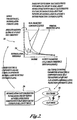
- FIGURE 2 shown is a design process which the inventors have devised which provides the foregoing-referenced benefits, as well as other benefits which will be apparent to those having ordinary skill in the art.
- the inventors' solution makes use of an "iterative" design strategy which gives great flexibility to defibrillation unit system designers.
- a defibrillation unit designer can specify certain types of electrical components which the designer would prefer to use in defibrillation unit 200.
- the system designer may use the defined tolerances of the electrical components specified (those having ordinary skill in the art will recognize that most electrical components have defined operating characteristics where their performance is substantially guaranteed) to determine the absolute upper limit of some device parameter (e.g., electrical current) at which defibrillation unit 200 can be expected to reliably operate.
- some device parameter e.g., electrical current
- this component-specified operating limit i.e., the upper limit on some electrical parameter, such as current
- this component-specified operating limit can be used with a family of curves, such as those shown on graph 202, to determine an impedance at which it can be said with a percentage confidence that substantially all of patients encountered will be successfully defibrillated utilizing the defined electrical components of defibrillation unit 200.
- graph 202 of FIGURE 2 shows that the design parameter of interest is defibrillation current
- the "iterative" design strategy employed herein could be utilized for other design parameters, such as voltage, or time.
- defibrillation current is discussed herein as the design parameter of interest.
- the lower curve 208 is above the defibrillation threshold, then it can be determined that patients will be defibrillated at least to the confidence prediction level of the curves 208, 210. For example, if the curves 208, 210 represent the 99.9% prediction confidence levels, and if the lower curve is above the defibrillation threshold, then it can be determined with more than 99.9% confidence that patients will be defibrillated by a unit having the specified electrical components.
- the defibrillation prediction confidence level which can be generated with the chosen electrical components for defibrillation unit 200 is not substantially optimal (e.g., the behavior is substantially optimal when the region defined and/or bracketed by curves 208, 210 is above the defibrillation threshold)
- family of curves 208, 210 of graph 202 can be used to determine the substantially minimum device parameter (e.g., current) characteristics necessary to also insure that the patients will be defibrillated to the specified confidence level.
- the system designer can utilize such defined device parameter characteristics to select a new set of electrical components for defibrillation unit 200, such that the defibrillation unit 200 is substantially ensured to defibrillate at the desired defibrillation prediction confidence level at a lower (or lowest) cost of electrical components, at least insofar as the device parameter characteristic or characteristics of interest are concerned.
- the inventors' "iterative" design scheme allows great flexibility in the design of defibrillation units in that a system designer can (1) specify the electrical components the system designer desires to use, (2) determine if such specified electrical components will give acceptable prediction confidence levels with respect to patients to be defibrillated, and, if not, (3) thereafter utilize a family of curves such as those illustrated in graph 202 to determine adjustments necessary to the system-designer-chosen components such that the defibrillation threshold is exceeded to a prediction confidence level deemed adequate.
- the system designer will have to choose electrical components with increased ratings; that is, in some instances the system designer may determine that the chosen electrical components exceed the defibrillation threshold to a greater prediction confidence level than the system designer deems necessary, in which case the system designer can specify electrical components with progressively lower ratings (e.g., absolute maximum current ratings) and engage in the iterative process shown in FIGURE 2 while the electrical components of the defibrillation unit 200 have ratings in excess of the defibrillation threshold to a prediction confidence level specified by the system designer.
- progressively lower ratings e.g., absolute maximum current ratings
- the inventors' scheme of defibrillation design illustrated in FIGURE 2 gives great flexibility in the design of defibrillation units in that it allows a designer to either (a) begin with a set of electrical components and engage in iterative computational/analytical design to rapidly reach acceptable electrical component specification, or (b) begin with a specified prediction confidence level of successful defibrillation and use the defibrillation prediction confidence level of given curves (e.g., current 208, 210), to define the substantially optimal device parameters related to the electrical components of defibrillation unit 200.
- a specified prediction confidence level of successful defibrillation and use the defibrillation prediction confidence level of given curves e.g., current 208, 210
- the inventors' iterative design scheme described herein completely reverses that utilized in the related art. That is, rather than defining certain levels of energy to be delivered to a prespecified load, and then "beefing up" the electrical components of a defibrillation unit to withstand a short-circuit, the inventors' scheme allows either (a) the electrical components or (b) a defibrillation prediction confidence level to be specified first, and such electrical components or defibrillation prediction confidence level to be thereafter utilized with the iterative scheme in order to determine the electrical components desired/necessary . Thus, the inventors' scheme inverts the method of the related art and hence, represents a significant advance in the design of defibrillation units.
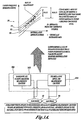
- FIGURE 3A shown is an example of one way in which a family of curves, such as curves 208, 210 depicted in graph 202, can be constructed.
- the desired amount of energy to be delivered to patients in order to successfully defibrillate patients has been specified by various regulatory agencies, and this energy relationship is used to define the curves shown in graph 202 of FIGURE 2.
- the family of curves of graph 202 has associated with them defibrillation prediction confidence levels. These defibrillation prediction confidence levels are empirically generated via use of the process shown and described in FIGURE 3A.
- defibrillation unit 300 Shown in FIGURE 3A is defibrillation unit 300.
- defibrillation unit 300 Depicted internal to defibrillation unit 300 are energizing and patient parameter measurement circuitry 302 and defibrillation shock and measurement circuitry 304, both of which are electrically connected with electrodes 102 and 104 via engineering techniques well known to those having ordinary skill in the art. Illustrated is that electrodes 102 and 104 are in contact with a human body which appears to the energizing and patient parameter measurement circuitry 302 to have an impedance with both a resistive and a reactive part, and which appears to the defibrillation shock and measurement circuitry 304 to have a primarily resistive impedance.
- defibrillation unit 300 is used to gather empirical data by engaging in multiple trials pairing a measured patient parameter against a measured defibrillation impedance.
- energizing and measurement circuitry energizes electrodes 102 and 104 with a 62.5 kilohertz time-varying voltage signal, and thereafter measures the impedance of the human body generated in response to the 62.5 kilohertz time-varying voltage signal.
- defibrillation shock and measurement circuitry 304 discharges a defibrillation pulse into the human body and utilizes well-known techniques drawn on the defibrillation energy discharged into the human body in order to determine a defibrillation impedance (e.g., see United States Patent 5,999,852, "Defibrillation Method and Apparatus” incorporated herein by reference, and refer to the description of patient TTI (transthoracic impedance) measured during delivery of a defibrillation pulse).
- a defibrillation impedance e.g., see United States Patent 5,999,852, "Defibrillation Method and Apparatus” incorporated herein by reference, and refer to the description of patient TTI (transthoracic impedance) measured during delivery of a defibrillation pulse.
- CFI carrier frequency impedance
- a best fit curve fitting algorithm e.g., a least mean squares curve fitting algorithm
- a best fit curve fitting algorithm may be employed to draw a "best fit" curve through the data (e.g., line 312 of FIGURE 3A).
- pairs of curves e.g., curves 308 and 310 may be drawn about the best fit curve (illustrated as curve 312).
- statistical techniques e.g., statistical inference
- this maneuver is illustrated graphically and mathematically in FIGURE 3B. Notice that this maneuver is counter-intuitive in that while ultimately it will be the defibrillation impedance axis which is utilized to construct confidence interval curves, it is against the carrier frequency impedance axis that the statistical inference distribution is baselined, which is somewhat surprising in that it essentially reverses the ordinary line of thought typically utilized by those having ordinary skill in the art.
- the various defibrillation current curves of graph 202 can be associated with prediction confidence levels.
- the 95% impedance prediction confidence level defined by curve 308 of FIGURE 3A is associated with curve 210 of FIGURE 2.
- the designer can be greater than 95% certain that a patient at the specified defibrillation impedance will be defibrillated.
- FIGURE 3B shows an empirically generated data set and one implementation of equations utilized to derive impedance prediction confidence intervals shown therein.
- one aspect of the generation of impedance prediction confidence intervals is that the way in which they are generated and/or used herein goes “against the grain” of the way in which those skilled in the art are typically taught to generate and use such intervals.
- FIGURE 3B shows an actual empirical data set along with actual mathematical equations utilized to generate the impedance prediction confidence intervals shown thereon.
- FIGURE 3A While the explanation of FIGURE 3A is sufficient to teach how to generate the confidence intervals without undue experimentation, the inventors have chosen to include FIGURE 3B as a specific example of the more general case described in relation to FIGURE 3A so that those skilled in the art will be able to generate and use the impedance prediction confidence intervals shown and described herein with much less experimentation than ordinarily is required in the art.
- defibrillation unit 200 allows design of defibrillation unit 200 with much lower current components than those necessary in the related art.
- a designer would preferably set the defibrillation energy source (e.g., a capacitor, bank of capacitors or other DC source) of defibrillation unit 200 to a voltage level such that defibrillation current discharged into a patient tracks the defined defibrillation prediction confidence a predicted-level curve family of graph 202 in a fashion such as will now be described.
- the defibrillation energy source e.g., a capacitor, bank of capacitors or other DC source
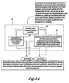
- defibrillation unit 400 which has components functionally analogous to those shown in defibrillation unit 300, plus the addition of defibrillation charging control circuitry 402.
- defibrillation charging control circuitry 402 obtains the carrier frequency impedance measured by energizing and patient parameter measurement circuitry 302 and in response to such obtained carrier frequency impedance directs that defibrillation shock and measurement circuitry 304 set its defibrillation energy source such that a defined level of defibrillation energy will be discharged sufficient to meet whatever defibrillation prediction confidence level the system designer has defined.
- an attempt is made to deliver sufficient energy such that the defibrillation threshold of graph 202 is exceed and the value of the electrical parameter of interest (e.g., current) is not exceeded, so as to prevent damage at least to a specified prediction confidence level, while at the same time meeting the industry standard levels of defibrillation energy.
- the electrical parameter of interest e.g., current
- defibrillation units 400 can be utilized with defibrillation units in order to allow such defibrillation units to provide acceptable levels of defibrillation and pass required short-circuit testing.
- an amount of stored energy in defibrillation unit 400 is adjusted in response to a measured carrier frequency impedance such that current delivered will fall within the bounds of a defined family of curves such as curves 208, 210 shown in graph 202.
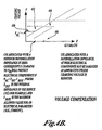
- FIGURE 4B shows an example of one energy adjustment curve based on the foregoing described scheme, where the curve shown in FIGURE 4B is based upon the empirically derived data set and family of curves shown and described in relation to FIGURE 3B.
- defibrillation units often store energy in capacitive structures, and thereafter discharge the energy stored in such capacitive structures into the patient.
- the energy stored in such capacitive structures as well as the maximum defibrillation current can be determined from said voltage and the patient's defibrillation impedance. Accordingly, if the voltage adjustment curve of FIGURE 4B is implemented by defibrillation charging control circuitry 402, then the family of curves in graph 202 can be determined.
- FIGURE 4B One implementation whereby voltage can be adjusted in response to a measured carrier frequency impedance is shown in FIGURE 4B.
- Segment 450 has a constant charging voltage since in this region the associated 95% confidence prediction level of defibrillation impedance is less than zero. Since the defibrillation impedance physically cannot be less than zero, the worse case defibrillation impedance can be assumed to be zero. In this implementation, zero defibrillation impedance will result in 200 amps (the maximum the electrical components of this implementation can accommodate) if the charging voltage is set to that indicated in segment 450. (This is due to an assumed 5 ohms internal impedance.)
- FIGURE Segment 452 shows a voltage compensation region in response to measured carrier frequency impedance.
- Segment 454 shows no voltage compensation such as has been described herein since segment 454 is above defibrillation energy baseline impedance 456 and hence is not the subject of the discussion herein. That is, the resulting current is substantially guaranteed to be below a defined maximum current as indicated by graph 202.
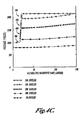
- FIGURE 4C shown is a scaled version of the energy adjustment curve of FIGURE 4B, showing energy storage capacitor voltage for various energies in the 0 to 150 ohm patient-impedance range.
- the voltage compensation region below 21.5 ohms is designed from a linear approximation to the lower 99.9% prediction interval curve of FIGURE 3B, a simplification which has a maximum of 1 volt error.
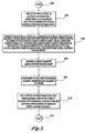
- Block 500 shows the start of the process.
- Block 502 shows forming an electrical circuit via coupling with a human body (e.g., placing external defibrillation electrodes 100, 102 of defibrillation unit 200 onto a human body such as shown and described in relation to FIGURE 4A).
- a human body e.g., placing external defibrillation electrodes 100, 102 of defibrillation unit 200 onto a human body such as shown and described in relation to FIGURE 4A.
- external electrodes is merely exemplary and that the methods and systems described herein can be adapted for use with implantable internal defibrillators via the use of reasonable experimentation well within the ambit of those having ordinary skill in the art.
- Block 504 depicts energizing the electrical circuit formed with the human body via an energy source selected from a group including, but not limited to, a direct current source and an alternating current source.
- the alternating current source has a frequency of 62.5 kilohertz such as was shown and described in relation to the energizing and patient parameter measurement circuitry 302 of FIGURE 4A; however, in other implementations, the alternating current source has frequency of substantially 62.5 kHz, or substantially 20.1 kHz, or substantially 57.1 kHz, and in yet other implementations the alternating current source has a frequency substantially between 1 kHz and 100 kHz.
- Block 506 depicts measuring a patient parameter associated with the human body (e.g., such as energizing and patient parameter measurement circuitry 302 measuring the carrier frequency impedance such as was shown and described in relation to FIGURES 3 and 4).
- Block 508 depicts that in response to the measured patient parameter, a maximum expected device parameter is retrieved (e.g., such as was described in relation to defibrillation charging control circuitry 402 of FIGURE 4A).
- Block 510 shows setting a limit on an energy source (e.g., a defibrillation energy source) such that during defibrillation of the patient a defibrillation parameter associated with the maximum expected device parameter is within a defined tolerance (e.g., attempting to set the energy source such that it will deliver an industry-required amount of defibrillation energy into the highest defibrillation impedance likely to be encountered, but limiting the charging such that at the minimum impedance likely to be encountered at the defined confidence level, a defined circuit parameter of interest is not likely to be exceeded, such as was shown and described in relation to FIGURES 4A, 4B and 4C).
- Block 512 shows the end of the process.
- FIGURE 6 shown is an implementation of the high-level logic flowchart of FIGURE 5, wherein it is shown that in one embodiment of method 506 the measured patient parameter is selected from the patient-parameter group including, but not limited to, a resistance, a reactance, a combination of resistance and reactance, voltage, skin temperature, moisture, motion, and optical properties, and pH; that is, the implementation of FIGURE 6 shows that the carrier frequency impedance measured can include both reactive and resistive parts of the carrier frequency impedance either taken alone or in combination, and that other manners of measuring patient parameters are also contemplated.
- the remaining blocks of FIGURE 6 function substantially as described elsewhere above.
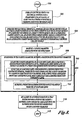
- FIGURE 7 shown is an implementation of the high-level logic flowchart shown in FIGURE 5.
- Block 700 shows that in one implementation retrieving a maximum expected device parameter can include, but is not limited to, locating the patient parameter on at least one curve associated with a defined prediction confidence level, where such curve correlates the patient parameter to a predicted maximum expected device parameter (e.g., locating a patient parameter on the graph of FIGURE 2).
- Block 702 shows retrieving a predicted maximum expected device parameter from the at least one curve (e.g., locating at least one value on curve 210 of FIGURE 2).
- the remaining blocks of FIGURE 7 function substantially as described elsewhere herein.
- FIGURE 8 shown is an implementation of the high-level logic flowchart shown in FIGURE 7. Depicted is an implementation wherein block 700 is shown to include sub-block 800 of selecting the at least one curve associated with a defined prediction confidence interval, where such curve correlates the patient parameter to a maximum expected device parameter, to be a curve whose associated prediction confidence level most closely matches a defined prediction confidence level -- in one implementation, this is achieved by accessing one of a family of curves analogous to those shown and described in relation to graph 202.
- the remaining blocks of FIGURE 8 function substantially as described elsewhere herein.
- the associated prediction confidence level of block 900 includes a statistical inference of a variance of an empirically-generated data set which falls within a region baselined about a curve generated by a curve-fitting algorithm applied to the empirically generated data set (e.g., such as was shown and described in relation to FIGURES 3A and 3B, above). As shown and described in relation to FIGURES 3A and 3B, in one implementation this is achieved via a statistical inference of an empirically-generated data set which falls within a region baselined about a curve which has a relatively smallest least mean squares error, or least absolute error, relative to the empirically generated data set.
- the remaining blocks of FIGURE 9 function substantially in as described elsewhere herein.
- block 510 can include setting an upper limit on the energy source such that at least one defined electrical component is not damaged (e.g., setting a limit on the energy source such that during defibrillation of the patient a maximum expected defibrillation current is within a defined tolerance), such as was discussed in relation to FIGURES 4A, 4B and 4C above, where an attempt is made to set the source such that the person with the highest likely impedance to be encountered will still receive sufficient current to defibrillate while also at the lowest likely impedance to be encountered, a defined absolute maximum of an electrical component of a defibrillation unit (e.g., current of defibrillation unit 200) is not exceeded, all while maintaining the industry standard level of defibrillation energy.
- the remaining blocks of FIGURE 10 function substantially as described elsewhere herein.
- block 1000 of FIGURE 10 can include block 1100 and block 1102.
- Block 1100 shows computing a maximum expected device parameter using a defibrillation source value calculated to provide a specified output defibrillation energy into a defibrillation-unit baseline impedance (e.g., wherein the defibrillation-unit baseline impedance has a value of 50 ohms).
- Block 1102 shows setting an upper limit on the defibrillation source such that the defibrillation parameter associated with the maximum expected device parameter does not exceed the absolute maximum rating of the at least one electrical component, if the computed maximum expected device parameter exceeds an absolute maximum rating of at least one electrical component.
- the remaining blocks of FIGURE 11 function substantially as described elsewhere herein.
- Block 1200 depicts that, in response to the measured patient parameter, a minimum expected device parameter is retrieved.
- Block 1202 illustrates setting a limit on an energy source such that during defibrillation of the patient a defibrillation parameter associated with the minimum expected device parameter is within a defined tolerance (e.g., set a limit on the energy source such that during defibrillation a current is within a defined tolerance).
- the remaining blocks of FIGURE 12 function substantially as described elsewhere herein.
- block 1202 can include setting a lower limit on the energy source such that the defibrillation parameter associated with the minimum expected device parameter exceeds a defibrillation threshold (e.g., such as was discussed in relation to FIGURES 4A, 4B and 4C above, where an attempt is made to set the source such that the person with the highest likely impedance to be encountered will still receive sufficient current to defibrillate while also at the lowest likely impedance to be encountered a defined absolute maximum of an electrical component of a defibrillation unit (e.g., current of defibrillation unit 200) is not exceeded, all while maintaining the industry standard level of defibrillation energy).
- a defibrillation threshold e.g., such as was discussed in relation to FIGURES 4A, 4B and 4C above, where an attempt is made to set the source such that the person with the highest likely impedance to be encountered will still receive sufficient current to defibrillate while also at the lowest likely impedance to be
- block 1300 of FIGURE 13 can include block 1400 and block 1402.
- Block 1400 shows computing a minimum expected device parameter using a defibrillation source value calculated to provide a specified output defibrillation energy into a defibrillation-unit baseline impedance (e.g., wherein the defibrillation-unit baseline impedance has a value of 50 ohms).
- Block 1402 shows setting a lower limit on the defibrillation source such that the defibrillation parameter associated with the minimum expected device parameter is at or above the defibrillation threshold, if the computed minimum expected device parameter is less than the defined defibrillation threshold.
- the remaining blocks of FIGURE 14 function substantially as described elsewhere herein.
- Examples of a signal bearing media include but are not limited to the following: recordable type media such as Random Access Memory (RAM), flash memory, floppy disks, hard disk drives, CD ROMs, digital tape, and transmission type media such as digital and analogue communication links using TDM or IP based communication links (e.g., packet links).
- recordable type media such as Random Access Memory (RAM), flash memory, floppy disks, hard disk drives, CD ROMs, digital tape
- transmission type media such as digital and analogue communication links using TDM or IP based communication links (e.g., packet links).
- electrical circuitry includes but is not limited to electrical circuitry having at least one discrete electrical circuit, electrical circuitry having at least one integrated circuit, electrical circuitry having at least one application specific integrated circuit, electrical circuitry forming a general purpose computing device configured by a computer program (e.g., a general purpose computer configured by a computer program which at least partially effects a process(es) describer herein, or a microprocessor configured by a computer program which at least partially effects a process(es) described herein), electrical circuitry forming a memory device (e.g., any and all forms of data processing memory), and electrical circuitry forming a communications device (e.g., a modem, communications switch, or optical-electrical equipment).
- a computer program e.g., a general purpose computer configured by a computer program which at least partially effects a process(es) describer herein, or a microprocessor configured by a computer program which at least partially effects a process(es) described herein
- FIGURE 13, 14, and 15 show example representations of a processor-based defibrillation unit into which the described devices and/or processes may be integrated with a reasonable amount of experimentation.
- FIGURE 13, 14, and 15 show example representations of a processor-based defibrillation unit into which the described devices and/or processes may be integrated with a reasonable amount of experimentation.
- implementations of devices and processes described herein are not limited to such implementations since, as has been explained above, the state of the art is now such that processes or devices can be implemented in virtually any combination of hardware, software, or firmware.
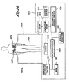
- FIGURE 15 a pictorial representation of a processor-based system is depicted with which illustrative embodiments of the devices and/or processes described herein may be implemented via virtually any combination of software, hardware, and firmware with only minimal experimentation by those having ordinary skill in the art.
- a graphical user interface systems e.g., Microsoft Windows 98 or Microsoft Windows NT operating systems
- Defibrillation unit 200 is depicted which includes data processing system 1520 (which is intended to be exemplary of virtually any processor based system).
- Data processing system 200 includes a system unit housing 1522, video display device 1524, keyboard 1526, a mouse (not shown), and a microphone (not shown).
- Data processing system 1520 is shown interfacing with and controlling energizing and parameter measurement circuitry 302 and defibrillation shock and measurement circuitry 304 in accordance with the teachings herein via techniques notorious within the art.
- Data processing system 1520 may be implemented utilizing any suitable computer such as a DELL® portable computer system, a product of Dell Computer Corporation, located in Round Rock, Texas; Dell is a trademark of Dell Computer Corporation.
- Energizing and patient parameter measurement circuitry 302 and defibrillation shock and measurement circuitry 304 may be implemented utilizing circuitry produced by vendors well known to those having ordinary skill in the art such as Fairchild Semiconductor (e.g., their 74HC74, Dual D Flip Flop), Analog Devices (e.g., their AD8602DRM, Operational Amplifier), Vishay Dale Electronics (e.g., their Thick Film Surface Mount Resistor).
- Fairchild Semiconductor e.g., their 74HC74, Dual D Flip Flop
- Analog Devices e.g., their AD8602DRM, Operational Amplifier
- Vishay Dale Electronics e.g., their Thick Film Surface Mount Resistor
- the defibrillation unit 1610 includes impedance measuring circuit 1611, switch 1613, capacitor bank 1615, energy dump 1616, energy source 1617, defibrillator control circuit 1619, memory 1621, microprocessor 1623, energy selector 1625, and patient electrodes 1627a and 1627b.
- the patient electrodes 1627a and 1627b may be hand-held electrode paddles or adhesive electrode pads placed on the skin of a patient.
- the patient's body or heart provides an electrical path between the electrodes.
- the defibrillator or operating instructions preferably prompt the operator to hold and retain the paddles firmly on the patient's thorax throughout the impedance measurement and defibrillation procedure of the present invention.
- the energy selector 1625 supplies energy setting information to the microprocessor 1623 and instructs the defibrillator regarding the defibrillation pulse energy to be delivered to a patient. While the energy selector 1625 can be in the form of a continuous dial, in a preferred embodiment the energy selector 1625 permits selection of an energy level from a set number of discrete energy levels, such as 100 joules, 200 joules, 300 joules, and 360 joules, for example. If desired, such as in the case of an automated external defibrillator with preprogrammed energy levels, the energy selector 25 could be eliminated, and replaced by pre-programmed levels.
- the patient electrodes 1627a and 1627b are connected to the switch 1613 via conductors 1631a and 1631b.
- the switch 1613 couples the electrodes 1627a and 1627b to either the input of the impedance measuring circuit 1611 or to the output of the capacitor bank 1615, based on the state of a control signal received from the microprocessor 1623.
- the switch is of conventional design and may be formed of electrically-operated relays or solid state devices.
- FIGURE 15, and 16 may vary for specific applications.
- peripheral devices such as optical disk media, audio adapters, video cameras such as those used in videoconferencing, or programmable devices, such as PAL or EPROM programming devices well-known in the art of computer hardware, and the like may be utilized in addition to or in place of the hardware already depicted.
- any two components herein combined to achieve a particular functionality can be seen as “associated with” each other such that the desired functionality is achieved, irrespective of architectures or intermedial components.
- any two components so associated can also be viewed as being “operably connected,” or “operably coupled,” to each other to achieve the desired functionality.
Landscapes
- Health & Medical Sciences (AREA)
- Cardiology (AREA)
- Heart & Thoracic Surgery (AREA)
- Engineering & Computer Science (AREA)
- Biomedical Technology (AREA)
- Nuclear Medicine, Radiotherapy & Molecular Imaging (AREA)
- Radiology & Medical Imaging (AREA)
- Life Sciences & Earth Sciences (AREA)
- Animal Behavior & Ethology (AREA)
- General Health & Medical Sciences (AREA)
- Public Health (AREA)
- Veterinary Medicine (AREA)
- Electrotherapy Devices (AREA)
Claims (34)
- Verfahren, umfassend:dadurch gekennzeichnet, dass die Ermittlung des erwarteten Maximalvorrichtungsparameters Folgendes umfasst:das Messen eines einem menschlichen Körper zugeordneten Patientenparameters;das Ermitteln eines erwarteten Maximalvorrichtungsparameters als Reaktion auf den Patientenparameter; unddas Festsetzen eines Grenzwerts für eine Energiequelle, sodass bei der Defibrillation des Patienten ein dem erwarteten Maximalvorrichtungsparameter zugeordneter Defibrillationsparameter innerhalb eines definierten Toleranzbereichs liegt;das Auffinden des Patientenparameters auf zumindest einer einem definiertem Vorhersagevertrauenswert zugeordneten Kurve, wobei diese Kurve den Patientenparameter mit einem vorhergesagten erwarteten Maximalvorrichtungsparameter korreliert; unddas Ermitteln eines vorhergesagten erwarteten Maximalvorrichtungsparameter aus dieser zumindest einen Kurve.
- Verfahren nach Anspruch 1, weiters umfassend:das Messen eines einem menschlichen Körper zugeordneten Patientenparameters durch die Bildung eines elektrischen Schaltkreises mit einem menschlichen Körper über eine elektrische Kopplung mit einem menschlichen Körper.
- Verfahren nach Anspruch 2, worin das Messen eines einem menschlichen Körper zugeordneten Patientenparameters durch die Bildung eines elektrischen Schaltkreises mit dem menschlichen Körper über eine elektrische Kopplung mit einem menschlichen Körper Folgendes umfasst:die Beaufschlagung des elektrischen Schaltkreises mit Energie über eine Energiequelle, die aus einer eine Gleichstromquelle und eine Wechselstromquelle umfassenden, jedoch nicht auf diese eingeschränkten, Gruppe von Energiequellen ausgewählt ist.
- Verfahren nach Anspruch 3, worin die Wechselstromquelle Folgendes umfasst:eine Wechselstromquelle mit einer Frequenz von im Wesentlichen 62,5 kHz oder im Wesentlichen 20,1 kHz oder im Wesentlichen 57,1 kHz.
- Verfahren nach Anspruch 3, worin die Wechselstromquelle Folgendes umfasst:eine Wechselstromquelle mit einer Frequenz von im Wesentlichen zwischen 1 kHz und 100 kHz.
- Verfahren nach Anspruch 1, worin das Messen eines einem menschlichen Körper zugeordneten Patientenparameters Folgendes umfasst:das Messen eines Patientenparameters, der aus einer Widerstand, Blindwiderstand, eine Kombination aus Widerstand und Blindwiderstand, Spannung, Hauttemperatur, Feuchtigkeit, Bewegung, Farbe, optische Eigenschaften und pH-Wert umfassenden, jedoch nicht darauf eingeschränkten, Gruppe von Patientenparametern ausgewählt ist.
- Verfahren nach Anspruch 1, worin das Auffinden des Patientenparameters auf zumindest einer einem definierten Vorhersagevertrauenswert zugeordneten Kurve, wobei diese Kurve den Patientenparameter mit einem vorhergesagten erwarteten Maximalvorrichtungsparameter korreliert, Folgendes umfasst:das Auswählen der zumindest einen einem definierten Vorhersagevertrauensbereich zugeordneten Kurve, wobei diese Kurve den Patientenparameter mit einem vorhergesagten erwarteten Maximalvorrichtungsparameter korreliert, um eine Kurve zu sein, deren zugeordneter Vorhersagevertrauenswert einem definierten Vorhersagevertrauenswert am besten gleichkommt.
- Verfahren nach Anspruch 7, worin der zugeordnete Vorhersagevertrauenswert Folgendes umfasst:eine statistische Inferenz einer Varianz eines empirisch erzeugten Datensatzes, die in einen Bereich fällt, der um eine als Basislinie dienende Kurve liegt, welche durch einen auf den empirisch erzeugten Datensatz angewendeten Kurvenanpassungsalgorithmus erzeugt wurde.
- Verfahren nach Anspruch 8, worin die statistische Inferenz einer Varianz eines empirisch erzeugten Datensatzes, die in einen Bereich fällt, der um eine als Basislinie dienende Kurve liegt, welche durch einen auf den empirisch erzeugten Datensatz angewendeten Kurvenanpassungsalgorithmus erzeugt wurde, Folgendes umfasst:eine statistische Inferenz einer Varianz eines empirisch erzeugten Datensatzes, die in einen Bereich fällt, der um eine als Basislinie dienende Kurve liegt und der relativ zum empirisch erzeugten Datensatz den relativ kleinsten Fehler, der aus der den kleinsten mittleren quadratischen Fehler und den kleinsten absoluten quadratischen Fehler umfassenden, jedoch nicht darauf eingeschränkten, Gruppe ausgewählt ist, aufweist.
- Verfahren nach Anspruch 1, worin das Festsetzen eines Grenzwerts für die Energiequelle, sodass bei der Defibrillation des Patienten ein dem erwarteten Maximalvorrichtungsparameter zugeordneter Defibrillationsparameter innerhalb eines definierten Toleranzbereichs liegt, Folgendes umfasst:das Festsetzen einer Obergrenze für die Energiequelle, sodass zumindest ein definiertes elektrisches Bauteil nicht beschädigt wird.
- Verfahren nach Anspruch 10, worin das Festsetzen einer Obergrenze für die Energiequelle, sodass zumindest ein definiertes elektrisches Bauteil nicht beschädigt wird, Folgendes umfasst:das Festsetzen eines Grenzwerts für die Energiequelle, sodass bei der Defibrillation des Patienten ein maximal erwarteter Defibrillationsstrom innerhalb eines definierten Toleranzbereichs liegt.
- Verfahren nach Anspruch 10, worin das Festsetzen einer Obergrenze für die Energiequelle, sodass zumindest eine definierte elektrische Komponente nicht beschädigt wird, Folgendes umfasst:das Berechnen eines erwarteten Maximalvorrichtungsparameters unter Verwendung eines Defibrillationsquellenwerts, der berechnet wurde, um eine spezifizierte Ausgangsdefibrillationsenergie in eine Basislinienimpedanz der Defibrillationseinheit bereitzustellen;das Festsetzen einer Obergrenze für die Defibrillationsquelle, sodass der dem erwarteten Maximalvorrichtungsparameter zugeordnete Defibrillationsparameter die absolute Maximalnennleistung des zumindest einen elektrischen Bauteils nicht überschreitet, wenn der berechnete erwartete Maximalvorrichtungsparameter eine absolute Maximalnennleistung der zumindest einen elektrischen Komponente überschreitet.
- Verfahren nach Anspruch 12, worin die Basislinienimpedanz der Defibrillationseinheit 50 Ohm umfasst.
- Verfahren nach Anspruch 1, weiters umfassend:das Ermitteln eines erwarteten Mindestvorrichtungsparameters als Reaktion auf den Patientenparameter; unddas Festsetzen eines Grenzwerts für eine Energiequelle, sodass bei der Defibrillation des Patienten ein dem erwarteten Mindestvorrichtungsparameter zugeordneter Defibrillationsparameter innerhalb eines definierten Toleranzbereichs liegt.
- Vorrichtung nach Anspruch 14, worin das Festsetzen eines Grenzwerts für eine Energiequelle, sodass bei der Defibrillation ein dem erwarteten Mindestvorrichtungsparameter zugeordneter Defibrillationsparameter innerhalb eines definierten Toleranzbereichs liegt, Folgendes umfasst:das Festsetzen eines Grenzwerts für die Energiequelle, sodass bei der Defibrillation ein Strom innerhalb eines definierten Toleranzbereichs liegt.
- Vorrichtung nach Anspruch 14, worin das Festsetzen eines Grenzwerts für die Energiequelle, sodass bei der Defibrillation eines Patienten ein dem erwarteten Mindestvorrichtungsparameter zugeordneter Defibrillationsparameter innerhalb eines definierten Toleranzbereichs liegt, Folgendes umfasst:das Festsetzen einer Untergrenze für die Energiequelle, sodass ein dem erwarteten Mindestvorrichtungsparameter zugeordneter Defibrillationsparameter einen Defibrillationsschwellwert überschreitet.
- Verfahren nach Anspruch 10, worin das Festsetzen einer Untergrenze für die Energiequelle, sodass der dem erwarteten Mindestvorrichtungsparameter zugeordnete Defibrillationsparameter einen Defibrillationsschwellwert überschreitet, Folgendes umfasst:das Berechnen eines erwarteten Mindestvorrichtungsparameters unter Verwendung eines Defibrillationsquellenwerts, der berechnet wurde, um eine spezifizierte Ausgangsdefibrillationsenergie in eine Basislinienimpedanz der Defibrillationseinheit bereitzustellen;das Festsetzen einer Untergrenze für die Defibrillationsquelle, sodass der dem erwarteten Mindestvorrichtungsparameter zugeordnete Defibrillationsparameter gleich groß wie der Defibrillationsschwellwert ist oder diesen überschreitet, wenn der berechnete erwartete Mindestvorrichtungsparameter unter dem Defibrillationsschwellwert liegt.
- System, umfassend:dadurch gekennzeichnet, dass das eine Schaltungsanordnung zum Ermitteln des erwarteten Maximalvorrichtungsparameters Folgendes umfasst:eine Schaltungsanordnung zum Messen eines einem menschlichen Körper zugeordneten Patientenparameters;eine Schaltungsanordnung zum Ermitteln eines erwarteten Maximalvorrichtungsparameters als Reaktion auf den Patientenparameter; undeine Schaltungsanordnung zum Festsetzen eines Grenzwerts für eine Energiequelle, sodass bei der Defibrillation des Patienten ein dem erwarteten Maximalvorrichtungsparameter zugeordneter Defibrillationsparameter innerhalb eines definierten Toleranzbereichs liegt;eine Schaltungsanordnung zum Auffinden des Patientenparameters auf zumindest einer einem definiertem Vorhersagevertrauenswert zugeordneten Kurve, wobei diese Kurve den Patientenparameter mit einem vorhergesagten erwarteten Maximalvorrichtungsparameter korreliert; undeine Schaltungsanordnung zum Ermitteln eines vorhergesagten erwarteten Maximalvorrichtungsparameters aus dieser zumindest einen Kurve.
- System nach Anspruch 18, weiters umfassend:zumindest eine elektrische Kopplung, die zur Bildung eines elektrischen Schaltkreises mit einem menschlichen Körper ausgebildet ist, wobei die zumindest eine elektrische Kopplung aus einer eine Defibrillationselektrode, eine implantierbare Elektrode, eine elektrische Vorrichtung mit kapazitiver Kopplung und eine elektrische Vorrichtung mit magnetischer Kopplung umfassenden, jedoch nicht darauf eingeschränkten, Gruppe ausgewählt ist.
- System nach Anspruch 18, weiters umfassend:zumindest eine Energiequelle, die zur Beaufschlagung des elektrischen Schaltkreises mit Energie geeignet ist, wobei die zumindest eine Energiequelle aus einer eine Gleichstromquelle und eine Wechselstromquelle umfassenden, jedoch nicht auf diese eingeschränkten, Gruppe ausgewählt ist.
- System nach Anspruch 20, worin die Wechselstromquelle Folgendes umfasst:eine Wechselstromquelle mit einer Frequenz von im Wesentlichen 62,5 kHz oder im Wesentlichen 20,1 kHz oder im Wesentlichen 57,1 kHz.
- System nach Anspruch 20, worin die Wechselstromquelle Folgendes umfasst:eine Wechselstromquelle mit einer Frequenz von im Wesentlichen zwischen 1 kHz und 100 kHz.
- System nach Anspruch 18, worin die Schaltungsanordnung zum Messen eines einem menschlichen Körper zugeordneten Patientenparameters Folgendes umfasst:eine Schaltungsanordnung zum Messen eines Patientenparameters, der aus einer Widerstand, Blindwiderstand, eine Kombination aus Widerstand und Blindwiderstand, Spannung, Hauttemperatur, Feuchtigkeit, Bewegung, Farbe, optische Eigenschaften und pH-Wert umfassenden, jedoch nicht darauf eingeschränkten, Gruppe von Patientenparametern ausgewählt ist.
- System nach Anspruch 18, worin die Schaltungsanordnung zum Anordnen des Patientenparameters auf zumindest einer einem definierten Vorhersagevertrauenswert zugeordneten Kurve, wobei diese Kurve den Patientenparameter mit einem vorhergesagten erwarteten Maximalvorrichtungsparameter korreliert, Folgendes umfasst:eine Schaltungsanordnung zum Auswählen der zumindest einen einem definierten Vorhersagevertrauensbereich zugeordneten Kurve, wobei diese Kurve den Patientenparameter mit einem vorhergesagten erwarteten Maximalvorrichtungsparameter korreliert, um eine Kurve zu sein, deren zugeordneter Vorhersagevertrauenswert einem definierten Vorhersagevertrauenswert am besten gleichkommt.
- System nach Anspruch 24, worin der zugeordnete Vorhersagevertrauenswert Folgendes umfasst:eine statistische Inferenz einer Varianz eines empirisch erzeugten Datensatzes, die in einen Bereich fällt, der um eine als Basislinie dienende Kurve liegt, welche durch einen auf den empirisch erzeugten Datensatz angewendeten Kurvenanpassungsalgorithmus erzeugt wurde.
- System nach Anspruch 25, worin die statistische Inferenz einer Varianz eines empirisch erzeugten Datensatzes, die in einen Bereich fällt, der um eine als Basislinie dienende Kurve liegt, welche durch einen auf den empirisch erzeugten Datensatz angewendeten Kurvenanpassungsalgorithmus erzeugt wurde, Folgendes umfasst:eine statistische Inferenz einer Varianz eines empirisch erzeugten Datensatzes, die in einen Bereich fällt, der um eine als Basislinie dienende Kurve liegt und der relativ zum empirisch erzeugten Datensatz den relativ kleinsten Fehler, der aus der den kleinsten mittleren quadratischen Fehler und den kleinsten absoluten quadratischen Fehler umfassenden, jedoch nicht darauf eingeschränkten, Gruppe ausgewählt ist, aufweist.
- System nach Anspruch 18, worin die Schaltungsanordnung zum Festsetzen eines Grenzwerts für die Energiequelle, sodass bei der Defibrillation des Patienten ein dem erwarteten Maximalvorrichtungsparameter zugeordneter Defibrillationsparameter innerhalb eines definierten Toleranzbereichs liegt, Folgendes umfasst:eine Schaltungsanordnung zum Festsetzen einer Obergrenze, sodass zumindest ein definiertes elektrisches Bauteil nicht beschädigt wird.
- System nach Anspruch 27, worin die Schaltungsanordnung zum Festsetzen einer Obergrenze, sodass zumindest eine definierte elektrische Komponente nicht beschädigt wird, Folgendes umfasst:eine Schaltungsanordnung zum Festsetzen eines Grenzwerts für die Energiequelle, sodass bei der Defibrillation des Patienten ein maximal erwarteter Defibrillationsstrom innerhalb eines definierten Toleranzbereichs liegt.
- System nach Anspruch 27, worin die Schaltungsanordnung zum Festsetzen einer Obergrenze für die Energiequelle, sodass zumindest eine definierte elektrische Komponente nicht beschädigt wird, Folgendes umfasst:eine Schaltungsanordnung zum Berechnen eines erwarteten Maximalvorrichtungsparameters unter Verwendung eines Defibrillationsquellenwerts, der berechnet wurde, um eine spezifizierte Ausgangsdefibrillationsenergie in eine Basislinienimpedanz der Defbrillationseinheit bereitzustellen; undeine Schaltungsanordnung zum Festsetzen einer Obergrenze für den dem erwarteten Maximalvorrichtungsparameter zugeordneten Defibrillationsparameter, sodass dieser die absolute Maximalnennleistung des zumindest einen elektrischen Bauteils nicht überschreitet, wenn der berechnete erwartete Maximalvorrichtungsparameter eine absolute Maximalnennleistung des zumindest einen elektrischen Bauteils überschreitet.
- System nach Anspruch 29, worin die Basislinienimpedanz der Defibrillationseinheit 50 Ohm umfasst.
- System nach Anspruch 18, weiters umfassend:eine Schaltungsanordnung zum Ermitteln eines erwarteten Mindestvorrichtungsparameters als Reaktion auf den Patientenparameter; undeine Schaltungsanordnung zum Festsetzen eines Grenzwerts für eine Energiequelle, sodass bei der Defibrillation des Patienten ein dem erwarteten Mindestvorrichtungsparameter zugeordneter Defibrillationsparameter innerhalb eines definierten Toleranzbereichs liegt.
- System nach Anspruch 31, worin die Schaltungsanordnung zum Festsetzen eines Grenzwerts für eine Energiequelle, sodass bei der Defibrillation ein dem erwarteten Mindestvorrichtungsparameter zugeordneter Defibrillationsparameter innerhalb eines definierten Toleranzbereichs liegt, Folgendes umfasst:das Festsetzen eines Grenzwerts für die Energiequelle, sodass bei der Defibrillation ein Strom innerhalb eines definierten Toleranzbereichs liegt.
- System nach Anspruch 31, worin die Schaltungsanordnung zum Festsetzen eines Grenzwerts für die Energiequelle, sodass bei der Defibrillation eines Patienten ein dem erwarteten Mindestvorrichtungsparameter zugeordneter Defibrillationsparameter innerhalb eines definierten Toleranzbereichs liegt, Folgendes umfasst:eine Schaltungsanordnung zum Festsetzen einer Untergrenze für die Energiequelle, sodass ein dem erwarteten Mindestvorrichtungsparameter zugeordneter Defibrillationsparameter einen Defibrillationsschwellwert überschreitet.
- System nach Anspruch 33, worin die Schaltungsanordnung zum Festsetzen einer Untergrenze für die Energiequelle, sodass der dem erwarteten Mindestvorrichtungsparameter zugeordnete Defibrillationsparameter einen Defibrillationsschwellwert überschreitet, Folgendes umfasst:eine Schaltungsanordnung zum Berechnen eines erwarteten Mindestvorrichtungsparameters unter Verwendung eines Defibrillationsquellenwerts, der berechnet wurde, um eine spezifizierte Ausgangsdefibrillationsenergie in eine Basislinienimpedanz der Defibrillationseinheit bereitzustellen; undeine Schaltungsanordnung zum Festsetzen einer Untergrenze für die Defibrillationsquelle, sodass der dem erwarteten Mindestvorrichtungsparameter zugeordnete Defibrillationsparameter gleich groß wie der Defibrillationsschwellwert ist oder diesen überschreitet, wenn der berechnete erwartete Mindestvorrichtungsparameter unter dem definierten Defibrillationsschwellwert liegt.
Applications Claiming Priority (2)
| Application Number | Priority Date | Filing Date | Title |
|---|---|---|---|
| US09/923,780 US6772006B2 (en) | 2001-08-06 | 2001-08-06 | Method and device for controlling peak currents in a medical device |
| US923780 | 2001-08-06 |
Publications (3)
| Publication Number | Publication Date |
|---|---|
| EP1284150A2 EP1284150A2 (de) | 2003-02-19 |
| EP1284150A3 EP1284150A3 (de) | 2004-01-14 |
| EP1284150B1 true EP1284150B1 (de) | 2005-10-12 |
Family
ID=25449261
Family Applications (1)
| Application Number | Title | Priority Date | Filing Date |
|---|---|---|---|
| EP02255449A Expired - Lifetime EP1284150B1 (de) | 2001-08-06 | 2002-08-05 | Verfahren und Vorrichtung zur Regelung von Spitzenströmen in einer medizinischen Vorrichtung |
Country Status (3)
| Country | Link |
|---|---|
| US (1) | US6772006B2 (de) |
| EP (1) | EP1284150B1 (de) |
| DE (1) | DE60206572T2 (de) |
Families Citing this family (4)
| Publication number | Priority date | Publication date | Assignee | Title |
|---|---|---|---|---|
| CN101115525A (zh) * | 2004-11-24 | 2008-01-30 | 捷通心脏系统公司 | 具有在形成治疗双相波形中使用的离散感测脉冲的自动外部除颤器(aed) |
| GB0813372D0 (en) * | 2008-07-22 | 2008-08-27 | Siemens Medical Solutions | A confidence measure for comparing SUV between PET studies |
| CN103534724A (zh) | 2010-09-29 | 2014-01-22 | 连贯实验室公司 | 矫正支撑和刺激系统及方法 |
| US9289591B2 (en) | 2011-05-06 | 2016-03-22 | Articulate Labs, Inc. | Joint rehabilitation apparatus and technique |
Family Cites Families (5)
| Publication number | Priority date | Publication date | Assignee | Title |
|---|---|---|---|---|
| US4574810A (en) * | 1984-10-05 | 1986-03-11 | Lerman Bruce B | Automatic threshold defibrillator |
| EP0569609B1 (de) | 1992-05-12 | 2001-01-10 | Pacesetter AB | Implantierbares Defibrillationssystem |
| US5769872A (en) | 1996-12-18 | 1998-06-23 | Zmd Corporation | Electrotherapy circuit and method for shaping current waveforms |
| US6148233A (en) * | 1997-03-07 | 2000-11-14 | Cardiac Science, Inc. | Defibrillation system having segmented electrodes |
| US6241751B1 (en) * | 1999-04-22 | 2001-06-05 | Agilent Technologies, Inc. | Defibrillator with impedance-compensated energy delivery |
-
2001
- 2001-08-06 US US09/923,780 patent/US6772006B2/en not_active Expired - Lifetime
-
2002
- 2002-08-05 EP EP02255449A patent/EP1284150B1/de not_active Expired - Lifetime
- 2002-08-05 DE DE60206572T patent/DE60206572T2/de not_active Expired - Lifetime
Also Published As
| Publication number | Publication date |
|---|---|
| EP1284150A3 (de) | 2004-01-14 |
| US20030028220A1 (en) | 2003-02-06 |
| US6772006B2 (en) | 2004-08-03 |
| DE60206572D1 (de) | 2006-02-23 |
| EP1284150A2 (de) | 2003-02-19 |
| DE60206572T2 (de) | 2006-07-13 |
Similar Documents
| Publication | Publication Date | Title |
|---|---|---|
| US8086321B2 (en) | Selectively connecting the tip electrode during therapy for MRI shielding | |
| US6751502B2 (en) | Cardiac rhythm management system with defibrillation threshold prediction | |
| US4499907A (en) | Energy limiting cardioversion lead | |
| US5999852A (en) | Defibrillator method and apparatus | |
| US5050601A (en) | Cardiac defibrillator electrode arrangement | |
| US5261400A (en) | Defibrillator employing transvenous and subcutaneous electrodes and method of use | |
| JP5819957B2 (ja) | 植込型医療デバイスにおける治療回路保護 | |
| US7904178B2 (en) | Medical electrical lead body designs incorporating energy dissipating shunt | |
| US20070299490A1 (en) | Radiofrequency (rf)-shunted sleeve head and use in electrical stimulation leads | |
| JP2006502811A (ja) | 除細動リードの自動検出 | |
| US20120143273A1 (en) | Implantable lead including a spark gap to reduce heating in mri environments | |
| US9126031B2 (en) | Medical electrical lead with conductive sleeve head | |
| US10828498B2 (en) | AIMD RF switch to connect an ICD defibrillation electrode conductor either to a filter capacitor or to an RF source configured to detect a defective implanted lead | |
| US5964793A (en) | Lead introducer with defibrillation electrode and method of atrial defibrillation | |
| US6895273B2 (en) | Temporary tachyarrhythmia therapy modes for electrophysiologic testing | |
| EP1284150B1 (de) | Verfahren und Vorrichtung zur Regelung von Spitzenströmen in einer medizinischen Vorrichtung | |
| CN113164754B (zh) | 可植入心脏设备中的导线状况测试 | |
| JP2001505090A (ja) | 外部発生ショックに自動的に適応する埋込可能医療装置 | |
| EP0873156A1 (de) | Impedanz-abhängiger implantierbarer kardiovertierer defribillator | |
| USH1929H (en) | Cardiac rhythm management system with lead impedance measurement | |
| US20210031047A1 (en) | Therapy in the event of electrode failure | |
| CN110382038B (zh) | 基于去填充的引脚的电路配置 | |
| Niebauer et al. | Voltage dependence of ICD lead polarization and the effect of iridium oxide coating |
Legal Events
| Date | Code | Title | Description |
|---|---|---|---|
| PUAI | Public reference made under article 153(3) epc to a published international application that has entered the european phase |
Free format text: ORIGINAL CODE: 0009012 |
|
| 17P | Request for examination filed |
Effective date: 20020826 |
|
| AK | Designated contracting states |
Designated state(s): AT BE BG CH CY CZ DE DK EE ES FI FR GB GR IE IT LI LU MC NL PT SE SK TR |
|
| AX | Request for extension of the european patent |
Extension state: AL LT LV MK RO SI |
|
| PUAL | Search report despatched |
Free format text: ORIGINAL CODE: 0009013 |
|
| AK | Designated contracting states |
Kind code of ref document: A3 Designated state(s): AT BE BG CH CY CZ DE DK EE ES FI FR GB GR IE IT LI LU MC NL PT SE SK TR |
|
| AX | Request for extension of the european patent |
Extension state: AL LT LV MK RO SI |
|
| RIC1 | Information provided on ipc code assigned before grant |
Ipc: 7A 61N 1/08 B Ipc: 7A 61N 1/36 B Ipc: 7A 61N 1/39 A |
|
| AKX | Designation fees paid |
Designated state(s): DE FR GB |
|
| 17Q | First examination report despatched |
Effective date: 20040923 |
|
| GRAP | Despatch of communication of intention to grant a patent |
Free format text: ORIGINAL CODE: EPIDOSNIGR1 |
|
| GRAS | Grant fee paid |
Free format text: ORIGINAL CODE: EPIDOSNIGR3 |
|
| GRAA | (expected) grant |
Free format text: ORIGINAL CODE: 0009210 |
|
| AK | Designated contracting states |
Kind code of ref document: B1 Designated state(s): DE FR GB |
|
| REG | Reference to a national code |
Ref country code: GB Ref legal event code: FG4D |
|
| REF | Corresponds to: |
Ref document number: 60206572 Country of ref document: DE Date of ref document: 20060223 Kind code of ref document: P |
|
| ET | Fr: translation filed | ||
| PLBE | No opposition filed within time limit |
Free format text: ORIGINAL CODE: 0009261 |
|
| STAA | Information on the status of an ep patent application or granted ep patent |
Free format text: STATUS: NO OPPOSITION FILED WITHIN TIME LIMIT |
|
| 26N | No opposition filed |
Effective date: 20060713 |
|
| PGFP | Annual fee paid to national office [announced via postgrant information from national office to epo] |
Ref country code: GB Payment date: 20100708 Year of fee payment: 9 |
|
| GBPC | Gb: european patent ceased through non-payment of renewal fee |
Effective date: 20110805 |
|
| PG25 | Lapsed in a contracting state [announced via postgrant information from national office to epo] |
Ref country code: GB Free format text: LAPSE BECAUSE OF NON-PAYMENT OF DUE FEES Effective date: 20110805 |
|
| REG | Reference to a national code |
Ref country code: FR Ref legal event code: PLFP Year of fee payment: 15 |
|
| PGFP | Annual fee paid to national office [announced via postgrant information from national office to epo] |
Ref country code: DE Payment date: 20160826 Year of fee payment: 15 |
|
| PGFP | Annual fee paid to national office [announced via postgrant information from national office to epo] |
Ref country code: FR Payment date: 20160825 Year of fee payment: 15 |
|
| REG | Reference to a national code |
Ref country code: DE Ref legal event code: R119 Ref document number: 60206572 Country of ref document: DE |
|
| REG | Reference to a national code |
Ref country code: FR Ref legal event code: ST Effective date: 20180430 |
|
| PG25 | Lapsed in a contracting state [announced via postgrant information from national office to epo] |
Ref country code: DE Free format text: LAPSE BECAUSE OF NON-PAYMENT OF DUE FEES Effective date: 20180301 |
|
| PG25 | Lapsed in a contracting state [announced via postgrant information from national office to epo] |
Ref country code: FR Free format text: LAPSE BECAUSE OF NON-PAYMENT OF DUE FEES Effective date: 20170831 |