EP1284088B1 - Abschlussvorrichtung für eine fernsprechleitung - Google Patents
Abschlussvorrichtung für eine fernsprechleitung Download PDFInfo
- Publication number
- EP1284088B1 EP1284088B1 EP00938670A EP00938670A EP1284088B1 EP 1284088 B1 EP1284088 B1 EP 1284088B1 EP 00938670 A EP00938670 A EP 00938670A EP 00938670 A EP00938670 A EP 00938670A EP 1284088 B1 EP1284088 B1 EP 1284088B1
- Authority
- EP
- European Patent Office
- Prior art keywords
- termination device
- pass filter
- telephone
- frequency band
- low
- Prior art date
- Legal status (The legal status is an assumption and is not a legal conclusion. Google has not performed a legal analysis and makes no representation as to the accuracy of the status listed.)
- Expired - Lifetime
Links
Images


Classifications
-
- H—ELECTRICITY
- H04—ELECTRIC COMMUNICATION TECHNIQUE
- H04L—TRANSMISSION OF DIGITAL INFORMATION, e.g. TELEGRAPHIC COMMUNICATION
- H04L27/00—Modulated-carrier systems
- H04L27/0002—Modulated-carrier systems analog front ends; means for connecting modulators, demodulators or transceivers to a transmission line
Definitions
- the present invention relates to a termination device for a telephone line of a wire-based telephone system, especially PBX-Systems having multiple telephone lines, wherein at least one telephone line comprises several telephone outlets.
- termination devices can be found in prior art documents WO-A-9966683, WO-A-9950970 and US-A-4442540.
- a high-speed modem for example a VDSL-Modem
- VDSL-Modem may be connected to one of the outlets in order to provide a high-speed data service.
- the other outlets of that telephone line may be connected to additional communication devices such as telephone apparatus, fax machine etc. or may be left unconnected.
- Figure 1 shows a room wall, for example of a hotel room, having telephone sockets A, B, C, D connected via telephone line T to a telephone network.
- a service splitter is connected to telephone socket A.
- the service splitter is a coupler that brakes a signal into multiple derived signals.
- the splitter splits an incoming signal coming from socket A into outgoing signals on basis of the signal frequency. Voice signals which are transmitted in a low frequency range are separated from data signals which are transmitted in a high frequency range.
- the service splitter is connected to a modem and to a POTS or ISDN-Terminal.
- POTS plane old telephone system
- voice data is transmitted within a low frequency range reaching from 0 Hz to about 3.4 kHz whereas in ISDN the voice data is transmitted within a frequency range reaching from 0 Hz to about 130 kHz.
- a telephone set is connected to the telephone terminal.
- the broadband-communication device such as a personal computer or a laptop is connected to the modem for data transmission.
- the modem shown in figure 1 is a high-speed modem for example a VDSL-Modem (VDSL: very high-speed digital subscriber line) which is connected to the service splitter to provide a high-speed data service.
- VDSL-Modem VDSL: very high-speed digital subscriber line
- DSL digital subscriber line
- DSL digital subscriber line
- xDSL-Modems can be ADSL-Modems (ADSL: asymmetric digital subscriber line), HDSL (HDSL: high-bit rate digital subscriber line) MDSL-Modems (MDSL: medium bit rate digital subscriber line) or VDSL-Modems.
- ADSL ADSL: asymmetric digital subscriber line
- HDSL high-bit rate digital subscriber line
- MDSL-Modems MDSL-Modems
- VDSL-Modems VDSL-Modems.
- xDSL-high-speed-modems transmit data in a high frequency range.
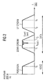
- Figure 2 shows in principle a frequency spectrum of signals transmitted via a conventional telephone line, wherein the voice signal is transmitted in a low frequency range and the data signal is transmitted in a high frequency range.
- the modem sends data from the broadband-communication device via the service splitter and socket A to the telephone network (so called upstream) and receives data from the telephone network via socket A and the service splitter (so called downstream) in a downstream frequency band.
- the upstream and downstream frequency bands are separated by a guard band, wherein the guard band is preferably within the amateur radio band to avoid disturbances caused by amateur radio.
- High-speed-xDSL-Modems receive data within the downstream-frequency band at a frequency which is very high and usually higher than 1 MHz.
- the wavelength ⁇ of the signals transmitted via the telephone line becomes smaller when the frequency f increases.
- the wavelength ⁇ will be in the magnitude of several meters, i.e. having a size in the magnitude of walls in a building. Therefore signal reflections will occur at additional sockets to which no devices are connected and which are electrically connected via a wire to a telephone line T such as socket B in figure 1.
- These additional outlets are seen by the high-speed modem as stubs of wire which are connected to the main transmission telephone line T. These stubs reflect the signal in a manner that cause disturbing "notches" in the signal frequency spectrum.
- Figure 2 shows "notches" which are caused by sockets to which no device is connected and which reflect signals.
- the frequency of the caused "notch” f notch and the severity of the notch are dependent on the length L of the extension wire shown in figure 1.
- D create when operated additional interference signals to the xDSL transmission in the xDSL data transmission frequency range. For example signals like clock signals from a cordless phone base station connected to socket D may disturb the xDSL data transmission.
- the termination device comprises a high-pass filter for separating signals within a frequency band used by a high speed modem, and impedance means connected to the high-pass filter, wherein said impedance means has an impedance that matches the impedance of the telephone line in the frequency band used by the high-speed modem, the termination device being further arranged to suppress high-frequency wave-like effects disturbing the data transmission over the telephone line.
- the termination device comprises a low-pass filter for separating telephone voice signals transmitted within a low frequency band.
- This provides the advantage that signal disturbances caused by a telephone set or a base station connected to the termination device are suppressed.
- the impedance of the impedance means is asymptotically resistive in the frequency domain.
- the impedance is as resistor.
- the impedance is preferably a resistor having 130 Ohms.
- the low-pass filter and the high-pass filter are passive filters.
- the cut-off frequency of the low-pass filter is about 700 kHz.
- the cut-off frequency of the high-pass filter is about 1 MHz.
- the low-pass filter and the high-pass filter of the termination device according to the present invention are active filters.
- the low frequency band is a POTS-frequency band reaching from 0 Hz to about 4 kHz.
- the low frequency band is an ISDN-frequency band reaching from 0 Hz to about 130 kHz.
- the high-speed modem is an xDSL-modem.
- This xDSL-modem is preferably a VDSL-Modem.
- the frequency band used by the high-speed modem comprises a data downstream frequency band and a data upstream-frequency band.
- the data downstream-frequency band reaches preferably from about 0.9 MHz to about 3.5 MHz and the data upstream-frequency band reaches from about 4 MHz to about 7.9 MHz.
- the low-pass filter has according to a preferred embodiment an output terminal for connecting a telephone set to the termination device.
- the low-pass filter and the high-pass filter are connected in parallel to each other.
- the telephone line is in a preferred embodiment an unshielded twisted-pair cable (UTP) made of copper.
- UTP unshielded twisted-pair cable
- the termination device is switched automatically to an input terminal connected to the telephone line when no telephone set is connected to the termination device.
- the termination device includes detection means which detects whether a telephone set is connected to the termination device and controls a switching unit to connect the high-pass filter with the telephone line in case that no telephone set in connected.
- the impedance of the impedance means is adjustable.
- the termination device is integrated in a telephone socket.
- the termination device is integrated in a telephone set.
- the termination device is integrated in a telephone jack.
- the termination device is integrated in a telephone extension wire.
- Telephone socket 2 is connected via a line 6 to a service splitter 7 for separating telephone voice signals from data signals.
- the separated telephone voice signals are transmitted bi-directionally via a signal line 8 to a telephone terminal 9 to which the telephone set 10 is connected via a signal line 11.
- the data signal separated by the splitter 7 is transmitted via data signal line 12 to a high-speed modem 13 such as an xDSL-modem.
- the xDSL-modem includes an remote transmission unit 14 which is connected via line 15 to a terminal unit 16.
- a broadband-communication device such as a laptop or a personal computer 17 is connected via a line 18 to the termination unit 16 of the high-speed modem 13.
- the socket 2 is connected via telephone wire 19 to a basement-transmitting unit 20 of a telephone network 21.
- the telephone wire 19 is usually an unshielded twisted-pair cable made of copper.
- sockets 3, 4, 5 which are connected to the telephone wire 19 via connecting wires 22, 23, 24, 25.
- Figure 3 just shows an example for a possible wiring structure within a room wall 1, however the number of sockets and the exact wiring may vary and is unknown.
- a termination device 30 according to the present invention is connected via connecting lines 26, 27, 28.
- a conventional telephone set 29 is connected via line 31.
- a cordless phone base station 32 is connected via line 33.
- the wiring structure can have any form such as a tree structure.
- a termination device 30 according to the present invention is provided for every telephone socket 3, 4, 5, 6 with the exception of telephone socket 2 connected to the high-speed modem 13 through service splitter 7.
- the termination device 30 according to the present invention may be integrated in the telephone sockets 3, 4, 5. In alternative embodiments the termination device 30 according to the present invention is integrated either in the telephone set, in a telephone jack or in a telephone extension wire.
- the termination device 30a shown in figure 3 prevents disturbing reflections from socket 3 via lines 22, 25 to the telephone wire 19 which might disturb the downstream data transmitted to the high-speed modem 13 in a high frequency band.
- the termination device 30 b as shown in figure 3 prevents signals which are created when the telephone set 29 is operated to cause interference with the xDSL data transmission in the xDSL high frequency range used by the high-speed modem 13.
- the termination device 30 c can prevent for example clock signals created by the cordless phone base station 32 from disturbing the xDSL data transmission signal within the xDSL high frequency data transmission range.
- the small termination devices 30 connected to sockets 3 to 5 suppress high frequency wavelike-effects like signal reflections and antenna effects which are disturbing factors effecting signal transmission over the telephone wire 19. Disturbing "notches” as shown in figure 2 are prevented by the small termination device 30 according to the present invention thus reducing data errors which might be caused by such "notches".
- the termination devices 30a to 30c according to the present invention as shown in figure 3 can be adapters to be plugged in the sockets 3 to 5 or can be in an alternative embodiment be integrated in the sockets 3 to 5.
- the high-speed modem 13 shown in figure 3 can be any modem using a high frequency band in the telephone wire 19 for data transmission, i.e. any xDSL-modem.
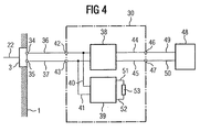
- FIG. 4 shows a block diagram of a preferred embodiment of the termination device 30 according to the present invention.
- the termination device 30 is for example connected to socket 3 shown in figure 4.
- Socket 3 comprises a pair of telephone wires 34, 35 to which the termination device 30 is connected via lines 36, 37.
- the connecting lines 36, 37 link a low-pass filter 38 to the telephone socket 3.
- a high-pass filter 39 is connected in parallel to the low-pass filter 38 by means of signal lines 40, 41.
- the termination device 30 comprise an input terminal 42, 43 to link the termination device 30 to the telephone socket 3 via lines 36, 37.
- the low-pass filter 38 is further connected via lines 44, 45 to terminals 46, 47 of the termination device 30.
- a telephone set 48 can be connected the terminals 46, 47 of the termination device 30 via lines 49, 50.
- the telephone set 48 might be plugged into the termination device but the termination device 30 according to the present invention works also when no telephone set 48 is connected to the low-pass filter 38.
- the high-pass filter 39 is connected via lines 51, 52 to impedance means 53.
- Impedance means 53 connected to the high-pas filter 39 comprises an impedance that matches the impedance of the telephone line used by the telephone network system and the frequency band used by the high-speed modem 13.
- the impedance of the impedance means 53 is not a complex impedance but a real impedance.
- the values of the impedance means 53 depend on the impedance of the telephone line of the used telephone system. In Germany the impedance of impedance means 53 is 130 Ohms.
- the low-pass filter 38 and the high-pass filter 39 can either be passive or active filters. Passive filters are preferred because the production costs are lower and no power supply for the filters is necessary.
- the cut-off frequency of the filters are in a preferred embodiment adjustable.
- the cut-off frequency of the low-pass filter 38 within a preferred embodiment is about 700 kHz and the cut-off frequency of the high-pass filter 39 is about 1 MHz.
- the low-pass filter 38 is provided for separating telephone voice signals transmitted bi-directionally to the telephone set 48 within a low frequency band.
- the low frequency band can be a POTS-frequency band which reaches from 0 Hz to about 4 kHz or in an alternative embodiment can be a ISDN-frequency band reaching from 0 Hz to 130 kHz.
- the high-pass filter 39 is provided for separating signals occurring on line 22 within a frequency band used by the high-speed modem 13 for data transmission.
- This high-speed modem 13 can be any xDSL- modem and in particular a VDSL-modem.
- the high frequency band used by the high-speed modem 13 as shown in figure 3 comprises a data downstream frequency band and a data upstream frequency band as shown in figure 2.
- the data downstream frequency band between frequency f 1 and frequency f 2 ranges in preferred embodiment from about 0.9 MHz to about 3.5 MHz and the data upstream frequency band between frequencies f 3 , f 4 reaches in a preferred embodiment from about 4 MHz to about 7.9 MHz.
- the cut-off frequencies of the low-pass filter 38 and the high-pass filter 39 are dimensioned depending on the high frequency band ranges used by the high-speed modem 13 for data transmission.
- the high-pass filter 39 is switched automatically by means of a switching unit to the telephone socket 3 when no telephone set such as telephone set 48 is connected to the termination device 30.
- the termination device 30 includes in a preferred embodiment detection means which detects whether the telephone set 48 is connected to the termination device 30, wherein the detection means controls the switching unit to connect the high-pass filter 39 with the telephone socket 3 is case that no telephone set 48 is connected to the termination device 30.
- the impedance of the impedance means 53 is adjustable. This impedance and the cut-off frequencies of the termination device 30 can be adjusted to the requirements of the telephone network within a country such as Germany and the United States.
- FIG. 5 shows a preferred embodiment of a termination device 30 according to the present invention having a passive low-pass filter 38 and a passive high-pass filter 39.
- the low-pass filter 38 and the high-pass filter 39 includes only passive components.
- the passive components comprise capacitors and inductivities. Both filters 38, 39 do not need any power supply and can be produced at low costs.
- Low-pass filter 38 comprises inductivities 54, 55, 56, 57 connected in series between lines 42 and 46. Further, low-pass filter 38 comprises inductivities 58, 59, 60, 61 connected in series between terminal 43 and terminal 47. Further the low-pass filter 38 includes inductivities 62, 63, 64 connected in series to capacitors 65, 66, 67.
- the high-pass filter 39 comprises two capacitors 62, 63 connected in series between terminal 42 and line 51. Further high-pass filter 39 includes two 64, 65 also connected in series between terminal 43 and line 52. Furthermore high-pass filter 39 as shown in figure 5 has a capacitor 66 connected to an inductivity 67. In a preferred embodiment as shown in figure 5 both filters have inductivities and filters with fixed values. In an alternative embodiment the components within the filters 38, 39 are adjustable to vary the cut-off frequency of the filters. As becomes evident from figure 5 the termination device 30 according to the present invention includes only passive components and can be therefore produced in a highly integrated manner making the termination device 30 according to the present invention a component which has a very small size. Further the production costs for the termination device 30 as shown in figure 5 are very low.
- the termination device 30 overcomes disturbing effects in a location with multiple telephone outlets connected to the same telephone line 19 where a high-speed modem 13 especially a VDSL-modem is also connected to that telephone line via an outlet 2.
- the termination device 30 maintains the functionality and increases the available quality and available maximum transmission distance of the high-speed data transmission service.
- the available quality is increased by lowering the bit error rate caused by signal notches in the downstream data transmission frequency band or in the upstream data transmission frequency band.
- the termination device 30 according to the present invention can be produced at low costs and small size. This has the additional advantage that the termination device 30 according to the present invention can be integrated into telephone sockets, the telephone jack a within the telephone set itself.
Claims (26)
- Abschlussvorrichtung (30) zur Verhinderung von Signalstörungen in der Datenübertragung eines Hochgeschwindigkeits-Modems (13), welches über einen Splitter (7) mit einer ersten Telefonsteckdose (2), die über eine Telefonleitung (19) an einer Basisübertragungseinheit (20) eines Telefonnetzwerks (21) angeschlossen ist, verbunden ist,
wobei die Abschlussvorrichtung (30) für eine zweite Telefonsteckdose (3, 4, 5), die mit der Telefonleitung (19) verbunden ist, vorgesehen ist,
wobei
die Abschlussvorrichtung aufweist:ein Hochpassfilter (39) zur Trennung von Signalen innerhalb eines von dem Hochgeschwindigkeits-Modem (13) zur Datenübertragung verwendeten Frequenzbands; undeine Impedanzeinrichtung (53), die mit dem Hochpassfilter (39) verbunden ist; wobei die Impedanzeinrichtung (53) eine Impedanz aufweist, welche der Impedanz der Telefonleitung (19) in dem von dem Hochgeschwindigkeits-Modem (13) verwendeten Frequenzband entspricht;wobei die Abschlussvorrichtung (30) weiterhin hochfrequenzwellenähnliche Effekte, welche die Datenübertragung über die Telefonleitung (19) stören, unterdrückt. - Abschlussvorrichtung nach Anspruch 1,
welche weiterhin ein Tiefpassfilter (38) zur Trennung eines innerhalb eines Niederfrequenzbands übertragenen Telefonsprachsignals aufweist. - Abschlussvorrichtung nach Anspruch 1 oder 2,
wobei
die Impedanz der Impedanzeinrichtung (53) asymptotisch resistiv ist. - Abschlussvorrichtung nach Anspruch 3,
wobei
die Impedanzeinrichtung (53) ein Widerstand ist. - Abschlussvorrichtung nach Anspruch 4,
wobei
die Impedanz des Widerstands (53) 130 Ohm beträgt. - Abschlussvorrichtung nach Anspruch 1,
wobei
das Tiefpassfilter (38) und das Hochpassfilter (39) passive Filter sind. - Abschlussvorrichtung nach einem der vorhergehenden Ansprüche,
wobei
die Grenzfrequenz des Tiefpassfilters (38) ungefähr 700 kHz beträgt. - Abschlussvorrichtung nach einem der vorhergehenden Ansprüche,
wobei
die Grenzfrequenz des Hochpassfilters (39) ungefähr 1 MHz beträgt. - Abschlussvorrichtung nach Anspruch 1,
wobei
das Tiefpassfilter (38) und das Hochpassfilter (39) aktive Filter sind. - Abschlussvorrichtung nach einem der vorhergehenden Ansprüche,
wobei
das Niederfrequenzband ein POTS-Frequenzband, welches sich von 0 Hz bis ungefähr 4 kHz erstreckt. - Abschlussvorrichtung nach einem der vorhergehenden Ansprüche 1 bis 9,
wobei
das Niederfrequenzband ein ISDN-Frequenzband im Bereich von 0 Hz bis ungefähr 130 kHz ist. - Abschlussvorrichtung nach einem der vorhergehenden Ansprüche,
wobei
das Hochgeschwindigkeits-Modem (13) ein xDSL-Modem ist. - Abschlussvorrichtung nach Anspruch 12,
wobei
das xDSL-Modem ein VDSL-Modem ist. - Abschlussvorrichtung nach einem der vorhergehenden Ansprüche,
wobei
das von dem Hochgeschwindigkeits-Modem (13) verwendete Frequenzband ein Daten-Downstream-Frequenzband und ein Daten-Upstream-Frequenzband aufweist. - Abschlussvorrichtung nach Anspruch 14,
wobei
das Daten-Downstream-Frequenzband sich von ungefähr 0,9 MHz bis ungefähr 3,5 MHz erstreckt, und sich das Daten-Upstream-Frequenzband von ungefähr 4 MHz bis ungefähr 7,9 MHz erstreckt. - Abschlussvorrichtung nach einem der vorhergehenden Ansprüche,
wobei
das Tiefpassfilter (38) einen Ausgangsanschluss (46, 47) zum Anschluss eines Telefonapparats (48) an die Abschlussvorrichtung (30) aufweist. - Abschlussvorrichtung nach einem der vorhergehenden Ansprüche,
wobei
das Tiefpassfilter (38) und das Hochpassfilter (39) parallel miteinander verbunden und an einem Eingangsanschluss (42, 43) der Abschlussvorrichtung (30) angeschlossen sind. - Abschlussvorrichtung nach einem der vorhergehenden Ansprüche,
wobei
die Telefonleitung ein ungeschirmtes Kabel mit verdrilltem Aderpaar (UTP) aus Kupfer ist. - Abschlussvorrichtung nach einem der vorhergehenden Ansprüche,
wobei
das Hochpassfilter (39) automatisch an den Eingangsanschluss (42, 43) geschaltet ist, wenn kein Telefonapparat (48) an der Abschlussvorrichtung (30) angeschlossen ist. - Abschlussvorrichtung nach einem der vorhergehenden Ansprüche,
wobei
die Abschlussvorrichtung (30) eine Abtasteinrichtung aufweist, welche abtastet, ob ein Telefonapparat an der Abschlussvorrichtung angeschlossen ist, und welche eine Schalteinheit in dem Fall, dass kein Telefonapparat (48) an der Abschlussvorrichtung (30) angeschlossen ist, zur Verbindung des Hochpassfilters (39) mit dem Eingangsanschluss (42, 43) steuert. - Abschlussvorrichtung nach einem der vorhergehenden Ansprüche,
wobei
die Impedanz der Impedanzeinrichtung (53) einstellbar ausgebildet ist. - Abschlussvorrichtung nach einem der vorhergehenden Ansprüche,
wobei
die Abschlussvorrichtung (30) in einer Telefonsteckdose integriert ist. - Abschlussvorrichtung nach einem der vorhergehenden Ansprüche 1 bis 21,
wobei
die Abschlussvorrichtung (30) in einem Telefonapparat integriert ist. - Abschlussvorrichtung nach einem der vorhergehenden Ansprüche 1 bis 21,
wobei
die Abschlussvorrichtung (30) in einer Telefonanschlusseinheit integriert ist. - Abschlussvorrichtung nach einem der vorhergehenden Ansprüche 1 bis 21,
wobei
die Abschlussvorrichtung (30) in einer Telefonanschlusseinheit integriert ist. - Abschlussvorrichtung nach einem der vorhergehenden Ansprüche,
wobei
die Grenzfrequenz des Tiefpassfilters (38) und des Hochpassfilters (39) einstellbar ausgebildet ist.
Applications Claiming Priority (1)
| Application Number | Priority Date | Filing Date | Title |
|---|---|---|---|
| PCT/EP2000/004649 WO2001091439A1 (en) | 2000-05-22 | 2000-05-22 | Termination device for a telephone line |
Publications (2)
| Publication Number | Publication Date |
|---|---|
| EP1284088A1 EP1284088A1 (de) | 2003-02-19 |
| EP1284088B1 true EP1284088B1 (de) | 2007-02-07 |
Family
ID=8163956
Family Applications (1)
| Application Number | Title | Priority Date | Filing Date |
|---|---|---|---|
| EP00938670A Expired - Lifetime EP1284088B1 (de) | 2000-05-22 | 2000-05-22 | Abschlussvorrichtung für eine fernsprechleitung |
Country Status (7)
| Country | Link |
|---|---|
| US (1) | US7548616B1 (de) |
| EP (1) | EP1284088B1 (de) |
| JP (1) | JP3926628B2 (de) |
| CN (1) | CN100369449C (de) |
| DE (1) | DE60033324T2 (de) |
| IL (1) | IL152540A0 (de) |
| WO (1) | WO2001091439A1 (de) |
Families Citing this family (3)
| Publication number | Priority date | Publication date | Assignee | Title |
|---|---|---|---|---|
| FR2839223B1 (fr) * | 2002-04-26 | 2004-07-30 | France Telecom | Dispositif de filtrage, pour modem haut debit en mode alternat, fonctionnant comme isolateur ou comme adaptateur |
| CN101605035B (zh) * | 2008-06-13 | 2012-05-23 | 鸿富锦精密工业(深圳)有限公司 | 调制解调器及其阻抗设定方法 |
| JP2020068428A (ja) * | 2018-10-23 | 2020-04-30 | キヤノン株式会社 | ファクシミリ装置、ファクシミリ装置の制御方法及びプログラム |
Family Cites Families (22)
| Publication number | Priority date | Publication date | Assignee | Title |
|---|---|---|---|---|
| US4018126A (en) * | 1975-03-26 | 1977-04-19 | Walmann Brian I | Tone generation and modification apparatus |
| US4442540A (en) * | 1981-06-04 | 1984-04-10 | Bell Telephone Laboratories, Incorporated | Data over voice transmission arrangement |
| EP0138485B1 (de) * | 1983-09-29 | 1990-04-04 | Nippon Telegraph And Telephone Corporation | Funkempfangssystem für ein phasenmoduliertes Signal |
| US5377230A (en) * | 1992-05-01 | 1994-12-27 | At&T Corp. | Extended bandwidth transmitter for crosstalk channels |
| EP0677938A1 (de) * | 1994-04-14 | 1995-10-18 | ALCATEL BELL Naamloze Vennootschap | Signalkoppler |
| US5757803A (en) * | 1995-11-27 | 1998-05-26 | Analog Devices, Inc. | Pots splitter assembly with improved transhybrid loss for digital subscriber loop transmission |
| US5987069A (en) | 1996-12-24 | 1999-11-16 | Gte Government Systems Corporation | Method and apparatus for variably allocating upstream and downstream communication spectra |
| JP3413060B2 (ja) * | 1997-05-13 | 2003-06-03 | 松下電器産業株式会社 | 直接変換受信機 |
| WO1998054901A1 (en) | 1997-05-30 | 1998-12-03 | Cais, Inc. | Twisted pair communication system |
| US5991311A (en) * | 1997-10-25 | 1999-11-23 | Centillium Technology | Time-multiplexed transmission on digital-subscriber lines synchronized to existing TCM-ISDN for reduced cross-talk |
| DE19747447A1 (de) * | 1997-10-28 | 1999-04-29 | Cit Alcatel | Vorrichtung zum Zusammenführen und Verstärken von zwei breitbandigen Signalen |
| GB9726037D0 (en) * | 1997-12-09 | 1998-02-04 | Northern Telecom Ltd | Communications signal splitter |
| US7027398B2 (en) * | 2001-04-12 | 2006-04-11 | General Instrument Corporation | Method and apparatus for monitoring voice conversations from customer premises equipment |
| US6359906B1 (en) * | 1998-02-24 | 2002-03-19 | Nortel Networks Limited | Providing digital services to telephone subscribers |
| SE511825C2 (sv) | 1998-03-31 | 1999-12-06 | Ericsson Telefon Ab L M | Förfarande och anordning i en analog linjekrets |
| US6873652B1 (en) * | 1998-04-01 | 2005-03-29 | Panasonic Communications Co., Ltd. | Activation of multiple xDSL modems with implicit channel probe |
| US6400772B1 (en) | 1998-06-16 | 2002-06-04 | Rc Networks | Line interface and method for detecting and eliminating an impedance mismatch between a transceiver and a transmission line |
| US6317493B1 (en) * | 1998-08-24 | 2001-11-13 | Bell Atlantic Network Services, Inc. | Automated system and method for subscriber line service control |
| US6731750B1 (en) * | 1998-10-30 | 2004-05-04 | Teraforce Technology Corporation | xDSL multiple-point interface device |
| US6567519B1 (en) * | 1999-05-28 | 2003-05-20 | Cisco Technology, Inc. | System and method for processing an input signal communicated on a telephone line |
| US6751315B1 (en) * | 1999-10-18 | 2004-06-15 | Silicon Labs Isolation, Inc. | High bandwidth phone line transceiver with capacitor isolation |
| US7106854B2 (en) * | 2000-01-25 | 2006-09-12 | Sbc Knowledge Ventures, L.P. | XDSL system having selectable hybrid circuitry |
-
2000
- 2000-05-22 US US10/258,581 patent/US7548616B1/en not_active Ceased
- 2000-05-22 WO PCT/EP2000/004649 patent/WO2001091439A1/en active IP Right Grant
- 2000-05-22 IL IL15254000A patent/IL152540A0/xx unknown
- 2000-05-22 JP JP2001586899A patent/JP3926628B2/ja not_active Expired - Fee Related
- 2000-05-22 DE DE60033324T patent/DE60033324T2/de not_active Expired - Lifetime
- 2000-05-22 CN CNB008195471A patent/CN100369449C/zh not_active Expired - Fee Related
- 2000-05-22 EP EP00938670A patent/EP1284088B1/de not_active Expired - Lifetime
Also Published As
| Publication number | Publication date |
|---|---|
| WO2001091439A1 (en) | 2001-11-29 |
| CN1452835A (zh) | 2003-10-29 |
| CN100369449C (zh) | 2008-02-13 |
| DE60033324T2 (de) | 2007-10-25 |
| DE60033324D1 (de) | 2007-03-22 |
| IL152540A0 (en) | 2003-05-29 |
| JP2003534727A (ja) | 2003-11-18 |
| JP3926628B2 (ja) | 2007-06-06 |
| US7548616B1 (en) | 2009-06-16 |
| EP1284088A1 (de) | 2003-02-19 |
Similar Documents
| Publication | Publication Date | Title |
|---|---|---|
| US8787562B2 (en) | Method and system for providing DC power on local telephone lines | |
| US6272219B1 (en) | Access network with an integrated splitter | |
| US6298037B1 (en) | Network data filtering | |
| WO1999034588A1 (en) | Apparatus and method for improved dsl communication | |
| US6239672B1 (en) | Wall mount filter for a digital subscriber line (xDSL) network and methods of installation and manufacture | |
| US6674843B1 (en) | Apparatus system and method for enabling multi-frequency communication over a telephone network having a billing/tax tone | |
| US7305006B1 (en) | System for allowing a single device to share multiple transmission lines | |
| US7039180B1 (en) | Method and apparatus for enabling multiple protocol communication over a network | |
| US6850618B1 (en) | Central office interface techniques for digital subscriber lines | |
| US6826278B2 (en) | Central office interface techniques for digital subscriber lines | |
| EP1284088B1 (de) | Abschlussvorrichtung für eine fernsprechleitung | |
| US20030147523A1 (en) | HPNA network bridge | |
| US6829336B1 (en) | System and method for active filtering in a telecommunications network | |
| US20120263295A1 (en) | Active microfilter for vdsl2 communication standard | |
| GB2386286A (en) | Combined VoDSL and POTS system with integrated access device/VoDSL to POTS converter and telephones connected to common line via isolating filters | |
| US6757380B2 (en) | Impedance blocking filter circuit for digital subscriber line communication systems | |
| KR100543927B1 (ko) | 전화선용 단말기 | |
| KR20010018110A (ko) | 랜 데이터 전송장치 | |
| KR100468836B1 (ko) | 디지털 가입자망의 채널 감쇄 특성 보상 및 신호간 상호 간섭 제거 방법 | |
| WO2006006932A1 (en) | Apparatus for high-speed data connection | |
| GB2339506A (en) | Line balancing interface to support simultaneous voice band and broadband data transmissions over in-house telephony wiring | |
| Dodds et al. | Simultaneous voice and Internet data on rural subscriber lines | |
| KR20030082016A (ko) | 고속 디지털 가입자 라인을 위한 선로 종단기 |
Legal Events
| Date | Code | Title | Description |
|---|---|---|---|
| PUAI | Public reference made under article 153(3) epc to a published international application that has entered the european phase |
Free format text: ORIGINAL CODE: 0009012 |
|
| 17P | Request for examination filed |
Effective date: 20021025 |
|
| AK | Designated contracting states |
Designated state(s): AT BE CH CY DE DK ES FI FR GB GR IE IT LI LU MC NL PT SE |
|
| RBV | Designated contracting states (corrected) |
Designated state(s): DE FR GB IT |
|
| 17Q | First examination report despatched |
Effective date: 20050429 |
|
| GRAP | Despatch of communication of intention to grant a patent |
Free format text: ORIGINAL CODE: EPIDOSNIGR1 |
|
| GRAS | Grant fee paid |
Free format text: ORIGINAL CODE: EPIDOSNIGR3 |
|
| GRAA | (expected) grant |
Free format text: ORIGINAL CODE: 0009210 |
|
| AK | Designated contracting states |
Kind code of ref document: B1 Designated state(s): DE FR GB IT |
|
| REG | Reference to a national code |
Ref country code: GB Ref legal event code: FG4D |
|
| REF | Corresponds to: |
Ref document number: 60033324 Country of ref document: DE Date of ref document: 20070322 Kind code of ref document: P |
|
| EN | Fr: translation not filed | ||
| PLBE | No opposition filed within time limit |
Free format text: ORIGINAL CODE: 0009261 |
|
| STAA | Information on the status of an ep patent application or granted ep patent |
Free format text: STATUS: NO OPPOSITION FILED WITHIN TIME LIMIT |
|
| 26N | No opposition filed |
Effective date: 20071108 |
|
| GBPC | Gb: european patent ceased through non-payment of renewal fee |
Effective date: 20070522 |
|
| PG25 | Lapsed in a contracting state [announced via postgrant information from national office to epo] |
Ref country code: FR Free format text: LAPSE BECAUSE OF FAILURE TO SUBMIT A TRANSLATION OF THE DESCRIPTION OR TO PAY THE FEE WITHIN THE PRESCRIBED TIME-LIMIT Effective date: 20070928 Ref country code: IT Free format text: LAPSE BECAUSE OF FAILURE TO SUBMIT A TRANSLATION OF THE DESCRIPTION OR TO PAY THE FEE WITHIN THE PRESCRIBED TIME-LIMIT Effective date: 20070207 |
|
| PG25 | Lapsed in a contracting state [announced via postgrant information from national office to epo] |
Ref country code: GB Free format text: LAPSE BECAUSE OF NON-PAYMENT OF DUE FEES Effective date: 20070522 |
|
| PG25 | Lapsed in a contracting state [announced via postgrant information from national office to epo] |
Ref country code: FR Free format text: LAPSE BECAUSE OF FAILURE TO SUBMIT A TRANSLATION OF THE DESCRIPTION OR TO PAY THE FEE WITHIN THE PRESCRIBED TIME-LIMIT Effective date: 20070207 |
|
| REG | Reference to a national code |
Ref country code: DE Ref legal event code: R081 Ref document number: 60033324 Country of ref document: DE Owner name: LANTIQ DEUTSCHLAND GMBH, DE Free format text: FORMER OWNER: INFINEON TECHNOLOGIES AG, 81669 MUENCHEN, DE Effective date: 20110325 Ref country code: DE Ref legal event code: R081 Ref document number: 60033324 Country of ref document: DE Owner name: LANTIQ BETEILIGUNGS-GMBH & CO. KG, DE Free format text: FORMER OWNER: INFINEON TECHNOLOGIES AG, 81669 MUENCHEN, DE Effective date: 20110325 |
|
| REG | Reference to a national code |
Ref country code: DE Ref legal event code: R081 Ref document number: 60033324 Country of ref document: DE Owner name: LANTIQ BETEILIGUNGS-GMBH & CO. KG, DE Free format text: FORMER OWNER: LANTIQ DEUTSCHLAND GMBH, 85579 NEUBIBERG, DE |
|
| PGFP | Annual fee paid to national office [announced via postgrant information from national office to epo] |
Ref country code: DE Payment date: 20180508 Year of fee payment: 19 |
|
| REG | Reference to a national code |
Ref country code: DE Ref legal event code: R119 Ref document number: 60033324 Country of ref document: DE |
|
| PG25 | Lapsed in a contracting state [announced via postgrant information from national office to epo] |
Ref country code: DE Free format text: LAPSE BECAUSE OF NON-PAYMENT OF DUE FEES Effective date: 20191203 |