BACKGROUND OF THE INVENTION
The present invention relates to a structure of a channel in a variable
displacement piston type compressor.
Japanese Unexamined Patent Publication No. 10-61548 discloses a
variable displacement piston type compressor. In the constitution, a drive shaft is
rotatably supported in a front housing and a cylinder block by a radial bearing.
Compression reactive force is generated due to the discharge work of a piston.
The compression reactive force is received by the front housing at its end wall
through the piston, a pair of shoes, a swash plate, a lug plate and a thrust bearing.
When the inclination angle of the swash plate is relatively small, the compression
reactive force is relatively small. However, the pressure in a crank chamber urges
the drive shaft in the direction from the rear side to the front side. Therefore, even
when the inclination angle of the swash plate is relatively small, the load acting to
the thrust bearing is relatively large.
To improve the durability of the thrust bearing, the thrust bearing requires
lubricating. In the prior art, the crank chamber and a suction chamber are
connected with each other by an axial passage formed in the drive shaft.
Refrigerant in the crank chamber flows into the suction chamber through the axial
passage. At this time, lubricant oil that flows with the refrigerant lubricates the
thrust bearing.
In the above constitution that an axial passage is formed in the drive shaft,
however, the diameter of the drive shaft is increased. Thereby, the size of the
compressor is increased. In addition, a cost for machining the drive shaft is
increased. Thereby, a cost for manufacturing the compressor is increased.
SUMMARY OF THE INVENTION
The present invention addresses a variable displacement piston type
compressor that improves the reliability of a portion requiring lubrication in a
crank chamber without increasing the size of the compressor.
According to the present invention, the present invention has following
features. A variable displacement piston type compressor has a housing, a drive
shaft, a cam plate and a piston. The housing has a cylinder block including a
plurality of cylinder bores. The housing defines a crank chamber, a suction
pressure region and a discharge pressure region. The suction pressure region
includes a suction chamber. The discharge pressure region includes a discharge
chamber. The drive shaft is rotatably supported by the housing. The drive shaft
has a first end and a second end. The first end of the drive shaft extends through
the housing. The cylinder block is placed between the first end and the second
end. The suction chamber and the discharge chamber are defined near the first
end relative to the cylinder block. The crank chamber is defined near the second
end relative to the cylinder block. The cam plate is inclinably supported by the
drive shaft in the crank chamber. The cam plate is integrally rotated with the drive
shaft. The piston is accommodated in each cylinder bore. The rotation of the cam
plate is converted into the reciprocating movement of the piston in accordance
with the inclination angle of the cam plate. Refrigerant in the suction chamber is
drawn into the cylinder bores due to the suction work of the piston. The refrigerant
in the cylinder bores is discharged into the discharge chamber due to the
discharge work of the piston. Refrigerant in the discharge pressure region is
supplied into the crank chamber and the refrigerant in the crank chamber is bled
into the suction pressure region through a bleed passage for controlling pressure
in the crank chamber. Thereby, the inclination angle of the cam plate is controlled.
The crank chamber and the suction chamber are connected with each other
through the bleed passage. The bleed passage is formed outside of the drive
shaft.
Furthermore, the present invention has following features. A variable
displacement piston type compressor has a cylinder block, a piston, a cam plate,
a crank chamber, a drive shaft, a suction chamber and a discharge chamber. The
cylinder block includes a plurality of cylinder bores. The piston functions so as to
compress refrigerant in each cylinder bore. The cam plate is movably connected
to the piston for reciprocating the piston. The crank chamber is defined near one
end of the cylinder block. The drive shaft has a rotational axis for rotating to drive
the cam plate. The drive shaft is urged in a direction of the rotational axis while
the piston reciprocates. The suction chamber is defined near the opposite end to
the crank chamber relative to the cylinder block. The refrigerant in the suction
chamber is drawn into the cylinder bores due to the suction work of the piston.
The discharge chamber is defined near the opposite end to the crank chamber
relative to the cylinder block. The refrigerant in each cylinder bore is discharged
to the discharge chamber due to the discharge work of the piston. The refrigerant
in the discharge chamber is supplied into the crank chamber and the refrigerant in
the crank chamber is bled into the suction chamber through a bleed passage for
controlling pressure in the crank chamber. The bleed passage is formed outside
of the drive shaft.
BRIEF DESCRIPTION OF THE DRAWINGS
The features of the present invention that are believed to be novel are set
forth with particularity in the appended claims. The invention together with objects
and advantages thereof, may best be understood by reference to the following
description of the presently preferred embodiments together with the
accompanying drawings in which:
DETAILED DESCRIPTION OF THE PREFERRED EMBODIMENTS
A first preferred embodiment according to the present invention in a
variable displacement piston type compressor will now be described with
reference to FIGs. 1A through 5. Referring particularly to FIG. 1A, the left side
and the right side of the drawing respectively correspond to the front side and the
rear side of the compressor.
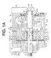
As shown in FIG. 1A, a front housing 11 and a rear housing 12 constitute
a compressor housing 10. An end surface of a circumferential wall 34 of the front
housing 11 and an end surface of a circumferential wall 35 of the rear housing 12
are secured to each other through a gasket 36. The front housing 11 and the rear
housing 12 are fixed to each other by a plurality of bolts 37.
Still referring to FIG. 1A, a valve port plate 20, a suction valve plate 21, a
discharge valve plate 22 and a retainer plate 23 are fitted in the front housing 11.
A suction chamber 111 and a discharge chamber 112 are defined between the
valve port plate 20 and an end wall 32 of the front housing 11. As shown in FIG. 4,
the suction chamber 111 is separated from the discharge chamber 112 by a
separation wall 33 and is surrounded by the discharge chamber 112. The
reference numerals in FIG. 4 are applied to substantially the same components in
FIG. 1A, and the corresponding description will be provided later with respect to
FIG. 1A if it has not yet been provided. If the description has been previously
given, it will not be reiterated.
Referring back to FIG. 1A, a cylinder block 19 is fitted in the front housing
11 so as to secure the suction valve plate 21. The end wall 32 of the front housing
11 is screwed by a plurality of screws 38 through the cylinder block 19. Thereby,
the cylinder block 19 is fixed to the front housing 11. The cylinder block 19 has a
plurality of cylinder bores 191. Although only one cylinder bore 191 is shown in
FIG. 1A, five cylinder bores are arranged around the drive shaft 13 in the present
embodiment as shown in FIGs. 2 and 3. The reference numerals in FIGs. 2 and 3
are applied to substantially the same components in FIG. 1A, and the
corresponding description will be provided later with respect to FIG. 1A if it has
not yet been provided. If the description has been previously given, it will not be
reiterated.
Referring back to FIG. 1A, the rear housing 12 and the cylinder block 19
define a crank chamber 121. A drive shaft 13 is rotatably supported by radial
bearings 40 and 41 respectively in the rear housing 12 and the cylinder block 19.
In a shaft hole 24 of the cylinder block 19 a pair of accommodation chambers 241
and 242 is defined at the front and rear sides of a flange 192 of the cylinder block
19. The radial bearing 41 is accommodated in the accommodation chamber 241.
The drive shaft 13 extends outside of the compressor housing 10 through the
shaft hole 24 of the cylinder block 19 and a shaft hole 113 of the front housing 11.
A front end of the drive shaft 13 connects with an external drive source such as a
vehicle engine through a power transmission mechanism (not shown). Thereby,
the drive shaft 13 is driven by the external drive source. A shaft seal 39 is placed
in the shaft hole 113 so as to prevent the refrigerant in the suction chamber 111
from leaking to the outside of the compressor housing 10 along the
circumferential surface 113 of the drive shaft 13.
Still referring to FIG. 1A, a lug plate 14 is secured to the drive shaft 13. A
swash plate 15 is supported by the drive shaft 13 so as to slide along a rotational
axis of the drive shaft 13 and is inclinable with respect to the axis of the drive
shaft 13. As shown in FIG. 5, a pair of guide pins 16 is secured to the swash plate
15. The reference numerals in FIG. 5 are applied to substantially the same
components in FIG. 1A, and the corresponding description will be provided later
with respect to FIG. 1A if it has not yet been provided. If the description has been
previously given, it will not be reiterated. The guide pins 16 are respectively
slidably fitted into a pair of guide holes 141 formed in the lug plate 14. The
cooperation of the guide holes 141 and the guide pins 16 allow the swash plate
15 to incline with respect to the axis of the drive shaft 13 and to rotate integrally
with the drive shaft 13. The inclination of the swash plate 15 is guided by the
slidable movement of the guide pins 16 in the corresponding guide holes 141
under the condition that the swash plate 15 is slidably supported by the drive
shaft 13.
Referring back to FIG. 1A, a piston 17 is accommodated in a
corresponding one of the cylinder bores 191. Each of the pistons 17 is connected
to the swash plate 15. The rotational movement of the swash plate 15, which
integrally rotates with the drive shaft 13, is converted into the reciprocating
movement of the piston 17 through a pair of shoes 18. Thereby, the piston 17
reciprocates in the corresponding cylinder bores 191 frontward and rearward.
The suction chamber 111 is included in a suction pressure region. While
the piston 17 moves from the left side to the right side in FIG. 1A, the refrigerant
in the suction chamber 111 pushes away a corresponding suction valve 211
formed on the suction valve plate 21 from a corresponding suction port 201
formed on the valve port plate 20. Thereby, the refrigerant in the suction chamber
111 is drawn into the corresponding cylinder bore 191. While the piston 17 moves
from the right side to the left side in FIG. 1A, the refrigerant that has been drawn
into the cylinder bore 191 pushes away a corresponding discharge valve 221
formed on the discharge valve plate 22 from a corresponding discharge port 202
formed on the valve port plate 20. Thereby, the refrigerant in the cylinder bore 191
is discharged into the corresponding discharge chamber 112. The discharge
chamber 191 is included in a discharge pressure region. The opening degree of
the discharge valve 221 is restricted by the abutment of the discharge valve 221
against the retainer 231, which is formed on the retainer plate 23.
In the present embodiment, the valve port plate 20, the suction valve
plate 21, the discharge valve plate 22 and the retainer plate 23 constitute a valve
plate assembly. A thrust bearing 42 is interposed between the end wall 122 of the
rear housing 12 and the lug plate 14. Compression reactive force is generated
due to the discharge work of the piston 17 and is received by the end wall 122 of
the rear housing 12 through the piston 17, the shoes 18, the swash plate 15, the
guide pins 16, the lug plate 14 and the thrust bearing 42. At this time, the drive
shaft 13 is urged in the direction of a central axis L of the drive shaft 13 while the
piston 17 reciprocates.
A supply passage 30 connects with the discharge chamber 112 and the
crank chamber 121. The refrigerant in the discharge chamber 112 is sent to the
crank chamber 121 through the supply passage 30. In the supply passage 30, an
electromagnetic type displacement control valve 25 is placed. The displacement
control valve 25 is magnetized and demagnetized by a controller (not shown).
The controller controls magnetization and demagnetization of the displacement
control valve 25 based on a temperature detected by a temperature detector (not
shown) that detects temperature in a vehicle compartment and a target
temperature set by a temperature setting device (not shown). The displacement
control valve 25 is closed while electricity is supplied to the displacement control
valve 25. The displacement control valve 25 is open while the electricity is
stopped being supplied to the displacement control valve 25. That is, on one hand
the refrigerant in the discharge chamber 112 is sent to the crank chamber 121
while the displacement control valve 25 is demagnetized, and on the other hand
the refrigerant in the discharge chamber 112 is not sent to the crank chamber 121
while the displacement control valve 25 is magnetized. Thus, the displacement
control valve 25 controls the amount of refrigerant that flows from the discharge
chamber 112 to the crank chamber 121.
In the accommodation chamber 242, a thrust bearing 43 and a shaft seal
44 are placed. The pressure in the crank chamber 121 is applied to the rear end
surface 132 of the drive shaft 13. In the case that the sum of the compression
reactive forces acting on the pistons 17 in the cylinder bores 191 is smaller than
the force resulting from the pressure applied to the rear end surface 132, the
force differential between the sum of the compression reactive forces and the
force resulting from the pressure applied to the rear end surface 132 is received
by the cylinder block 19 through the drive shaft 13 and the thrust bearing 43. The
shaft seal 44 prevents the refrigerant in the suction chamber 111 from leaking to
the crank chamber 111 along the circumferential surface 133 of the drive shaft 13.
In the cylinder block 19, a refrigerant passage 45 is formed. The
refrigerant passage 45 has a first end 451 and a second end 452. The first end
451 is opened to a bottom of the crank chamber 121. As shown in FIGs. 2 and 3,
the second end 452 is opened to a clearance S1 defined between the inner
circumference of the flange 192 and the circumferential surface 133 of the drive
shaft 13. The second end 452 is formed more upward than the central axis L of
the drive shaft 13. A throttled passage 31 is formed in the refrigerant passage 45.
As shown in FIGs. 1A and 1B, the crank chamber 121 connects with the
suction chamber 111 through the refrigerant passage 45, the clearance S1, the
gap inside of the radial bearing 41, the accommodation chamber 241, and a shaft
hole 203 formed in the valve port plate 20. The refrigerant passage 45, the
clearance S1, the radial bearing 41, the accommodation chamber 241, and the
shaft hole 203 constitute a bleed passage 46. The refrigerant in the crank
chamber 121 flows into the suction chamber 111 through the bleed passage 46
that connects the crank chamber 121 to the suction chamber 111. The
circumferential surface 133 of the drive shaft 13 and the bleed passage 46 in the
cylinder block 19 (or the refrigerant passage 45 in the cylinder block 16) meet
with each other more upward than the central axis L of the drive shaft 13.
The inclination angle of the swash plate 15 is varied base on the control
of the pressure in the crank chamber 121. As the pressure in the crank chamber
121 increases, the inclination angle of the swash plate 15 is decreased relative to
the perpendicular plane to the drive shaft 13. In contrast, as the pressure in the
crank chamber 121 decreases, the inclination angle of the swash plate 15 is
increased relative to the perpendicular plane to the drive shaft 13. As the
refrigerant in the discharge chamber 112 is supplied to the crank chamber 121,
the pressure in the crank chamber 121 is increased. When the supply of the
refrigerant from the discharge chamber 112 to the crank chamber 121 stops, the
pressure in the crank chamber 121 is decreased. That is, the inclination angle of
the swash plate 15 is controlled by the displacement control valve 25.
The maximum inclination angle of the swash plate 15 is restricted by the
abutment of the swash plate 15 against the lug plate 14. The minimum inclination
angle of the swash plate 15 is restricted by the abutment of the swash plate 15
against the circular clip 47.
The discharge chamber 112 and the suction chamber 111 connect with
each other through an external refrigerant circuit 26. The refrigerant that has
been flowed into the external refrigerant circuit 26 from the discharge chamber
112 is returned to the suction chamber 111 in the compressor through a
condenser 27, an expansion valve 28 and an evaporator 29.
In the first preferred embodiment of the present invention, the following
advantageous effects are obtained.
A second preferred embodiment according to the present invention in a
variable displacement piston type compressor will now be described with
reference to FIG. 6. The same reference numerals of the first preferred
embodiment are applied to substantially the same elements in the second
preferred embodiment.
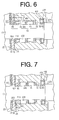
Referring to FIG. 6, a shaft seal 44A is placed in the accommodation
chamber 241. The shaft seal 44A prevents the refrigerant in the accommodation
chamber 241 from leaking to the suction chamber 111 along the circumferential
surface 133 of the drive shaft 13. The accommodation chamber 241 and the
suction chamber 111 are connected by a refrigerant passage 48 formed in the
cylinder block 19 and a throttled passage 49 formed through the valve port plate
20. A first end 481 of the refrigerant passage 48 is opened relatively upward in
the accommodation chamber 241.
A clearance S2 is defined between an inner circumferential surface of a
race 431 of the thrust bearing 43 and the circumferential surface 133 of the drive
shaft 13. The refrigerant in the crank chamber 121 flows to the suction chamber
111 through a bleed passage 50 constituted of a gap between the race 431 and a
race 432 of the thrust bearing 43, the clearance S2, the clearance S1, a gap in
the radial bearing 41, the accommodation chamber 241, the refrigerant passage
48 and the throttled passage 49.
In the second preferred embodiment, the above-described effects (1-1)
through (1-4) of the first preferred embodiment are substantially obtained. In
addition, the following effects are obtained.
A third preferred embodiment according to the present invention in a
variable displacement piston type compressor will now be described with
reference to FIG. 7. The same reference numerals of the first preferred
embodiment are applied to substantially the same elements in the third preferred
embodiment.
An annular blocking body 51 made of synthetic resin is placed in the
accommodation chamber 241. For example, the blocking body 51 is made of
polytetrafluoroethylene. The blocking body 51 is slidable respective to the
circumferential surface in the accommodation chamber 241, the circumferential
surface 133 of the drive shaft 13 and the suction valve plate 21. Grooves 52 and
521 are formed respectively on the outer circumferential surface 512 and the end
surface 513 of the blocking body 51. The refrigerant in the crank chamber 121
flows to the suction chamber 111 through the gap in the thrust bearing 43, the
clearances S2 and S1, the gap in the thrust bearing 41, the accommodation
chamber 241, the grooves 52 and 521, and the shaft hole 203. That is, the
pressure in the crank chamber 121 is adjusted by the outflow of the refrigerant in
the crank chamber 121 (or the release of the pressure in the crank chamber 121)
through the grooves 52 and 521 of the blocking body 51 that are throttling means.
The grooves 52 and 521 of the blocking body 51 function as a throttle so as to
separate the pressure in the suction chamber 111 from the pressure in the crank
chamber 121.
In the third preferred embodiment, the above-described effects (1-1)
through (1-4) of the first preferred embodiment are substantially obtained. In
addition, the following effects are obtained.
In the present invention, the following embodiments are also practiced.
Firstly, a bleed passage that linearly extends through the cylinder block
19, the suction valve plate 21, the valve port plate 20 and the discharge valve
plate 22 may connect with the crank chamber 121 and the suction chamber 111.
Secondly, in the second preferred embodiment, the refrigerant passage
48 and the throttled passage 49 may be omitted. In place of the refrigerant
passage 48 and the throttled passage 49, a throttled passage may be formed in
the shaft seal 44A.
Thirdly, in the third preferred embodiment, a blocking body 51 made of
rubber may be employed. For example, a nitrile-butadiene rubber may be
employed.
The nitrile-butadiene rubber that is excellent in a resistance to
deterioration relative to refrigerant and lubricant oil is suitable for a material of the
blocking body 51. While the blocking body 51 made of rubber is formed by
molding, the elastic deformation of rubber allows rubber to be lower accuracy in
size than synthetic resin. Therefore, the blocking body 51 made of rubber is
manufactured more easily than a blocking body made of synthetic resin.
The present examples and embodiments are to be considered as
illustrative and not restrictive and the invention is not to be limited to the details
given herein but may be modified within the scope of the appended claims.