EP1283345A2 - Cylinder head cooling structure for an internal combustion engine - Google Patents
Cylinder head cooling structure for an internal combustion engine Download PDFInfo
- Publication number
- EP1283345A2 EP1283345A2 EP02016561A EP02016561A EP1283345A2 EP 1283345 A2 EP1283345 A2 EP 1283345A2 EP 02016561 A EP02016561 A EP 02016561A EP 02016561 A EP02016561 A EP 02016561A EP 1283345 A2 EP1283345 A2 EP 1283345A2
- Authority
- EP
- European Patent Office
- Prior art keywords
- path
- cooling
- cylinder head
- flow rate
- central
- Prior art date
- Legal status (The legal status is an assumption and is not a legal conclusion. Google has not performed a legal analysis and makes no representation as to the accuracy of the status listed.)
- Withdrawn
Links
Images

Classifications
-
- F—MECHANICAL ENGINEERING; LIGHTING; HEATING; WEAPONS; BLASTING
- F02—COMBUSTION ENGINES; HOT-GAS OR COMBUSTION-PRODUCT ENGINE PLANTS
- F02F—CYLINDERS, PISTONS OR CASINGS, FOR COMBUSTION ENGINES; ARRANGEMENTS OF SEALINGS IN COMBUSTION ENGINES
- F02F1/00—Cylinders; Cylinder heads
- F02F1/24—Cylinder heads
- F02F1/42—Shape or arrangement of intake or exhaust channels in cylinder heads
- F02F1/4214—Shape or arrangement of intake or exhaust channels in cylinder heads specially adapted for four or more valves per cylinder
-
- F—MECHANICAL ENGINEERING; LIGHTING; HEATING; WEAPONS; BLASTING
- F02—COMBUSTION ENGINES; HOT-GAS OR COMBUSTION-PRODUCT ENGINE PLANTS
- F02B—INTERNAL-COMBUSTION PISTON ENGINES; COMBUSTION ENGINES IN GENERAL
- F02B75/00—Other engines
- F02B75/16—Engines characterised by number of cylinders, e.g. single-cylinder engines
- F02B75/18—Multi-cylinder engines
- F02B75/20—Multi-cylinder engines with cylinders all in one line
-
- F—MECHANICAL ENGINEERING; LIGHTING; HEATING; WEAPONS; BLASTING
- F02—COMBUSTION ENGINES; HOT-GAS OR COMBUSTION-PRODUCT ENGINE PLANTS
- F02F—CYLINDERS, PISTONS OR CASINGS, FOR COMBUSTION ENGINES; ARRANGEMENTS OF SEALINGS IN COMBUSTION ENGINES
- F02F1/00—Cylinders; Cylinder heads
- F02F1/24—Cylinder heads
- F02F1/26—Cylinder heads having cooling means
- F02F1/36—Cylinder heads having cooling means for liquid cooling
- F02F1/40—Cylinder heads having cooling means for liquid cooling cylinder heads with means for directing, guiding, or distributing liquid stream
-
- F—MECHANICAL ENGINEERING; LIGHTING; HEATING; WEAPONS; BLASTING
- F02—COMBUSTION ENGINES; HOT-GAS OR COMBUSTION-PRODUCT ENGINE PLANTS
- F02B—INTERNAL-COMBUSTION PISTON ENGINES; COMBUSTION ENGINES IN GENERAL
- F02B75/00—Other engines
- F02B75/16—Engines characterised by number of cylinders, e.g. single-cylinder engines
- F02B75/18—Multi-cylinder engines
- F02B2075/1804—Number of cylinders
- F02B2075/1816—Number of cylinders four
-
- F—MECHANICAL ENGINEERING; LIGHTING; HEATING; WEAPONS; BLASTING
- F05—INDEXING SCHEMES RELATING TO ENGINES OR PUMPS IN VARIOUS SUBCLASSES OF CLASSES F01-F04
- F05C—INDEXING SCHEME RELATING TO MATERIALS, MATERIAL PROPERTIES OR MATERIAL CHARACTERISTICS FOR MACHINES, ENGINES OR PUMPS OTHER THAN NON-POSITIVE-DISPLACEMENT MACHINES OR ENGINES
- F05C2201/00—Metals
- F05C2201/02—Light metals
- F05C2201/021—Aluminium
Definitions
- the present invention relates to a cylinder head cooling structure which causes cooling water to flow through a cooling water path formed in the cylinder head of an internal combustion engine, from an inflow portion to an outflow portion, thereby cooling the cylinder head heated by a combustion chamber.
- the cylinder head of an internal combustion engine is provided with a cooling water path for cooling against heating by the combustion chamber.
- this cooling water path is formed such that cooling water can flow around wall portions forming an intake port and an exhaust port.
- JP 5-86969 A discloses a structure in which, in order to pass as much cooling water as possible through the portion between the intake port and the exhaust port and to cool the inter-port portion subject to high temperature, the cooling water path is divided by a partition wall for each combustion chamber, and a protruding wall for guiding the flowing direction of cooling water toward the inter-port portion is formed at some midpoint of the partition wall.
- a cylinder head cooling structure for an internal combustion engine which is capable of efficiently cooling the central portion of the cylinder head and which appropriately distributes the cooling water flow rate throughout the cylinder head, whereby it is possible to achieve an improvement in cooling efficiency.
- a cylinder head cooling structure for an internal combustion engine in which a cooling liquid is caused to flow from an inflow portion to an outflow portion through a cooling liquid path formed in the cylinder head of the internal combustion engine equipped with a port row in which at least one intake valve and at least one exhaust valve are arranged, so that the cylinder head heated by a combustion chamber is cooled, characterized in that: the cooling liquid path comprising an intake side cooling path formed between an intake port wall portion forming an intake port row and a cylinder head peripheral wall portion, an exhaust side cooling path formed between an exhaust port wall portion forming an exhaust port row and a cylinder head peripheral wall portion, and a central cooling path formed between the intake port wall portion and the exhaust port wall portion; and a communication means communicating the central cooling path with at least one of the intake side cooling path and the exhaust side cooling path is formed, that a high flow rate portion and a low flow rate portion are formed in the central cooling path through the intermediation of the communication means, and that
- the internal combustion engine equipped with a port row in which at least one intake valve and at least one exhaust valve are arranged includes a single-cylinder engine and a multi-cylinder internal combustion engine, and also includes a two-valve system in which each cylinder has one intake valve and one exhaust valve and a four-valve system in which each cylinder has two intake valves and two exhaust valves, etc.
- the communication means may be one having only one communication path or one having a plurality of communication paths.
- the high flow rate portion and the low flow rate portion are determined in correspondence with upstream side and downstream side portions of the communication path when there is only one communication path, and determined in correspondence with each of the portion between adjacent communication paths, the portion between the uppermost-stream side communication path and the upstream end, and the portion between the downmost-stream side communication path and the downstream end when there are a plurality of communication paths.
- the portion between the upstream end of the central cooling path and the adjacent communication path when cooling liquid flows into the central cooling path from the communication path adjacent to the upstream end, the portion between the upstream end and the communication path is the low flow rate portion, and when no cooling liquid flows into the central cooling path from the communication path, the portion between the upstream end and the communication path is the high flow rate portion.
- central portion used in Claim 1 will be defined as follows:
- the central cooling path of the portion adjacent to the cylinders other than those at the ends will be referred to as the central portion.
- the central cooling path of the portion adjacent to the central two cylinders other than those at the ends is the central portion.
- Embodiment 2 shown in Fig. 3 which consists of a four-valve type engine with two in-line cylinders in which a communication path is formed between the two intake port wall portions formed on the respective cylinders, the two end intake ports of the four intake ports are excluded, and the central cooling path of the portion adjacent to the remaining two central intake ports is the central portion.
- the proportion of the longitudinal length of the cylinder head of the high flow rate portion formed in a central portion of the central cooling path with respect to the longitudinal length of the cylinder head of the central portion (37) of the central cooling path is larger than the proportion of the longitudinal length of the cylinder head of the high flow rate portion formed in the end portions other than the central portion of the central cooling path with respect to the length of the end portions other than the central portion of the central cooling path.
- the proportion of the longitudinal length of the cylinder head of the high flow rate portion formed in the central portion of the central cooling path with respect to the longitudinal length of the cylinder head of the central portion of the central cooling path is larger than the proportion of the longitudinal length of the cylinder head of the high flow rate portion formed in the end portions other than the central portion of the central cooling path with respect to the length of the end portions other than the central portion of the central cooling path, only a portion of the central portion of the central cooling path may be the high flow rate portion, or a portion of the end portions other than the central portion of the central cooling path may be the high flow rate portion.
- the present invention may provide the cylinder head cooling structure for an internal combustion engine is characterized in that the high flow rate portion accounts for the central portion, and the low flow rate portion accounts for the end portions.
- the central portion which is subject to generation of thermal stress, can be efficiently cooled and, further, the cooling liquid flow rate is appropriately distributed throughout the cylinder head, whereby it is possible to provide a cylinder head cooling structure for an internal combustion engine with enhanced cooling efficiency.
- the present invention may provide a cylinder head cooling structure for an internal combustion engine in which a cooling liquid is caused to flow from an inflow portion to an outflow portion through a cooling liquid path formed in the cylinder head of the internal combustion engine equipped with a port row in which at least one intake valve and at least one exhaust valve are arranged, so that the cylinder head heated by a combustion chamber is cooled, characterized in that: the cooling liquid path comprising an intake side cooling path formed between an intake port wall portion forming an intake port row and a cylinder head peripheral wall portion, an exhaust side cooling path formed between an exhaust port wall portion forming an exhaust port row and a cylinder head peripheral wall portion, and a central cooling path formed between the intake port wall portion and the exhaust port wall portion; and a communication means communicating the central cooling path with at least one of the intake side cooling path and the exhaust side cooling path is formed, a high flow rate portion and two low flow rate portions are formed in the central cooling path through the intermediation of the communication means, and the high flow rate portion and two low flow rate portions
- the present invention may provide the cylinder head cooling structure for an internal combustion engine is characterized in that regarding at least one of the plurality of communication paths constituting the communication means, a flow rate control portion is provided in the intake side cooling path or the exhaust side cooling path communicating with the central cooling path through the communication path at a position on the downstream side of the communication path, so that cooling liquid is caused to flow into the central cooling path through the communication path, forming the high flow rate portion on the downstream side of the communication path of the central cooling path.
- a flow rate control portion is provided at some midpoint of the intake side cooling path or the exhaust side cooling path communicating with the central cooling path.
- the flow rate control portion there is no particular restriction in configuration and it may be formed, for example, by causing a part of the port wall portion or the cylinder head peripheral wall portion to protrude, or providing at some midpoint of the cooling path a portion separate from the wall portion which narrows the flow path; various designs are possible which narrow or cut off the cooling path.
- the present invention may provide the cylinder head cooling structure for an internal combustion engine is characterized in that a flow rate control portion is provided in at least one of the intake side cooling path and the exhaust side cooling path, so that a high flow rate portion is formed in the central cooling path, and one of the plurality of communication paths constituting the communication means is provided on the downstream side of the flow rate control portion, so that cooling liquid in the central portion is caused to flow into the communication path, forming a low flow rate portion on the downstream side of the communication path of the central cooling path.
- cooling liquid is reliably caused to flow through the central portion, which is subject to generation of thermal stress, and it is possible to easily realize the bypassing of the end portions, which offer high flow resistance but do not always require a large amount of cooling liquid.
- the central portion of the cylinder head can be efficiently cooled, and further, the cooling liquid flow rate is appropriately distributed throughout the cylinder head, whereby it is possible to provide a cylinder head cooling structure for an internal combustion engine which can attain an enhancement in cooling efficiency.
- the present invention may provide the cylinder head cooling structure for an internal combustion engine is characterized in that the inflow portion has a plurality of holes, at least one of which is provided on the upstream side of the flow rate control portion, and is an intermediate inflow portion forming a flow path allowing cooling liquid to flow to the central cooling path through the communication path.
- the present invention may provide the cylinder head cooling structure for an internal combustion engine is characterized in that the cylinder head is applied to an internal combustion engine in which each combustion chamber has two intake ports and two exhaust ports and in which not less than three cylinders are arranged.
- Embodiments of the present invention will now be described with reference to the drawings. First, Embodiment 1 will be described.
- Fig. 1 is a horizontal sectional view of the cylinder head 1 of an internal combustion engine according to Embodiment 1 as seen from the opposite side to the cylinder block (not shown), that is, as seen from above.
- the cylinder head 1 is applied to a four-valve type internal combustion engine with four in-line cylinders.
- the cylinder head 1 is formed as an integral unit in the form of a casting of aluminum alloy.
- the cylinder head 1 has two intake ports for each cylinder: intake ports 11a and 11b, 12a and 12b, 13a and 13b, and 14a and 14b, and has two exhaust ports for each cylinder: exhaust ports 21a and 21b, 22a and 22b, 23a and 23b, and 24a and 24b.
- intake ports 11a and 11b, 12a and 12b, 13a and 13b, and 14a and 14b there are respectively arranged intake valves and exhaust valves (not shown). All the intake ports and exhaust ports are respectively arranged in a row, forming an intake port row 10 and an exhaust port row 20.
- the intake port row 10 and the exhaust port row 20 are adjacent to each other.
- all the intake ports of the intake port row 10 will also be collectively referred to as the intake ports 10
- all the exhaust ports of the exhaust port row 20 will also be collectively referred to as the exhaust ports 20.
- intake ports 10 they are formed by intake port wall portions 11c, 12c, 13c, and 14c, each of which integrally forms two ports for each cylinder, and regarding the exhaust ports 20, they are formed by an exhaust port wall portion 20c which integrally forms all the exhaust ports 21a through 24b.
- the intake ports 10 and exhaust ports 20 thus formed are open on the lower side in direction of combustion chambers (not shown). These ports are formed through punching by means of cores when forming the cylinder head 1 by casting or the like.
- the intake port wall portions 11c, 12c, 13c, and 14c respectively have fuel injection valve insertion holes 11d, 12d, 13d, and 14d.
- These fuel injection valve insertion holes 11d through 14d are formed by machining so as to open at the centers of the cylinders (not shown).
- a cooling water path 5 serving as a cooling liquid path for cooling the cylinder head 1 heated by the combustion chambers (not shown).
- the cooling water path 5 is formed through punching by means of a core when forming the cylinder head 1 by casting or the like; the formation process is effected such that a part of the intake port wall portions or of the exhaust port wall portion is connected with the cylinder head peripheral wall portion 4.
- the exhaust port wall portion 20c is connected to the peripheral wall portion 4.
- the cooling water path 5 is equipped with an intake side cooling path 6 formed between the intake port wall portions 11c through 14c and the cylinder head peripheral wall portion 4, an exhaust side cooling path 8 formed between the exhaust port wall portion 20c and the cylinder head peripheral wall portion 4, and a central cooling path 7 formed between the intake port wall portions 11c through 14c and the exhaust port wall portion 20c.
- cooling water is caused to flow through the cooling water path 5 formed as described above, from inflow portions to outflow portions, whereby the cylinder head 1 is cooled.
- inflow portions intake side inflow portions 30a and 30b provided in the vicinity of an intake port 11a that is on the uppermost stream side of the intake side cooling path 6 or the central cooling path 7, an exhaust side inflow portion 31 provided in the vicinity of the exhaust port 21a on the uppermost stream side of the exhaust side cooling path 8, and intermediate inflow portions 32a, 32b, 32c, and 32d described below for causing cooling water to flow in at midpoints in the intake side cooling path 6.
- These inflow portions are formed as holes communicating with cooling passages formed in the cylinder block (not shown).
- an outflow portion 33 it is formed at the position substantially on the downmost-stream side of the intake side cooling path 6 so as to form in a part of the cylinder head peripheral wall portion 4 a hole for communication with the exterior.
- the cooling liquid may be some other cooling liquid, such as cooling oil.
- a communication path 34a is formed between the intake port wall portions 11c and 12c
- a communication path 34b is formed between the wall portions 12c and 13c
- a communication path 34c is formed between the wall portions 13c and 14c.
- the flow rate control portions restrain inflow of cooling water into the intake side cooling path 6, and are formed so as to protrude from the cylinder head peripheral wall portion 4 toward the intake port wall portion. That is, in the cylinder head 1 shown in Fig. 1, flow rate control portions 35a and 35b are formed so as to partly protrude from the cylinder head peripheral wall portion 4 respectively toward the portions between paired intake ports of the intake port wall portions 12c and 13c.
- the intermediate inflow portions 32b through 32d are provided. That is, the intermediate inflow portion 32a is provided at the position where cooling water comes out from the upstream side of the communication path 34a; the intermediate inflow portion 32b is provided somewhat nearer to the upstream side than the flow rate control portion 35a and in the vicinity of the intake port 12a; the intermediate inflow portion 32c is provided on the downstream side of the flow rate control portion 35a and on the upstream side of the communication path 34b; and the intermediate inflow portion 32d is provided on the upstream side of the flow rate control portion 35b and in the vicinity of the intake port 13a.
- These inflow portions cause inflow such that cooling water comes out at midpoints of the intake side cooling path 6.
- the cooling structure for the cylinder head 1 is as described above. Next, the cooling water flowing condition and the cooling action in this cylinder head 1 will be described.
- cooling water flows into the cylinder head 1 from the inflow portions.
- inflow portions there are provided a plurality of inflow portions; of these, cooling water flows in mainly from the intake side inflow portions 30a and 30b and the exhaust side inflow portion 31 rather than from the intermediate inflow portions 32a through 32d.
- cooling water does flow in from the intermediate inflow portions 32a through 32d, too.
- the cooling water flowing in from the intake side inflow portion 30a flows mainly along the intake side cooling path 6.
- the flowing direction is indicated by the arrow A2.
- a part of the cooling water flowing in from the intake side inflow portion 30b flows toward the central cooling path 7 as indicated by the arrow A1.
- the flow passage space is small and the flow resistance is high, so that, as compared with the intake side cooling path 6, it does not easily allow cooling water to flow in.
- the remain portion of the cooling water flowing in from the intake side inflow portion 30b joins the cooling water flowing in from the intake side inflow portion 30a and flows also into the intake side cooling path 6.
- the cooling water flowing in from the intake side inflow portion 30a flows in the direction of the arrow A2, and joins at some midpoint the cooling water flowing in from the intermediate inflow portion 32a and further flows toward the downstream side.
- cooling water also flows in from the intermediate inflow portion 32b situated on the upstream side of the flow rate control portion 35a, so that the inflow of cooling water from the upstream side into the flow path 6a is restrained.
- Most of the cooling water flowing in from the intermediate inflow portion 32b is caused to flow in such a direction that the flow resistance on the opposite side to the flow resistance portion 6b on the downstream side is low, that is, in the direction of the arrow A6.
- the inflow into the flow path 6a is restrained, and the cooling water flowing from the upstream side and the cooling water flowing in from the intermediate inflow portion 32a join together and flow into the communication path 34a.
- the cooling water flowing into the communication path 34a flow into the central cooling path 7 as indicated by the arrow A5 after passing the communication path 34a. At this time, it joins the cooling water coming from the upstream side of the central cooling path 7 in the direction of the arrow A3.
- the portions of cooling water flowing in the directions of the arrows A3 and A5 and joining together flow into a flow path 7a constituting the central cooling path 7 formed by the intake port wall portion 12c and the exhaust port wall portion 20c.
- this flow path 7a forms the portion situated at the center of the port row (hereinafter referred to as "central portion 37"), which is a portion subject to generation of excessive thermal stress.
- central portion 37 a portion situated at the center of the port row
- a high flow rate portion where plenty of cooling water flows is formed in the flow path 7a, that is, in the central portion 37, and it is possible to efficiently cool the central portion 37, thereby restraining generation of excessive thermal stress.
- this high flow rate portion is formed in the central portion 37 consisting of the flow paths 7a and 7b.
- the cooling water flowing into the flow path 7a from the directions of the arrows A3 and A5 passes through the flow path 7a and flows in the direction of the arrow A7, and joins the cooling water flowing in from the communication path 34b.
- the cooling water flowing into the communication path 34b comes flowing from the intermediate inflow portions 32c and 32d into the intake side cooling path 6 . That is, due to the provision of the flow rate control portion 35b on the downstream side, most of the cooling water flowing in from the intermediate inflow portion 32c flows in the direction of the arrow A8, and, due to the provision of the flow rate control portion 35b on the downstream side, most of the cooling water flowing in from the intermediate inflow portion 32d flows in the direction of the arrow A10 on the upstream side.
- the cooling water from the directions of the arrows A7 and A9 flows into the flow path 7b formed between the intake port wall portion 13c and the exhaust port wall portion 20c, that is, into the rear half of the central portion 37, so that a high flow rate portion where plenty of cooling water flows is also formed in the rear half of the central portion 37, and, like the flow path 7a, the flow path 7b is also efficiently cooled, thereby preventing the central portion 37 from attaining an excessively high temperature and restraining generation of excessive thermal stress.
- a part of the cooling water passing through the flow path 7b flows downstream along the narrow central cooling path 7 (in the direction of the arrow A13), whereas the remain thereof flows into the communication path 34c (in the direction of the arrow A11) and passes through the communication path 34c before flowing into the intake side cooling path 6 (in the direction of the arrow A12), whereby a low flow rate portion where a small amount of cooling water flows is formed in a flow path 7c which is on the downstream side of the communication path 34c and which is formed between the intake port wall portion 14c and the exhaust port wall portion 20c.
- the cooling water having flowed to the downstream side of the central cooling path 7 by way of the flow path 7c flows out in the direction of the arrow A14, and the cooling water having flowed downstream through the intake side cooling path 6 flows out in the direction of the arrow A15, and joins the cooling water coming from the exhaust side cooling path 8 as described below before flowing out to the exterior of the cylinder head 1 from the outflow portion 33.
- the cooling water flowing in from the inflow portion 31 situated on the uppermost stream side of the exhaust side cooling path 8 first flows in the direction of the arrow B1, and continues to flow downstream through the exhaust side cooling path 8, that is, through the passage between the exhaust port wall portion 20c and the cylinder head peripheral wall portion 4. Then, it flows out in the direction of the arrow B2 from the exhaust side cooling path 8, and joins the cooling water from the directions of the arrows A14 and A15 before flowing out to the exterior from the outflow portion 33.
- the cooling water having flowed out to the exterior circulates through a radiator or the like (not shown), and is used for the cooling of the cylinder head 1 again.
- the communication path 34a, etc. through which cooling water is guided to the central portion 37 are formed; further, due to the flow rate control portion 35a, etc., the inflow of cooling water into the intake side cooling path 6 is restrained, so that the inflow of cooling water into the central portion 37 through the communication path 34a, etc. is promoted, whereby a high flow rate portion is formed in the central portion 37 which offers high flow resistance between the intake port 10 and the exhaust port 20 and which is subject to generation of large thermal stress, thereby making it possible to efficiently cool the central portion 37.
- the cooling water flow rate is appropriately distributed throughout the cylinder head, whereby it is possible to provide an internal combustion engine cylinder head cooling structure capable of enhancing cooling efficiency.
- a low flow rate portion is formed not only in the flow path 7c on the downstream side of the central portion 37 of the end portions but also on the upstream side of the central cooling portion 37 constituting the other end portion, that is, in the flow path 7d that is the central cooling path 7 formed between the intake port wall portion 11c and the exhaust port wall portion 20c.
- the intake side cooling path 6 communicates with the central cooling path 7 through the communication path 34a, etc., this should not be construed restrictively.
- the intake port wall portion is formed as an intake port wall portion integrally forming all the intake ports, one end on the upstream side thereof being connected to the cylinder head peripheral wall portion and the exhaust side cooling path 8 communicating with the central cooling path 7.
- both the intake side cooling path 6 and the exhaust side cooling path 8 communicate with the central cooling path 7.
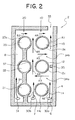
- FIG. 2 is a schematic horizontal sectional view of an internal combustion engine cylinder head 2 according to Embodiment 2 as seen from the opposite side of the cylinder block (not shown), that is, from above.
- the present invention is applied to a two-valve type internal combustion engine with three in-line cylinders.
- the components having the same constructions and functions as those of the cylinder head 1 are indicated by the same reference numerals, and a detailed description of such components will be omitted as appropriate.
- the cylinder head 2 is equipped with a cylinder head peripheral wall portion 4, an intake port row 10 consisting of intake ports 11, 12, and 13, an exhaust port row 20 consisting of exhaust ports 21, 22, and 23, inflow portions 30a, 30b, and 31 provided on the upstream side, and an outflow portion 33 provided on the downstream side.
- the intake ports 11, 12, and 13 are formed by intake port wall portions 11c, 12c, and 13c, respectively, and the exhaust ports 21 through 23 are formed integrally by an exhaust port wall portion 20c, one end on the upstream side of the exhaust port wall portion 20c being connected to the cylinder head peripheral wall portion 4.
- an exhaust side cooling path 8 is formed between the cylinder head peripheral wall portion 4 and the exhaust port wall portion 20c; an intake side cooling path 6 is formed between the cylinder head peripheral wall portion 4 and the intake side port wall portions 11c through 13c; and a central cooling path 7 is formed between the exhaust port wall portion 20c and the intake port wall portions 11c through 13c.
- a communication path 34a is provided between the intake port wall portions 11c and 12c, and a communication path 34b is provided between the intake port wall portions 12c and 13c.
- a flow rate control portion 35 which protrudes from the cylinder head peripheral wall portion 4 so as to narrow the intake side cooling path 6.
- cooling water flowing in from inflow portions 30a and 30b flow in the directions of the arrows A2 and A1. Note that plenty of cooling water flows in the direction of the arrow A2, where the flow passage is wide and there is less flow resistance. Due to the flow rate control portion 35 situated on the downstream side, the inflow of the cooling water flowing in the direction of the arrow A2 toward the downstream side of the intake side cooling path 6 is restrained, and most of the cooling water flows into the communication path 34a.
- the portion where the flow in the direction of the arrow A4 is formed is the portion of the central cooling path 7 which is between the intake port wall portion 12c and the exhaust port wall portion 20c (hereinafter referred to as "central portion 37"), is the portion of the cylinder head 2 which is subject to generation of large thermal stress; due to the fact that the flow in the direction of the arrow A4 is promoted, a high flow rate portion where plenty of cooling water flows is formed in the central portion 37, and this central portion 37 is cooled efficiently.
- a part of the cooling water having passed the central portion 37 flows to the downstream side of the central cooling path 7 (i.e., flows in the directions of the arrows A6 and A8), and the remain thereof flows through the communication path 34b (in the direction of the arrow A5) before flowing downstream through the intake side cooling path 6 (in the direction of the arrow A7), whereby a low flow rate portion is formed in one of the end portions other than the central portion 37 of the central cooling path 7 situated on the downstream side. Then, the portions of cooling water from the directions of the arrows A8 and A7 join together to flow out to the exterior from the outflow portion 33.
- the cooling water flowing in from the inflow portion 31 flows in the direction of the arrow B1 and flows downstream through the exhaust side cooling path 8 (in the direction of the arrow B2) before joining the cooling water from the directions of the arrows A6 and A7 and flowing out to the exterior from the outflow portion 33.
- the cylinder head 2 for a two-valve type internal combustion engine with three cylinders it is possible to efficiently cool the central portion of the cylinder head; further, the cooling water flow rate is appropriately distributed throughout the cylinder head as a whole, whereby it is possible to provide an internal combustion engine cylinder head cooling structure capable of enhancing cooling efficiency.
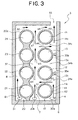
- FIG. 3 is a schematic horizontal sectional view of an internal combustion engine cylinder head 3 according to Embodiment 3 as seen from the opposite side of the cylinder block (not shown), that is, from above.
- the present invention is applied to a four-valve type internal combustion engine with two cylinders. Note that, in the description of the embodiment, the components having the same constructions and functions as those of the cylinder heads 1 and 2 are indicated by the same reference numerals, and a description of such components will be omitted as appropriate.
- the cylinder head 3 is equipped with a cylinder head peripheral wall portion 4, an intake port row 10 consisting of intake ports 11, 12, 13 and 14, an exhaust port row 20 consisting of exhaust ports 21, 22, 23 and 24, inflow portions 30a, 30b, and 31 provided on the upstream side of a cooling path 5, and an outflow portion 33 provided on the downstream side of the cooling path 5.
- the intake ports 11 through 14 are formed by intake port wall portions 11c, 12c, 13c and 14c, respectively, and the exhaust port wall portions 21 through 24 are formed integrally by an exhaust port wall portion 20c, one end on the upstream side of the exhaust port wall portion 20c being connected to the cylinder head peripheral wall portion 4. Note that, the intake ports 11 and 12 and the exhaust ports 21 and 22, and the intake ports 13 and 14 and the exhaust ports 23 and 24 correspond to one cylinder, respectively.
- flow rate control portions 35a and 35b which protrude from the cylinder head peripheral wall portion 4 so as to narrow the intake side cooling path 6.
- cooling water flowing in from inflow portions 30a and 30b flow in the directions of the arrows A2 and A1. Note that plenty of cooling water flows in the direction of the arrow A2, where the flow passage is wide and there is less flow resistance. Due to the flow rate control portion 35a situated on the downstream side, the inflow of the cooling water flowing in the direction of the arrow A2 toward the downstream side of the intake side cooling path 6 is restrained, and most of the cooling water flows into the communication path 34a.
- the portion where the flow in the direction of the arrow A4 is formed and the portion where the flow in the direction of the arrow A5 is formed is the portion of the central cooling path 7 surrounded by the intake port wall portions 12c and 13c and the exhaust port wall portion 20c (hereinafter referred to as the "central portion 37"), is the portion of the cylinder head 3 which is subject to generation of large thermal stress; through the promotion of this cooling water flow, a high flow rate portion where plenty of cooling water flows is formed in the central portion 37, and this central portion 37 is cooled efficiently. That is, due to the flow rate control portion 35a on the upstream side and the flow rate control portion 35b on the downstream side, it is possible to guide the cooling water such that sufficient cooling water flows to the central portion 37.
- a part of the cooling water having passed the central portion 37 flows to the downstream side of the central cooling path 7 (i.e., flows in the directions of the arrows A7 and A8), and the remain thereof flows through the communication path 34c (in the direction of the arrow A6) before flowing downstream through the intake side cooling path 6 (in the direction of the arrow A9), whereby a low flow rate portion is formed in one of the end portions other than the central portion 37 of the central cooling path 7 situated on the downstream side. Then the portions of cooling water from the directions of the arrows A8 and A9 join together to flow out to the exterior from the outflow portion 33.
- the cooling water flowing in from the inflow portion 31 flows in the direction of the arrow B1 and flows downstream through the exhaust side cooling path 8 (in the direction of the arrow B2) before joining the cooling water from the directions of the arrows A7 and A9 and flows out to the exterior from the outflow portion 33.
- the cylinder head 3 for a four-valve type internal combustion engine with two cylinders it is possible to efficiently cool the central portion of the cylinder head; further, the cooling water flow rate is appropriately distributed throughout the cylinder head as a whole, whereby it is possible to provide an internal combustion engine cylinder head cooling structure capable of enhancing cooling efficiency.
- the communication means is formed, by means of which cooling liquid is guided to the central portion, and, through this communication means, the cooling liquid flowrate in the central portion is increased with respect to the end portions, so that the flow resistance is high between the intake port and the exhaust port and, further, it is possible to efficiently cool the cylinder head central portion, which is subject to generation of thermal stress.
- the central portion which is subject to generation of thermal stress, can be efficiently cooled and, further, the cooling liquid flow rate is appropriately distributed throughout the cylinder head, whereby it is possible to provide a cylinder head cooling structure for an internal combustion engine with enhanced cooling efficiency.
- the flow rate control portion is provided in at least one of the intake side cooling path and the exhaust side cooling path, so that a high flow rate portion is formed in the central cooling path
- the communication means consists of a plurality of communication paths and one of the plurality of communication paths is provided on the downstream side of the flow rate control portion, so that cooling liquid in the central portion is caused to flow into the communication path, forming a low flow rate portion on the downstream side of the communication path of the central cooling path, cooling liquid is reliably caused to flow through the central portion, which is subject to generation of thermal stress, and it is possible to easily realize the bypassing of the end portions, which offer high low resistance but do not always require a large amount of cooling liquid.
- the central portion of the cylinder head can be efficiently cooled, and further, the cooling liquid flow rate is appropriately distributed throughout the cylinder head, whereby it is possible to provide a cylinder head cooling structure for an internal combustion engine which can attain an enhancement in cooling efficiency.
- the inflow portion has a plurality of holes, at least one of which is provided on the upstream side of the flow rate control portion, and is an intermediate inflow portion forming a flow path allowing cooling liquid to flow to the central cooling path through the communication path, it is possible to more effectively urge cooling liquid to flow toward the central portion through the communication path.
- the cylinder head is applied to an internal combustion engine in which each combustion chamber has two intake ports and two exhaust ports and in which not less than three cylinders are arranged, even in the case of a cylinder head for an internal combustion engine with a large number of intake ports and exhaust ports, such as a four-valve type one with not less than three cylinders, it is possible to efficiently cool the central portion of the cylinder head; further, the cooling liquid flow rate is appropriately distributed throughout the cylinder head, whereby it is possible to provide a cylinder head cooling structure for an internal combustion engine with enhanced cooling efficiency.
Abstract
Description
- The present invention relates to a cylinder head cooling structure which causes cooling water to flow through a cooling water path formed in the cylinder head of an internal combustion engine, from an inflow portion to an outflow portion, thereby cooling the cylinder head heated by a combustion chamber.
- The cylinder head of an internal combustion engine is provided with a cooling water path for cooling against heating by the combustion chamber. Usually, this cooling water path is formed such that cooling water can flow around wall portions forming an intake port and an exhaust port.
- However, due to the restriction regarding the arrangement of the intake port, the exhaust port, the fuel injection valve insertion opening, etc., it is difficult to form a cooling water path having a sufficient space between the intake port and the exhaust port. Further, the inter-port portion between the intake port and the exhaust port is particularly likely to attain high temperature. Thus, when cooling water is caused to flow from the inflow portion provided at one end of the cylinder head to the outflow portion provided at the other end side thereof, a sufficient amount of cooling water does not flow through the portion between the intake port and the exhaust port, where the flow resistance is high, and it is difficult to efficiently cool the inter-port portion, which is subject to high temperature as stated above.
- JP 5-86969 A, for example, discloses a structure in which, in order to pass as much cooling water as possible through the portion between the intake port and the exhaust port and to cool the inter-port portion subject to high temperature, the cooling water path is divided by a partition wall for each combustion chamber, and a protruding wall for guiding the flowing direction of cooling water toward the inter-port portion is formed at some midpoint of the partition wall.
- However, in the above-mentioned structure, in which the cooling water path is subdivided for each combustion chamber and in which cooling water is guided to the inter-port portion subject to high temperature, an excessive pressure loss is generally likely to occur, and the structure becomes rather complicated. As a result, it is highly possible that the supply of a sufficient amount of cooling water to the inter-port portion will be impaired.
- Further, as has been found out before the completion of the present invention, in an internal combustion engine in which a plurality of cylinders are arranged, there is relatively little constraint in the portions near the ends of the cylinder row, so that, as compared with the inter-port portions of the cylinders situated at the positions other than the ends, the inter-port portions at the ends are less subject to generation of thermal stress, and it is not always necessary to pass a large amount of cooling water therethrough. From this point of view also, it has been suggested in completing the present invention that it is possible to distribute a cooling water flow rate appropriately throughout the cylinder head and to cool more efficiently the cylinder head central portion which is subject to generation of large thermal stress.
- In view of the above situation, it is an object of the present invention to provide a cylinder head cooling structure for an internal combustion engine which is capable of efficiently cooling the central portion of the cylinder head and which appropriately distributes the cooling water flow rate throughout the cylinder head, whereby it is possible to achieve an improvement in cooling efficiency.
- To achieve the above object, there is provided, in accordance with the present invention, a cylinder head cooling structure for an internal combustion engine in which a cooling liquid is caused to flow from an inflow portion to an outflow portion through a cooling liquid path formed in the cylinder head of the internal combustion engine equipped with a port row in which at least one intake valve and at least one exhaust valve are arranged, so that the cylinder head heated by a combustion chamber is cooled, characterized in that: the cooling liquid path comprising an intake side cooling path formed between an intake port wall portion forming an intake port row and a cylinder head peripheral wall portion, an exhaust side cooling path formed between an exhaust port wall portion forming an exhaust port row and a cylinder head peripheral wall portion, and a central cooling path formed between the intake port wall portion and the exhaust port wall portion; and a communication means communicating the central cooling path with at least one of the intake side cooling path and the exhaust side cooling path is formed, that a high flow rate portion and a low flow rate portion are formed in the central cooling path through the intermediation of the communication means, and that the proportion of the longitudinal length of the cylinder head of the high flow rate portion formed in a central portion of the central cooling path with respect to the longitudinal length of the cylinder head of the central portion of the central cooling path is larger than the proportion of the longitudinal length of the cylinder head of the high flow rate portion formed in the end portions other than the central portion of the central cooling path with respect to the length of the end portions other than the central portion of the central cooling path.
- The internal combustion engine equipped with a port row in which at least one intake valve and at least one exhaust valve are arranged includes a single-cylinder engine and a multi-cylinder internal combustion engine, and also includes a two-valve system in which each cylinder has one intake valve and one exhaust valve and a four-valve system in which each cylinder has two intake valves and two exhaust valves, etc.
- Here, the communication means may be one having only one communication path or one having a plurality of communication paths.
- Then, in the central cooling path, the high flow rate portion and the low flow rate portion are determined in correspondence with upstream side and downstream side portions of the communication path when there is only one communication path, and determined in correspondence with each of the portion between adjacent communication paths, the portion between the uppermost-stream side communication path and the upstream end, and the portion between the downmost-stream side communication path and the downstream end when there are a plurality of communication paths.
- In the case in which there are a plurality of communication paths, when cooling liquid flows into the central cooling path from the communication path on the upstream side of the portion between adjacent communication paths, the portion between the communication path into which cooling liquid flows and the adjacent communication path is the high flow rate portion; when cooling liquid flows into the central cooling path from the downmost-stream side communication path, the portion between the downmost-stream side communication path and the downstream end is the high flow rate portion; when no cooling liquid flows into the central cooling path from the communication path on the upstream side of the portion between adjacent communication paths, the portion between the communication path into which no cooling liquid flows and the adjacent communication path is the low flow rate portion; and when no cooling liquid flows into the central cooling path from the downmost-stream side communication path, the portion between the downmost-stream side communication path and the downstream end is the low flow rate portion.
- Regarding the portion between the upstream end of the central cooling path and the adjacent communication path, when cooling liquid flows into the central cooling path from the communication path adjacent to the upstream end, the portion between the upstream end and the communication path is the low flow rate portion, and when no cooling liquid flows into the central cooling path from the communication path, the portion between the upstream end and the communication path is the high flow rate portion.
- The term "central portion" used in Claim 1 will be defined as follows:
- First, in the case of an engine with three or more cylinders arranged in series, the central cooling path of the portion adjacent to the cylinders other than those at the ends will be referred to as the central portion.
- For example, as described in relation to Embodiment 1, in the case of an engine with four cylinders, the central cooling path of the portion adjacent to the central two cylinders other than those at the ends is the central portion.
- In the case of
Embodiment 2 shown in Fig. 3, which consists of a four-valve type engine with two in-line cylinders in which a communication path is formed between the two intake port wall portions formed on the respective cylinders, the two end intake ports of the four intake ports are excluded, and the central cooling path of the portion adjacent to the remaining two central intake ports is the central portion. - It is stated in Claim 1 that "the proportion of the longitudinal length of the cylinder head of the high flow rate portion formed in a central portion of the central cooling path with respect to the longitudinal length of the cylinder head of the central portion (37) of the central cooling path is larger than the proportion of the longitudinal length of the cylinder head of the high flow rate portion formed in the end portions other than the central portion of the central cooling path with respect to the length of the end portions other than the central portion of the central cooling path. " This means that as in, for example, Embodiment 1, when all the central portion of the central cooling path is a high flow rate portion, and all the end portions other than the central portion of the central cooling path are a low flow rate portion, "the proportion of the longitudinal length of the cylinder head of the high flow rate portion formed in the central portion of the central cooling path with respect to the longitudinal length of the cylinder head of the central portion (37) of the central cooling path" is "100%", and "the proportion of the longitudinal length of the cylinder head of the high flow rate portion formed in the end portions other than the central portion of the central cooling path with respect to the length of the end portions other than the central portion of the central cooling path" is "0%"; the proportion of the longitudinal length of the cylinder head of the high flow rate portion formed in the central portion of the central cooling path with respect to the longitudinal length of the cylinder head of the central portion of the central cooling path is larger than the proportion of the longitudinal length of the cylinder head of the high flow rate portion formed in the end portions other than the central portion of the central cooling path with respect to the length of the end portions other than the central portion of the central cooling path.
- Further, when the proportion of the longitudinal length of the cylinder head of the high flow rate portion formed in the central portion of the central cooling path with respect to the longitudinal length of the cylinder head of the central portion of the central cooling path is larger than the proportion of the longitudinal length of the cylinder head of the high flow rate portion formed in the end portions other than the central portion of the central cooling path with respect to the length of the end portions other than the central portion of the central cooling path, only a portion of the central portion of the central cooling path may be the high flow rate portion, or a portion of the end portions other than the central portion of the central cooling path may be the high flow rate portion.
- In this construction, there is formed a communication means by means of which cooling liquid is guided to the central portion, and, through this communication means, the cooling liquid flow rate in the central portion is increased with respect to the end portions, so that the flow resistance is high between the intake port and the exhaust port and, further, it is possible to efficiently cool the cylinder head central portion, which is subject to generation of thermal stress.
- Further, in this construction, for the end portions to which it is not always necessary to supply a large amount of cooling liquid, detouring to the intake side cooling path or the exhaust side cooling path is possible through the communication means, whereby, regarding the central cooling path with high flow resistance, it is possible to chiefly cool the central portion, which is subject to generation of thermal stress. That is, the central portion is efficiently cooled, and the end portions which offer high flow resistance but do not always require a large amount of cooling liquid are bypassed, whereby in the cooling liquid path as a whole, it is possible to decrease the pressure loss and increase the flow rate. Thus, the cooling water flow rate is appropriately distributed throughout the cylinder head, thereby making it possible to provide a cylinder head cooling structure for an internal combustion engine capable of enhancing cooling efficiency.
- Preferably, the present invention may provide the cylinder head cooling structure for an internal combustion engine is characterized in that the high flow rate portion accounts for the central portion, and the low flow rate portion accounts for the end portions.
- In this construction, the central portion, which is subject to generation of thermal stress, can be efficiently cooled and, further, the cooling liquid flow rate is appropriately distributed throughout the cylinder head, whereby it is possible to provide a cylinder head cooling structure for an internal combustion engine with enhanced cooling efficiency.
- Preferably, the present invention may provide a cylinder head cooling structure for an internal combustion engine in which a cooling liquid is caused to flow from an inflow portion to an outflow portion through a cooling liquid path formed in the cylinder head of the internal combustion engine equipped with a port row in which at least one intake valve and at least one exhaust valve are arranged, so that the cylinder head heated by a combustion chamber is cooled, characterized in that: the cooling liquid path comprising an intake side cooling path formed between an intake port wall portion forming an intake port row and a cylinder head peripheral wall portion, an exhaust side cooling path formed between an exhaust port wall portion forming an exhaust port row and a cylinder head peripheral wall portion, and a central cooling path formed between the intake port wall portion and the exhaust port wall portion; and a communication means communicating the central cooling path with at least one of the intake side cooling path and the exhaust side cooling path is formed, a high flow rate portion and two low flow rate portions are formed in the central cooling path through the intermediation of the communication means, and the high flow rate portion and two low flow rate portions arranged in order of the low flow rate portion, the high flow rate portion, the low flow rate portion from upstream toward downstream of the central cooling path.
- Preferably, the present invention may provide the cylinder head cooling structure for an internal combustion engine is characterized in that regarding at least one of the plurality of communication paths constituting the communication means, a flow rate control portion is provided in the intake side cooling path or the exhaust side cooling path communicating with the central cooling path through the communication path at a position on the downstream side of the communication path, so that cooling liquid is caused to flow into the central cooling path through the communication path, forming the high flow rate portion on the downstream side of the communication path of the central cooling path.
- In this construction, it is possible to achieve the same effect as that of the other aspects of the invention with a simple construction in which a flow rate control portion is provided at some midpoint of the intake side cooling path or the exhaust side cooling path communicating with the central cooling path. Regarding the flow rate control portion, there is no particular restriction in configuration and it may be formed, for example, by causing a part of the port wall portion or the cylinder head peripheral wall portion to protrude, or providing at some midpoint of the cooling path a portion separate from the wall portion which narrows the flow path; various designs are possible which narrow or cut off the cooling path.
- Preferably, the present invention may provide the cylinder head cooling structure for an internal combustion engine is characterized in that a flow rate control portion is provided in at least one of the intake side cooling path and the exhaust side cooling path, so that a high flow rate portion is formed in the central cooling path, and one of the plurality of communication paths constituting the communication means is provided on the downstream side of the flow rate control portion, so that cooling liquid in the central portion is caused to flow into the communication path, forming a low flow rate portion on the downstream side of the communication path of the central cooling path.
- In this construction, cooling liquid is reliably caused to flow through the central portion, which is subject to generation of thermal stress, and it is possible to easily realize the bypassing of the end portions, which offer high flow resistance but do not always require a large amount of cooling liquid. Thus, the central portion of the cylinder head can be efficiently cooled, and further, the cooling liquid flow rate is appropriately distributed throughout the cylinder head, whereby it is possible to provide a cylinder head cooling structure for an internal combustion engine which can attain an enhancement in cooling efficiency.
- Preferably, the present invention may provide the cylinder head cooling structure for an internal combustion engine is characterized in that the inflow portion has a plurality of holes, at least one of which is provided on the upstream side of the flow rate control portion, and is an intermediate inflow portion forming a flow path allowing cooling liquid to flow to the central cooling path through the communication path.
- In this construction, by providing an intermediate inflow portion on the upstream side of the flow rate control portion, it is possible to more effectively urge cooling liquid to flow toward the central portion through the communication path. Thus, as compared with the other construction, it is possible to cool the central portion of the cylinder head more efficiently.
- Preferably, the present invention may provide the cylinder head cooling structure for an internal combustion engine is characterized in that the cylinder head is applied to an internal combustion engine in which each combustion chamber has two intake ports and two exhaust ports and in which not less than three cylinders are arranged.
- In this construction, even in the case of a cylinder head for an internal combustion engine with a large number of intake ports and exhaust ports, such as a four-valve type one with not less than three cylinders, it is possible to efficiently cool the central portion of the cylinder head; further, the cooling liquid flow rate is appropriately distributed throughout the cylinder head, whereby it is possible to provide a cylinder head cooling structure for an internal combustion engine with enhanced cooling efficiency.
- In the accompanying drawings:
- Fig. 1 is a horizontal sectional view of a cylinder head of an internal combustion engine according to Embodiment 1 of the present invention;
- Fig. 2 is a horizontal sectional view of a cylinder head of
an internal combustion engine according to
Embodiment 2 of the present invention; and - Fig. 3 is a horizontal sectional view of a cylinder head of
an internal combustion engine according to
Embodiment 3 of the present invention. -
- Embodiments of the present invention will now be described with reference to the drawings. First, Embodiment 1 will be described.
- Fig. 1 is a horizontal sectional view of the cylinder head 1 of an internal combustion engine according to Embodiment 1 as seen from the opposite side to the cylinder block (not shown), that is, as seen from above. The cylinder head 1 is applied to a four-valve type internal combustion engine with four in-line cylinders. The cylinder head 1 is formed as an integral unit in the form of a casting of aluminum alloy.
- The cylinder head 1 has two intake ports for each cylinder:
intake ports exhaust ports intake port row 10 and anexhaust port row 20. Theintake port row 10 and theexhaust port row 20 are adjacent to each other. In the following description, all the intake ports of theintake port row 10 will also be collectively referred to as theintake ports 10, and all the exhaust ports of theexhaust port row 20 will also be collectively referred to as theexhaust ports 20. - Regarding the
intake ports 10, they are formed by intakeport wall portions exhaust ports 20, they are formed by an exhaustport wall portion 20c which integrally forms all the exhaust ports 21a through 24b. Theintake ports 10 andexhaust ports 20 thus formed are open on the lower side in direction of combustion chambers (not shown). These ports are formed through punching by means of cores when forming the cylinder head 1 by casting or the like. - Between the paired intake ports and on the side facing the
exhaust port row 20, the intakeport wall portions valve insertion holes - Then, between a cylinder head
peripheral wall portion 4, surrounding theintake ports 10 and theexhaust ports 20 and constituting the contour of the cylinder head 1, and the periphery of the intake port wall portions 11c through 14c and of the exhaustport wall portion 20c, there is formed acooling water path 5 serving as a cooling liquid path for cooling the cylinder head 1 heated by the combustion chambers (not shown). The coolingwater path 5 is formed through punching by means of a core when forming the cylinder head 1 by casting or the like; the formation process is effected such that a part of the intake port wall portions or of the exhaust port wall portion is connected with the cylinder headperipheral wall portion 4. In the cylinder head 1 shown in Fig. 1, an example is shown in which the exhaustport wall portion 20c is connected to theperipheral wall portion 4. - The cooling
water path 5 is equipped with an intakeside cooling path 6 formed between the intake port wall portions 11c through 14c and the cylinder headperipheral wall portion 4, an exhaustside cooling path 8 formed between the exhaustport wall portion 20c and the cylinder headperipheral wall portion 4, and acentral cooling path 7 formed between the intake port wall portions 11c through 14c and the exhaustport wall portion 20c. - As for the cooling liquid, cooling water is caused to flow through the cooling
water path 5 formed as described above, from inflow portions to outflow portions, whereby the cylinder head 1 is cooled. There are provided a plurality of inflow portions: intakeside inflow portions side cooling path 6 or thecentral cooling path 7, an exhaustside inflow portion 31 provided in the vicinity of the exhaust port 21a on the uppermost stream side of the exhaustside cooling path 8, andintermediate inflow portions side cooling path 6. These inflow portions are formed as holes communicating with cooling passages formed in the cylinder block (not shown). Regarding anoutflow portion 33, it is formed at the position substantially on the downmost-stream side of the intakeside cooling path 6 so as to form in a part of the cylinder head peripheral wall portion 4 a hole for communication with the exterior. Note that, apart from the cooling water, the cooling liquid may be some other cooling liquid, such as cooling oil. - Then, between the
central cooling path 7 and the intakeside cooling path 6, there are provided a plurality of communication passages formed so as to be narrow between the intake port wall portions and adapted to communicate thecentral cooling path 7 with the intakeside cooling path 6. That is, acommunication path 34a is formed between the intakeport wall portions 11c and 12c, acommunication path 34b is formed between thewall portions communication path 34c is formed between thewall portions - Further, at midpoints of the intake
side cooling path 6 communicating with thecentral cooling path 7, there are provided a plurality of flow rate control portions. The flow rate control portions restrain inflow of cooling water into the intakeside cooling path 6, and are formed so as to protrude from the cylinder headperipheral wall portion 4 toward the intake port wall portion. That is, in the cylinder head 1 shown in Fig. 1, flowrate control portions peripheral wall portion 4 respectively toward the portions between paired intake ports of the intakeport wall portions - In the vicinity of the flow
rate control portions intermediate inflow portions 32b through 32d as described above and further, in the vicinity of the intake port 11b, theintermediate inflow portion 32a is provided. That is, theintermediate inflow portion 32a is provided at the position where cooling water comes out from the upstream side of thecommunication path 34a; theintermediate inflow portion 32b is provided somewhat nearer to the upstream side than the flowrate control portion 35a and in the vicinity of the intake port 12a; theintermediate inflow portion 32c is provided on the downstream side of the flowrate control portion 35a and on the upstream side of thecommunication path 34b; and theintermediate inflow portion 32d is provided on the upstream side of the flowrate control portion 35b and in the vicinity of the intake port 13a. These inflow portions cause inflow such that cooling water comes out at midpoints of the intakeside cooling path 6. - The cooling structure for the cylinder head 1 is as described above. Next, the cooling water flowing condition and the cooling action in this cylinder head 1 will be described.
- First, cooling water flows into the cylinder head 1 from the inflow portions. As described above, there are provided a plurality of inflow portions; of these, cooling water flows in mainly from the intake
side inflow portions side inflow portion 31 rather than from theintermediate inflow portions 32a through 32d. Of course, cooling water does flow in from theintermediate inflow portions 32a through 32d, too. - The cooling water flowing in from the intake
side inflow portion 30a flows mainly along the intakeside cooling path 6. The flowing direction is indicated by the arrow A2. A part of the cooling water flowing in from the intakeside inflow portion 30b flows toward thecentral cooling path 7 as indicated by the arrow A1. However, in thecentral flow path 7, the flow passage space is small and the flow resistance is high, so that, as compared with the intakeside cooling path 6, it does not easily allow cooling water to flow in. The remain portion of the cooling water flowing in from the intakeside inflow portion 30b joins the cooling water flowing in from the intakeside inflow portion 30a and flows also into the intakeside cooling path 6. It is to be noted that there is provided not only the intakeside inflow portion 30a but also the intakeside inflow portion 30b, whereby the inflow to thecentral cooling path 7 is promoted. In order that the structures, etc. of the cooling paths may be easily understood, the dimensions and configurations as given in Fig. 1 are somewhat different from the actual ones. - The cooling water flowing in from the intake
side inflow portion 30a flows in the direction of the arrow A2, and joins at some midpoint the cooling water flowing in from theintermediate inflow portion 32a and further flows toward the downstream side. On the downstream side of the intakeside cooling path 6, there is provided the flowrate control portion 35a, and the pressure loss of aflow resistance portion 6b constituting a flow path formed between the flowrate control portion 35a and the intakeport wall portion 12c is large, so that the inflow of cooling water from the upstream side into aflow path 6a constituting the intakeside cooling path 6 adjacent to the intake port 12a is restrained. - And, cooling water also flows in from the
intermediate inflow portion 32b situated on the upstream side of the flowrate control portion 35a, so that the inflow of cooling water from the upstream side into theflow path 6a is restrained. Most of the cooling water flowing in from theintermediate inflow portion 32b is caused to flow in such a direction that the flow resistance on the opposite side to theflow resistance portion 6b on the downstream side is low, that is, in the direction of the arrow A6. - In this way, the inflow into the
flow path 6a is restrained, and the cooling water flowing from the upstream side and the cooling water flowing in from theintermediate inflow portion 32a join together and flow into thecommunication path 34a. The cooling water flowing into thecommunication path 34a flow into thecentral cooling path 7 as indicated by the arrow A5 after passing thecommunication path 34a. At this time, it joins the cooling water coming from the upstream side of thecentral cooling path 7 in the direction of the arrow A3. Thus, the portions of cooling water flowing in the directions of the arrows A3 and A5 and joining together flow into a flow path 7a constituting thecentral cooling path 7 formed by the intakeport wall portion 12c and the exhaustport wall portion 20c. - Together with a flow path 7b described below, this flow path 7a forms the portion situated at the center of the port row (hereinafter referred to as "
central portion 37"), which is a portion subject to generation of excessive thermal stress. Thus, due to the fact that it is possible to realize a structure promoting cooling water flow toward the flow path 7a as described above, a high flow rate portion where plenty of cooling water flows is formed in the flow path 7a, that is, in thecentral portion 37, and it is possible to efficiently cool thecentral portion 37, thereby restraining generation of excessive thermal stress. As will be described below, this high flow rate portion is formed in thecentral portion 37 consisting of the flow paths 7a and 7b. - The cooling water flowing into the flow path 7a from the directions of the arrows A3 and A5 passes through the flow path 7a and flows in the direction of the arrow A7, and joins the cooling water flowing in from the
communication path 34b. The cooling water flowing into thecommunication path 34b comes flowing from theintermediate inflow portions side cooling path 6 . That is, due to the provision of the flowrate control portion 35b on the downstream side, most of the cooling water flowing in from theintermediate inflow portion 32c flows in the direction of the arrow A8, and, due to the provision of the flowrate control portion 35b on the downstream side, most of the cooling water flowing in from theintermediate inflow portion 32d flows in the direction of the arrow A10 on the upstream side. In this way, the portions of cooling water from the directions of the arrows A8 and A10 join together and flow into thecommunication path 34b, and, after passing thecommunication path 34b, flow in the direction of the arrow A9 before joining the cooling water from the direction of the arrow A7. - In this way, the cooling water from the directions of the arrows A7 and A9 flows into the flow path 7b formed between the intake
port wall portion 13c and the exhaustport wall portion 20c, that is, into the rear half of thecentral portion 37, so that a high flow rate portion where plenty of cooling water flows is also formed in the rear half of thecentral portion 37, and, like the flow path 7a, the flow path 7b is also efficiently cooled, thereby preventing thecentral portion 37 from attaining an excessively high temperature and restraining generation of excessive thermal stress. - A part of the cooling water passing through the flow path 7b flows downstream along the narrow central cooling path 7 (in the direction of the arrow A13), whereas the remain thereof flows into the
communication path 34c (in the direction of the arrow A11) and passes through thecommunication path 34c before flowing into the intake side cooling path 6 (in the direction of the arrow A12), whereby a low flow rate portion where a small amount of cooling water flows is formed in a flow path 7c which is on the downstream side of thecommunication path 34c and which is formed between the intakeport wall portion 14c and the exhaustport wall portion 20c. The cooling water having flowed to the downstream side of thecentral cooling path 7 by way of the flow path 7c flows out in the direction of the arrow A14, and the cooling water having flowed downstream through the intakeside cooling path 6 flows out in the direction of the arrow A15, and joins the cooling water coming from the exhaustside cooling path 8 as described below before flowing out to the exterior of the cylinder head 1 from theoutflow portion 33. - In addition, regarding the cooling water flowing through the exhaust
side cooling path 8, the cooling water flowing in from theinflow portion 31 situated on the uppermost stream side of the exhaustside cooling path 8 first flows in the direction of the arrow B1, and continues to flow downstream through the exhaustside cooling path 8, that is, through the passage between the exhaustport wall portion 20c and the cylinder headperipheral wall portion 4. Then, it flows out in the direction of the arrow B2 from the exhaustside cooling path 8, and joins the cooling water from the directions of the arrows A14 and A15 before flowing out to the exterior from theoutflow portion 33. The cooling water having flowed out to the exterior circulates through a radiator or the like (not shown), and is used for the cooling of the cylinder head 1 again. - As described above, in the internal combustion engine cylinder head cooling structure of Embodiment 1, the
communication path 34a, etc. through which cooling water is guided to thecentral portion 37 are formed; further, due to the flowrate control portion 35a, etc., the inflow of cooling water into the intakeside cooling path 6 is restrained, so that the inflow of cooling water into thecentral portion 37 through thecommunication path 34a, etc. is promoted, whereby a high flow rate portion is formed in thecentral portion 37 which offers high flow resistance between theintake port 10 and theexhaust port 20 and which is subject to generation of large thermal stress, thereby making it possible to efficiently cool thecentral portion 37. - Further, in this cylinder head 1, with respect to the flow path 7c that is on one downstream side of the end portions other than the
central portion 37 of thecentral cooling path 7, in which it is not always necessary to cause plenty of cooling water to flow, bypassing to the intakeside cooling path 6 is possible through thecommunication path 34c, whereby, regarding thecentral cooling path 7 involving high flow resistance, it is possible to chiefly cool thecentral portion 37 that is subject to generation of large thermal stress. That is, thecentral portion 37 is efficiently cooled, and the end portions of thecentral cooling path 7, which offer high flow resistance but do not always require plenty of cooling water, are bypassed, and a low flow rate portion is formed in this portion, making it possible to decrease the pressure loss of the coolingwater path 5 as a whole and increase the flow rate. Thus, the cooling water flow rate is appropriately distributed throughout the cylinder head, whereby it is possible to provide an internal combustion engine cylinder head cooling structure capable of enhancing cooling efficiency. Note that, in this cylinder head 1, a low flow rate portion is formed not only in the flow path 7c on the downstream side of thecentral portion 37 of the end portions but also on the upstream side of thecentral cooling portion 37 constituting the other end portion, that is, in theflow path 7d that is thecentral cooling path 7 formed between the intake port wall portion 11c and the exhaustport wall portion 20c. - While in the structure of the cylinder head 1 the intake
side cooling path 6 communicates with thecentral cooling path 7 through thecommunication path 34a, etc., this should not be construed restrictively. In the cylinder head 1 of Fig. 1, it is also possible, for example, to reverse the right and left sides. That is, it is also possible to adopt a construction in which the intake port wall portion is formed as an intake port wall portion integrally forming all the intake ports, one end on the upstream side thereof being connected to the cylinder head peripheral wall portion and the exhaustside cooling path 8 communicating with thecentral cooling path 7. Further, it is also possible to adopt a construction in which both the intakeside cooling path 6 and the exhaustside cooling path 8 communicate with thecentral cooling path 7. - Next, an internal combustion engine cylinder head cooling structure according to
Embodiment 2 will be described. Fig. 2 is a schematic horizontal sectional view of an internal combustionengine cylinder head 2 according toEmbodiment 2 as seen from the opposite side of the cylinder block (not shown), that is, from above. In thiscylinder head 2, the present invention is applied to a two-valve type internal combustion engine with three in-line cylinders. In the description of the embodiment, the components having the same constructions and functions as those of the cylinder head 1 are indicated by the same reference numerals, and a detailed description of such components will be omitted as appropriate. - The
cylinder head 2 is equipped with a cylinder headperipheral wall portion 4, anintake port row 10 consisting ofintake ports exhaust port row 20 consisting ofexhaust ports inflow portions outflow portion 33 provided on the downstream side. Theintake ports port wall portions exhaust ports 21 through 23 are formed integrally by an exhaustport wall portion 20c, one end on the upstream side of the exhaustport wall portion 20c being connected to the cylinder headperipheral wall portion 4. Then, an exhaustside cooling path 8 is formed between the cylinder headperipheral wall portion 4 and the exhaustport wall portion 20c; an intakeside cooling path 6 is formed between the cylinder headperipheral wall portion 4 and the intake side port wall portions 11c through 13c; and acentral cooling path 7 is formed between the exhaustport wall portion 20c and the intake port wall portions 11c through 13c. Further, between the intake port wall portions, there are provided communication paths communicating thecentral cooling path 7 with the intakeside cooling path 6. That is, acommunication path 34a is provided between the intakeport wall portions 11c and 12c, and acommunication path 34b is provided between the intakeport wall portions side cooling path 6 and at a position corresponding to the intakeport wall portion 12c, there is provided a flowrate control portion 35 which protrudes from the cylinder headperipheral wall portion 4 so as to narrow the intakeside cooling path 6. - The main directions in which cooling water flows in this
cylinder head 2 are indicated by arrows A1 through A8, B1 and B2. Cooling water flowing in frominflow portions rate control portion 35 situated on the downstream side, the inflow of the cooling water flowing in the direction of the arrow A2 toward the downstream side of the intakeside cooling path 6 is restrained, and most of the cooling water flows into thecommunication path 34a. Then, after flowing through thecommunication path 34a in the direction of the arrow A3, it joins the cooling water from the direction of the arrow A1 to flow in the direction of the arrow A4. The portion where the flow in the direction of the arrow A4 is formed, that is, the portion of thecentral cooling path 7 which is between the intakeport wall portion 12c and the exhaustport wall portion 20c (hereinafter referred to as "central portion 37"), is the portion of thecylinder head 2 which is subject to generation of large thermal stress; due to the fact that the flow in the direction of the arrow A4 is promoted, a high flow rate portion where plenty of cooling water flows is formed in thecentral portion 37, and thiscentral portion 37 is cooled efficiently. - A part of the cooling water having passed the
central portion 37 flows to the downstream side of the central cooling path 7 (i.e., flows in the directions of the arrows A6 and A8), and the remain thereof flows through thecommunication path 34b (in the direction of the arrow A5) before flowing downstream through the intake side cooling path 6 (in the direction of the arrow A7), whereby a low flow rate portion is formed in one of the end portions other than thecentral portion 37 of thecentral cooling path 7 situated on the downstream side. Then, the portions of cooling water from the directions of the arrows A8 and A7 join together to flow out to the exterior from theoutflow portion 33. - The cooling water flowing in from the
inflow portion 31 flows in the direction of the arrow B1 and flows downstream through the exhaust side cooling path 8 (in the direction of the arrow B2) before joining the cooling water from the directions of the arrows A6 and A7 and flowing out to the exterior from theoutflow portion 33. - As described above, also in the
cylinder head 2 for a two-valve type internal combustion engine with three cylinders, it is possible to efficiently cool the central portion of the cylinder head; further, the cooling water flow rate is appropriately distributed throughout the cylinder head as a whole, whereby it is possible to provide an internal combustion engine cylinder head cooling structure capable of enhancing cooling efficiency. - Finally, an internal combustion engine cylinder head cooling structure according to
Embodiment 3 will be described. Fig. 3 is a schematic horizontal sectional view of an internal combustionengine cylinder head 3 according toEmbodiment 3 as seen from the opposite side of the cylinder block (not shown), that is, from above. In thiscylinder head 3, the present invention is applied to a four-valve type internal combustion engine with two cylinders. Note that, in the description of the embodiment, the components having the same constructions and functions as those of thecylinder heads 1 and 2 are indicated by the same reference numerals, and a description of such components will be omitted as appropriate. - The
cylinder head 3 is equipped with a cylinder headperipheral wall portion 4, anintake port row 10 consisting ofintake ports exhaust port row 20 consisting ofexhaust ports inflow portions cooling path 5, and anoutflow portion 33 provided on the downstream side of thecooling path 5. The intake ports 11 through 14 are formed by intakeport wall portions port wall portions 21 through 24 are formed integrally by an exhaustport wall portion 20c, one end on the upstream side of the exhaustport wall portion 20c being connected to the cylinder headperipheral wall portion 4. Note that, theintake ports 11 and 12 and theexhaust ports intake ports exhaust ports - Then, between the cylinder head
peripheral wall portion 4 and the exhaustport wall portion 20c, there is formed an exhaustside cooling path 8; between the cylinder headperipheral wall portion 4 and the intake side port wall portions 11c through 14c, there is formed an intakeside cooling path 6; and, between the exhaustport wall portion 20c and the intake port wall portions 11C through 14c, there is formed acentral cooling path 7. Further, between the intake port wall portions, there are provided communication paths communicating thecentral cooling path 7 with the intakeside cooling path 6. That is, acommunication path 34a is provided between the intakeport wall portions 11c and 12c, acommunication path 34b is provided between the intakeport wall portions communication path 34c is provided between the intakeport wall portions side cooling path 6 and at positions corresponding to the intakeport wall portions rate control portions peripheral wall portion 4 so as to narrow the intakeside cooling path 6. - The main directions in which cooling water flows in this
cylinder head 3 are indicated by arrows A1 through A9, B1 and B2. Cooling water flowing in frominflow portions rate control portion 35a situated on the downstream side, the inflow of the cooling water flowing in the direction of the arrow A2 toward the downstream side of the intakeside cooling path 6 is restrained, and most of the cooling water flows into thecommunication path 34a. Then, after flowing through thecommunication path 34a in the direction of the arrow A3, it joins the cooling water from the direction of the arrow A1 to flow in the direction of the arrow A4. Remain of the cooling water flows between the flowrate control portion 35a and the intakeport wall portion 12c, along the intakeside cooling path 6. - Further, on the downstream side of the flow
rate control portion 35a, there is also provided the flowrate control portion 35b, so that the inflow of cooling water into the intakeside cooling path 6 in between is restrained. Thus most of the cooling water from the direction of the arrow A4 flows in the direction of the arrow A5. The portion where the flow in the direction of the arrow A4 is formed and the portion where the flow in the direction of the arrow A5 is formed, that is, the portion of thecentral cooling path 7 surrounded by the intakeport wall portions port wall portion 20c (hereinafter referred to as the "central portion 37"), is the portion of thecylinder head 3 which is subject to generation of large thermal stress; through the promotion of this cooling water flow, a high flow rate portion where plenty of cooling water flows is formed in thecentral portion 37, and thiscentral portion 37 is cooled efficiently. That is, due to the flowrate control portion 35a on the upstream side and the flowrate control portion 35b on the downstream side, it is possible to guide the cooling water such that sufficient cooling water flows to thecentral portion 37. - A part of the cooling water having passed the
central portion 37 flows to the downstream side of the central cooling path 7 (i.e., flows in the directions of the arrows A7 and A8), and the remain thereof flows through thecommunication path 34c (in the direction of the arrow A6) before flowing downstream through the intake side cooling path 6 (in the direction of the arrow A9), whereby a low flow rate portion is formed in one of the end portions other than thecentral portion 37 of thecentral cooling path 7 situated on the downstream side. Then the portions of cooling water from the directions of the arrows A8 and A9 join together to flow out to the exterior from theoutflow portion 33. - The cooling water flowing in from the
inflow portion 31 flows in the direction of the arrow B1 and flows downstream through the exhaust side cooling path 8 (in the direction of the arrow B2) before joining the cooling water from the directions of the arrows A7 and A9 and flows out to the exterior from theoutflow portion 33. - As described above, also in the
cylinder head 3 for a four-valve type internal combustion engine with two cylinders, it is possible to efficiently cool the central portion of the cylinder head; further, the cooling water flow rate is appropriately distributed throughout the cylinder head as a whole, whereby it is possible to provide an internal combustion engine cylinder head cooling structure capable of enhancing cooling efficiency. - The embodiments of the present invention are as described above. The above embodiments, however, should not be construed restrictively. For example, the following modifications are possible.
- (1) While in the above embodiments the present invention is applied to four-valve/four-cylinder, two-valve/three-cylinder, and four-valve/two-cylinder internal combustion engines, this should not be construed restrictively. The present invention is applicable to any type of internal combustion engine as long as it is equipped with a port row in which a plurality of intake valves and exhaust valves are arranged.
- (2) While in the above embodiments each flow rate control portion partly protrudes from the cylinder head peripheral wall portion, this should not be construed restrictively. For example, it is also possible to form the flow rate control portion as a continuous portion extending along the cylinder head peripheral wall portion or the port wall portion and having a length approximately corresponding to the central portion of the central cooling path.
- (3) Regarding the communication paths, it is not always necessary to provide a plurality of them; for example, when the length of the port row in the valve arrangement direction is small, it is possible to provide only one communication path guiding inflow into the central cooling path on the upstream side thereof.
-
- In the invention according to the present invention, the communication means is formed, by means of which cooling liquid is guided to the central portion, and, through this communication means, the cooling liquid flowrate in the central portion is increased with respect to the end portions, so that the flow resistance is high between the intake port and the exhaust port and, further, it is possible to efficiently cool the cylinder head central portion, which is subject to generation of thermal stress.
- Further, in this construction, for the end portions to which it is not always necessary to supply a large amount of cooling liquid, detouring to the intake side cooling path or the exhaust side cooling path is possible through the communication means, whereby, regarding the central cooling path with high flow resistance, it is possible to chiefly cool the central portion, which is subject to generation of thermal stress. That is, the central portion is efficiently cooled, and the end portions which offer high flow resistance but do not always require a large amount of cooling liquid are bypassed, whereby in the cooling liquid path as a whole, it is possible to decrease the pressure loss and increase the flow rate. Thus, the cooling water flow rate is appropriately distributed throughout the cylinder head, thereby making it possible to provide a cylinder head cooling structure for an internal combustion engine capable of enhancing cooling efficiency.
- Since the high flow rate portion accounts for the central portion, and the low flow rate portion accounts for the end portions, the central portion, which is subject to generation of thermal stress, can be efficiently cooled and, further, the cooling liquid flow rate is appropriately distributed throughout the cylinder head, whereby it is possible to provide a cylinder head cooling structure for an internal combustion engine with enhanced cooling efficiency.
- In the invention in which a flow rate control portion is provided at some midpoint of the intake side cooling path or the exhaust side cooling path communicating with the central cooling path, though a simple construction, it is possible to achieve the same effect as the invention in claim 1.
- Since the flow rate control portion is provided in at least one of the intake side cooling path and the exhaust side cooling path, so that a high flow rate portion is formed in the central cooling path, and the communication means consists of a plurality of communication paths and one of the plurality of communication paths is provided on the downstream side of the flow rate control portion, so that cooling liquid in the central portion is caused to flow into the communication path, forming a low flow rate portion on the downstream side of the communication path of the central cooling path, cooling liquid is reliably caused to flow through the central portion, which is subject to generation of thermal stress, and it is possible to easily realize the bypassing of the end portions, which offer high low resistance but do not always require a large amount of cooling liquid. Thus, the central portion of the cylinder head can be efficiently cooled, and further, the cooling liquid flow rate is appropriately distributed throughout the cylinder head, whereby it is possible to provide a cylinder head cooling structure for an internal combustion engine which can attain an enhancement in cooling efficiency.
- Since the inflow portion has a plurality of holes, at least one of which is provided on the upstream side of the flow rate control portion, and is an intermediate inflow portion forming a flow path allowing cooling liquid to flow to the central cooling path through the communication path, it is possible to more effectively urge cooling liquid to flow toward the central portion through the communication path. Thus, as compared with the other construction, it is possible to cool the central portion of the cylinder head more efficiently.
- Since the cylinder head is applied to an internal combustion engine in which each combustion chamber has two intake ports and two exhaust ports and in which not less than three cylinders are arranged, even in the case of a cylinder head for an internal combustion engine with a large number of intake ports and exhaust ports, such as a four-valve type one with not less than three cylinders, it is possible to efficiently cool the central portion of the cylinder head; further, the cooling liquid flow rate is appropriately distributed throughout the cylinder head, whereby it is possible to provide a cylinder head cooling structure for an internal combustion engine with enhanced cooling efficiency.
Claims (16)
- A cylinder head cooling structure for an internal combustion engine in which a cooling liquid is caused to flow from an inflow portion (30a, 30b, 31, 32a to 32d) to an outflow portion (33) through a cooling liquid path (5) formed in the cylinder head of the internal combustion engine equipped with a port row (10, 20) in which at least one intake valve and at least one exhaust valve are arranged, so that the cylinder head (1) heated by a combustion chamber is cooled, characterized in that:the cooling liquid path comprises an intake side cooling path (6) formed between an intake port wall portion (11c to 14c) forming an intake port row and a cylinder head peripheral wall portion (4), an exhaust side cooling path (8) formed between an exhaust port wall portion (20c) forming an exhaust port row and a cylinder head peripheral wall portion, and a central cooling path (7) formed between the intake port wall portion and the exhaust port wall portion; anda communication means (34a to 34c) communicating the central cooling path with at least one of the intake side cooling path and the exhaust side cooling path is formed, a high flow rate portion and a low flow rate portion are formed in the central cooling path through the intermediation of the communication means, and the proportion of the longitudinal length of the cylinder head of the high flow rate portion formed in a central portion of the central cooling path with respect to the longitudinal length of the cylinder head of the central portion (37) of the central cooling path is larger than the proportion of the longitudinal length of the cylinder head of the high flow rate portion formed in the end portions other than the central portion of the central cooling path with respect to the length of the end portions other than the central portion of the central cooling path.
- A cylinder head cooling structure for an internal combustion engine according to Claim 1, characterized in that the communication means have at least one of communication path communicating the central cooling path with at least one of the intake side cooling path and the exhaust side cooling path, a flow rate control portion (35a, 35b, 35) is provided at a position on the downstream side of the communication path, so that cooling liquid is caused to flow into the central cooling path through the communication path, forming the high flow rate portion on the downstream side of the communication path of the central cooling path.
- A cylinder head cooling structure for an internal combustion engine according to Claim 2, characterized in that the inflow portion has a plurality of holes, at least one of which is provided in a path which has the flow rate control portion and on the upstream side of the flow rate control portion, and is an intermediate inflow portion allowing cooling liquid to flow to the central cooling path through the communication path.
- A cylinder head cooling structure for an internal combustion engine according to Claim 1, characterized in that the communication means have at least one of communication path communicating the central cooling path with at least one of the intake side cooling path and the exhaust side cooling path, a flow rate control portion (35a, 35b, 35) is provided at a position on the upstream side of the communication path, so that cooling liquid in the central portion is caused to flow into the communication path, forming a low flow rate portion on the downstream side of the communication path of the central cooling path.
- A cylinder head cooling structure for an internal combustion engine according to any one of Claims 2 through 4, characterized in that the flow rate control portion (35a, 35b, 35) consists of a protrusion extending from one to the other of the intake port wall portion or the exhaust port wall portion and the cylinder head peripheral wall portion so as to narrow the flow path.
- A cylinder head cooling structure for an internal combustion engine in which a cooling liquid is caused to flow from an inflow portion (30a, 30b, 31, 32a to 32d) to an outflow portion (33) through a cooling liquid path (5) formed in the cylinder head of the internal combustion engine equipped with a port row (10, 20) in which at least one intake valve and at least one exhaust valve are arranged, so that the cylinder head (1) heated by a combustion chamber is cooled, characterized in that:the cooling liquid path comprises an intake side cooling path (6) formed between an intake port wall portion (11c to 14c) forming an intake port row and a cylinder head peripheral wall portion (4), an exhaust side cooling path (8) formed between an exhaust port wall portion (20c) forming an exhaust port row and a cylinder head peripheral wall portion, and a central cooling path (7) formed between the intake port wall portion and the exhaust port wall portion; anda communication means (34a to 34c) communicating the central cooling path with at least one of the intake side cooling path and the exhaust side cooling path is formed, a high flow rate portion and two low flow rate portions are formed in the central cooling path through the intermediation of the communication means, and the high flow rate portion and two low flow rate portions arranged in order of the low flow rate portion, the high flow rate portion, the low flow rate portion from upstream toward downstream of the central cooling path.
- A cylinder head cooling structure for an internal combustion engine according to Claim 6, characterized in that the communication means consists of a plurality of communication paths and with regard to at least one of the plurality of communication paths, a flow rate control portion (35a, 35b, 35) is provided in the intake side cooling path or the exhaust side cooling path communicating with the central cooling path through the communication path at a position on the downstream side of the communication path, so that cooling liquid is caused to flow into the central cooling path through the communication path, forming the high flow rate portion on the downstream side of the communication path of the central cooling path.
- A cylinder head cooling structure for an internal combustion engine according to Claim 7, characterized in that the inflow portion has a plurality of holes, at least one of which is provided in a path which has the flow rate control portion and on the upstream side of the flow rate control portion, and is an intermediate inflow portion allowing cooling liquid to flow to the central cooling path through the communication path.
- A cylinder head cooling structure for an internal combustion engine according to Claim 6, characterized in that the communication means have at least one of communication path communicating the central cooling path with at least one of the intake side cooling path and the exhaust side cooling path, a flow rate control portion (35a, 35b, 35) is provided at a position on the upstream side of the communication path, so that cooling liquid in the central portion is caused to flow into the communication path, forming a low flow rate portion on the downstream side of the communication path of the central cooling path.
- A cylinder head cooling structure for an internal combustion engine according to any one of Claims 2 through 4, characterized in that the flow rate control portion (35a, 35b, 35) consists of a protrusion extending from one to the other of the intake port wall portion or the exhaust port wall portion and the cylinder head peripheral wall portion so as to narrow the flow path.
- A cylinder head cooling structure for an internal combustion engine according to any one of Claims 1 through 10, characterized in that the communication means consists of a plurality of communication paths, and that the high flow rate portion starts from the downstream side of one of the communication paths by the one communication path and a first flow rate control portion (35a, 35) arranged on the downstream of the one communication path in the intake side cooling path or the exhaust side cooling path, and ends on the upstream of another communication path by the another communication path and a second flow rate control portion (35b, 35) arranged on the upstream side of the another communication path in the intake side cooling path or the exhaust side cooling path.
- A cylinder head cooling structure for an internal combustion engine according to Claim 11, characterized in that the first flow rate control portion (35) and the second flow rate control portion (35) are identical.
- A cylinder head cooling structure for an internal combustion engine according to Claim 11, characterized in that the inflow portion has a plurality of holes, and that some of these holes are arranged between the first flow rate control portion (35a) and the second flow rate control portion (35b).
- A cylinder head cooling structure for an internal combustion engine according to any one of Claims 11 to 13, characterized in that the inflow portion has a plurality of holes, and that a plurality of holes of these holes provided in the intake side cooling path or the exhaust side cooling path are all arranged on the upstream side of the second flow rate control portion (35b).
- A cylinder head cooling structure for an internal combustion engine according to any one of Claims 1 to 14, characterized in that the cylinder head is applied to an internal combustion engine in which each combustion chamber has two intake ports and two exhaust ports and in which not less than three cylinders are arranged.
- A cylinder head cooling structure for an internal combustion engine according to any one of Claims 1 to 15, characterized in that the high flow rate portion accounts for the central portion, and the low flow rate portion accounts for the end portions.
Applications Claiming Priority (2)
| Application Number | Priority Date | Filing Date | Title |
|---|---|---|---|
| JP2001243150 | 2001-08-10 | ||
| JP2001243150A JP2003056343A (en) | 2001-08-10 | 2001-08-10 | Cylinder head cooling structure for internal combustion engine |
Publications (2)
| Publication Number | Publication Date |
|---|---|
| EP1283345A2 true EP1283345A2 (en) | 2003-02-12 |
| EP1283345A3 EP1283345A3 (en) | 2003-08-13 |
Family
ID=19073291
Family Applications (1)
| Application Number | Title | Priority Date | Filing Date |
|---|---|---|---|
| EP02016561A Withdrawn EP1283345A3 (en) | 2001-08-10 | 2002-07-24 | Cylinder head cooling structure for an internal combustion engine |
Country Status (2)
| Country | Link |
|---|---|
| EP (1) | EP1283345A3 (en) |
| JP (1) | JP2003056343A (en) |
Cited By (5)
| Publication number | Priority date | Publication date | Assignee | Title |
|---|---|---|---|---|
| AT414023B (en) * | 2003-11-03 | 2006-08-15 | Avl List Gmbh | CYLINDER HEAD FOR A LIQUID-COOLED INTERNAL COMBUSTION ENGINE |
| EP1698770A1 (en) | 2005-03-04 | 2006-09-06 | Ford Global Technologies, Inc. | Separate cooling of cylinder head |
| DE102004032653B4 (en) * | 2003-07-16 | 2008-11-06 | Mitsubishi Jidosha Kogyo K.K. | Cylinder head structure of an engine |
| US8857386B2 (en) | 2010-10-08 | 2014-10-14 | Ford Global Technologies, Llc | Internal combustion engine with liquid cooling |
| DE112004002081B4 (en) * | 2003-11-03 | 2016-09-15 | Avl List Gmbh | Internal combustion engine |
Families Citing this family (5)
| Publication number | Priority date | Publication date | Assignee | Title |
|---|---|---|---|---|
| JP4693679B2 (en) * | 2006-03-29 | 2011-06-01 | 本田技研工業株式会社 | Water-cooled internal combustion engine |
| JP5257034B2 (en) * | 2008-12-04 | 2013-08-07 | トヨタ自動車株式会社 | Engine piping cooling structure |
| JP5595079B2 (en) * | 2010-03-25 | 2014-09-24 | ダイハツ工業株式会社 | Cylinder head water jacket structure |
| JP2013072364A (en) * | 2011-09-28 | 2013-04-22 | Hino Motors Ltd | Cylinder head cooling structure |
| JP7182364B2 (en) * | 2018-02-15 | 2022-12-02 | 株式会社Subaru | engine |
Citations (1)
| Publication number | Priority date | Publication date | Assignee | Title |
|---|---|---|---|---|
| JPH0586969A (en) | 1991-09-20 | 1993-04-06 | Mazda Motor Corp | Cylinder head structure of engine |
Family Cites Families (5)
| Publication number | Priority date | Publication date | Assignee | Title |
|---|---|---|---|---|
| JPH0635824B2 (en) * | 1985-01-29 | 1994-05-11 | マツダ株式会社 | Cylinder head cooling structure |
| FR2682994B1 (en) * | 1991-10-25 | 1993-12-10 | Renault Regie Nale Usines | LIQUID COOLING CIRCUIT FOR INTERNAL COMBUSTION ENGINE. |
| JPH09203346A (en) * | 1996-01-25 | 1997-08-05 | Toyota Motor Corp | Cooling water passage structure of cylinder head |
| DE19644409C1 (en) * | 1996-10-25 | 1998-01-29 | Daimler Benz Ag | Cylinder head of multi=cylinder internal combustion engine |
| SE9702055L (en) * | 1997-05-30 | 1998-11-30 | Volvo Ab | Internal combustion engine |
-
2001
- 2001-08-10 JP JP2001243150A patent/JP2003056343A/en not_active Withdrawn
-
2002
- 2002-07-24 EP EP02016561A patent/EP1283345A3/en not_active Withdrawn
Patent Citations (1)
| Publication number | Priority date | Publication date | Assignee | Title |
|---|---|---|---|---|
| JPH0586969A (en) | 1991-09-20 | 1993-04-06 | Mazda Motor Corp | Cylinder head structure of engine |
Cited By (8)
| Publication number | Priority date | Publication date | Assignee | Title |
|---|---|---|---|---|
| DE102004032653B4 (en) * | 2003-07-16 | 2008-11-06 | Mitsubishi Jidosha Kogyo K.K. | Cylinder head structure of an engine |
| AT414023B (en) * | 2003-11-03 | 2006-08-15 | Avl List Gmbh | CYLINDER HEAD FOR A LIQUID-COOLED INTERNAL COMBUSTION ENGINE |
| DE112004002081B4 (en) * | 2003-11-03 | 2016-09-15 | Avl List Gmbh | Internal combustion engine |
| EP1698770A1 (en) | 2005-03-04 | 2006-09-06 | Ford Global Technologies, Inc. | Separate cooling of cylinder head |
| EP2128399A1 (en) * | 2005-03-04 | 2009-12-02 | Ford Global Technologies, LLC | Separate cooling of cylinder head |
| EP1698770B1 (en) * | 2005-03-04 | 2014-06-18 | Ford Global Technologies, LLC | Separate cooling of cylinder head |
| US8857386B2 (en) | 2010-10-08 | 2014-10-14 | Ford Global Technologies, Llc | Internal combustion engine with liquid cooling |
| US9464560B2 (en) | 2010-10-08 | 2016-10-11 | Ford Global Technologies, Llc | Internal combustion engine with liquid cooling |
Also Published As
| Publication number | Publication date |
|---|---|
| EP1283345A3 (en) | 2003-08-13 |
| JP2003056343A (en) | 2003-02-26 |
Similar Documents
| Publication | Publication Date | Title |
|---|---|---|
| US10107171B2 (en) | Cooling structure of internal combustion engine | |
| JP4438643B2 (en) | Engine cylinder head structure | |
| US7051685B2 (en) | Cylinder head with integrated exhaust manifold | |
| US8544427B2 (en) | Cooling water passage structure in cylinder head of internal combustion engine | |
| KR101035443B1 (en) | Cooling water passage structure of cylinder head | |
| US8904773B2 (en) | Cooling water passage structure in cylinder head of internal combustion engine | |
| US7073491B2 (en) | Exhaust gas recirculation (EGR) system | |
| US20100126153A1 (en) | Internal combustion engine | |
| JP4791305B2 (en) | Water-cooled multi-cylinder engine | |
| EP1283345A2 (en) | Cylinder head cooling structure for an internal combustion engine | |
| JP6341100B2 (en) | cylinder head | |
| US20040065276A1 (en) | Water jacket for cylinder head | |
| JP2010265840A (en) | Cylinder head water jacket structure | |
| JP5330088B2 (en) | Cylinder head water jacket structure | |
| JP4108868B2 (en) | Cylinder head of multi-cylinder internal combustion engine | |
| JP4250723B2 (en) | Cylinder head cooling water passage structure and manufacturing method | |
| JP6562013B2 (en) | cylinder head | |
| JP2008075507A (en) | Water cooled multi-cylinder engine | |
| JP4791304B2 (en) | Water-cooled engine | |
| JP6555324B2 (en) | Engine cylinder head | |
| JP4795905B2 (en) | Water-cooled engine | |
| EP0984149B1 (en) | Cylinder head structure in internal combustion engine | |
| US20020100436A1 (en) | Cylinder head cooling passage structure of overhead cam type engine | |
| JP7338540B2 (en) | Cylinder block | |
| JP7393988B2 (en) | Cylinder head of multi-cylinder internal combustion engine |
Legal Events
| Date | Code | Title | Description |
|---|---|---|---|
| PUAI | Public reference made under article 153(3) epc to a published international application that has entered the european phase |
Free format text: ORIGINAL CODE: 0009012 |
|
| 17P | Request for examination filed |
Effective date: 20020724 |
|
| AK | Designated contracting states |
Designated state(s): AT BE BG CH CY CZ DE DK EE ES FI FR GB GR IE IT LI LU MC NL PT SE SK TR |
|
| AX | Request for extension of the european patent |
Extension state: AL LT LV MK RO SI |
|
| PUAL | Search report despatched |
Free format text: ORIGINAL CODE: 0009013 |
|
| AK | Designated contracting states |
Designated state(s): AT BE BG CH CY CZ DE DK EE ES FI FR GB GR IE IT LI LU MC NL PT SE SK TR |
|
| AX | Request for extension of the european patent |
Extension state: AL LT LV MK RO SI |
|
| AKX | Designation fees paid |
Designated state(s): DE ES FR GB IT |
|
| STAA | Information on the status of an ep patent application or granted ep patent |
Free format text: STATUS: THE APPLICATION IS DEEMED TO BE WITHDRAWN |
|
| 18D | Application deemed to be withdrawn |
Effective date: 20050201 |