EP1283316A1 - Clé perfectionnée à panneton articulé - Google Patents
Clé perfectionnée à panneton articulé Download PDFInfo
- Publication number
- EP1283316A1 EP1283316A1 EP02017467A EP02017467A EP1283316A1 EP 1283316 A1 EP1283316 A1 EP 1283316A1 EP 02017467 A EP02017467 A EP 02017467A EP 02017467 A EP02017467 A EP 02017467A EP 1283316 A1 EP1283316 A1 EP 1283316A1
- Authority
- EP
- European Patent Office
- Prior art keywords
- bit
- key according
- control lever
- slides
- shell
- Prior art date
- Legal status (The legal status is an assumption and is not a legal conclusion. Google has not performed a legal analysis and makes no representation as to the accuracy of the status listed.)
- Granted
Links
- 230000000295 complement effect Effects 0.000 claims description 10
- 230000003100 immobilizing effect Effects 0.000 claims description 3
- 230000000717 retained effect Effects 0.000 abstract 1
- 208000031968 Cadaver Diseases 0.000 description 7
- 230000000694 effects Effects 0.000 description 5
- 230000037431 insertion Effects 0.000 description 2
- 238000003780 insertion Methods 0.000 description 2
- 239000007858 starting material Substances 0.000 description 2
- 241000219504 Caryophyllales Species 0.000 description 1
- 230000006835 compression Effects 0.000 description 1
- 238000007906 compression Methods 0.000 description 1
- 230000014759 maintenance of location Effects 0.000 description 1
Images




Classifications
-
- G—PHYSICS
- G07—CHECKING-DEVICES
- G07C—TIME OR ATTENDANCE REGISTERS; REGISTERING OR INDICATING THE WORKING OF MACHINES; GENERATING RANDOM NUMBERS; VOTING OR LOTTERY APPARATUS; ARRANGEMENTS, SYSTEMS OR APPARATUS FOR CHECKING NOT PROVIDED FOR ELSEWHERE
- G07C9/00—Individual registration on entry or exit
- G07C9/00174—Electronically operated locks; Circuits therefor; Nonmechanical keys therefor, e.g. passive or active electrical keys or other data carriers without mechanical keys
- G07C9/00944—Details of construction or manufacture
-
- E—FIXED CONSTRUCTIONS
- E05—LOCKS; KEYS; WINDOW OR DOOR FITTINGS; SAFES
- E05B—LOCKS; ACCESSORIES THEREFOR; HANDCUFFS
- E05B19/00—Keys; Accessories therefor
- E05B19/04—Construction of the bow or head of the key; Attaching the bow to the shank
- E05B19/043—Construction of the bow or head of the key; Attaching the bow to the shank the shank being pivotably mounted on the bow, e.g. for storage
-
- G—PHYSICS
- G07—CHECKING-DEVICES
- G07C—TIME OR ATTENDANCE REGISTERS; REGISTERING OR INDICATING THE WORKING OF MACHINES; GENERATING RANDOM NUMBERS; VOTING OR LOTTERY APPARATUS; ARRANGEMENTS, SYSTEMS OR APPARATUS FOR CHECKING NOT PROVIDED FOR ELSEWHERE
- G07C9/00—Individual registration on entry or exit
- G07C9/00174—Electronically operated locks; Circuits therefor; Nonmechanical keys therefor, e.g. passive or active electrical keys or other data carriers without mechanical keys
- G07C9/00944—Details of construction or manufacture
- G07C2009/00952—Electronic keys comprising a mechanical key within their housing, e.g. extractable or retractable emergency key
Definitions
- the present invention relates to an improved articulated bit key.
- a key for a motor vehicle intended by example to lock or unlock vehicle windows, order an anti-theft device and a vehicle starter, etc.
- the body of the key forms a housing for means electronic remote control for locking means of the vehicle windows.
- the retaining means include a button control substantially coaxial with the pivot axis of the bit. The layout of this control button in the body of the key depends on the orientation of the axis of pivoting of the bit.
- the object of the invention is in particular to propose means for retaining the bit likely to be independent of the orientation of the pivot axis of the bit.
- the subject of the invention is a key of the aforementioned type, characterized in that the retaining means comprise a control lever mounted mobile around a hinge pin connected to the body between a rest position allowing the retaining of the bit in the storage position and a position for releasing this bit.
- FIG. 1 to 8 a key according to a first mode of embodiment of the invention, designated by the general reference 20.
- This key 20 is intended, for example, to lock or unlock doors of a vehicle automobile, order an anti-theft device and a starter for this vehicle, etc.
- the key 20 comprises a body 22, for example of generally prismatic shape flattened, and a bit 24, also called insert, having in particular a general shape of blade.
- the body 22 comprises a housing 26 comprising first 26A and second 26B half-shells.
- Each half-shell 26A, 26B comprises a connecting edge J1, J2 with the other half-shell.
- the housing 26 forms a housing for electronic means 28 intended, for example, to remote control means for locking the doors of the vehicle.
- the electronic means 28 are controlled using conventional buttons B1 to B3 carried by the second half-shell 26B.
- the bit 24 has an end 24A, articulated on the first half-shell 26A, and a free end 24B for insertion into a conventional lock corresponding, not shown.
- the articulated end 24A of the bit is movably mounted on the body 22 around a pivot axis X (see in particular FIG. 3) linked to this body 22, so as to allow movement of the bit 24 between a position of use, such as shown in particular in Figures 1 and 2, and a storage position, such as shown in particular in Figures 4 to 7.
- bit 24 is shown in solid lines in position of use and, in phantom, in the storage position.
- the free end 24B of the bit has a generally elongated shape defining a direction longitudinal said longitudinal direction of the bit LP.
- the free end 24B of the bit is folded relative to the articulated end 24A of this bit, so that the pivot axis X is inclined relative to the longitudinal direction LP of the bit, whether this bit is in the position of use or storage.
- the longitudinal direction LP of the bit 24 in the position of use is substantially parallel to the joint plane J and to the two more large dimensions of the flattened prismatic body 22.
- the longitudinal direction LP of the bit 24 in the position of use and the pivot axis X define a median plane MS of body 22 of key.
- the longitudinal direction LP of the bit 24 in the storage position and the pivot axis X define an inclined plane PI with respect to the median plane PM.
- the longitudinal direction LP of the bit 24 in position of use is inclined relative to a plane P perpendicular to the pivot axis X at an angle between 1 and 5 °, preferably equal to 3 °.
- the housing 26 is delimited by two opposite surfaces from above H and bottom B connected to each other by two opposite surfaces, front front and rear AR and two opposite side surfaces LG, LD.
- One of the side faces, for example the side face LD, comprises a housing 30 for storing the bit 24.
- This housing 30 is inclined from front to back, relative to the longitudinal direction LP of the bit 24 in position of use, thus taking into account the inclination of the pivot axis X of the bit.
- the inclination of the storage housing 30 makes it possible to optimize the volume inside of the box 26 available for electronic means 28.
- pivot axis X is materialized by a body of general shape of revolution forming a pivot 32.
- This pivot 32 includes a first part 32A mounted journalled in an orifice complementary 34 formed in the first half-shell 26A, and a second part 32B fitted into a complementary orifice 36 formed in the articulated end 24A bit.
- the bit 24 is secured in rotation (around the X axis) with the second part 32B of the pivot by cooperation of complementary shapes made in the orifice 36 of the bit and on the second part 32B of the pivot.
- the bit 24 is resiliently returned to its position of use by a spring 38 with angular effect, housed inside the pivot 32, bearing on the housing 26 and this pivot 32.
- the die 20 comprises releasable means for retaining the bit 24 in storage position comprising a control lever 40 movably mounted around a hinge pin Y intended to be linked to the housing 26.
- the control lever 40 is movable between a rest position allowing in particular the retention of the bit 24 in the storage position, such that shown in Figures 4 to 6, and a release position of this bit 24, such as shown in Figures 7 and 8.
- control lever 40 is of the first kind. So the lever 40 comprises an operating end 40A, forming a button, and an end 40B of cooperation with the bit 24.
- the axis Y of articulation of the lever 40 is interposed between its maneuvering ends 40A and cooperation ends 40B.
- the control lever 40 is resiliently returned to the rest position at by means of a compression spring 42, housed in a blind hole 44 formed in the first half-shell 26A, bearing between the bottom of this hole 44 and the end of lever operation 40A.
- the axis Y of articulation of the control lever 40 is materialized by two pins 46, integral with lever 40, fitted in two slides 48 forming flanges. These slides 48 are formed in the first half-shell 26A so as to extend substantially parallel to a direction called longitudinal direction of LG slides.
- the shapes of the pins 46 and of the slides 48 will be described in more detail detail later on the occasion of the second embodiment of the invention.
- the pins 46 are immobilized longitudinally in the slides 48, after nesting of these pins 46 in these slides 48, for example using complementary fitting means 50, 52, formed on one end of the pivot 32 and on the control lever 40. With reference to FIGS. 6 and 7, it can be seen that these nesting means 50, 52, form a ball joint.
- the nesting direction of complementary means 50, 52 is roughly transverse to the longitudinal direction LG slides.
- the pins 46 of the control lever 40 in the corresponding slides 48 then immobilized longitudinally this lever 40 in the slides 48 by driving the pivot 32 into the orifice 34 of the half-shell 26A and in the orifice 36 of the bit 24 so as to fit the complementary means 50, 52 formed on the ball joint 32 and the control lever 40.
- the bit 24 of the key is in its storage position, as as shown in Figures 4 to 6.
- the control lever 40 is in the rest position.
- the end 40B of the control lever cooperates with the bit 24, more particularly with the articulated end 24A of this bit (see FIG. 5), so as to retain the bit 24 in the storage position, against the return force of the spring 38 with angular effect.
- bit 24 To place the bit 24 in the use position, the user presses the operating end 40A of the control lever so as to oppose the force of return of the spring 42. This has the effect of releasing the end 40B of the control lever relative to the bit 24, as shown in Figures 7 and 8. The bit 24 then moves automatically, under the return effect of the spring 38, towards its position of use, as shown in Figure 1. In this position, the longitudinal direction LP of bit 24 is substantially parallel to the two plus large dimensions of the flattened prismatic body 22.
- the user presses again on the operating end 40A of the control lever, so as to release the trajectory of the bit 24, then moves this bit 24 to its storage position by opposing the return force of the spring 38.
- the cooperation end 40B of the control lever may include ramps intended to cooperate with the bit 24 in order to cause a retraction automatic lever 40 when this bit 24 is brought back from its position of use to its storage position.
- FIGS. 9 to 13 a key is shown according to a second mode of realization of the invention.
- elements similar to those of Figures 1 to 8 are designated by identical references.
- control lever 40 articulated on the first half-shell 26A, is flush with the external surface of the second half-shell 26B, carrying the buttons control B1 to B3, so that, in the rest position, this control lever 40 extends the second half-shell 26B.
- each slide 48 is delimited by two opposite longitudinal faces F1, F2.
- Each pin 46 has a polygonal cross section delimited by at least two pairs of sides consecutive C1, C2 (two sides of a polygon are said to be consecutive when they have a common summit).
- the two sides C1, C2 of the same pair respectively form two cooperation stops with a corresponding longitudinal face F1, F2 of the slide 48 to define, on the one hand, the rest position of the lever 40, such that shown in Figure 12, and, on the other hand, the release position of the lever 40, such that shown in Figure 13.
- the means longitudinal immobilization (in the direction LG) of the pins 46 include, for each slide 48, an end stop 54 for fitting the journal 46 corresponding in the slide.
- the end stop 54 may not be provided on a single slide 48.
- the means of longitudinal immobilization of the pins 46 comprise plus a stopper 56 for immobilizing at least one pin 46 against the stop corresponding 54 end of nesting race.
- This cleat 56 represented on the Figures 9 and 11 is integral with the second half-shell 26B of the housing. Trunnion 46 is inserted longitudinally (in the LG direction) between the stop 54 and the cleat 56.
- the pins 46 of the control lever are first of all fitted into the runners 48 formed in the first half-shell 26A. Then, the second half-shell 26B is fixed on the first half-shell 26A, of so as to place the cleat 56 in its immobilization position of the pin 46 corresponding, as shown in Figure 11.
- the bit 24 is similar to that of the first embodiment, the pivot 32 materializing an axis X of orientation identical to that described in the first embodiment of the invention.
Landscapes
- Engineering & Computer Science (AREA)
- Manufacturing & Machinery (AREA)
- Physics & Mathematics (AREA)
- General Physics & Mathematics (AREA)
- Lock And Its Accessories (AREA)
- Mechanical Control Devices (AREA)
Abstract
Description
- un corps,
- un panneton monté mobile autour d'un axe de pivotement lié au corps entre une position de rangement et une position d'utilisation vers laquelle il est rappelé élastiquement, et
- des moyens libérables de retenue du panneton en position de rangement, portés par le corps.
- l'axe d'articulation du levier de commande est matérialisé par deux tourillons, solidaires du levier, emboítés dans deux glissières, formant flasques, ménagées dans le corps, ces glissières s'étendant sensiblement parallèlement à une direction dite direction longitudinale des glissières ;
- chaque glissière est délimitée par deux faces longitudinales opposées, chaque tourillon ayant une section transversale polygonale délimitée par au moins deux paires de côtés consécutifs, les deux côtés d'une paire formant respectivement deux butées de coopération avec une face longitudinale correspondante de la glissière pour définir les positions de repos et de libération du levier de commande ;
- la clé comprend des moyens d'immobilisation longitudinale des tourillons dans les glissières après emboítement de ces tourillons dans les glissières ;
- les moyens d'immobilisation longitudinale des tourillons comprennent des moyens complémentaires d'emboítement, ménagés d'une part, sur un pivot, porté par le corps, matérialisant l'axe de pivotement du panneton et, d'autre part, sur le levier de commande ;
- les moyens complémentaires d'emboítement forment une rotule ;
- les moyens d'immobilisation longitudinale des tourillons comprennent, d'une part, au moins une butée de fin de course d'emboítement d'un tourillon dans une glissière correspondante et, d'autre part, un taquet d'immobilisation de ce tourillon contre la butée de fin de course d'emboítement, les glissières et le taquet étant portés par deux parties assemblées lors du montage du corps ;
- le corps comprend un boítier muni de première et seconde demi-coquilles, le levier de commande étant articulé sur la première demi-coquille ;
- les glissières sont ménagées sur la première demi-coquille et le taquet est solidaire de la seconde demi-coquille;
- la seconde demi-coquille porte des moyens de commande de moyens électroniques logés dans le boítier ;
- en position de repos, le levier de commande prolonge la seconde demi-coquille ;
- le levier de commande est du premier genre, ce levier comportant une extrémité de manoeuvre et une extrémité de coopération avec le panneton entre lesquelles est intercalé l'axe d'articulation de ce levier ;
- le levier de commande est rappelé élastiquement en position de repos.
- la figure 1 est une vue en perspective d'une clé selon un premier mode de réalisation de l'invention, le panneton étant en position d'utilisation ;
- la figure 2 est une vue en perspective éclatée de la clé représentée sur la figure 1 ;
- la figure 3 est une vue de coté de la clé représentée sur la figure 1 ;
- la figure 4 est une vue similaire à la figure 1 dans laquelle le panneton est en position de rangement;
- la figure 5 est une vue en perspective avec une coupe suivant un plan sensiblement parallèle à l'extrémité d'introduction du panneton de la clé représentée dans la configuration de la figure 4 ;
- les figures 6 et 7 sont des vues en perspective de la clé représentée sur la figure 1 avec une coupe partielle suivant un plan sensiblement parallèle à l'axe de pivotement du panneton, le levier de commande du panneton étant respectivement dans une position de repos permettant la retenue de ce panneton et une position de libération de ce panneton ;
- la figure 8 est une vue similaire à la figure 1 dans laquelle le panneton est une position intermédiaire entre ses position d'utilisation et de rangement ;
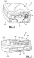
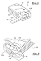
- la figure 9 est une vue partielle en perspective, en partie éclatée, d'une clé selon un second mode de réalisation de l'invention ;
- les figures 10 à 13 sont des vues en perspective de la clé représentée sur la figure 9 avec des coupes suivant divers plans sensiblement parallèles à l'axe de pivotement du panneton.
Claims (13)
- Clé du type comprenant:caractérisée en ce que les moyens de retenue comprennent un levier de commande (40) monté mobile autour d'un axe d'articulation (Y) lié au corps (22) entre une position de repos permettant la retenue du panneton (24) en position de rangement et une position de libération de ce panneton (24).un corps (22),un panneton (24) monté mobile autour d'un axe de pivotement (X) lié au corps (22) entre une position de rangement et une position d'utilisation vers laquelle il est rappelé élastiquement, etdes moyens libérables (40) de retenue du panneton (24) en position de rangement, portés par le corps (22),
- Clé selon la revendication 1, caractérisée en ce que l'axe (Y) d'articulation du levier de commande (40) est matérialisé par deux tourillons (46), solidaires du levier (40), emboítés dans deux glissières (48), formant flasques, ménagées dans le corps (22), ces glissières (48) s'étendant sensiblement parallèlement à une direction dite direction longitudinale des glissières.
- Clé selon la revendication 2, caractérisée en ce que chaque glissière (48) est délimitée par deux faces longitudinales opposées (F1, F2), chaque tourillon (46) ayant une section transversale polygonale délimitée par au moins deux paires de côtés consécutifs (C1, C2), les deux côtés (C1, C2) d'une paire formant respectivement deux butées de coopération avec une face longitudinale correspondante (F1, F2) de la glissière (48) pour définir les positions de repos et de libération du levier de commande (40).
- Clé selon la revendication 2 ou 3, caractérisée en ce qu'elle comprend des moyens (50, 52; 54, 56) d'immobilisation longitudinale des tourillons (46) dans les glissières (48) après emboítement de ces tourillons dans les glissières.
- Clé selon la revendication 4, caractérisée en ce que les moyens d'immobilisation longitudinale des tourillons comprennent des moyens complémentaires d'emboítement (50, 52), ménagés d'une part, sur un pivot (32), porté par le corps (22), matérialisant l'axe (X) de pivotement du panneton et, d'autre part, sur le levier de commande 40.
- Clé selon la revendication 5, caractérisée en ce que les moyens complémentaires d'emboítement (50, 52) forment une rotule.
- Clé selon la revendication 4, caractérisée en ce que les moyens d'immobilisation longitudinale des tourillons comprennent, d'une part, au moins une butée (54) de fin de course d'emboítement d'un tourillon (46) dans une glissière (48) correspondante et, d'autre part, un taquet (56) d'immobilisation de ce tourillon (46) contre la butée (54) de fin de course d'emboítement, les glissières (48) et le taquet (56) étant portés par deux parties (26A, 26B) assemblées lors du montage du corps (22).
- Clé selon l'une quelconque des revendications précédentes, caractérisée en ce que le corps (22) comprend un boítier (26) muni de première (26A) et seconde (26B) demi-coquilles, le levier de commande (40) étant articulé sur la première demi-coquille (26A).
- Clé selon les revendications 7 et 8 prises ensemble, caractérisée en ce que les glissières (48) sont ménagées sur la première demi-coquille (26A) et le taquet (56) est solidaire de la seconde demi-coquille (26B).
- Clé selon la revendication 8 ou 9, caractérisée en ce que la seconde demi-coquille (26B) porte des moyens (B1 à B3) de commande de moyens électroniques (28) logés dans le boítier (26).
- Clé selon l'une quelconque des revendications 8 à 10, caractérisée en ce que, en position de repos, le levier de commande (40) prolonge la seconde demi-coquille (26B).
- Clé selon l'une quelconque des revendications précédentes, caractérisée en ce que le levier de commande (40) est du premier genre, ce levier comportant une extrémité de manoeuvre (40A) et une extrémité (40B) de coopération avec le panneton entre lesquelles est intercalé l'axe (Y) d'articulation de ce levier.
- Clé selon l'une quelconque des revendications précédentes, caractérisée en ce que le levier de commande (40) est rappelé élastiquement en position de repos.
Applications Claiming Priority (2)
| Application Number | Priority Date | Filing Date | Title |
|---|---|---|---|
| FR0110607 | 2001-08-08 | ||
| FR0110607A FR2828516B1 (fr) | 2001-08-08 | 2001-08-08 | Cle perfectionnee a panneton articule |
Publications (2)
| Publication Number | Publication Date |
|---|---|
| EP1283316A1 true EP1283316A1 (fr) | 2003-02-12 |
| EP1283316B1 EP1283316B1 (fr) | 2006-06-21 |
Family
ID=8866388
Family Applications (1)
| Application Number | Title | Priority Date | Filing Date |
|---|---|---|---|
| EP20020017467 Expired - Lifetime EP1283316B1 (fr) | 2001-08-08 | 2002-08-05 | Clé perfectionnée à panneton articulé |
Country Status (4)
| Country | Link |
|---|---|
| EP (1) | EP1283316B1 (fr) |
| DE (1) | DE60212521T2 (fr) |
| ES (1) | ES2266364T3 (fr) |
| FR (1) | FR2828516B1 (fr) |
Cited By (3)
| Publication number | Priority date | Publication date | Assignee | Title |
|---|---|---|---|---|
| EP1561886A1 (fr) * | 2004-02-09 | 2005-08-10 | Alps Electric Co., Ltd. | Dispositif de commande à distance |
| FR2961242A1 (fr) * | 2010-06-14 | 2011-12-16 | Valeo Securite Habitacle | Dispositif de commande a cle escamotable notamment pour vehicule |
| JP2017008572A (ja) * | 2015-06-22 | 2017-01-12 | 三菱電機株式会社 | 電子キー装置 |
Citations (4)
| Publication number | Priority date | Publication date | Assignee | Title |
|---|---|---|---|---|
| FR2640670A1 (fr) * | 1988-12-20 | 1990-06-22 | Daimler Benz Ag | Porte-cle comportant une cle plate pivotante |
| DE19605353A1 (de) * | 1996-02-14 | 1997-08-21 | Valeo Sistemas De Seguridad S | Vorrichtung zur Montage eines elektronischen Bauteils in einen Schlüsselgriff |
| WO2001038673A1 (fr) * | 1999-11-24 | 2001-05-31 | Huf Hülsbeck & Fürst Gmbh & Co. Kg | Cle, en particulier pour automobiles |
| US20010002544A1 (en) * | 1999-12-07 | 2001-06-07 | Dittmar Schwab | Flat key |
-
2001
- 2001-08-08 FR FR0110607A patent/FR2828516B1/fr not_active Expired - Fee Related
-
2002
- 2002-08-05 DE DE2002612521 patent/DE60212521T2/de not_active Expired - Lifetime
- 2002-08-05 EP EP20020017467 patent/EP1283316B1/fr not_active Expired - Lifetime
- 2002-08-05 ES ES02017467T patent/ES2266364T3/es not_active Expired - Lifetime
Patent Citations (4)
| Publication number | Priority date | Publication date | Assignee | Title |
|---|---|---|---|---|
| FR2640670A1 (fr) * | 1988-12-20 | 1990-06-22 | Daimler Benz Ag | Porte-cle comportant une cle plate pivotante |
| DE19605353A1 (de) * | 1996-02-14 | 1997-08-21 | Valeo Sistemas De Seguridad S | Vorrichtung zur Montage eines elektronischen Bauteils in einen Schlüsselgriff |
| WO2001038673A1 (fr) * | 1999-11-24 | 2001-05-31 | Huf Hülsbeck & Fürst Gmbh & Co. Kg | Cle, en particulier pour automobiles |
| US20010002544A1 (en) * | 1999-12-07 | 2001-06-07 | Dittmar Schwab | Flat key |
Cited By (3)
| Publication number | Priority date | Publication date | Assignee | Title |
|---|---|---|---|---|
| EP1561886A1 (fr) * | 2004-02-09 | 2005-08-10 | Alps Electric Co., Ltd. | Dispositif de commande à distance |
| FR2961242A1 (fr) * | 2010-06-14 | 2011-12-16 | Valeo Securite Habitacle | Dispositif de commande a cle escamotable notamment pour vehicule |
| JP2017008572A (ja) * | 2015-06-22 | 2017-01-12 | 三菱電機株式会社 | 電子キー装置 |
Also Published As
| Publication number | Publication date |
|---|---|
| ES2266364T3 (es) | 2007-03-01 |
| DE60212521T2 (de) | 2007-07-05 |
| EP1283316B1 (fr) | 2006-06-21 |
| FR2828516A1 (fr) | 2003-02-14 |
| FR2828516B1 (fr) | 2004-06-18 |
| DE60212521D1 (de) | 2006-08-03 |
Similar Documents
| Publication | Publication Date | Title |
|---|---|---|
| EP2024219B1 (fr) | Systeme de verrouillage d'un premier arbre par rapport a un deuxieme arbre supprimant les jeux entre lesdits arbres | |
| EP1207255B1 (fr) | Module mécanique pour clé, clé munie de ce module et procédés de montage de ce module et de cette clé | |
| FR2809684A1 (fr) | Accoudoir escamotable | |
| FR2953489A1 (fr) | Systeme de fixation d'un siege notamment d'aeronef et siege comportant au moins un tel systeme. | |
| FR2817897A1 (fr) | Ensemble de fermeture d'une enceinte de rangement dans un habitacle de vehicule automobile | |
| EP1391361B1 (fr) | Agencement pour l'accouplement d'une tige de commande d'un servomoteur | |
| EP1283316B1 (fr) | Clé perfectionnée à panneton articulé | |
| EP1283315B1 (fr) | Clé à panneton articulé | |
| EP1247710A1 (fr) | Ensemble de pédale de frein pour un véhicule automobile | |
| EP2455142A1 (fr) | Dispositif de retenue qui comprend un mécanisme de verrouillage réversible d'un élément d'ancrage d'une chaussure | |
| EP0742329B1 (fr) | Dispositif de verrouillage d'un ouvrant de véhicule automobile comportant des moyens perfectionnés de montage d'un capuchon d'habillage | |
| FR2570659A1 (fr) | Retroviseur exterieur commandable a distance pour vehicules notamment pour vehicules automobiles | |
| FR2752779A1 (fr) | Dispositif perfectionne de commande d'une boite de vitesses pour vehicule automobile | |
| EP0628455A1 (fr) | Antivol de direction pour véhicule automobile | |
| EP4177497A1 (fr) | Mécanisme de blocage | |
| EP1605123B1 (fr) | Mécanisme d'ouverture/fermeture de portière de véhicule automobile | |
| EP1669269A1 (fr) | Liaison autobloquante entre une tige de commande à rotule et une pièce plane | |
| FR3107295A1 (fr) | Dispositif de verrouillage pour une pièce mobile d’un véhicule | |
| FR2598127A1 (fr) | Dispositif de reglage de l'orientation du reflecteur d'un projecteur de vehicule automobile | |
| EP3599146B1 (fr) | Crochet de connexion pour becquet | |
| FR3122684A1 (fr) | Dispositif de verrouillage pour une pièce mobile d’un véhicule | |
| EP0921040B1 (fr) | Système de cache d'une ouverture donnant accès à la fixation pour une barre de toit de véhicule | |
| FR2827832A1 (fr) | Ancre de type charrue | |
| FR2502080A1 (fr) | Perfectionnement aux retroviseurs pour vehicules | |
| EP0688925A1 (fr) | Verrou rotatif comportant des moyens perfectionnés d'assemblage |
Legal Events
| Date | Code | Title | Description |
|---|---|---|---|
| PUAI | Public reference made under article 153(3) epc to a published international application that has entered the european phase |
Free format text: ORIGINAL CODE: 0009012 |
|
| AK | Designated contracting states |
Designated state(s): AT BE BG CH CY CZ DE DK EE ES FI FR GB GR IE IT LI LU MC NL PT SE SK TR |
|
| AX | Request for extension of the european patent |
Extension state: AL LT LV MK RO SI |
|
| 17P | Request for examination filed |
Effective date: 20030812 |
|
| AKX | Designation fees paid |
Designated state(s): DE ES FR GB IT |
|
| RAP1 | Party data changed (applicant data changed or rights of an application transferred) |
Owner name: VALEO SECURITE HABITACLE S.A.S. |
|
| 17Q | First examination report despatched |
Effective date: 20040317 |
|
| GRAP | Despatch of communication of intention to grant a patent |
Free format text: ORIGINAL CODE: EPIDOSNIGR1 |
|
| GRAS | Grant fee paid |
Free format text: ORIGINAL CODE: EPIDOSNIGR3 |
|
| GRAA | (expected) grant |
Free format text: ORIGINAL CODE: 0009210 |
|
| AK | Designated contracting states |
Kind code of ref document: B1 Designated state(s): DE ES FR GB IT |
|
| REG | Reference to a national code |
Ref country code: GB Ref legal event code: FG4D Free format text: NOT ENGLISH |
|
| REF | Corresponds to: |
Ref document number: 60212521 Country of ref document: DE Date of ref document: 20060803 Kind code of ref document: P |
|
| GBT | Gb: translation of ep patent filed (gb section 77(6)(a)/1977) |
Effective date: 20060913 |
|
| REG | Reference to a national code |
Ref country code: ES Ref legal event code: FG2A Ref document number: 2266364 Country of ref document: ES Kind code of ref document: T3 |
|
| PLBE | No opposition filed within time limit |
Free format text: ORIGINAL CODE: 0009261 |
|
| STAA | Information on the status of an ep patent application or granted ep patent |
Free format text: STATUS: NO OPPOSITION FILED WITHIN TIME LIMIT |
|
| 26N | No opposition filed |
Effective date: 20070322 |
|
| REG | Reference to a national code |
Ref country code: FR Ref legal event code: CD Owner name: U-SHIN FRANCE SAS, FR Effective date: 20140901 Ref country code: FR Ref legal event code: TP Owner name: U-SHIN FRANCE SAS, FR Effective date: 20140901 |
|
| REG | Reference to a national code |
Ref country code: DE Ref legal event code: R082 Ref document number: 60212521 Country of ref document: DE Representative=s name: PRINZ & PARTNER MBB PATENTANWAELTE RECHTSANWAE, DE |
|
| REG | Reference to a national code |
Ref country code: DE Ref legal event code: R082 Ref document number: 60212521 Country of ref document: DE Representative=s name: PRINZ & PARTNER MBB PATENTANWAELTE RECHTSANWAE, DE Effective date: 20150515 Ref country code: DE Ref legal event code: R081 Ref document number: 60212521 Country of ref document: DE Owner name: U-SHIN FRANCE SAS, FR Free format text: FORMER OWNER: VALEO SECURITE HABITACLE S.A.S., CRETEIL, FR Effective date: 20150515 |
|
| REG | Reference to a national code |
Ref country code: ES Ref legal event code: PC2A Owner name: U-SHIN FRANCE SAS Effective date: 20160428 |
|
| REG | Reference to a national code |
Ref country code: FR Ref legal event code: PLFP Year of fee payment: 15 |
|
| PGFP | Annual fee paid to national office [announced via postgrant information from national office to epo] |
Ref country code: IT Payment date: 20160818 Year of fee payment: 15 Ref country code: DE Payment date: 20160817 Year of fee payment: 15 Ref country code: GB Payment date: 20160823 Year of fee payment: 15 |
|
| PGFP | Annual fee paid to national office [announced via postgrant information from national office to epo] |
Ref country code: FR Payment date: 20160831 Year of fee payment: 15 |
|
| PGFP | Annual fee paid to national office [announced via postgrant information from national office to epo] |
Ref country code: ES Payment date: 20160830 Year of fee payment: 15 |
|
| REG | Reference to a national code |
Ref country code: DE Ref legal event code: R119 Ref document number: 60212521 Country of ref document: DE |
|
| GBPC | Gb: european patent ceased through non-payment of renewal fee |
Effective date: 20170805 |
|
| REG | Reference to a national code |
Ref country code: FR Ref legal event code: ST Effective date: 20180430 |
|
| PG25 | Lapsed in a contracting state [announced via postgrant information from national office to epo] |
Ref country code: GB Free format text: LAPSE BECAUSE OF NON-PAYMENT OF DUE FEES Effective date: 20170805 Ref country code: DE Free format text: LAPSE BECAUSE OF NON-PAYMENT OF DUE FEES Effective date: 20180301 |
|
| PG25 | Lapsed in a contracting state [announced via postgrant information from national office to epo] |
Ref country code: IT Free format text: LAPSE BECAUSE OF NON-PAYMENT OF DUE FEES Effective date: 20170805 Ref country code: FR Free format text: LAPSE BECAUSE OF NON-PAYMENT OF DUE FEES Effective date: 20170831 |
|
| REG | Reference to a national code |
Ref country code: ES Ref legal event code: FD2A Effective date: 20181029 |
|
| PG25 | Lapsed in a contracting state [announced via postgrant information from national office to epo] |
Ref country code: ES Free format text: LAPSE BECAUSE OF NON-PAYMENT OF DUE FEES Effective date: 20170806 |