EP1283148B1 - Robust determination of handwheel position - Google Patents
Robust determination of handwheel position Download PDFInfo
- Publication number
- EP1283148B1 EP1283148B1 EP02077918A EP02077918A EP1283148B1 EP 1283148 B1 EP1283148 B1 EP 1283148B1 EP 02077918 A EP02077918 A EP 02077918A EP 02077918 A EP02077918 A EP 02077918A EP 1283148 B1 EP1283148 B1 EP 1283148B1
- Authority
- EP
- European Patent Office
- Prior art keywords
- hand
- function
- wheel position
- wheel
- signal
- Prior art date
- Legal status (The legal status is an assumption and is not a legal conclusion. Google has not performed a legal analysis and makes no representation as to the accuracy of the status listed.)
- Expired - Fee Related
Links
Images


Classifications
-
- B—PERFORMING OPERATIONS; TRANSPORTING
- B62—LAND VEHICLES FOR TRAVELLING OTHERWISE THAN ON RAILS
- B62D—MOTOR VEHICLES; TRAILERS
- B62D15/00—Steering not otherwise provided for
- B62D15/02—Steering position indicators ; Steering position determination; Steering aids
- B62D15/021—Determination of steering angle
- B62D15/0235—Determination of steering angle by measuring or deriving directly at the electric power steering motor
Definitions
- EPS Electric Power Steering
- This position may be used, for example, to cause the hand-wheel to return to center following a steering input.
- the return to center effect simulates the self-aligning torque due to positive caster of a conventional manual steering system, and causes the vehicle to be more comfortably controlled by a driver.
- absolute hand-wheel position information may be used.
- the absolute hand-wheel position is derived using a dual triangular wave (“DTW”) sensor to provide two position signals from which the relative position within 360 hand-wheel degrees is obtained.
- DTW dual triangular wave
- This information is then used by typically complex algorithms to determine the absolute hand-wheel position.
- a function of the algorithms is to provide the revolution offset or the "turn" at which the hand-wheel is currently positioned.
- typical algorithms may make use of torque signals and relative position signals to estimate the driving conditions and vehicle dynamics, require the hand-wheel to have moved through a certain travel to produce a travel exclusion signal, and/or use a previous position signal that is retrieved from a microprocessor memory.
- US-A-5465210 describes a system in accordance with the preamble of claim 1.
- an absolute hand-wheel position tracking system for an electric power steering system having a hand-wheel, an assist motor for providing an assist torque disposed relative to the hand-wheel, and a motor position sensor responsive to the assist motor, includes a hand-wheel position initialization function responsive to the hand-wheel; a motor position correction and scaling function responsive to the motor position sensor and responsive to the assist torque; an enable function responsive to the assist torque and responsive to the hand-wheel position initialization function; and an absolute hand-wheel position generation function in signal communication with the hand-wheel position initialization function, the motor position correction and scaling function, and the enable function.
- An absolute hand-wheel position tracking system for an electric power steering (“EPS") system makes the process of hand-wheel position tracking highly robust to hand-wheel position sensor failures and less complex in terms of software overhead.
- the method and apparatus of the tracking system may be substituted for direct absolute hand-wheel position sensing in many applications.
- the new method uses hand-wheel position information to calibrate or initialize motor position information, and thereafter uses the corresponding motor position signal as the source of the primary position information.
- Motor position information is already available within many EPS systems that use such sensor signals for motor commutation.
- reference numeral 70 generally designates an EPS system for a motor vehicle.
- a steering mechanism 72 is a rack-and-pinion type mechanism that includes a toothed rack (not shown) and a pinion gear (also not shown) located under a gear housing 74.
- a steering wheel 76 is coupled to an upper steering shaft 78. As the steering wheel 76 is turned, the upper steering shaft 78, which is connected to a lower steering shaft 80 through a universal joint 82, turns the pinion gear. Rotation of the pinion gear moves the toothed rack, which moves tie rods 84 (only one shown) that, in turn, move steering knuckles 86 (only one shown), which turn wheels 88 (only one shown).
- EPS assist torque is provided through an assist unit generally designated by reference numeral 90, which includes a controller 92 and an electric motor 94.
- a motor position commutation sensor 95 measures the relative position of the motor 94.
- the controller 92 is powered by a vehicle power supply 96 through a supply line 98.
- the controller 92 receives a signal indicative of the vehicle velocity on signal line 100.
- Initial hand-wheel position is measured by hand-wheel position sensor 102 and fed to the controller 92 through line 104.
- Position sensor 102 may be an optical-encoding type of sensor, a variable resistance type of sensor, or any other suitable type of position sensor for performing the functions of the hand-wheel position sensor 102.
- the torque sensor 103 senses the torque applied to the steering wheel 76 by a vehicle operator.
- the torque sensor 103 may include a torsion bar (not shown) and a variable-resistance type of sensor (also not shown) that outputs a variable resistance signal to the controller 92 through a line 106 in relation to the amount of twist on the torsion bar.
- Other suitable torque-sensing devices used with known signal processing techniques will suffice in alternate embodiments.
- the controller 92 In response to the inputs on lines 100, 104 and 106, the controller 92 sends a command signal through line 108 to the electric motor 94.
- the motor 94 supplies torque-assist to the steering system through a worm 107 and a worm gear 109, in order to provide a steering torque assist to the vehicle steering system in addition to a steering force exerted by the vehicle operator.
- the controller 92 of FIG. 1 includes a hand-wheel position initialization function having a state diagram generally designated by the reference numeral 60, including an initialize state 62 and an operate state 66.
- the hand-wheel position initialization function determines the validity of hand-wheel position sensor signals in order to calculate the measured hand-wheel position by taking multiple sensor readings over a period of time to determine the validity of the received sensor signals.
- the position initialization function determines that the signals are invalid for a given period of time, as described below with respect to FIG 3 , it produces a signal indicative of a failed initialization and the hand-wheel position initialization function enters a failed initialization state 64. If the current state of the hand-wheel position initialization function is the initialize state 62 or the failed initialization ("Failed Init") state 64, and the position function determines that the signals are valid for a given period of time, then the hand-wheel position initialization function returns a signal indicative of a successful initialization, and the hand-wheel position initialization function enters operate state 66.
- the hand-wheel position initialization function calculates a measured hand-wheel position with a calculation function (described below) until operation is disabled and the hand-wheel position initialization function enters a disable operation state 68 where the measured hand-wheel position is not used.
- the software determines if the hand-wheel position signals are valid in order to allow calculation of an absolute hand-wheel position, initialize system timers, and monitor validity inputs for the timer duration to accordingly update the state-transition vector and execute state function logic (described below with reference to FIG. 3 ) to set the outputs.
- the hand-wheel position initialization function operates in the FAILED INIT state 64 if it failed to determine that the hand-wheel position signals were valid on initialization.
- the appropriate fault flags are set and the software executes timer functions and monitors validity inputs to accordingly update the transition vector and execute state function logic to set the outputs once the initialization is successful.
- the hand-wheel position initialization function operates in the OPERATE state 66 to compute the hand-wheel position as described below.
- the hand-wheel position initialization function continues to monitor the validity inputs to accordingly update the state-transition vector and execute state function logic to set the outputs.
- the hand-wheel position initialization function will enter the disable operation state 68 when a signal becomes invalid and start checking timers.
- a hand-wheel position state logic function is indicated generally by the reference numeral 270.
- a state logic unit 272 receives a signal indicative of a valid hand-wheel sensor signal, a signal indicative of a short-duration timer value from a short-duration timer 274, and a signal indicative of a long-duration timer value from a long-duration timer 276.
- the state function 270 produces outputs including an initialize integrator flag, a valid hand-wheel position initialization flag, a hand-wheel position fault flag, a short-duration timer reset value for the short-duration timer 274, and a long-duration timer reset value for the long-duration timer 276.
- the valid hand-wheel position initialization flag is TRUE if all status check signals are true, and FALSE if any status check signal is false.
- the short-duration timer is used to verify the signal status. The timer is reset when the current value of the valid hand-wheel position flag does not equal the previous value. The short-duration timer is incremented and limited to a first calibratable threshold. The timer status is used to generate the "T" input to the state logic unit 272. If the timer value is greater than or equal to the first calibratable threshold, "T" is TRUE and the timer is limited to the threshold. If the timer is less than the first calibratable threshold, "T” is FALSE and the timer continues to operate.
- the long-duration timer is used to verify the signal status for a longer time duration than the short-duration timer.
- the long-duration timer is also reset when the current value of the valid hand-wheel position initialization flag does not equal the previous value.
- the timer is incremented and limited to a second calibratable threshold.
- the timer status is used to generate the "L" input. If the timer value is greater than or equal to the second calibratable threshold, "L" is TRUE and the timer is limited to the threshold. If the timer is less than the second calibratable threshold , "L” is FALSE and the timer continues to operate.
- the hand-wheel position fault flag "F” is used to indicate a fault.
- F is the hand-wheel position fault output for the hand-wheel position function 12 of FIG. 4 , described below.
- F is TRUE to indicate that a fault exists and
- F is FALSE to indicate that no hand-wheel position fault exists.
- F is initialized to FALSE.
- the valid hand-wheel position initialization flag "I” is TRUE once the hand-wheel position function has been initialized correctly.
- "I” is the valid initialization flag for the hand-wheel position function 12 of FIG. 4 .
- "I” is TRUE to indicate that the function initialized correctly, and FALSE to indicate that the function has not initialized correctly.
- FALSE FALSE.
- the initialize integrator state flag "S" is TRUE to indicate that the software has transitioned from either the INITIALIZE or the FAILED INIT state to the OPERATE state. At start-up, "S" is initialized to FALSE. This flag is used for initializing the state variable of the Offset Error Integrator function, described below.
- the T and L timers are only used by the state logic unit 272.
- reference numeral 10 generally designates an absolute hand-wheel position tracking system of the controller 92 of FIG. 1 .
- a hand-wheel position and initialization function block 12 receives signals indicative of the measured hand-wheel position from a sensor or predictive estimator, such as, for example, a dual triangular wave (“DTW”) sensor (not shown), and directly determines the measured hand-wheel position.
- a sensor or predictive estimator such as, for example, a dual triangular wave (“DTW”) sensor (not shown
- the hand-wheel position initialization function block 12 also produces a binary signal indicative of a valid absolute hand-wheel position initialization, as well as a binary signal indicative of any hand-wheel position faults.
- the binary signals and a signal indicative of an assist torque are received by an enable function block 14, which produces a binary enable signal if there has been a valid initialization, there are no present hand-wheel position faults and the assist torque is less than a threshold torque to account for excessive wind-up.
- a motor position correction and scaling function block 16 receives a signal indicative of motor position from the motor position sensor 95 of FIG. 1 and the signal indicative of assist torque from one of the torque sensor 103 of FIG. 1 or from the assist torque command signal, scales the signal indicative of motor position by a constant value, corrects for compliance error due to assist torque , and feeds the signal indicative of a scaled and corrected motor position to an absolute hand-wheel position generation function block 18.
- the absolute hand-wheel position generation function block 18 also receives a signal indicative of measured hand-wheel position from the hand-wheel position initialization function block 12, and receives the binary enable signal from the enable function block 14.
- the absolute hand-wheel position generation function block 18 produces a signal indicative of the absolute hand-wheel position.
- the inputs of the absolute hand-wheel position tracking system 10 are assist torque, hand-wheel position sensor and motor position signals, and the output is an absolute hand-wheel position signal.
- Measured hand-wheel position is used to initialize the motor position, which is used, in turn, to provide the output absolute hand-wheel position signal whether or not the current measured hand-wheel position signal is valid.
- the motor position has a small compliance with respect to the output shaft due to the motor coupling.
- the absolute hand-wheel position tracking system 10 compensates for this compliance to increase the accuracy of the absolute position signal.
- an alternate embodiment absolute hand-wheel position tracking system is generally designated by the reference numeral 110.
- the absolute hand-wheel position tracking system 110 is similar to the absolute hand-wheel position tracking system 10. Accordingly, like reference numerals preceded by the digit "1" are used to reference like features.
- a hand-wheel position initialization function block 112 receives signals indicative of measured hand-wheel position, determines the validity of the position signal inputs for input to an enable function block 114, and outputs the initial measured hand-wheel position.
- the hand-wheel position initialization function block 112 also produces binary signals indicative of any hand-wheel position sensor faults, and a signal indicative of a valid initialization of the hand-wheel position initialization function 112.
- the validity signals and a signal indicative of the assist torque are received by the enable function block 114, which produces a binary enabling signal.
- a motor position correction and scaling function block 116 receives a signal indicative of assist torque at motor compliance compensation block 122, and computes a compliance error.
- a summing junction 124 receives a signal indicative of motor position from the motor position sensor 95 of FIG.
- the output of the summing junction 124 is received by a scaling function 126 that scales the signal by a constant value corresponding to a motor gear ratio, and feeds the signal indicative of a scaled and corrected motor position in hand-wheel units to an absolute hand-wheel position generation function block 118.
- the absolute hand-wheel position generation function block 118 receives the signal indicative of measured hand-wheel position from the hand-wheel position initialization function block 112 at an inverting input of summing junction 128, which feeds a signal indicative of a hand-wheel position offset error to an error integration function block 120.
- the error integration function block 120 is enabled according to the binary enabling signal received from the enable function block 114. When the error integration function block 120 receives a logically false binary enabling signal, it ceases to adjust the offset error but continues to output a signal indicative of the motor position zero by holding the last valid motor position zero.
- the motor position zero is held to the last value by disabling the integration of further corrections until the measured hand-wheel position signal again becomes valid.
- the signal indicative of the motor position zero is received at the inverting input of a summing junction 130, which receives at its non-inverting input the signal indicative of a scaled and corrected motor position from the scaling function 126, and produces a signal indicative of a calculated absolute hand-wheel position that is fed back to the non-inverting input of the summing junction 128.
- the signal indicative of calculated absolute hand-wheel position is received by a switch function block 132.
- the switch function block 132 also receives the signal indicative of a valid hand-wheel initialization from the hand-wheel position function block 112. When the signal indicative of a valid hand-wheel initialization is logically false, the switch function block 132 outputs a zero or null signal. When the signal indicative of a valid hand-wheel initialization is logically true, the switch function block 132 outputs the signal indicative of calculated absolute hand-wheel position received from the summing junction 130.
- the inputs of the absolute hand-wheel position tracking system 110 are signals indicative of measured hand-wheel position, motor position, and assist torque, and the primary output is a signal indicative of absolute hand-wheel position.
- Measured hand-wheel position is used to initialize the motor position, which is used, in turn, to provide the output absolute hand-wheel position signal.
- the motor position has a small compliance with respect to the output shaft due to the motor coupling.
- the absolute hand-wheel position tracking system 110 compensates for this compliance to increase the accuracy of the absolute hand-wheel position signal.
- FIG. 6 a portion of the error integration function 120 of FIG. 5 is shown in greater detail and indicated generally by the reference numeral 121.
- the portion of the error integration function 121 receives the hand-wheel position offset error signal at an error limit function block 160.
- An output of the error limit function 160 is input to a scaler 162.
- the scaled output of scaler 162 is input to a non-inverting input of a summing junction 164.
- An output of junction 164 indicative of an offset state, is input to a series divider 166.
- An output of the divider 166 which is indicative of zeroed motor position, is passed only if the enabling signal of function block 114 is logically true.
- the output of the summing junction 164 is a state variable indicative of the hand-wheel offset relative to the motor, which is fed back to a delay or integration element 168 having an output feeding back to a non-inverting input of the summing junction 164.
- the hand-wheel position initialization function blocks 12 of FIG 4 and 112 of FIG. 5 can be any function blocks that calculate initial hand-wheel position from a hand-wheel position sensor or comparable source.
- the hand-wheel position initialization function block 12 of FIG. 4 includes a relative hand-wheel position function block 33 that receives DTW sensor position signals P1 and P2, and produces a signal indicative of the relative hand-wheel position.
- a revolution offset index determination function block 34 receives a third signal indicative of the number of turns of the hand-wheel and produces a signal indicative of the revolution offset index.
- the signal indicative of the revolution offset index and the signal indicative of the relative hand-wheel position are received, in turn, as inputs to a hand-wheel position calculation function block 36, which outputs a signal indicative of hand-wheel position to a non-inverting input of a summing junction 38.
- An inverting input of the summing junction 38 receives a constant position zero calibration signal from a function block 40, and produces as output a signal indicative of the absolute hand-wheel position.
- the hand-wheel position initialization function block 12 of FIG. 4 makes use of the DTW sensor providing P1 and P2 signals, along with a third sensor signal P3 that gives the turn information of the hand-wheel.
- This signal steps, every 180 degrees, through the lock to lock travel of the hand-wheel, although other step increments, such as, for example, every 90 degrees may be used in alternate embodiments.
- the function block uses P1 and P2 to provide relative position within 360 hand-wheel degrees. This information is then used with the P3 signal to compute the absolute hand-wheel position that gives absolute hand-wheel position over the entire hand-wheel travel.
- the hand-wheel position initialization function block 112 of FIG. 5 includes a relative hand-wheel position function block 133 that receives the DTW sensor position signals P1 and P2, and produces a signal indicative of the relative hand-wheel position.
- An unadjusted position function 142 receives the relative hand-wheel position from the function block 133 and a signal indicative of motor position, and produces as output a signal indicative of an unadjusted hand-wheel position.
- a vehicle dynamics function 144 receives the signal indicative of unadjusted hand-wheel position from the function 142, a signal indicative of a torque assist command, a signal indicative of a torque applied to the hand-wheel by a driver, a signal indicative of a vehicular speed, and a signal indicative of an assist motor velocity; and produces a first signal indicative of a hand-wheel revolution or turn offset and a latching signal.
- a travel exclusion function 146 also receives the signal indicative of unadjusted hand-wheel position from the algoritm 142, and produces a set of currently possible hand-wheel revolution or turn offset signals.
- a stored absolute position is retrieved from a memory location 147, where it was placed during the last EPS system shutdown, and received by a store last position function 148.
- the algoritm 148 also receives the signal indicative of unadjusted hand-wheel position from the function 142, and produces a signal indicative of the validity of the stored position as well as a signal indicative of the actual revolution offset of the stored position.
- a decision making function 150 receives each of the signals indicative of unadjusted hand-wheel position from the function 142, hand-wheel revolution or turn offset and the latching signal from the function 144, set of currently possible hand-wheel revolution or turn offset signals from the function 146, and validity of the stored position as well as the actual revolution offset of the stored position from the function 148; and produces a signal indicative of a selected revolution offset and a signal indicative of a percentage of return motion towards the center of the travel of the hand-wheel.
- a slew ramp function block 152 receives the signal indicative of the percent of return motion and produces a signal of a percentage of return slew rate.
- a walking function block 154 receives the signal indicative of the selected revolution offset from the function 150 and the signal indicative of unadjusted hand-wheel position from the function 142, and produces a signal indicative of a return state (described above with reference to FIG. 2 ) and a signal indicative of a filtered revolution offset.
- a summing junction 156 receives at a non-inverting terminal the signal indicative of unadjusted hand-wheel position from the function 142, and receives at an inverting terminal the signal indicative of the filtered revolution offset from the walking function block 154; and produces a signal indicative of the absolute position of the hand-wheel.
- the motor position signal provides relative position over the entire rack travel.
- a zero offset error is calculated between the measured hand-wheel position and absolute position.
- the error is integrated to provide a motor position calibration or zero point that is subtracted from the motor position to provide the final output absolute hand-wheel position.
- the error integrator operates only under conditions that are determined by the enable function. Once the motor position zero point has been initialized, absolute position will continue to be updated using motor position, whether or not the error integrator is enabled.
- the valid status of the hand-wheel position signals and corresponding fault status are used as conditions to enable the Error integrator.
- the motor wind-up with respect to the hand-wheel which might yield an incorrect value of absolute position if the error was allowed to be integrated, is also used as an enabling condition for the Error Integrator.
- the method uses assist torque as an input to make a determination of the motor wind-up.
- the diagnostic strategy used checks whether hand-wheel position was calculated on initialization and then provides absolute position information for the duration of that ignition cycle. Thus, faults are logged if signals for hand-wheel position indicated in FIG. 7 and FIG. 8 are determined to be invalid on initialization. If invalid hand-wheel signals are detected during operation, the absolute position continues to be updated based on motor position signals and no critical faults become logged.
- An advantage of the absolute hand-wheel position tracking system is that valid initial measured hand-wheel position signals allow for an absolute hand-wheel position signal based on motor position to be provided for the duration of that ignition cycle.
- the unique approach of using the error integrator and motor position allows for invalid hand-wheel position signals during operation. It also achieves a reliable and robust indirect measurement of absolute hand-wheel position. This makes the function less dependent on the hand-wheel position signals after the function has initialized. If initialized correctly, column hand-wheel position faults need not be logged during operation which will reduce warranty costs. This allows for the use of hand-wheel position sensors that that need only provide valid measured hand-wheel position on initialization.
- embodiments of the absolute hand-wheel position tracking system include EPS systems providing a determination of hand-wheel position that is robust to sensor failures that may occur during operation, with the added advantage of low software overhead.
Description
- In an Electric Power Steering ("EPS") system, it may be desirable to provide the absolute hand-wheel position. This position may be used, for example, to cause the hand-wheel to return to center following a steering input. The return to center effect simulates the self-aligning torque due to positive caster of a conventional manual steering system, and causes the vehicle to be more comfortably controlled by a driver. To determine the center, absolute hand-wheel position information may be used. Typically, the absolute hand-wheel position is derived using a dual triangular wave ("DTW") sensor to provide two position signals from which the relative position within 360 hand-wheel degrees is obtained. This information is then used by typically complex algorithms to determine the absolute hand-wheel position. A function of the algorithms is to provide the revolution offset or the "turn" at which the hand-wheel is currently positioned.
- To perform this task, typical algorithms may make use of torque signals and relative position signals to estimate the driving conditions and vehicle dynamics, require the hand-wheel to have moved through a certain travel to produce a travel exclusion signal, and/or use a previous position signal that is retrieved from a microprocessor memory.
-
US-A-5465210 describes a system in accordance with the preamble ofclaim 1. - The above described and other features are exemplified by the following Figures and Description in which an absolute hand-wheel position tracking system for an electric power steering system having a hand-wheel, an assist motor for providing an assist torque disposed relative to the hand-wheel, and a motor position sensor responsive to the assist motor, includes a hand-wheel position initialization function responsive to the hand-wheel; a motor position correction and scaling function responsive to the motor position sensor and responsive to the assist torque; an enable function responsive to the assist torque and responsive to the hand-wheel position initialization function; and an absolute hand-wheel position generation function in signal communication with the hand-wheel position initialization function, the motor position correction and scaling function, and the enable function.
- Referring now to the Figures wherein like elements are numbered alike:
-
FIG. 1 is a schematic diagram of an electric power steering system having a controller; -
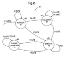
FIG. 2 is a state-transition diagram for a hand-wheel position initialization function of the controller ofFIG. 1 ; -
FIG. 3 is a schematic diagram of a hand-wheel position tracking state-transition function corresponding to the state-transition diagram ofFIG. 2 ; -
FIG. 4 is a schematic diagram for an absolute hand-wheel position tracking system portion of the controller ofFIG. 1 ; -
FIG. 5 is a schematic diagram for an alternate absolute hand-wheel position tracking system; -
FIG. 6 is an offset error integration function for an absolute hand-wheel position tracking system; -
FIG. 7 is a schematic diagram for a hand-wheel position initialization function for an absolute hand-wheel position tracking system; and -
FIG. 8 is a schematic diagram for an alternate hand-wheel position initialization function for an absolute hand-wheel position tracking system. - An absolute hand-wheel position tracking system for an electric power steering ("EPS") system makes the process of hand-wheel position tracking highly robust to hand-wheel position sensor failures and less complex in terms of software overhead. In addition, the method and apparatus of the tracking system may be substituted for direct absolute hand-wheel position sensing in many applications.
- The new method uses hand-wheel position information to calibrate or initialize motor position information, and thereafter uses the corresponding motor position signal as the source of the primary position information. Motor position information is already available within many EPS systems that use such sensor signals for motor commutation.
- Referring to
FIG. 1 ,reference numeral 70 generally designates an EPS system for a motor vehicle. Asteering mechanism 72 is a rack-and-pinion type mechanism that includes a toothed rack (not shown) and a pinion gear (also not shown) located under agear housing 74. Asteering wheel 76 is coupled to anupper steering shaft 78. As thesteering wheel 76 is turned, theupper steering shaft 78, which is connected to alower steering shaft 80 through auniversal joint 82, turns the pinion gear. Rotation of the pinion gear moves the toothed rack, which moves tie rods 84 (only one shown) that, in turn, move steering knuckles 86 (only one shown), which turn wheels 88 (only one shown). - EPS assist torque is provided through an assist unit generally designated by
reference numeral 90, which includes acontroller 92 and anelectric motor 94. A motorposition commutation sensor 95 measures the relative position of themotor 94. Thecontroller 92 is powered by avehicle power supply 96 through asupply line 98. Thecontroller 92 receives a signal indicative of the vehicle velocity onsignal line 100. Initial hand-wheel position is measured by hand-wheel position sensor 102 and fed to thecontroller 92 throughline 104.Position sensor 102 may be an optical-encoding type of sensor, a variable resistance type of sensor, or any other suitable type of position sensor for performing the functions of the hand-wheel position sensor 102. - As the
steering wheel 76 is turned, thetorque sensor 103 senses the torque applied to thesteering wheel 76 by a vehicle operator. Thetorque sensor 103 may include a torsion bar (not shown) and a variable-resistance type of sensor (also not shown) that outputs a variable resistance signal to thecontroller 92 through aline 106 in relation to the amount of twist on the torsion bar. Other suitable torque-sensing devices used with known signal processing techniques will suffice in alternate embodiments. - In response to the inputs on
lines controller 92 sends a command signal throughline 108 to theelectric motor 94. Themotor 94, in turn, supplies torque-assist to the steering system through aworm 107 and aworm gear 109, in order to provide a steering torque assist to the vehicle steering system in addition to a steering force exerted by the vehicle operator. - Turning now to
FIG. 2 , thecontroller 92 ofFIG. 1 includes a hand-wheel position initialization function having a state diagram generally designated by thereference numeral 60, including an initializestate 62 and an operatestate 66. In the initializestate 62, the hand-wheel position initialization function (described below) determines the validity of hand-wheel position sensor signals in order to calculate the measured hand-wheel position by taking multiple sensor readings over a period of time to determine the validity of the received sensor signals. - If the position initialization function determines that the signals are invalid for a given period of time, as described below with respect to
FIG 3 , it produces a signal indicative of a failed initialization and the hand-wheel position initialization function enters a failedinitialization state 64. If the current state of the hand-wheel position initialization function is the initializestate 62 or the failed initialization ("Failed Init")state 64, and the position function determines that the signals are valid for a given period of time, then the hand-wheel position initialization function returns a signal indicative of a successful initialization, and the hand-wheel position initialization function enters operatestate 66. In the operatestate 66, the hand-wheel position initialization function calculates a measured hand-wheel position with a calculation function (described below) until operation is disabled and the hand-wheel position initialization function enters adisable operation state 68 where the measured hand-wheel position is not used. - Thus, during operation in the initialize
state 62, the software determines if the hand-wheel position signals are valid in order to allow calculation of an absolute hand-wheel position, initialize system timers, and monitor validity inputs for the timer duration to accordingly update the state-transition vector and execute state function logic (described below with reference toFIG. 3 ) to set the outputs. - The hand-wheel position initialization function operates in the FAILED INIT
state 64 if it failed to determine that the hand-wheel position signals were valid on initialization. The appropriate fault flags are set and the software executes timer functions and monitors validity inputs to accordingly update the transition vector and execute state function logic to set the outputs once the initialization is successful. - The hand-wheel position initialization function operates in the OPERATE
state 66 to compute the hand-wheel position as described below. The hand-wheel position initialization function continues to monitor the validity inputs to accordingly update the state-transition vector and execute state function logic to set the outputs. The hand-wheel position initialization function will enter thedisable operation state 68 when a signal becomes invalid and start checking timers. - As shown in
FIG. 3 , a hand-wheel position state logic function is indicated generally by thereference numeral 270. Astate logic unit 272 receives a signal indicative of a valid hand-wheel sensor signal, a signal indicative of a short-duration timer value from a short-duration timer 274, and a signal indicative of a long-duration timer value from a long-duration timer 276. Thestate function 270 produces outputs including an initialize integrator flag, a valid hand-wheel position initialization flag, a hand-wheel position fault flag, a short-duration timer reset value for the short-duration timer 274, and a long-duration timer reset value for the long-duration timer 276. - In operation, the valid hand-wheel position initialization flag is TRUE if all status check signals are true, and FALSE if any status check signal is false. The short-duration timer is used to verify the signal status. The timer is reset when the current value of the valid hand-wheel position flag does not equal the previous value. The short-duration timer is incremented and limited to a first calibratable threshold. The timer status is used to generate the "T" input to the
state logic unit 272. If the timer value is greater than or equal to the first calibratable threshold, "T" is TRUE and the timer is limited to the threshold. If the timer is less than the first calibratable threshold, "T" is FALSE and the timer continues to operate. - The long-duration timer is used to verify the signal status for a longer time duration than the short-duration timer. The long-duration timer is also reset when the current value of the valid hand-wheel position initialization flag does not equal the previous value. The timer is incremented and limited to a second calibratable threshold. The timer status is used to generate the "L" input. If the timer value is greater than or equal to the second calibratable threshold, "L" is TRUE and the timer is limited to the threshold. If the timer is less than the second calibratable threshold , "L" is FALSE and the timer continues to operate.
- Thus, the shorter duration timer flag T is monitored to check for valid sensor signals, but if the sensor produces an invalid signal during this shorter period, the longer duration timer flag L is monitored to assure that the sensor signal remains valid for a longer period of time following the initial invalid signal. The hand-wheel position fault flag "F" is used to indicate a fault. "F" is the hand-wheel position fault output for the hand-
wheel position function 12 ofFIG. 4 , described below. "F" is TRUE to indicate that a fault exists and "F" is FALSE to indicate that no hand-wheel position fault exists. "F" is initialized to FALSE. - The valid hand-wheel position initialization flag "I" is TRUE once the hand-wheel position function has been initialized correctly. "I" is the valid initialization flag for the hand-
wheel position function 12 ofFIG. 4 . "I" is TRUE to indicate that the function initialized correctly, and FALSE to indicate that the function has not initialized correctly. At start-up, "I" is initialized to FALSE. - The initialize integrator state flag "S" is TRUE to indicate that the software has transitioned from either the INITIALIZE or the FAILED INIT state to the OPERATE state. At start-up, "S" is initialized to FALSE. This flag is used for initializing the state variable of the Offset Error Integrator function, described below. The T and L timers are only used by the
state logic unit 272. - Turning now to
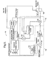
FIG. 4 ,reference numeral 10 generally designates an absolute hand-wheel position tracking system of thecontroller 92 ofFIG. 1 . A hand-wheel position andinitialization function block 12 receives signals indicative of the measured hand-wheel position from a sensor or predictive estimator, such as, for example, a dual triangular wave ("DTW") sensor (not shown), and directly determines the measured hand-wheel position. - The hand-wheel position
initialization function block 12 also produces a binary signal indicative of a valid absolute hand-wheel position initialization, as well as a binary signal indicative of any hand-wheel position faults. The binary signals and a signal indicative of an assist torque are received by anenable function block 14, which produces a binary enable signal if there has been a valid initialization, there are no present hand-wheel position faults and the assist torque is less than a threshold torque to account for excessive wind-up. - A motor position correction and scaling
function block 16 receives a signal indicative of motor position from themotor position sensor 95 ofFIG. 1 and the signal indicative of assist torque from one of thetorque sensor 103 ofFIG. 1 or from the assist torque command signal, scales the signal indicative of motor position by a constant value, corrects for compliance error due to assist torque , and feeds the signal indicative of a scaled and corrected motor position to an absolute hand-wheel positiongeneration function block 18. - The absolute hand-wheel position
generation function block 18 also receives a signal indicative of measured hand-wheel position from the hand-wheel positioninitialization function block 12, and receives the binary enable signal from theenable function block 14. The absolute hand-wheel positiongeneration function block 18 produces a signal indicative of the absolute hand-wheel position. - Thus, in operation, the inputs of the absolute hand-wheel
position tracking system 10 are assist torque, hand-wheel position sensor and motor position signals, and the output is an absolute hand-wheel position signal. Measured hand-wheel position is used to initialize the motor position, which is used, in turn, to provide the output absolute hand-wheel position signal whether or not the current measured hand-wheel position signal is valid. - When steering assist is provided, the motor position has a small compliance with respect to the output shaft due to the motor coupling. The absolute hand-wheel
position tracking system 10 compensates for this compliance to increase the accuracy of the absolute position signal. - Referring now to
FIG. 5 , an alternate embodiment absolute hand-wheel position tracking system is generally designated by thereference numeral 110. The absolute hand-wheelposition tracking system 110 is similar to the absolute hand-wheelposition tracking system 10. Accordingly, like reference numerals preceded by the digit "1" are used to reference like features. - A hand-wheel position
initialization function block 112 receives signals indicative of measured hand-wheel position, determines the validity of the position signal inputs for input to an enablefunction block 114, and outputs the initial measured hand-wheel position. The hand-wheel positioninitialization function block 112 also produces binary signals indicative of any hand-wheel position sensor faults, and a signal indicative of a valid initialization of the hand-wheelposition initialization function 112. The validity signals and a signal indicative of the assist torque are received by theenable function block 114, which produces a binary enabling signal. A motor position correction and scalingfunction block 116 receives a signal indicative of assist torque at motorcompliance compensation block 122, and computes a compliance error. A summingjunction 124 receives a signal indicative of motor position from themotor position sensor 95 ofFIG. 1 , and corrects the motor position signal for any computed compliance error by subtracting the compliance error received at its inverting input. The output of the summingjunction 124 is received by ascaling function 126 that scales the signal by a constant value corresponding to a motor gear ratio, and feeds the signal indicative of a scaled and corrected motor position in hand-wheel units to an absolute hand-wheel positiongeneration function block 118. - The absolute hand-wheel position
generation function block 118 receives the signal indicative of measured hand-wheel position from the hand-wheel positioninitialization function block 112 at an inverting input of summingjunction 128, which feeds a signal indicative of a hand-wheel position offset error to an errorintegration function block 120. The errorintegration function block 120 is enabled according to the binary enabling signal received from theenable function block 114. When the errorintegration function block 120 receives a logically false binary enabling signal, it ceases to adjust the offset error but continues to output a signal indicative of the motor position zero by holding the last valid motor position zero. - The motor position zero is held to the last value by disabling the integration of further corrections until the measured hand-wheel position signal again becomes valid. The signal indicative of the motor position zero is received at the inverting input of a summing
junction 130, which receives at its non-inverting input the signal indicative of a scaled and corrected motor position from thescaling function 126, and produces a signal indicative of a calculated absolute hand-wheel position that is fed back to the non-inverting input of the summingjunction 128. - The signal indicative of calculated absolute hand-wheel position is received by a
switch function block 132. Theswitch function block 132 also receives the signal indicative of a valid hand-wheel initialization from the hand-wheelposition function block 112. When the signal indicative of a valid hand-wheel initialization is logically false, theswitch function block 132 outputs a zero or null signal. When the signal indicative of a valid hand-wheel initialization is logically true, theswitch function block 132 outputs the signal indicative of calculated absolute hand-wheel position received from the summingjunction 130. - Thus, in operation, the inputs of the absolute hand-wheel
position tracking system 110 are signals indicative of measured hand-wheel position, motor position, and assist torque, and the primary output is a signal indicative of absolute hand-wheel position. Measured hand-wheel position is used to initialize the motor position, which is used, in turn, to provide the output absolute hand-wheel position signal. - When steering assist is provided, the motor position has a small compliance with respect to the output shaft due to the motor coupling. The absolute hand-wheel
position tracking system 110 compensates for this compliance to increase the accuracy of the absolute hand-wheel position signal. - Turning now to
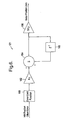
FIG. 6 , a portion of theerror integration function 120 ofFIG. 5 is shown in greater detail and indicated generally by thereference numeral 121. The portion of theerror integration function 121 receives the hand-wheel position offset error signal at an errorlimit function block 160. An output of theerror limit function 160 is input to ascaler 162. - The scaled output of
scaler 162 is input to a non-inverting input of a summingjunction 164. An output ofjunction 164, indicative of an offset state, is input to aseries divider 166. An output of thedivider 166, which is indicative of zeroed motor position, is passed only if the enabling signal offunction block 114 is logically true. The output of the summingjunction 164 is a state variable indicative of the hand-wheel offset relative to the motor, which is fed back to a delay orintegration element 168 having an output feeding back to a non-inverting input of the summingjunction 164. - As shown in
FIGs. 7 and8 , two exemplary configurations of the hand-wheel position calculation function are shown that may be used in the absolute hand-wheelposition tracking systems 10 ofFIG. 4 and 110 ofFIG. 5 , respectively. Thus, in alternate embodiments, the hand-wheel position initialization function blocks 12 ofFIG 4 and 112 ofFIG. 5 can be any function blocks that calculate initial hand-wheel position from a hand-wheel position sensor or comparable source. - In
FIG 7 , the hand-wheel positioninitialization function block 12 ofFIG. 4 includes a relative hand-wheelposition function block 33 that receives DTW sensor position signals P1 and P2, and produces a signal indicative of the relative hand-wheel position. A revolution offset indexdetermination function block 34 receives a third signal indicative of the number of turns of the hand-wheel and produces a signal indicative of the revolution offset index. The signal indicative of the revolution offset index and the signal indicative of the relative hand-wheel position are received, in turn, as inputs to a hand-wheel positioncalculation function block 36, which outputs a signal indicative of hand-wheel position to a non-inverting input of a summingjunction 38. An inverting input of the summingjunction 38 receives a constant position zero calibration signal from afunction block 40, and produces as output a signal indicative of the absolute hand-wheel position. - In operation, the hand-wheel position
initialization function block 12 ofFIG. 4 makes use of the DTW sensor providing P1 and P2 signals, along with a third sensor signal P3 that gives the turn information of the hand-wheel. This signal steps, every 180 degrees, through the lock to lock travel of the hand-wheel, although other step increments, such as, for example, every 90 degrees may be used in alternate embodiments. The function block uses P1 and P2 to provide relative position within 360 hand-wheel degrees. This information is then used with the P3 signal to compute the absolute hand-wheel position that gives absolute hand-wheel position over the entire hand-wheel travel. - Likewise, in
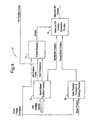
FIG. 8 , the hand-wheel positioninitialization function block 112 ofFIG. 5 includes a relative hand-wheel position function block 133 that receives the DTW sensor position signals P1 and P2, and produces a signal indicative of the relative hand-wheel position. Anunadjusted position function 142 receives the relative hand-wheel position from thefunction block 133 and a signal indicative of motor position, and produces as output a signal indicative of an unadjusted hand-wheel position. - A vehicle dynamics function 144 receives the signal indicative of unadjusted hand-wheel position from the
function 142, a signal indicative of a torque assist command, a signal indicative of a torque applied to the hand-wheel by a driver, a signal indicative of a vehicular speed, and a signal indicative of an assist motor velocity; and produces a first signal indicative of a hand-wheel revolution or turn offset and a latching signal. Atravel exclusion function 146 also receives the signal indicative of unadjusted hand-wheel position from thealgoritm 142, and produces a set of currently possible hand-wheel revolution or turn offset signals. A stored absolute position is retrieved from amemory location 147, where it was placed during the last EPS system shutdown, and received by a storelast position function 148. Thealgoritm 148 also receives the signal indicative of unadjusted hand-wheel position from thefunction 142, and produces a signal indicative of the validity of the stored position as well as a signal indicative of the actual revolution offset of the stored position. - A
decision making function 150 receives each of the signals indicative of unadjusted hand-wheel position from thefunction 142, hand-wheel revolution or turn offset and the latching signal from thefunction 144, set of currently possible hand-wheel revolution or turn offset signals from thefunction 146, and validity of the stored position as well as the actual revolution offset of the stored position from thefunction 148; and produces a signal indicative of a selected revolution offset and a signal indicative of a percentage of return motion towards the center of the travel of the hand-wheel. A slewramp function block 152 receives the signal indicative of the percent of return motion and produces a signal of a percentage of return slew rate. - A
walking function block 154 receives the signal indicative of the selected revolution offset from thefunction 150 and the signal indicative of unadjusted hand-wheel position from thefunction 142, and produces a signal indicative of a return state (described above with reference toFIG. 2 ) and a signal indicative of a filtered revolution offset. A summingjunction 156 receives at a non-inverting terminal the signal indicative of unadjusted hand-wheel position from thefunction 142, and receives at an inverting terminal the signal indicative of the filtered revolution offset from thewalking function block 154; and produces a signal indicative of the absolute position of the hand-wheel. - Thus, in operation of the absolute hand-wheel position tracking system, the motor position signal provides relative position over the entire rack travel. A zero offset error is calculated between the measured hand-wheel position and absolute position. The error is integrated to provide a motor position calibration or zero point that is subtracted from the motor position to provide the final output absolute hand-wheel position. The error integrator operates only under conditions that are determined by the enable function. Once the motor position zero point has been initialized, absolute position will continue to be updated using motor position, whether or not the error integrator is enabled.
- The valid status of the hand-wheel position signals and corresponding fault status are used as conditions to enable the Error integrator. In addition, the motor wind-up with respect to the hand-wheel, which might yield an incorrect value of absolute position if the error was allowed to be integrated, is also used as an enabling condition for the Error Integrator. The method uses assist torque as an input to make a determination of the motor wind-up.
- The diagnostic strategy used checks whether hand-wheel position was calculated on initialization and then provides absolute position information for the duration of that ignition cycle. Thus, faults are logged if signals for hand-wheel position indicated in
FIG. 7 andFIG. 8 are determined to be invalid on initialization. If invalid hand-wheel signals are detected during operation, the absolute position continues to be updated based on motor position signals and no critical faults become logged. - An advantage of the absolute hand-wheel position tracking system is that valid initial measured hand-wheel position signals allow for an absolute hand-wheel position signal based on motor position to be provided for the duration of that ignition cycle. The unique approach of using the error integrator and motor position allows for invalid hand-wheel position signals during operation. It also achieves a reliable and robust indirect measurement of absolute hand-wheel position. This makes the function less dependent on the hand-wheel position signals after the function has initialized. If initialized correctly, column hand-wheel position faults need not be logged during operation which will reduce warranty costs. This allows for the use of hand-wheel position sensors that that need only provide valid measured hand-wheel position on initialization.
- Accordingly, embodiments of the absolute hand-wheel position tracking system include EPS systems providing a determination of hand-wheel position that is robust to sensor failures that may occur during operation, with the added advantage of low software overhead.
- While the description has been made with reference to exemplary embodiments, it will be understood by those of ordinary skill in the pertinent art that various changes may be made and equivalents may be substituted for the elements thereof without departing from the scope of the claims. In addition, numerous modifications may be made to adapt the teachings of the disclosure to a particular object or situation without departing from the essential scope of the claims. Therefore, it is intended that the Claims not be limited to the particular embodiments disclosed as the currently preferred best modes contemplated for carrying out the teachings herein, but that the Claims shall cover all embodiments falling within the scope of the claims.
Claims (21)
- An absolute hand-wheel position tracking system (10, 110) comprising:means (16, 116, 95) for receiving a signal indicative of motor (94) position; characterised bymeans (12, 112) for initializing a signal indicative of hand-wheel (76) position;means (14, 114) for correcting said received signal in accordance with said initialized signal;means ( 16, 116) for scaling said corrected signal in accordance with a motor gear ratio; andmeans (18) for tracking an absolute hand-wheel position corresponding to said corrected and scaled motor position signal
- A tracking system as defined in Claim 1, further comprising:a hand-wheel position sensor (102) disposed relative to said hand-wheel (76) in signal communication with said hand-wheel position initialization function (12).
- A tracking system as defined in Claim 2, further comprising:an absolute hand-wheel position initialization function (112) in signal communication with said hand-wheel position sensor (102).
- A tracking system as defined in Claim 1, further comprising:a motor position scaler (119) in signal communication with a motor position sensor (95).
- A tracking system as defined in Claim 4, further comprising:a motor compliance compensation function (122) responsive to said assist torque.
- A tracking system as defined in Claim 1, further comprising:a torque sensor (103) in signal communication with said hand-wheel (76).
- A tracking system as defined in Claim 1, further comprising:an error integration function (120) in signal communication with said hand-wheel position initialization function (112) and said enable function (114).
- A tracking system as defined in Claim 1, further comprising:a relative hand-wheel position function (33, 133) responsive to said hand-wheel; andan absolute hand-wheel position initialization function (12, 112) in signal communication with said relative hand-wheel position function.
- A tracking system as defined in Claim 1, further comprising:an error integration function (120) in signal communication with said hand-wheel position initialization function (112); anda filtering function (154) in signal communication with said hand-wheel position generation function (118) to produce a signal indicative of an absolute hand-wheel position.
- A tracking system as defined in Claim 9, the filtering function (154) comprising:a switch box function (132) in signal communication with the hand-wheel position initialization function (112).
- A tracking system as defined in Claim 9, the filtering function (154) comprising:a walk function (154) in signal communication with the hand-wheel position generation function (118).
- A tracking system as defined in Claim 9, further comprising:a relative hand-wheel position function (33) responsive to the hand-wheel;a revolution offset index determination function (34) responsive to the hand-wheel (76);a hand-wheel position calculation function (36) in signal communication with said relative hand-wheel position function (33) and said revolution offset index determination function (34); anda zero position calibration function (40) in signal communication with said hand-wheel position calculation function (36) to produce a signal indicative of an initialized absolute hand-wheel position.
- A tracking system as defined in Claim 1, further comprising:an error limit function (160) in signal communication with said hand-wheel position initialization function (112); andan offset error integrating function (121) in signal communication with said error limit function (160) and said enabling function (114) to produce a correction to a signal indicative of a motor position.
- A tracking system as defined in Claim 1, further comprising:a relative hand-wheel position function (33) responsive to the hand-wheel (76);a revolution offset index determination function (34) responsive to the hand-wheel;a hand-wheel position calculation function (36) in signal communication with said relative hand-wheel position function (33) and said revolution offset index determination function (34); anda zero position calibration function (40) in signal communication with said hand-wheel position calculation function (36) to produce a signal indicative of an initial absolute hand-wheel position.
- A tracking system as defined in Claim 1, further comprising:a relative hand-wheel position function (33) responsive to the hand-wheel;an unadjusted position function (142) in signal communication with said relative hand-wheel position function (133);a vehicle dynamics function (144) in signal communication with said unadjusted position function (142);a travel exclusion function (146) in signal communication with said unadjusted position function (142);a store last position function (148) in signal communication with said unadjusted position function (142);a decision-making function (150) in signal communication with at least one of said vehicle dynamics function (144), said travel exclusion function (146), and said store last position function (148);a walk function (154) in signal communication with said decision-making function (150) and with said unadjusted position function (142); anda summing function (156) in signal communication with said walk function (154) and with said unadjusted position function (142) to produce a signal indicative of an absolute hand-wheel position.
- A tracking system as defined in Claim 15, further comprising a return state generator (154).
- A tracking system as defined in Claim 15, further comprising a slew ramp function (152) for producing a signal indicative of a slew rate.
- A tracking system as defined in Claim 15, further comprising a storage location (147) for maintaining a stored absolute position during a shutdown.
- A method for tracking the absolute hand-wheel position of an electric power steering system (70), the method comprising:initializing a signal indicative of hand-wheel position;receiving a signal indicative of motor position;correcting said received signal in accordance with said initialized signal;scaling said corrected signal in accordance with a motor gear ratio; andtracking an absolute hand-wheel position corresponding to said corrected and scaled motor position signal.
- A method as defined in Claim 19, further comprising:controlling an assist motor (94) in accordance with said tracked absolute hand-wheel position to provide a return-to-center assist torque (90).
- A method as defined in Claim 19, further comprising:measuring an initial hand-wheel position;enabling an integrating function (120) in correspondence with said measured hand-wheel position;sensing a motor position;integrating an offset to said sensed motor position to produce a signal indicative of a correction to a signal indicative of a hand-wheel position; andproducing a signal indicative of an absolute hand-wheel position in correspondence with the sensed motor position and the integrated offset.
Applications Claiming Priority (2)
| Application Number | Priority Date | Filing Date | Title |
|---|---|---|---|
| US927610 | 2001-08-10 | ||
| US09/927,610 US6535805B2 (en) | 2001-08-10 | 2001-08-10 | Robust determination of hand-wheel position |
Publications (3)
| Publication Number | Publication Date |
|---|---|
| EP1283148A2 EP1283148A2 (en) | 2003-02-12 |
| EP1283148A3 EP1283148A3 (en) | 2004-02-04 |
| EP1283148B1 true EP1283148B1 (en) | 2009-04-15 |
Family
ID=25454983
Family Applications (1)
| Application Number | Title | Priority Date | Filing Date |
|---|---|---|---|
| EP02077918A Expired - Fee Related EP1283148B1 (en) | 2001-08-10 | 2002-07-18 | Robust determination of handwheel position |
Country Status (4)
| Country | Link |
|---|---|
| US (1) | US6535805B2 (en) |
| EP (1) | EP1283148B1 (en) |
| JP (1) | JP2003081101A (en) |
| DE (1) | DE60231941D1 (en) |
Families Citing this family (17)
| Publication number | Priority date | Publication date | Assignee | Title |
|---|---|---|---|---|
| US7023224B2 (en) * | 2002-03-18 | 2006-04-04 | Delphi Technologies, Inc. | Low power absolute position sensor and method |
| JP3842235B2 (en) * | 2003-03-27 | 2006-11-08 | 株式会社ジェイテクト | Control parameter setting method, control parameter setting device, and electric power steering device |
| US20060293811A1 (en) * | 2005-06-24 | 2006-12-28 | Keith Andreasen | Automotive data logger |
| KR100764198B1 (en) * | 2006-01-12 | 2007-10-05 | 주식회사 만도 | Electric Power Steering Apparatus Equipped with Steering Angle Sensor |
| US7543679B2 (en) | 2006-07-28 | 2009-06-09 | Delphi Technologies, Inc. | Compensation of periodic sensor errors in electric power steering systems |
| EP1886899A1 (en) | 2006-08-10 | 2008-02-13 | Mando Corporation | Electric power steering apparatus equipped with a mechanism for adjusting the tension of a transmission belt |
| US7725227B2 (en) * | 2006-12-15 | 2010-05-25 | Gm Global Technology Operations, Inc. | Method, system, and apparatus for providing enhanced steering pull compensation |
| EP1992549B1 (en) * | 2007-05-18 | 2012-07-25 | GM Global Technology Operations LLC | Method for determining an absolute rotational position of a Vehicle Steering Column |
| JP4605265B2 (en) * | 2008-07-22 | 2011-01-05 | トヨタ自動車株式会社 | Vehicle steering device |
| US8638568B2 (en) | 2010-08-27 | 2014-01-28 | Steering Solutions Ip Holding Corporation | Mounted circuit card assembly |
| US9106175B2 (en) | 2010-11-23 | 2015-08-11 | Steering Solutions Ip Holding Corporation | Diagnostic system and method for an electric power steering system |
| CN103646591B (en) * | 2013-12-16 | 2016-02-10 | 北京经纬恒润科技有限公司 | A kind of sensor zero point learning method and system |
| US9555814B2 (en) * | 2014-09-29 | 2017-01-31 | Ford Global Technologies, Llc | Unexpected thermal event assist |
| EP3090921B1 (en) * | 2015-02-19 | 2018-12-05 | NSK Ltd. | Vehicle steering angle detection apparatus, and electric power steering apparatus equipped with same |
| KR102532320B1 (en) * | 2016-09-05 | 2023-05-16 | 현대자동차주식회사 | System and method for movable electric apparatus of vehicle |
| JP7110787B2 (en) * | 2018-07-23 | 2022-08-02 | 株式会社ジェイテクト | steering controller |
| US11411516B2 (en) * | 2020-03-04 | 2022-08-09 | Ford Global Technologies, Llc | Detection and control of electric machine with any combination of position sensor number of pole pairs and electric machine number of pole pairs |
Family Cites Families (16)
| Publication number | Priority date | Publication date | Assignee | Title |
|---|---|---|---|---|
| US4372407A (en) * | 1978-08-17 | 1983-02-08 | Owens-Illinois, Inc. | Independent steering and propulsion system for off road vehicle |
| US5465210A (en) * | 1994-08-18 | 1995-11-07 | General Motors Corporation | Method for determining a vehicle steering wheel center position |
| DE19508607C1 (en) * | 1995-03-10 | 1996-08-01 | Kostal Leopold Gmbh & Co Kg | Steering angle sensor for motor vehicle |
| US5668722A (en) | 1995-10-02 | 1997-09-16 | General Motors Corporation | Electric power steering control |
| US6053270A (en) * | 1995-11-02 | 2000-04-25 | Honda Giken Kogyo Kabushiki Kaisha | Steering angle correcting system in vehicle |
| US5948030A (en) | 1997-07-25 | 1999-09-07 | General Motors Corporation | Steering angle determaination method and apparatus |
| US6068078A (en) * | 1998-06-16 | 2000-05-30 | Trw Inc. | Electric steering system |
| US6050360A (en) * | 1998-06-24 | 2000-04-18 | General Motors Corporation | Apparatus and method for producing a desired return torque in a vehicle power steering system having a rotational steering position sensor |
| US6039144A (en) | 1998-06-24 | 2000-03-21 | General Motors Corporation | Apparatus and method for producing a desired return torque in a vehicle power steering system having a rotational steering position sensor |
| JP3497746B2 (en) * | 1998-10-26 | 2004-02-16 | 本田技研工業株式会社 | Electric power steering device |
| JP3712876B2 (en) * | 1998-12-01 | 2005-11-02 | 三菱電機株式会社 | Electric power steering control device |
| JP3694423B2 (en) * | 1999-06-25 | 2005-09-14 | 本田技研工業株式会社 | Vehicle and steering control device for vehicle |
| JP2001158372A (en) * | 1999-12-03 | 2001-06-12 | Honda Motor Co Ltd | Vehicle behavior control device |
| JP3968972B2 (en) * | 2000-08-14 | 2007-08-29 | 日本精工株式会社 | Control device for electric power steering device |
| US6408234B1 (en) * | 2000-09-07 | 2002-06-18 | Delphi Technologies, Inc. | Automatic compensation for electric power steering hysteresis |
| JP4419114B2 (en) * | 2000-11-14 | 2010-02-24 | 株式会社ジェイテクト | Vehicle steering system |
-
2001
- 2001-08-10 US US09/927,610 patent/US6535805B2/en not_active Expired - Fee Related
-
2002
- 2002-07-18 DE DE60231941T patent/DE60231941D1/en not_active Expired - Lifetime
- 2002-07-18 EP EP02077918A patent/EP1283148B1/en not_active Expired - Fee Related
- 2002-07-31 JP JP2002222802A patent/JP2003081101A/en active Pending
Also Published As
| Publication number | Publication date |
|---|---|
| DE60231941D1 (en) | 2009-05-28 |
| JP2003081101A (en) | 2003-03-19 |
| US20030033064A1 (en) | 2003-02-13 |
| EP1283148A3 (en) | 2004-02-04 |
| US6535805B2 (en) | 2003-03-18 |
| EP1283148A2 (en) | 2003-02-12 |
Similar Documents
| Publication | Publication Date | Title |
|---|---|---|
| EP1283148B1 (en) | Robust determination of handwheel position | |
| US8960363B2 (en) | Electric power steering device | |
| US5343393A (en) | Steering angle detecting apparatus for motor vehicles based on the phase difference between a steering angle detection signal and steering angle estimated signal | |
| EP2315690B1 (en) | Vehicular steering apparatus and control method thereof | |
| KR101628736B1 (en) | Apparatus for compensating zero point of steering angle sensor using rotational displacement difference and method thereof | |
| US6425454B1 (en) | Vehicle electric power assist steering system and method using velocity based torque estimation | |
| EP2492168B1 (en) | Electric power steering device for vehicle | |
| EP1932745B1 (en) | Method and apparatus for compensating steering pull | |
| US7711464B2 (en) | Steering system with lane keeping integration | |
| US5065325A (en) | Device for determining malfunctioning of electric-motor-assisted power steering system of motor vehicle | |
| US9266559B2 (en) | Electric power steering device | |
| US20050171667A1 (en) | Electric power steering system and method having abnormality compensation function | |
| US6729435B2 (en) | Apparatus and method for controlling electric power steering system | |
| EP1538065B1 (en) | Steering control apparatus with return torque control | |
| WO2017068895A1 (en) | Electric power steering device | |
| EP1944221A1 (en) | Controller of electric power steering system | |
| US6263270B1 (en) | Vehicle steering control apparatus | |
| US6439336B2 (en) | Electric power steering apparatus | |
| WO2013175729A1 (en) | Vehicle steering angle detection device and electric power steering device | |
| EP1882624B1 (en) | Compensation of periodic sensor errors in electric power steering systems | |
| US6661191B2 (en) | Method and apparatus for compensating drive current for an electric motor vehicle steering system | |
| JP2013241131A (en) | Vehicle steering angle detection device and electric power steering device | |
| KR102452643B1 (en) | Method for compensating offset of current sensor | |
| JP2817556B2 (en) | Abnormality detection device for electric motor in electric power steering system | |
| US20230314255A1 (en) | Torque sensor fault detection method |
Legal Events
| Date | Code | Title | Description |
|---|---|---|---|
| PUAI | Public reference made under article 153(3) epc to a published international application that has entered the european phase |
Free format text: ORIGINAL CODE: 0009012 |
|
| AK | Designated contracting states |
Designated state(s): AT BE BG CH CY CZ DE DK EE ES FI FR GB GR IE IT LI LU MC NL PT SE SK TR |
|
| AX | Request for extension of the european patent |
Extension state: AL LT LV MK RO SI |
|
| PUAL | Search report despatched |
Free format text: ORIGINAL CODE: 0009013 |
|
| AK | Designated contracting states |
Kind code of ref document: A3 Designated state(s): AT BE BG CH CY CZ DE DK EE ES FI FR GB GR IE IT LI LU MC NL PT SE SK TR |
|
| AX | Request for extension of the european patent |
Extension state: AL LT LV MK RO SI |
|
| RIC1 | Information provided on ipc code assigned before grant |
Ipc: 7B 62D 6/00 B Ipc: 7B 62D 5/04 B Ipc: 7B 62D 15/02 A |
|
| 17P | Request for examination filed |
Effective date: 20040804 |
|
| AKX | Designation fees paid |
Designated state(s): DE FR GB IT |
|
| 17Q | First examination report despatched |
Effective date: 20070111 |
|
| GRAP | Despatch of communication of intention to grant a patent |
Free format text: ORIGINAL CODE: EPIDOSNIGR1 |
|
| GRAS | Grant fee paid |
Free format text: ORIGINAL CODE: EPIDOSNIGR3 |
|
| GRAA | (expected) grant |
Free format text: ORIGINAL CODE: 0009210 |
|
| AK | Designated contracting states |
Kind code of ref document: B1 Designated state(s): DE FR GB IT |
|
| REG | Reference to a national code |
Ref country code: GB Ref legal event code: FG4D |
|
| REF | Corresponds to: |
Ref document number: 60231941 Country of ref document: DE Date of ref document: 20090528 Kind code of ref document: P |
|
| PLBE | No opposition filed within time limit |
Free format text: ORIGINAL CODE: 0009261 |
|
| STAA | Information on the status of an ep patent application or granted ep patent |
Free format text: STATUS: NO OPPOSITION FILED WITHIN TIME LIMIT |
|
| 26N | No opposition filed |
Effective date: 20100118 |
|
| REG | Reference to a national code |
Ref country code: FR Ref legal event code: TP |
|
| REG | Reference to a national code |
Ref country code: GB Ref legal event code: 732E Free format text: REGISTERED BETWEEN 20101028 AND 20101103 |
|
| PG25 | Lapsed in a contracting state [announced via postgrant information from national office to epo] |
Ref country code: IT Free format text: LAPSE BECAUSE OF FAILURE TO SUBMIT A TRANSLATION OF THE DESCRIPTION OR TO PAY THE FEE WITHIN THE PRESCRIBED TIME-LIMIT Effective date: 20090415 |
|
| REG | Reference to a national code |
Ref country code: DE Ref legal event code: R081 Ref document number: 60231941 Country of ref document: DE Owner name: GM GLOBAL TECHNOLOGY OPERATIONS LLC (N. D. GES, US Free format text: FORMER OWNER: DELPHI TECHNOLOGIES, INC., TROY, MICH., US Effective date: 20110412 Ref country code: DE Ref legal event code: R081 Ref document number: 60231941 Country of ref document: DE Owner name: STEERING SOLUTIONS IP HOLDING CORP., SAGINAW, US Free format text: FORMER OWNER: DELPHI TECHNOLOGIES, INC., TROY, MICH., US Effective date: 20110412 |
|
| REG | Reference to a national code |
Ref country code: DE Ref legal event code: R082 Ref document number: 60231941 Country of ref document: DE Representative=s name: MANITZ, FINSTERWALD & PARTNER GBR, DE |
|
| PGFP | Annual fee paid to national office [announced via postgrant information from national office to epo] |
Ref country code: GB Payment date: 20120725 Year of fee payment: 11 |
|
| REG | Reference to a national code |
Ref country code: DE Ref legal event code: R081 Ref document number: 60231941 Country of ref document: DE Owner name: GM GLOBAL TECHNOLOGY OPERATIONS LLC (N. D. GES, US Free format text: FORMER OWNER: GM GLOBAL TECHNOLOGY OPERATIONS, INC., DETROIT, US Effective date: 20121019 Ref country code: DE Ref legal event code: R081 Ref document number: 60231941 Country of ref document: DE Owner name: STEERING SOLUTIONS IP HOLDING CORP., US Free format text: FORMER OWNER: GM GLOBAL TECHNOLOGY OPERATIONS, INC., DETROIT, US Effective date: 20121019 Ref country code: DE Ref legal event code: R082 Ref document number: 60231941 Country of ref document: DE Representative=s name: MANITZ, FINSTERWALD & PARTNER GBR, DE Effective date: 20121019 Ref country code: DE Ref legal event code: R081 Ref document number: 60231941 Country of ref document: DE Owner name: GM GLOBAL TECHNOLOGY OPERATIONS LLC (N. D. GES, US Free format text: FORMER OWNER: GM GLOBAL TECHNOLOGY OPERATIONS, INC., DETROIT, MICH., US Effective date: 20121019 Ref country code: DE Ref legal event code: R081 Ref document number: 60231941 Country of ref document: DE Owner name: STEERING SOLUTIONS IP HOLDING CORP., SAGINAW, US Free format text: FORMER OWNER: GM GLOBAL TECHNOLOGY OPERATIONS, INC., DETROIT, MICH., US Effective date: 20121019 |
|
| REG | Reference to a national code |
Ref country code: DE Ref legal event code: R082 Ref document number: 60231941 Country of ref document: DE Representative=s name: MANITZ, FINSTERWALD & PARTNER GBR, DE |
|
| REG | Reference to a national code |
Ref country code: DE Ref legal event code: R081 Ref document number: 60231941 Country of ref document: DE Owner name: GM GLOBAL TECHNOLOGY OPERATIONS LLC (N. D. GES, US Free format text: FORMER OWNER: GM GLOBAL TECHNOLOGY OPERATIONS LLC (N. D. GES. D. STAATES DELAWARE), DETROIT, US Effective date: 20130313 Ref country code: DE Ref legal event code: R082 Ref document number: 60231941 Country of ref document: DE Representative=s name: MANITZ, FINSTERWALD & PARTNER GBR, DE Effective date: 20130313 Ref country code: DE Ref legal event code: R081 Ref document number: 60231941 Country of ref document: DE Owner name: STEERING SOLUTIONS IP HOLDING CORP., US Free format text: FORMER OWNER: GM GLOBAL TECHNOLOGY OPERATIONS LLC (N. D. GES. D. STAATES DELAWARE), DETROIT, US Effective date: 20130313 Ref country code: DE Ref legal event code: R081 Ref document number: 60231941 Country of ref document: DE Owner name: STEERING SOLUTIONS IP HOLDING CORP., SAGINAW, US Free format text: FORMER OWNER: GM GLOBAL TECHNOLOGY OPERATIONS LLC (N. D. GES. D. STAATES DELAWARE), DETROIT, MICH., US Effective date: 20130313 Ref country code: DE Ref legal event code: R081 Ref document number: 60231941 Country of ref document: DE Owner name: GM GLOBAL TECHNOLOGY OPERATIONS LLC (N. D. GES, US Free format text: FORMER OWNER: GM GLOBAL TECHNOLOGY OPERATIONS LLC (N. D. GES. D. STAATES DELAWARE), DETROIT, MICH., US Effective date: 20130313 |
|
| PGFP | Annual fee paid to national office [announced via postgrant information from national office to epo] |
Ref country code: DE Payment date: 20130729 Year of fee payment: 12 |
|
| REG | Reference to a national code |
Ref country code: GB Ref legal event code: 732E Free format text: REGISTERED BETWEEN 20131010 AND 20131016 |
|
| PGFP | Annual fee paid to national office [announced via postgrant information from national office to epo] |
Ref country code: FR Payment date: 20130717 Year of fee payment: 12 |
|
| GBPC | Gb: european patent ceased through non-payment of renewal fee |
Effective date: 20130718 |
|
| PG25 | Lapsed in a contracting state [announced via postgrant information from national office to epo] |
Ref country code: GB Free format text: LAPSE BECAUSE OF NON-PAYMENT OF DUE FEES Effective date: 20130718 |
|
| REG | Reference to a national code |
Ref country code: DE Ref legal event code: R119 Ref document number: 60231941 Country of ref document: DE |
|
| REG | Reference to a national code |
Ref country code: FR Ref legal event code: ST Effective date: 20150331 |
|
| PG25 | Lapsed in a contracting state [announced via postgrant information from national office to epo] |
Ref country code: DE Free format text: LAPSE BECAUSE OF NON-PAYMENT OF DUE FEES Effective date: 20150203 |
|
| REG | Reference to a national code |
Ref country code: DE Ref legal event code: R119 Ref document number: 60231941 Country of ref document: DE Effective date: 20150203 |
|
| PG25 | Lapsed in a contracting state [announced via postgrant information from national office to epo] |
Ref country code: FR Free format text: LAPSE BECAUSE OF NON-PAYMENT OF DUE FEES Effective date: 20140731 |
|
| REG | Reference to a national code |
Ref country code: FR Ref legal event code: TQ Owner name: STEERING SOLUTIONS IP HOLDING CORPORATION, US Effective date: 20150723 Ref country code: FR Ref legal event code: TQ Owner name: GM GLOBAL TECHNOLOGY OPERATIONS LLC, US Effective date: 20150723 Ref country code: FR Ref legal event code: CD Owner name: STEERING SOLUTIONS IP HOLDING CORPORATION, US Effective date: 20150723 Ref country code: FR Ref legal event code: CD Owner name: GM GLOBAL TECHNOLOGY OPERATIONS LLC, US Effective date: 20150723 |