JP3842235B2 - Control parameter setting method, control parameter setting device, and electric power steering device - Google Patents
Control parameter setting method, control parameter setting device, and electric power steering device Download PDFInfo
- Publication number
- JP3842235B2 JP3842235B2 JP2003086785A JP2003086785A JP3842235B2 JP 3842235 B2 JP3842235 B2 JP 3842235B2 JP 2003086785 A JP2003086785 A JP 2003086785A JP 2003086785 A JP2003086785 A JP 2003086785A JP 3842235 B2 JP3842235 B2 JP 3842235B2
- Authority
- JP
- Japan
- Prior art keywords
- steering
- angle
- motor
- resolver
- rotation
- Prior art date
- Legal status (The legal status is an assumption and is not a legal conclusion. Google has not performed a legal analysis and makes no representation as to the accuracy of the status listed.)
- Expired - Fee Related
Links
Images


Classifications
-
- B—PERFORMING OPERATIONS; TRANSPORTING
- B62—LAND VEHICLES FOR TRAVELLING OTHERWISE THAN ON RAILS
- B62D—MOTOR VEHICLES; TRAILERS
- B62D5/00—Power-assisted or power-driven steering
- B62D5/04—Power-assisted or power-driven steering electrical, e.g. using an electric servo-motor connected to, or forming part of, the steering gear
- B62D5/0457—Power-assisted or power-driven steering electrical, e.g. using an electric servo-motor connected to, or forming part of, the steering gear characterised by control features of the drive means as such
-
- B—PERFORMING OPERATIONS; TRANSPORTING
- B62—LAND VEHICLES FOR TRAVELLING OTHERWISE THAN ON RAILS
- B62D—MOTOR VEHICLES; TRAILERS
- B62D15/00—Steering not otherwise provided for
- B62D15/02—Steering position indicators ; Steering position determination; Steering aids
- B62D15/021—Determination of steering angle
- B62D15/0215—Determination of steering angle by measuring on the steering column
-
- B—PERFORMING OPERATIONS; TRANSPORTING
- B62—LAND VEHICLES FOR TRAVELLING OTHERWISE THAN ON RAILS
- B62D—MOTOR VEHICLES; TRAILERS
- B62D15/00—Steering not otherwise provided for
- B62D15/02—Steering position indicators ; Steering position determination; Steering aids
- B62D15/021—Determination of steering angle
- B62D15/0235—Determination of steering angle by measuring or deriving directly at the electric power steering motor
-
- B—PERFORMING OPERATIONS; TRANSPORTING
- B62—LAND VEHICLES FOR TRAVELLING OTHERWISE THAN ON RAILS
- B62D—MOTOR VEHICLES; TRAILERS
- B62D5/00—Power-assisted or power-driven steering
- B62D5/04—Power-assisted or power-driven steering electrical, e.g. using an electric servo-motor connected to, or forming part of, the steering gear
- B62D5/0457—Power-assisted or power-driven steering electrical, e.g. using an electric servo-motor connected to, or forming part of, the steering gear characterised by control features of the drive means as such
- B62D5/0481—Power-assisted or power-driven steering electrical, e.g. using an electric servo-motor connected to, or forming part of, the steering gear characterised by control features of the drive means as such monitoring the steering system, e.g. failures
-
- G—PHYSICS
- G01—MEASURING; TESTING
- G01D—MEASURING NOT SPECIALLY ADAPTED FOR A SPECIFIC VARIABLE; ARRANGEMENTS FOR MEASURING TWO OR MORE VARIABLES NOT COVERED IN A SINGLE OTHER SUBCLASS; TARIFF METERING APPARATUS; MEASURING OR TESTING NOT OTHERWISE PROVIDED FOR
- G01D2205/00—Indexing scheme relating to details of means for transferring or converting the output of a sensing member
- G01D2205/20—Detecting rotary movement
- G01D2205/26—Details of encoders or position sensors specially adapted to detect rotation beyond a full turn of 360°, e.g. multi-rotation
-
- G—PHYSICS
- G01—MEASURING; TESTING
- G01D—MEASURING NOT SPECIALLY ADAPTED FOR A SPECIFIC VARIABLE; ARRANGEMENTS FOR MEASURING TWO OR MORE VARIABLES NOT COVERED IN A SINGLE OTHER SUBCLASS; TARIFF METERING APPARATUS; MEASURING OR TESTING NOT OTHERWISE PROVIDED FOR
- G01D2205/00—Indexing scheme relating to details of means for transferring or converting the output of a sensing member
- G01D2205/20—Detecting rotary movement
- G01D2205/28—The target being driven in rotation by additional gears
Description
【0001】
【発明の属する技術分野】
本発明は、制御パラメータの設定方法、制御パラメータの設定装置および電気式動力舵取装置に関するものである。
【0002】
【従来の技術】
従来より、ステアリング軸に連結された操舵機構にモータによるアシスト力を与えることにより、ステアリングホイールによる操舵力を軽減させる電気式動力舵取装置が知られている。このような電気式動力舵取装置においては、ステアリングホイールが左右1回転以上の有限回転数内で回転するため、「車両が直進するステアリングホイールの位置」を中立位置とし、この中立位置から左右何度の回転位置にステアリングホイールが位置しているかを絶対位置としてセンサにより検出することによって、操舵角を把握している。
【0003】
そして、このようなステアリングホイールによる操舵角を検出するセンサとして、例えば、下記の特許文献1に開示される「絶対位置検出装置」が本願出願人により提案されている。この「絶対位置検出装置」では、ステアリングホイールの操舵トルクを検出するトルクセンサとしての第2レゾルバとアシストモータのモータ回転角を検出するモータレゾルバとを異なった対極数により構成することで、両レゾルバから検出される検出信号の周期差から生じる検出信号波形のズレが、ステアリングホイールとアシストモータとの回転比に基づく所定量になるという特性を利用してステアリングホイールの絶対回転位置を検出している。
【0004】
【特許文献1】
特開2003−75109号公報(段落番号0042〜0071、図7、図8)
【0005】
【発明が解決しようとする課題】
しかしながら、特許文献1に開示される「絶対位置検出装置」によると、このようなステアリングホイールとアシストモータとの回転比は、例えば、設計値等として予め定められた比ストロークSやリードLに基づいて決定されている。ここで「比ストロークS」とはステアリングホイールが1回転したときのラックアンドピニオン機構のラック軸の移動量のことで、また「リード」とはアシストモータが1回転したときの同ラック軸の移動量のことで、当該回転比はS/Lにより算出される。
【0006】
このため、例えば、ラックアンドピニオン機構を構成するピニオンギヤやラック溝等に加工誤差やバラツキ等があると、予定した設計値等による当該回転比に対しても誤差を与え、さらには前述した検出信号波形の定量的なズレにも誤差を与える結果、ステアリングホイールの絶対回転位置を正確に検出することが困難になるという問題がある。
【0007】
本発明は、上述した課題を解決するためになされたものであり、その目的とするところは、ステアリングホイールの絶対回転位置を正確に検出できる制御パラメータを電気式動力舵取装置に対して設定し得る制御パラメータの設定方法および制御パラメータの設定装置を提供することにある。
また、本発明の別の目的は、ステアリングホイールの絶対回転位置を正確に検出し、当該絶対回転位置に基づいて操舵をアシストするモータを制御し得る電気式動力舵取装置を提供することにある。
【0008】
【課題を解決するための手段および発明の作用・効果】
上記目的を達成するため、請求項1の制御パラメータの設定方法では、ステアリングホイールに連結されたステアリング軸の回転角である第1操舵角を検出する第1レゾルバと、この第1レゾルバと異なる対極数を有し前記ステアリング軸の回転角である第2操舵角を検出する第2レゾルバと、前記ステアリング軸をピニオン軸としこのピニオン軸に噛合するラック軸を有するラックアンドピニオン式の操舵機構と、このラック軸の駆動をアシストするモータと、このモータの回転角であるモータ電気角を検出する第3レゾルバと、前記第1操舵角、前記第2操舵角および前記モータ電気角から求められた前記ステアリングホイールの絶対回転位置に基づいて前記モータを制御する制御手段と、を備える電気式動力舵取装置に対する制御パラメータの設定方法であって、前記第1操舵角および前記第2操舵角から求められる前記ピニオン軸側の機械角と前記モータの前記モータ電気角とに基づいて前記ピニオン軸と前記モータとの回転比を求め、この回転比を、前記第1操舵角、前記第2操舵角および前記モータ電気角から前記ステアリングホイールの絶対回転位置を求めるために用いられる制御パラメータとして前記制御手段に設定することを技術的特徴とする。
【0009】
また、上記目的を達成するため、請求項3の制御パラメータの設定装置では、ステアリングホイールに連結されたステアリング軸の回転角である第1操舵角を検出する第1レゾルバと、この第1レゾルバと異なる対極数を有し前記ステアリング軸の回転角である第2操舵角を検出する第2レゾルバと、前記ステアリング軸をピニオン軸としこのピニオン軸に噛合するラック軸を有するラックアンドピニオン式の操舵機構と、このラック軸の駆動をアシストするモータと、このモータの回転角であるモータ電気角を検出する第3レゾルバと、前記第1操舵角、前記第2操舵角および前記モータ電気角から求められた前記ステアリングホイールの絶対回転位置に基づいて前記モータを制御する制御手段と、を備える電気式動力舵取装置に対する制御パラメータの設定装置であって、前記第1操舵角および前記第2操舵角から求められる前記ピニオン軸側の機械角と前記モータの前記モータ電気角とに基づいて前記ピニオン軸と前記モータとの回転比を求める回転比算出手段と、前記求められた回転比を、前記第1操舵角、前記第2操舵角および前記モータ電気角から前記ステアリングホイールの絶対回転位置を求めるために用いられる制御パラメータとして前記制御手段に設定するパラメータ設定手段と、を備えることを技術的特徴とする。
【0010】
請求項1の発明および請求項3の発明では、第1操舵角および第2操舵角から求められるピニオン軸側の機械角とモータのモータ電気角とに基づいてピニオン軸とモータとの回転比を求め、この回転比を、第1操舵角、第2操舵角およびモータ電気角からステアリングホイールの絶対回転位置を求めるために用いられる制御パラメータとして制御手段に設定する。
【0011】
当該ピニオン軸側の機械角は、操舵機構を構成するピニオン軸としてのステアリング軸の回転角を第1レゾルバおよび第2レゾルバによって検出されたものであり、またモータのモータ電気角は、第3レゾルバによって検出されたものである。これにより、例えば、実際に操舵機構を構成しているピニオンギヤやラック溝等に生じ得る加工誤差やバラツキ等を含めてこれらから当該回転比を求めることができる。したがって、このように操舵機構等の機構部品個々に生じ得る誤差等を含めて求められた当該回転比を電気式動力舵取装置の制御パラメータとして設定することができるので、電気式動力舵取装置に対してステアリングホイールの絶対回転位置を正確に検出可能にする制御パラメータを設定することができる。またこのような回転比が設定された電気式動力舵取装置は、ステアリングホイールの絶対回転位置を正確に検出することができる。
【0012】
また、請求項2の制御パラメータの設定方法では、請求項1において、前記制御手段は記憶手段を備えており、前記回転比または前記制御パラメータは、この記憶手段に記憶されることを技術的特徴とする。
【0013】
さらに、請求項4の制御パラメータの設定装置では、請求項3において、前記制御手段は記憶手段を備えており、前記回転比または前記制御パラメータは、この記憶手段に記憶されることを技術的特徴とする。
【0014】
請求項2の発明および請求項4の発明では、制御手段は記憶手段を備えており、回転比または制御パラメータはこの記憶手段に記憶されることから、一度当該回転比を求めた後においては、この記憶手段から当該回転比を読み込むことにより当該回転比を求める必要がなくなる。これにより、回転比の必要時に電気式動力舵取装置の制御手段により毎回、当該回転比を求める必要がなくなるので、制御手段の処理負担を軽減でき、処理速度の高速化を可能にすることができる。
【0015】
また、請求項5の電気式動力舵取装置では、ステアリングホイールに連結されたステアリング軸の回転角である第1操舵角を検出する第1レゾルバと、この第1レゾルバと異なる対極数を有し前記ステアリング軸の回転角である第2操舵角を検出する第2レゾルバと、前記ステアリング軸をピニオン軸としこのピニオン軸に噛合するラック軸を有するラックアンドピニオン式の操舵機構と、このラック軸の駆動をアシストするモータと、このモータの回転角であるモータ電気角を検出する第3レゾルバと、前記第1操舵角、前記第2操舵角および前記モータ電気角から求められた前記ステアリングホイールの絶対回転位置に基づいて前記モータを制御する制御手段と、を備える電気式動力舵取装置であって、請求項1または2記載の制御パラメータの設定方法により設定された前記制御パラメータを用いて前記第1操舵角、前記第2操舵角および前記モータ電気角から求められた前記ステアリングホイールの絶対回転位置に基づいて前記モータを制御することを技術的特徴とする。
【0016】
さらに、請求項6の電気式動力舵取装置では、ステアリングホイールに連結されたステアリング軸の回転角である第1操舵角を検出する第1レゾルバと、この第1レゾルバと異なる対極数を有し前記ステアリング軸の回転角である第2操舵角を検出する第2レゾルバと、前記ステアリング軸をピニオン軸としこのピニオン軸に噛合するラック軸を有するラックアンドピニオン式の操舵機構と、このラック軸の駆動をアシストするモータと、このモータの回転角であるモータ電気角を検出する第3レゾルバと、前記第1操舵角、前記第2操舵角および前記モータ電気角から求められた前記ステアリングホイールの絶対回転位置に基づいて前記モータを制御する制御手段と、を備える電気式動力舵取装置であって、請求項3または4記載の制御パラメータの設定装置により設定された前記制御パラメータを用いて前記第1操舵角、前記第2操舵角および前記モータ電気角から求められた前記ステアリングホイールの絶対回転位置に基づいて前記モータを制御することを技術的特徴とする。
【0017】
請求項5の発明および請求項6の発明では、制御パラメータの設定方法または制御パラメータの設定装置により設定された制御パラメータを用いて第1操舵角、第2操舵角およびモータ電気角から求められたステアリングホイールの絶対回転位置に基づいてモータを制御する。これにより、当該電気式動力舵取装置を構成する操舵機構等の機構部品個々に生じ得る誤差等を含めて求められた当該回転比が、電気式動力舵取装置の制御パラメータとして設定されるので、この制御パラメータを用いてステアリングホイールの絶対回転位置を正確に求めることができる。したがって、ステアリングホイールの絶対回転位置を正確に検出し、当該絶対回転位置に基づいて操舵をアシストするモータを制御することができる。
【0018】
【発明の実施の形態】
以下、本発明の制御パラメータの設定方法、制御パラメータの設定装置および電気式動力舵取装置の実施形態について図を参照して説明する。
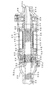
まず、本発明の制御パラメータの設定方法を適用した一実施形態および本発明の電気式動力舵取装置を適用した一実施形態に係る電気式動力舵取装置20の構成等を図1〜4に基づいて説明する。
【0019】
図1および図4に示すように、本実施形態に係る電気式動力舵取装置20は、主に、ステアリングホイール21、ステアリング軸22、ピニオン軸23、ラック軸24、トルクセンサ30、モータ40、モータレゾルバ44、ボールねじ機構50、ECU60等から構成されており、ステアリングホイール21による操舵状態をトルクセンサ30により検出し、その操舵状態に応じたアシスト力をモータ40により発生させて運転者による操舵をアシストするものである。なお、ラック軸24の両側には、それぞれタイロッド等を介して図略の車輪が連結されている。
【0020】
即ち、図1および図2に示すように、ステアリングホイール21には、ステアリング軸22の一端側が連結され、このステアリング軸22の他端側には、ピニオンハウジング25内に収容されたトルクセンサ30の入力軸23aおよびトーションバー31がピン32により連結されている。またこのトーションバー31の他端側31aには、ピニオン軸23の出力軸23bがスプライン結合によって連結されている。
【0021】
このピニオン軸23の入力軸23aはベアリング33aにより、また出力軸23bもベアリング33bにより、それぞれピニオンハウジング25内を回動自在に軸受されており、さらに入力軸23aとピニオンハウジング25との間には、第1レゾルバ35が、また出力軸23bとピニオンハウジング25との間には、第2レゾルバ37が、それぞれ設けられている。トルクセンサ30を構成する第1レゾルバ35および第2レゾルバ37は、ステアリングホイール21による操舵角を検出し得るもので、端子39を介してECU60にそれぞれ電気的に接続されている(図4参照)。
【0022】
ピニオン軸23の出力軸23bの端部には、ピニオンギヤ23cが形成されており、このピニオンギヤ23cにはラック軸24のラック溝24aが噛合可能に連結されている。これにより、ラックアンドピニオン式の操舵機構を構成している。
【0023】
図1および図3に示すように、ラック軸24は、ラックハウジング26およびモータハウジング27内に収容されており、その中間部には、螺旋状にボールねじ溝24bが形成されている。このボールねじ溝24bの周囲には、ラック軸24と同軸に回転可能にベアリング29により軸受される円筒形状のモータ軸43が設けられている。このモータ軸43は、ステータ41や励磁コイル42等とともにモータ40を構成するもので、ステータ41に巻回された励磁コイル42により発生する界磁が、回転子に相当するモータ軸43の外周に設けられた永久磁石45に作用することより、モータ軸43が回転し得るように構成されている。
【0024】
モータ軸43は、その内周にボールねじナット52が取り付けられており、このボールねじナット52にも、螺旋状にボールねじ溝52aが形成されている。そのため、このボールねじナット52のボールねじ溝52aとラック軸24のボールねじ溝24bとの間に多数のボール54を転動可能に介在させることによって、モータ軸43の回転によりラック軸24を軸方向に移動可能なボールねじ機構50を構成することができる。
【0025】
即ち、両ボールねじ溝24b、52a等から構成されるボールねじ機構50により、モータ軸43の正逆回転の回転トルクをラック軸24の軸線方向における往復動に変換することができる。これにより、この往復動は、ラック軸24とともにラックアンドピニオン式の操舵機構を構成するピニオン軸23を介してステアリングホイール21の操舵力を軽減するアシストカとなる。
【0026】
なお、モータ40のモータ軸43とモータハウジング27との間には、モータ軸43の回転角(電気角)θMeを検出し得るモータレゾルバ44が設けられており、このモータレゾルバ44は図略の端子を介してECU60に電気的に接続されている(図4参照)。このモータレゾルバ44は、特許請求の範囲に記載の「第3レゾルバ」に相当するものである。
【0027】
ECU60は、CPU61、不揮発性メモリ62、バッファアンプ63、64、65等から構成されている。CPU61には、バッファアンプ63、64、65を介して、第1レゾルバ35、第2レゾルバ37およびモータレゾルバ44が電気的に接続されているほか、システムバスを介して不揮発性メモリ62や図略の主記憶装置としての半導体メモリ装置等が接続されている。なお、この主記憶装置には、後述する制御パラメータ設定処理に関するプログラム等が格納されている。このECU60は、特許請求の範囲に記載の「制御手段」に相当するもので、また不揮発性メモリ62は、特許請求の範囲に記載の「記憶手段」に相当するもので、例えばフラッシュメモリ等のEEPROMやハードディスク装置等の磁気記憶装置あるいはMOディスク装置の光磁気記憶装置等が用いられる。
【0028】
なお、第1レゾルバ35、第2レゾルバ37およびモータレゾルバ44の構成および電気的特性については、本願出願人による特開2003−75109号公報、特願2002−196131号の明細書、特願2003−73807号の明細書等に詳細に開示されているので、これらを参照されたい。
【0029】
このように構成することにより、ステアリング軸22の回転角、即ちステアリングホイール21の回転角(ピニオン軸側の機械角)θTmを、第1レゾルバ35による第1操舵角θT1および第2レゾルバ37による第2操舵角θT2により検出することができる。また第1操舵角θT1と第2操舵角θT2との角度差や、角度比等からトーションバー31の捻れ量(操舵トルクに対応するもの)を捻れ角として検出することができる。
【0030】
そして、このトーションバー31の捻れ角度である相対回転角度差△θとトーションバー31の剛性とから操舵トルクTを算出することができるので、この操舵トルクTに応じて操舵力をアシストするための公知のアシスト制御をECU60のCPU61によって行なうことで、前述したモータ40により発生する操舵力によって運転者よる操舵をアシストすることができる。
【0031】
ここで、トルクセンサ30を構成する一方の第1レゾルバ35は、対極数5で電気的には5組のN極、S極を有することから、第1レゾルバ35から得られる第1操舵角(電気角)θT1には、ステアリングホイール21の1回転(360度)につき、5つのピーク点ができる。またこの第1レゾルバ35は、機械角360°に対して360°×5=1800°に相当する電気角を出力し得るため、電気角360°のレゾルバより5倍の分解能を有する。
【0032】
これに対し、トルクセンサ30を構成する他方の第2レゾルバ37から得られる第2操舵角(電気角)θT2には、ステアリングホイール21の1回転(360度)につき6つのピーク点ができる。これは、第2レゾルバ37が対極数6のレゾルバであり、電気的には6組のN極、S極を有することから、機械角360°に対して360°×6=2160°に相当する電気角を出力し得る。つまり、当該第2レゾルバ37は、電気角360°のレゾルバより6倍の分解能を有する。
【0033】
このように、第1レゾルバ35はレゾルバ出力信号として電気角θT1を、また第2レゾルバ37はレゾルバ出力信号として電気角θT2をそれぞれ出力するが、図5からわかるように、両信号波形は同じステアリングホイール21の回転角において同じ値をとることはない。そのため、第1レゾルバ35の電気角θT1と第2レゾルバ37の電気角θT2とに基づいて、CPU61による演算処理を行うことにより、ステアリングホイール21の1回転に対して、高分解能の機械角θTmを得ることができる。
【0034】
ところが、図5からわかるように、本実施形態に係る電気式動力舵取装置20では、ステアリングホイール21が中立点を中心に左右2回転づつ回転し得ることから、トルクセンサ30を構成する第1、第2レゾルバ35、37だけでは、各回転量(A=1、0、−1、−2)を特定することができない。そこで、モータレゾルバ44によりモータ40のモータ回転角(電気角θMe)を検出し、さらに演算モータ電気角θMe(A)を算出する処理をECU60により行う。
【0035】
即ち、次式(1) による演算処理によって、A=1、0、−1、−2に対応する4つの演算モータ電気角θMe(1) 、θMe(0) 、θMe(-1)、θMe(-2)を算出し、さらに4個の演算モータ電気角θMe(A)を所定範囲内に丸めた後、実際のモータ電気角θMe(以下、演算モータ電気角θMe(A)と区別するため、「実モータ電気角θMe」という。)に最も近いものを各回転量(A=1、0、−1、−2)の中から選択する。
【0036】
θMe(A) =(θTm +360×A)×r ・・・(1)
【0037】
なお、rは、ボールねじ機構50の減速ギヤ比とモータレゾルバ44の対極数との積による演算値で、小数点以下の数値を有する非整数となる値である。例えば、ボールねじ機構50の減速ギヤ比が8.2、モータレゾルバ44の対極数が7に設定される場合には、当該演算値rは57.4(=8.2×7)となる。
【0038】
これにより、図5に示すように、ステアリングホイール21が左右1回転以上の有限回転数内で回転する場合であっても、トルクセンサ30を構成する第1レゾルバ35、第2レゾルバ37およびモータレゾルバ44により、ステアリングホイール21の絶対回転位置を検出することができる。
【0039】
ここで、演算値rは、ステアリングホイール21の回転量とモータ40の回転量との比(回転比)Mrev と、モータ40の対極数Pとの積(r=Mrev ×P)により求められる。この回転比Mrev は、ステアリングホイール21が1回転したときのモータ40の回転数としても表現することができ、前述したように、比ストロークSをリードLにより除算することで求められる。即ち、ステアリングホイール21が1回転したときのラック軸24の移動量である比ストロークSを、モータ40が1回転したときのラック軸24の移動量であるリードLで割ることにより回転比Mrev を求めることができ(Mrev =S/L)、この値には通常、予め決定された設計値等が所定値として設定されている。
【0040】
しかしながら、[発明が解決しようとする課題]のところで述べたように、この回転比Mrev に設計値等の所定値を設定した場合には、操舵機構を構成するピニオン軸23のピニオンギヤ23cやラック軸24のラック溝24a等といった機構部品に加工誤差やバラツキ等が生じると、所定値に設定された回転比Mrev に対して誤差を与えることから、当該回転比Mrev に含まれる誤差が、回転比Mrev と対極数Pとの積により求められる演算値rにも直接影響を与える。その結果、前掲の式(1) により算出される演算モータ電気角θMe(A)の精度を低下させ、ひいては各回転量(A=1、0、−1、−2)の中から実モータ電気角θMeに最も近いものを選択する際に、誤った選択を誘因し得る。
【0041】
そこで、本実施形態に係る電気式動力舵取装置20では、図6に示す制御パラメータ設定処理によって、このような誤差を含み難い回転比Mrev を算出し、これを制御パラメータとして設定することを可能にしている。なお、この図6に示す制御パラメータ設定処理は、例えば、ECU60を構成する主記憶装置にロードされるプログラムをCPU61が実行することにより行われるものである。
【0042】
図6に示すように、制御パラメータ設定処理では、まずステップS101〜S107により、所定角度以上の範囲で変化する各レゾルバの電気角θT1、θT2、θMeを積算する処理が行われる。
即ち、ステップS101により第1レゾルバ35により検出される第1操舵角(電気角)θT1、第2レゾルバ37により検出される第2操舵角(電気角)θT2、モータレゾルバ44により検出されるモータ軸43の実モータ電気角θMeを取得した後、ステップS103により、電気角θT1、θT2からステアリングホイール21の機械角(ピニオン軸23側の機械角)θTmを算出する処理を行い、これにより算出された機械角θTmと実モータ電気角θMeとをそれぞれ前回算出されたものに積算する処理をステップS105により行う。
【0043】
そして、当該積算処理が所定角度以上の範囲で行われたか否かをステップS107により判断し、所定角度以上の範囲で積算されていると判断できない場合には(S107でNo)、ステップS101に戻ってステップS105までの処理を行い、さらに機械角θTmおよび実モータ電気角θMeを積算する。なお、ステップS107に判断される「所定角度以上の範囲」の所定角度は、例えばステアリングホイール21の4回転分あたる1440度や1回転分あたる360度あるいは1/4回転分にあたる90度等に設定される。一方、ステップS107により所定角度以上の範囲で積算されていると判断できる場合には(S107でYes)、続くステップS109によりステアリングホイール21とモータ40の回転比Mrev を算出する処理を行う。
【0044】
ステップS109では、ステップS101〜S107により積算された、ステアリングホイール21の機械角θTmとモータ40の実モータ電気角θMeとに基づいて、次式(2) によりステアリングホイール21とモータ40との回転比Mrev を算出する処理が行われる。なお同式でPはモータ40の対極数を示す。
【0045】
Mrev =∫θMe/(∫θTm ×P) ・・・(2)
【0046】
例えば、ステップS101〜S107によって、ステアリングホイール21の4回転分あたる1440度分の機械角θTmおよび実モータ電気角θMeが積算されている場合には、例えば、∫θMeとして82656(=1440×57.4)、∫θTm ×Pとして10080(=1440×7)が得られることから、回転比Mrev として8.2(=82656/10080)が算出される。なお本ステップは、特許請求の範囲に記載の「回転比算出手段」に相当するものである。
【0047】
続くステップS111では、ステップS109により算出された回転比Mrev を電気式動力舵取装置20の制御パラメータに設定する処理が行われる。このステップS111は、特許請求の範囲に記載の「パラメータ設定手段」に相当するものである。例えば、前掲の式(1) の演算値r(=Mrev ×P)を求める際に用いられる制御パラメータとして設定される。前述の例では、回転比Mrev として8.2が得られているので、この回転比Mrev を制御パラメータとして設定することにより、演算値rには57.4(=8.2×7)が与えられる。
【0048】
このように回転比Mrev を必要に応じて本制御パラメータ設定処理によりリアルタイムに設定しても良いが、これではECU60のCPU61に演算処理負担が高まるので、一度求めた回転比Mrev をメモリ装置に記憶し、必要時にそれから読み出すという処理形態を採った方がCPU61の処理負担を軽減することができる。なお、本制御パラメータ設定処理により回転比Mrev を定期的(例えば10分ごとや1時間ごと等)に設定することによって、温度変化や経時変化等により操舵機構の機構部品等にバラツキ等が生じた場合にも、当該バラツキ等に適応した回転比Mrev を制御パラメータとして設定することができる。この場合、所定期間を計時するタイマ処理等により本制御パラメータ設定処理が定期的に起動される。
【0049】
そこで、次のステップS113では、ステップS109により算出された回転比Mrev を不揮発性メモリに書き込む処理が行われる。具体的には、例えば、ECU60を構成する不揮発性メモリ62(例えばフラッシュメモリ等のEEPROM)に回転比Mrev に関する情報(データ)が書き込まれることにより、それに記憶される。これにより、例えば、電気式動力舵取装置20の出荷時の検査工程や出荷後のメンテナンス工程等において、本制御パラメータ設定処理が実行されることにより、算出された回転比Mrev をECU60に記憶することができる。
【0050】
以上説明したように、本実施形態に係る電気式動力舵取装置20によると、第1レゾルバ35により検出された第1操舵角θT1および第2レゾルバ37により検出された第2操舵角θT2から求められるステアリングホイール21の機械角θTmと、モータレゾルバ44により検出されたモータ40の実モータ電気角θMeとに基づいてステアリングホイール21の機械角θTmとモータ40との回転比Mrev を求め(S109)、この回転比Mrev を、第1操舵角θT1、第2操舵角θT2および実モータ電気角θMeからステアリングホイール21の演算モータ電気角θMe(A)(A=−2、−1、0、1)を求めるための前掲の式(1) の演算値r(=Mrev ×P)を与える際に用いられる制御パラメータに設定する(S111)。
【0051】
これにより、例えば、実際に操舵機構を構成しているピニオン軸23のピニオンギヤ23cやラック軸24のラック溝24a等に生じ得る加工誤差やバラツキ等を含めてこれらから当該回転比Mrev を求めることができる。したがって、このように操舵機構等の機構部品個々に生じ得る誤差等を含めて求められた当該回転比Mrev を電気式動力舵取装置20の制御パラメータとして設定することができるので、電気式動力舵取装置20に対してステアリングホイール21の絶対回転位置を正確に検出可能にする制御パラメータを設定することができる。またこのような回転比Mrev が設定された電気式動力舵取装置20は、ステアリングホイール21の絶対回転位置を正確に検出し、当該絶対回転位置に基づいて操舵をアシストするモータ40を制御することができる。
【0052】
なお、上述した実施形態では、電気式動力舵取装置20を例示して説明したが、本発明の実施形態はこれに限られることはなく、例えば、本実施形態の電気式動力舵取装置20を構成するECU60を電気式動力舵取装置20とは別個独立のコンピュータシステム(CPU、メモリ装置、入出力装置、インタフェイス装置等を含むもの)により構成し、図6に示す制御パラメータ設定処理をこのコンピュータシステムに実行させる、制御パラメータ設定装置を構築しても良い。この場合に求められた回転比Mrev は、電気式動力舵取装置20のECU60を構成するメモリ装置(不揮発性メモリを含む)に記憶されることとなるが、これにより、電気式動力舵取装置20のECU60に負担をかけることなく、回転比Mrev を電気式動力舵取装置20に設定することができる。
【図面の簡単な説明】
【図1】本発明の第1実施形態に係る電気式動力舵取装置の構成を示す構成図である。
【図2】図1に示す一点鎖線IIによる楕円内の拡大図である。
【図3】図1に示す一点鎖線III による楕円内の拡大図である。
【図4】本第1実施形態の電気式動力舵取装置を制御するECUとレゾルバとの接続構成を示すブロック図である。
【図5】ステアリングホイールの回転角に対する第1レゾルバおよび第2レゾルバによるレゾルバ出力信号、ステアリングホイールの機械角を示す特性図である。
【図6】図4に示すECUにより実行される制御パラメータ設定処理の流れを示すフローチャートである。
【符号の説明】
20 電気式動力舵取装置
21 ステアリングホイール
22 ステアリング軸
23 ピニオン軸
23c ピニオンギヤ
24 ラック軸
24a ラック溝
30 トルクセンサ
35 第1レゾルバ
37 第2レゾルバ
40 モータ
44 モータレゾルバ(第3レゾルバ)
50 ボールねじ機構
60 ECU(制御手段、回転比算出手段、パラメータ設定手段)
61 CPU
62 不揮発性メモリ(記憶手段)
θT1 第1レゾルバの電気角(第1操舵角)
θT2 第2レゾルバの電気角(第2操舵角)
θMe 実モータ電気角(モータ電気角)
θTm 機械角
θMe(A) 演算モータ電気角
S109(回転比算出手段)、S111(パラメータ設定手段)[0001]
BACKGROUND OF THE INVENTION
The present invention relates to a control parameter setting method, a control parameter setting device, and an electric power steering device.
[0002]
[Prior art]
2. Description of the Related Art Conventionally, there is known an electric power steering apparatus that reduces the steering force by a steering wheel by applying an assist force by a motor to a steering mechanism coupled to a steering shaft. In such an electric power steering apparatus, since the steering wheel rotates within a finite number of rotations of one or more left and right, the “position of the steering wheel where the vehicle goes straight” is set as a neutral position, and anything from the neutral position to the left or right is determined. The steering angle is grasped by detecting whether the steering wheel is located at the rotational position of the degree by the sensor as an absolute position.
[0003]
As the sensor for detecting the steering angle by such a steering wheel, for example, an “absolute position detection device” disclosed in
[0004]
[Patent Document 1]
Japanese Unexamined Patent Publication No. 2003-75109 (paragraph numbers 0042 to 0071, FIGS. 7 and 8)
[0005]
[Problems to be solved by the invention]
However, according to the “absolute position detection device” disclosed in
[0006]
For this reason, for example, if there is a processing error or variation in the pinion gear or rack groove constituting the rack and pinion mechanism, an error is given to the rotation ratio due to the planned design value, etc. As a result of giving an error to the quantitative deviation of the waveform, it is difficult to accurately detect the absolute rotational position of the steering wheel.
[0007]
The present invention has been made to solve the above-described problems, and an object of the present invention is to set a control parameter capable of accurately detecting the absolute rotational position of the steering wheel for the electric power steering apparatus. It is an object to provide a control parameter setting method and a control parameter setting device.
Another object of the present invention is to provide an electric power steering apparatus that can accurately detect the absolute rotational position of a steering wheel and control a motor that assists steering based on the absolute rotational position. .
[0008]
[Means for solving the problems and functions and effects of the invention]
In order to achieve the above object, according to the control parameter setting method of the first aspect, a first resolver for detecting a first steering angle which is a rotation angle of a steering shaft coupled to a steering wheel, and a counter electrode different from the first resolver. A second resolver that detects a second steering angle that is a rotation angle of the steering shaft, and a rack-and-pinion steering mechanism that has a rack shaft that engages with the pinion shaft. A motor that assists in driving the rack shaft, a third resolver that detects a motor electrical angle that is a rotation angle of the motor, the first steering angle, the second steering angle, and the motor electrical angle. Control means for controlling the motor based on the absolute rotational position of the steering wheel, and a control parameter for the electric power steering apparatus. Data setting method, based on the pinion shaft side mechanical angle obtained from the first steering angle and the second steering angle and the motor electrical angle of the motor, the pinion shaft and the motor A rotation ratio is obtained, and this rotation ratio is set in the control means as a control parameter used for obtaining an absolute rotation position of the steering wheel from the first steering angle, the second steering angle and the motor electrical angle. Is a technical feature.
[0009]
In order to achieve the above object, in the control parameter setting device according to
[0010]
In the first and third aspects of the invention, the rotation ratio between the pinion shaft and the motor is determined based on the mechanical angle on the pinion shaft side determined from the first steering angle and the second steering angle and the motor electrical angle of the motor. The rotation ratio is obtained and set in the control means as a control parameter used for obtaining the absolute rotation position of the steering wheel from the first steering angle, the second steering angle, and the motor electrical angle.
[0011]
The mechanical angle on the pinion shaft side is obtained by detecting the rotation angle of the steering shaft as the pinion shaft constituting the steering mechanism by the first resolver and the second resolver, and the motor electrical angle of the motor is the third resolver. Is detected. Thereby, for example, the rotation ratio can be obtained from these, including processing errors and variations that may occur in the pinion gear, the rack groove, and the like that actually constitute the steering mechanism. Therefore, since the rotation ratio obtained in this way including errors and the like that can occur in each of the mechanical components such as the steering mechanism can be set as a control parameter of the electric power steering apparatus, the electric power steering apparatus On the other hand, it is possible to set a control parameter that makes it possible to accurately detect the absolute rotational position of the steering wheel. Moreover, the electric power steering apparatus in which such a rotation ratio is set can accurately detect the absolute rotation position of the steering wheel.
[0012]
According to a second aspect of the present invention, there is provided a control parameter setting method according to the first aspect, wherein the control means includes storage means, and the rotation ratio or the control parameter is stored in the storage means. And
[0013]
Further, in the control parameter setting device according to
[0014]
In the invention of
[0015]
The electric power steering apparatus according to
[0016]
Furthermore, the electric power steering apparatus according to
[0017]
In the invention of
[0018]
DETAILED DESCRIPTION OF THE INVENTION
Hereinafter, embodiments of a control parameter setting method, a control parameter setting device, and an electric power steering device according to the present invention will be described with reference to the drawings.
First, the configuration of an electric
[0019]
As shown in FIGS. 1 and 4, the electric
[0020]
That is, as shown in FIGS. 1 and 2, one end side of a steering
[0021]
The input shaft 23a of the
[0022]
A pinion gear 23c is formed at an end portion of the output shaft 23b of the
[0023]
As shown in FIGS. 1 and 3, the
[0024]
A
[0025]
In other words, the rotational torque of the motor shaft 43 rotating in the forward and reverse directions can be converted into the reciprocating motion in the axial direction of the
[0026]
A
[0027]
The
[0028]
The configurations and electrical characteristics of the
[0029]
With this configuration, the rotation angle of the steering
[0030]
Since the steering torque T can be calculated from the relative rotation angle difference Δθ, which is the twist angle of the
[0031]
Here, one of the
[0032]
In contrast, the second steering angle (electrical angle) θT2 obtained from the other
[0033]
Thus, the
[0034]
However, as can be seen from FIG. 5, in the electric
[0035]
That is, four arithmetic motor electrical angles θMe (1), θMe (0), θMe (-1), θMe (corresponding to A = 1, 0, −1, −2 are obtained by arithmetic processing according to the following expression (1). -2) and further rounding the four arithmetic motor electrical angles θMe (A) into a predetermined range and then distinguishing them from the actual motor electrical angle θMe (hereinafter, the arithmetic motor electrical angle θMe (A)) The one closest to “actual motor electrical angle θMe”) is selected from each rotation amount (A = 1, 0, −1, −2).
[0036]
θMe (A) = (θTm + 360 × A) × r (1)
[0037]
Note that r is an arithmetic value obtained by the product of the reduction gear ratio of the
[0038]
As a result, as shown in FIG. 5, even when the steering wheel 21 rotates within a finite rotation speed of one or more left and right rotations, the
[0039]
Here, the calculation value r is obtained by the product (r = Mrev × P) of the ratio (rotation ratio) Mrev between the rotation amount of the steering wheel 21 and the rotation amount of the
[0040]
However, as described in [Problems to be Solved by the Invention], when a predetermined value such as a design value is set for the rotation ratio Mrev, the pinion gear 23c of the
[0041]
Therefore, in the electric
[0042]
As shown in FIG. 6, in the control parameter setting process, first, in steps S101 to S107, a process of integrating the electrical angles θT1, θT2, and θMe of each resolver that changes within a predetermined angle or more is performed.
That is, the first steering angle (electrical angle) θT1 detected by the
[0043]
Then, it is determined in step S107 whether or not the integration process has been performed in a range of a predetermined angle or more. If it cannot be determined that the integration is performed in a range of a predetermined angle or more (No in S107), the process returns to step S101. Then, the processing up to step S105 is performed, and the mechanical angle θTm and the actual motor electrical angle θMe are integrated. The predetermined angle in the “range above the predetermined angle” determined in step S107 is set to, for example, 1440 degrees corresponding to four rotations of the steering wheel 21, 360 degrees corresponding to one rotation, 90 degrees corresponding to ¼ rotation, or the like. Is done. On the other hand, if it can be determined in step S107 that the accumulated angle is greater than or equal to a predetermined angle (Yes in S107), a process of calculating the rotation ratio Mrev of the steering wheel 21 and the
[0044]
In step S109, based on the mechanical angle θTm of the steering wheel 21 and the actual motor electrical angle θMe of the
[0045]
Mrev = ∫θMe / (∫θTm × P) (2)
[0046]
For example, when the mechanical angle θTm and the actual motor electrical angle θMe for 1440 degrees corresponding to four rotations of the steering wheel 21 are integrated in steps S101 to S107, for example, 82656 (= 1440 × 57. 4) Since 10080 (= 1440 × 7) is obtained as ∫θTm × P, 8.2 (= 82656/10080) is calculated as the rotation ratio Mrev. This step corresponds to “rotation ratio calculation means” described in the claims.
[0047]
In subsequent step S111, a process of setting the rotation ratio Mrev calculated in step S109 as a control parameter of the electric
[0048]
As described above, the rotation ratio Mrev may be set in real time by the present control parameter setting process as necessary. However, this increases the processing load on the CPU 61 of the
[0049]
Therefore, in the next step S113, a process of writing the rotation ratio Mrev calculated in step S109 into the nonvolatile memory is performed. Specifically, for example, information (data) relating to the rotation ratio Mrev is written into a nonvolatile memory 62 (for example, EEPROM such as a flash memory) constituting the
[0050]
As described above, according to the electric
[0051]
As a result, for example, the rotation ratio Mrev can be obtained from these, including processing errors and variations that may occur in the pinion gear 23c of the
[0052]
In the above-described embodiment, the electric
[Brief description of the drawings]
FIG. 1 is a configuration diagram showing a configuration of an electric power steering apparatus according to a first embodiment of the present invention.
FIG. 2 is an enlarged view of an ellipse taken along one-dot chain line II shown in FIG.
FIG. 3 is an enlarged view of an ellipse taken along one-dot chain line III shown in FIG.
FIG. 4 is a block diagram showing a connection configuration between an ECU that controls the electric power steering apparatus of the first embodiment and a resolver.
FIG. 5 is a characteristic diagram showing resolver output signals from the first resolver and the second resolver and the mechanical angle of the steering wheel with respect to the rotation angle of the steering wheel.
6 is a flowchart showing a flow of control parameter setting processing executed by the ECU shown in FIG.
[Explanation of symbols]
20 Electric power steering device
21 Steering wheel
22 Steering shaft
23 Pinion shaft
23c pinion gear
24 rack shaft
24a Rack groove
30 Torque sensor
35 First resolver
37 Second resolver
40 motor
44 Motor resolver (third resolver)
50 Ball screw mechanism
60 ECU (control means, rotation ratio calculation means, parameter setting means)
61 CPU
62 Nonvolatile memory (storage means)
θT1 First resolver electrical angle (first steering angle)
θT2 Second resolver electrical angle (second steering angle)
θMe Actual motor electrical angle (motor electrical angle)
θTm Mechanical angle
θMe (A) Calculation motor electrical angle
S109 (rotation ratio calculation means), S111 (parameter setting means)
Claims (6)
前記第1操舵角および前記第2操舵角から求められる前記ピニオン軸側の機械角と前記モータの前記モータ電気角とに基づいて前記ピニオン軸と前記モータとの回転比を求め、この回転比を、前記第1操舵角、前記第2操舵角および前記モータ電気角から前記ステアリングホイールの絶対回転位置を求めるために用いられる制御パラメータとして前記制御手段に設定することを特徴とする制御パラメータの設定方法。A first resolver that detects a first steering angle that is a rotation angle of a steering shaft connected to a steering wheel, and a second steering angle that is a rotation angle of the steering shaft that has a different number of counter poles from the first resolver. A rack and pinion type steering mechanism having a rack shaft that engages with the pinion shaft, a motor that assists driving of the rack shaft, and a rotation angle of the motor. A third resolver for detecting a motor electrical angle; and a control means for controlling the motor based on an absolute rotational position of the steering wheel obtained from the first steering angle, the second steering angle and the motor electrical angle; A control parameter setting method for an electric power steering apparatus comprising:
A rotation ratio between the pinion shaft and the motor is obtained based on a mechanical angle on the pinion shaft side obtained from the first steering angle and the second steering angle and the motor electrical angle of the motor, and the rotation ratio is calculated. And setting the control means as a control parameter used to obtain an absolute rotational position of the steering wheel from the first steering angle, the second steering angle and the motor electrical angle. .
前記第1操舵角および前記第2操舵角から求められる前記ピニオン軸側の機械角と前記モータの前記モータ電気角とに基づいて前記ピニオン軸と前記モータとの回転比を求める回転比算出手段と、
前記求められた回転比を、前記第1操舵角、前記第2操舵角および前記モータ電気角から前記ステアリングホイールの絶対回転位置を求めるために用いられる制御パラメータとして前記制御手段に設定するパラメータ設定手段と、
を備えることを特徴とする制御パラメータの設定装置。A first resolver that detects a first steering angle that is a rotation angle of a steering shaft connected to a steering wheel, and a second steering angle that is a rotation angle of the steering shaft that has a different number of counter poles from the first resolver. A rack and pinion type steering mechanism having a rack shaft that engages with the pinion shaft, a motor that assists driving of the rack shaft, and a rotation angle of the motor. A third resolver for detecting a motor electrical angle; and a control means for controlling the motor based on an absolute rotational position of the steering wheel obtained from the first steering angle, the second steering angle and the motor electrical angle; A control parameter setting device for an electric power steering device comprising:
A rotation ratio calculating means for determining a rotation ratio between the pinion shaft and the motor based on a mechanical angle on the pinion shaft side obtained from the first steering angle and the second steering angle and the motor electrical angle of the motor; ,
Parameter setting means for setting the obtained rotation ratio in the control means as a control parameter used for obtaining the absolute rotation position of the steering wheel from the first steering angle, the second steering angle and the motor electrical angle. When,
A control parameter setting device comprising:
請求項1または2記載の制御パラメータの設定方法により設定された前記制御パラメータを用いて前記第1操舵角、前記第2操舵角および前記モータ電気角から求められた前記ステアリングホイールの絶対回転位置に基づいて前記モータを制御することを特徴とする電気式動力舵取装置。A first resolver that detects a first steering angle that is a rotation angle of a steering shaft connected to a steering wheel, and a second steering angle that is a rotation angle of the steering shaft that has a different number of counter poles from the first resolver. A rack and pinion type steering mechanism having a rack shaft that engages with the pinion shaft, a motor that assists driving of the rack shaft, and a rotation angle of the motor. A third resolver for detecting a motor electrical angle; and a control means for controlling the motor based on an absolute rotational position of the steering wheel obtained from the first steering angle, the second steering angle and the motor electrical angle; An electric power steering apparatus comprising:
The absolute rotation position of the steering wheel obtained from the first steering angle, the second steering angle, and the motor electrical angle using the control parameter set by the control parameter setting method according to claim 1 or 2. An electric power steering apparatus characterized in that the motor is controlled on the basis of the electric power steering apparatus.
請求項3または4記載の制御パラメータの設定装置により設定された前記制御パラメータを用いて前記第1操舵角、前記第2操舵角および前記モータ電気角から求められた前記ステアリングホイールの絶対回転位置に基づいて前記モータを制御することを特徴とする電気式動力舵取装置。A first resolver that detects a first steering angle that is a rotation angle of a steering shaft connected to a steering wheel, and a second steering angle that is a rotation angle of the steering shaft that has a different number of counter poles from the first resolver. A rack and pinion type steering mechanism having a rack shaft that engages with the pinion shaft, a motor that assists driving of the rack shaft, and a rotation angle of the motor. A third resolver for detecting a motor electrical angle; and a control means for controlling the motor based on an absolute rotational position of the steering wheel obtained from the first steering angle, the second steering angle and the motor electrical angle; An electric power steering apparatus comprising:
The absolute rotation position of the steering wheel obtained from the first steering angle, the second steering angle and the motor electrical angle using the control parameter set by the control parameter setting device according to claim 3 or 4. An electric power steering apparatus characterized in that the motor is controlled on the basis of the electric power steering apparatus.
Priority Applications (4)
| Application Number | Priority Date | Filing Date | Title |
|---|---|---|---|
| JP2003086785A JP3842235B2 (en) | 2003-03-27 | 2003-03-27 | Control parameter setting method, control parameter setting device, and electric power steering device |
| US10/806,401 US7032706B2 (en) | 2003-03-27 | 2004-03-23 | Setting method for control parameter, setting device for control parameter, and electric power steering device |
| EP04007234A EP1462341B1 (en) | 2003-03-27 | 2004-03-25 | Setting method for control parameter, setting device for control parameter, and electric power steering device |
| DE602004003983T DE602004003983T2 (en) | 2003-03-27 | 2004-03-25 | Method for setting a control parameter, control parameter setting device, and electric power steering device |
Applications Claiming Priority (1)
| Application Number | Priority Date | Filing Date | Title |
|---|---|---|---|
| JP2003086785A JP3842235B2 (en) | 2003-03-27 | 2003-03-27 | Control parameter setting method, control parameter setting device, and electric power steering device |
Publications (2)
| Publication Number | Publication Date |
|---|---|
| JP2004291807A JP2004291807A (en) | 2004-10-21 |
| JP3842235B2 true JP3842235B2 (en) | 2006-11-08 |
Family
ID=32821522
Family Applications (1)
| Application Number | Title | Priority Date | Filing Date |
|---|---|---|---|
| JP2003086785A Expired - Fee Related JP3842235B2 (en) | 2003-03-27 | 2003-03-27 | Control parameter setting method, control parameter setting device, and electric power steering device |
Country Status (4)
| Country | Link |
|---|---|
| US (1) | US7032706B2 (en) |
| EP (1) | EP1462341B1 (en) |
| JP (1) | JP3842235B2 (en) |
| DE (1) | DE602004003983T2 (en) |
Families Citing this family (14)
| Publication number | Priority date | Publication date | Assignee | Title |
|---|---|---|---|---|
| JP4042049B2 (en) * | 2003-04-16 | 2008-02-06 | 株式会社ジェイテクト | Steering angle detection device for electric power steering device |
| ES2277664T3 (en) * | 2004-03-10 | 2007-07-16 | Umbra Cuscinetti S.P.A. | STEERING UNIT FOR AN ELECTRIC VEHICLE. |
| JP4600653B2 (en) * | 2004-10-28 | 2010-12-15 | 株式会社ジェイテクト | Steering control device |
| JP4577020B2 (en) * | 2005-01-18 | 2010-11-10 | トヨタ自動車株式会社 | Vehicle steering device |
| JP2006258793A (en) * | 2005-02-16 | 2006-09-28 | Jtekt Corp | Torque detector, and bearing unit for supporting pinion shaft |
| JP4727283B2 (en) * | 2005-04-18 | 2011-07-20 | Ntn株式会社 | Multi-rotation absolute angle detection method and detection apparatus |
| RU2278797C1 (en) * | 2005-08-19 | 2006-06-27 | Открытое акционерное общество "Калужский завод электронных изделий" | Electromechanical steering booster and steering booster electric motor |
| JP4852964B2 (en) * | 2005-10-14 | 2012-01-11 | 日本精工株式会社 | Control device for electric power steering device |
| CN101875369B (en) * | 2009-04-30 | 2013-06-12 | 浙江中科德润科技有限公司 | Servo power-assisting steering system and a method for controlling same |
| JP2014015130A (en) * | 2012-07-09 | 2014-01-30 | Jtekt Corp | Steering device |
| JP5950459B2 (en) * | 2013-01-08 | 2016-07-13 | 日立オートモティブシステムズ株式会社 | Power steering device |
| CN103253304B (en) * | 2013-06-04 | 2016-01-20 | 安徽安凯汽车股份有限公司 | A kind of method of inspection of Rotary transformer type steering angle sensor of electronlmobil |
| CN103486965A (en) * | 2013-09-29 | 2014-01-01 | 杭州飞越汽车零部件有限公司 | Device for measuring steering angle and torque |
| JP6672652B2 (en) * | 2015-09-10 | 2020-03-25 | 株式会社ジェイテクト | Steering control device |
Family Cites Families (9)
| Publication number | Priority date | Publication date | Assignee | Title |
|---|---|---|---|---|
| US4897603A (en) * | 1988-02-29 | 1990-01-30 | Siemens Aktiengesellschaft | Arrangement for determining the speed and rotor position of an electric machine |
| DE19961884C2 (en) * | 1999-12-20 | 2003-08-21 | Thomas Strothmann | Arrangement for contactless detection of angles of rotation, torques and other, preferably rotational quantities between rotating parts |
| US6422335B1 (en) * | 2000-04-11 | 2002-07-23 | Trw Inc. | Method and apparatus for controlling steering feel with diagnostics |
| JP2002196131A (en) | 2000-12-27 | 2002-07-10 | Ando Electric Co Ltd | Fabry-perot etalon, wavelength monitor and wavelength variable light source with built-in wavelength monitor |
| JP3982739B2 (en) * | 2001-05-08 | 2007-09-26 | 本田技研工業株式会社 | Electric power steering device |
| US6535805B2 (en) | 2001-08-10 | 2003-03-18 | Delphi Technologies, Inc. | Robust determination of hand-wheel position |
| JP2003073807A (en) | 2001-08-27 | 2003-03-12 | Plasma Microtech Kk | Steel ball and surface treatment method therefor |
| JP3789791B2 (en) | 2001-09-05 | 2006-06-28 | 株式会社ジェイテクト | Absolute position detection apparatus and absolute position detection method |
| JP3969220B2 (en) | 2002-07-04 | 2007-09-05 | 株式会社ジェイテクト | Absolute position detection device and absolute position detection method for electric power steering device |
-
2003
- 2003-03-27 JP JP2003086785A patent/JP3842235B2/en not_active Expired - Fee Related
-
2004
- 2004-03-23 US US10/806,401 patent/US7032706B2/en active Active
- 2004-03-25 EP EP04007234A patent/EP1462341B1/en not_active Expired - Fee Related
- 2004-03-25 DE DE602004003983T patent/DE602004003983T2/en not_active Expired - Lifetime
Also Published As
| Publication number | Publication date |
|---|---|
| EP1462341A2 (en) | 2004-09-29 |
| EP1462341B1 (en) | 2007-01-03 |
| EP1462341A3 (en) | 2005-04-20 |
| US7032706B2 (en) | 2006-04-25 |
| US20040188170A1 (en) | 2004-09-30 |
| JP2004291807A (en) | 2004-10-21 |
| DE602004003983D1 (en) | 2007-02-15 |
| DE602004003983T2 (en) | 2007-10-11 |
Similar Documents
| Publication | Publication Date | Title |
|---|---|---|
| JP3842235B2 (en) | Control parameter setting method, control parameter setting device, and electric power steering device | |
| JP4675886B2 (en) | Control device for electric power steering device | |
| JP3891288B2 (en) | Electric power steering device | |
| JP4490401B2 (en) | Vehicle steering system | |
| CN103373386B (en) | Power steering gear and the control device of power steering gear | |
| JP3938902B2 (en) | Angle detection device and torque sensor including the same | |
| JP3969220B2 (en) | Absolute position detection device and absolute position detection method for electric power steering device | |
| CN108698640B (en) | Electric power steering apparatus and method for reducing torque ripple thereof | |
| JP2010048760A (en) | Anomaly detection unit for resolver and electric power steering apparatus | |
| EP2743645B1 (en) | Phase difference detector and rotation angle detection device including the same | |
| WO2012066942A1 (en) | Device and method for adjusting electric power steering device | |
| JP4042049B2 (en) | Steering angle detection device for electric power steering device | |
| JP2005091204A (en) | Electric power steering device | |
| JP4604551B2 (en) | Resolver signal arithmetic processing method and arithmetic processing apparatus | |
| JP2019207204A (en) | Rotation detector and electric power steering device using the same | |
| JP4281595B2 (en) | Angle detector | |
| JP2020165951A (en) | Detector and control device | |
| JP2003344109A (en) | Rotation angle detector and its temperature compensating method | |
| JP5045407B2 (en) | Resolver abnormality detection device and electric power steering device | |
| JP6503358B2 (en) | Method and apparatus for detecting the rotational angle and / or rotational speed of a motor shaft of a motor | |
| JP2020001531A (en) | Contact state detection device, method and program of detecting contact state | |
| CN105026907A (en) | Electric power steering device, and adjustment device and adjustment method for electric power steering device | |
| JP5950459B2 (en) | Power steering device | |
| US11697454B2 (en) | Variable travel stop to increase worm gear durability | |
| JP4189675B2 (en) | Electric power steering device for vehicle |
Legal Events
| Date | Code | Title | Description |
|---|---|---|---|
| A621 | Written request for application examination |
Free format text: JAPANESE INTERMEDIATE CODE: A621 Effective date: 20050629 |
|
| RD04 | Notification of resignation of power of attorney |
Free format text: JAPANESE INTERMEDIATE CODE: A7424 Effective date: 20050922 |
|
| A711 | Notification of change in applicant |
Free format text: JAPANESE INTERMEDIATE CODE: A712 Effective date: 20060301 |
|
| A977 | Report on retrieval |
Free format text: JAPANESE INTERMEDIATE CODE: A971007 Effective date: 20060725 |
|
| TRDD | Decision of grant or rejection written | ||
| A01 | Written decision to grant a patent or to grant a registration (utility model) |
Free format text: JAPANESE INTERMEDIATE CODE: A01 Effective date: 20060808 |
|
| A61 | First payment of annual fees (during grant procedure) |
Free format text: JAPANESE INTERMEDIATE CODE: A61 Effective date: 20060809 |
|
| R150 | Certificate of patent or registration of utility model |
Ref document number: 3842235 Country of ref document: JP Free format text: JAPANESE INTERMEDIATE CODE: R150 Free format text: JAPANESE INTERMEDIATE CODE: R150 |
|
| FPAY | Renewal fee payment (event date is renewal date of database) |
Free format text: PAYMENT UNTIL: 20090818 Year of fee payment: 3 |
|
| FPAY | Renewal fee payment (event date is renewal date of database) |
Free format text: PAYMENT UNTIL: 20100818 Year of fee payment: 4 |
|
| FPAY | Renewal fee payment (event date is renewal date of database) |
Free format text: PAYMENT UNTIL: 20110818 Year of fee payment: 5 |
|
| FPAY | Renewal fee payment (event date is renewal date of database) |
Free format text: PAYMENT UNTIL: 20120818 Year of fee payment: 6 |
|
| FPAY | Renewal fee payment (event date is renewal date of database) |
Free format text: PAYMENT UNTIL: 20130818 Year of fee payment: 7 |
|
| LAPS | Cancellation because of no payment of annual fees |