EP1283128A2 - Lighting arrangement for public transport vehicles - Google Patents
Lighting arrangement for public transport vehicles Download PDFInfo
- Publication number
- EP1283128A2 EP1283128A2 EP02396120A EP02396120A EP1283128A2 EP 1283128 A2 EP1283128 A2 EP 1283128A2 EP 02396120 A EP02396120 A EP 02396120A EP 02396120 A EP02396120 A EP 02396120A EP 1283128 A2 EP1283128 A2 EP 1283128A2
- Authority
- EP
- European Patent Office
- Prior art keywords
- handrail
- passenger cabin
- light source
- lighting arrangement
- public transport
- Prior art date
- Legal status (The legal status is an assumption and is not a legal conclusion. Google has not performed a legal analysis and makes no representation as to the accuracy of the status listed.)
- Withdrawn
Links
Images


Classifications
-
- B—PERFORMING OPERATIONS; TRANSPORTING
- B60—VEHICLES IN GENERAL
- B60Q—ARRANGEMENT OF SIGNALLING OR LIGHTING DEVICES, THE MOUNTING OR SUPPORTING THEREOF OR CIRCUITS THEREFOR, FOR VEHICLES IN GENERAL
- B60Q3/00—Arrangement of lighting devices for vehicle interiors; Lighting devices specially adapted for vehicle interiors
- B60Q3/40—Arrangement of lighting devices for vehicle interiors; Lighting devices specially adapted for vehicle interiors specially adapted for specific vehicle types
- B60Q3/41—Arrangement of lighting devices for vehicle interiors; Lighting devices specially adapted for vehicle interiors specially adapted for specific vehicle types for mass transit vehicles, e.g. buses
- B60Q3/43—General lighting
Definitions
- the invention relates to a lighting arrangement for public transport vehicles comprising a light source and a reflective surface for reflecting light emitted from the light source to a passenger cabin in a public transport vehicle, whereby the upper part of the passenger cabin in the public transport vehicle substantially comprises an upper structure arranged above the seats in the passenger cabin, the structure comprises one or more handrails in the passenger cabin.
- Public transport vehicles such as buses, minibuses, trams and trains, are typically illuminated using lighting fixtures attached to a ceiling structure of the vehicle.
- the lighting fixtures may for instance be implemented using fluorescent lamps, whereby the lighting fixtures should be fastened to the ceiling structure reliably and at the same time in a manner causing expenses owing to the large size of the lighting fixtures.
- the lighting can be implemented either as direct lighting or indirect lighting.
- An advantage with direct lighting is a high luminous efficiency, and such lighting is typically used in places where high illuminance is required.
- a drawback with direct lighting is that it may cause a discomfort glare to some seats, as the lighting fixture glares straight at the passenger's eyes.
- the lighting should be a comfortable general lighting that does not directly cause a discomfort glare to the passengers' eyes.
- the general lighting is often implemented as indirect lighting where the light sources are encased into a ceiling structure in such a manner that light is reflected from a case structure back towards the ceiling, and then from the ceiling as the general lighting of the passenger cabin.
- the structure of the lighting fixture becomes complicated and expensive, as the casing should be carried out reliably, and the structure should harmoniously be fitted with the interior design of the vehicle.
- handrails In order to make it easier for the passengers to move, public transport vehicles are generally provided with handrails, which the passengers may take hold of to obtain support or to improve their balance.
- Handrails are generally made of a metal bar, the diameter of which allows the passengers to grip the bar and to use it as a hand hold.
- the handrails are placed in the vehicles approximately at shoulder or head level of an average built passenger when the passenger is standing in the aisle of the vehicle. The handrails are thus placed above the seats in the vehicle, for instance in a bus or a train.
- Handrails may also be placed elsewhere in the vehicle. Such places may include the stairs at the exits of the vehicles as well as other locations where the handrail can be placed approximately at waist level without causing any inconvenience for the passengers while sitting down.
- Patent publication US 5,779,228 discloses a solution, where the lighting fixture is placed in a longitudinal cavity formed at the side of the handrail in the vehicle. The lighting fixture is then placed on the outer surface of the handrail and is used for illuminating both the handrail and the vehicle.
- Patent publication US 5,347,434 shows an illuminated bag-rack to be mounted on aircrafts.
- the publication discloses how an electroluminescent lamp implemented as an electroluminescent panel is placed at the edge of the bag-rack side of the handrail placed close to the bag-rack. Such a panel is intended to illuminate the signs placed at the edge of the luggage rack.
- This object is achieved with the arrangement of the invention, characterized in that the light source is arranged inside the handrail of the upper structure in the public transport vehicle, and that the handrail comprises one or more light-permeable apertures, and that the handrail apertures are arranged to direct the light generated from the light source to the upper structure of the passenger cabin in the public transport vehicle, the upper structure being arranged to function as the reflective surface for providing the passenger cabin with indirect lighting.
- the invention is based on the idea that the handrails in public transport vehicles can be utilized for positioning the light source in such a manner that the light source provides the passenger cabin of the vehicle with indirect lighting using already existing structures in the passenger cabin as the reflective surface.
- the arrangement of the invention enables to reduce the amount of equipment to be mounted to the passenger cabin, and no separate lighting units need to be fastened to the ceiling structure. Since the handrails must naturally be of strong design in order to serve as a support, the light sources can reliably be placed inside the handrails.
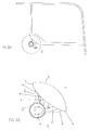
- Figures 1A and 1B show an embodiment of an arrangement of the invention.
- the Figures illustrate the cross section of an upper structure 1 in a bus, for instance, where the upper structure comprises a handrail 2 and a luggage rack 3.
- Figure 1B shows a portion referred to by letter A of the assembly shown in Figure 1A that shows the fastening of the luggage rack 3 to an interior wall 4 of the bus, and a vertical bar 6 fastening the handrail 2 and the luggage rack 3 to a ceiling structure 5 in the passenger cabin.
- the handrail 2 in the passenger cabin of the bus is placed in the vicinity of the luggage rack 3.
- the handrail 2 is placed in such a manner that it is substantially located at the same height as the luggage rack 3.
- the luggage rack is typically placed above the seats in the passenger cabin.
- the handrails 2 thus form such an object that the passengers standing in the passenger cabin can take hold of.
- the handrails in the passenger cabin vertically extend the entire length of the passenger cabin in the vehicle.
- the lighting fixture arrangement of the invention comprises a light source 7 placed inside the handrail 2 in the passenger cabin.
- the handrail also comprises one or more apertures, from which the light generated from the light source inside the handrail can be emitted.
- the apertures formed in the handrail are directed in such a manner that the light hits the upper structure 1 of the passenger cabin in the vicinity of the handrail, the upper structure being arranged to function as a reflective surface for providing the passenger cabin with indirect lighting.
- the light-permeable apertures in the handrail are formed, for instance, in such a manner that the metal handrail is provided with apertures of required width, which are further covered with light-permeable plastic or other corresponding material. Thus, no sharp edges are formed in the handrail that may be unpleasant when taking hold of the handrail.
- the upper structure 1 of the passenger cabin comprises a luggage rack 3 including an open edge 8.
- the open edge 8 of the luggage rack refers to in this context is the edge of the luggage rack, from which luggage can be lifted onto the rack.
- the open edge is thus the edge of the luggage rack that is located towards the middle of the passenger cabin in the vehicle.
- this open edge can be provided for instance with hinged lids, in which case the bags and belongings on the rack are reliably kept in position.
- the handrail 2 is arranged in the vicinity of the open edge of the luggage rack and substantially below an end 9 of the open edge.
- a lower surface 10 of the open edge is then arranged as a reflective surface in order to provide the passenger cabin with indirect lighting.
- the cross section of the lower surface 10 of the open edge in the luggage rack is made concave.
- the cross section of a corresponding lower surface 20 is made convex.
- the embodiments illustrated in Figures 1 and 2 are similar.
- the shape of the lower surfaces functioning as reflective surfaces provides differences on how light is distributed in the passenger cabin. A convex surface spreads light to a wider area in the horizontal direction than a concave surface.
- the cross section of the reflective surface may be arbitrarily selected without having an effect on the scope of the invention.
- the light source 7 to be positioned inside the handrail 2 is preferably a fluorescent lamp.
- a fluorescent lamp the most appropriate for this purpose is, for example, the T5-type fluorescent lamp having a small diameter.
- electrical and mechanical connections required by the fluorescent lamp should be arranged inside the tubular handrail, as well as wiring for supplying energy to the fluorescent lamps.
- An actuator supplying energy may be freely placed in a vehicle.
- Figures 3A and 3B show an embodiment of the invention.
- the upper structure of the passenger cabin is not provided with a luggage rack, whereby a portion of a wall 34 in the passenger cabin forms the reflective surface for providing the passenger cabin with indirect lighting.
- This type of solution is practical in such passenger cabins that do not include seats on one or both sides of the passenger cabin.
- Such a passenger cabin or portion of such a passenger cabin may for instance be an entry hall in trains or trams.
- the light from the light source inside the handrail is arranged to be emitted substantially upwards from the horizontal plane.
- the light is directed by directing the apertures in the handrail.
- light is directed towards the reflective surface in order to achieve indirect lighting, and the light is not allowed to be directed directly to other surfaces in order to prevent glare.
- Figures 1 and 2 show how the handrail 2 is placed in the vicinity of the luggage rack 3 in such a manner that the end of the luggage rack 3 surrounds the handrail at an approximately 90 degree angle.
- the handrail may also be provided with several apertures in order to direct a particularly accurate indirect lighting.
- the handrail aperture is formed such that a light source is emitted outside the handrail substantially at a 90 degree angle.
- the handrail 2 aperture is arranged so that the light source 7 emits light outside the handrail substantially upwards from the horizontal plane as is shown in Figures 1 and 2.
- the choice of the material of the reflective surface 10, 20 may considerably affect the quality of the indirect lighting.
- the choice of such a material may have an effect, for instance, on the brightness and tone of the light to be generated.
- the material can be selected to suit the interior design of the passenger cabin.
- the material used may for instance be composed of different types of cloth or plastic, whose surface material and color affect the amount and quality of the light.
- the apertures in the handrail are adjustable.
- the apertures of the handrail can be adjusted for instance in such a manner that the surface part of the handrail can be turned around the handrail.
- the apertures provided in the surface part thus move in relation to the apertures in the handrail, and the amount of light can therefore be changed.
- the adjustable apertures can also be implemented in such a manner that the handrail can be turned. Consequently, the direction can be adjusted to which the light can be emitted from the apertures of the bar.
- the adjustment is preferably implemented so that the handrail or the surface part thereof can be locked in position, whereby the lighting cannot accidentally be adjusted when the handrail is gripped.
- the reflective surface comprises a mounting bracket for mounting advertisements, messages or the like on the illuminated area.
- the advertisement or the like attached to the mounting bracket functions as the reflective surface providing indirect lighting to the passenger cabin.
- the advertisement or, for instance a sign is illuminated more powerfully than the environment thereof.
- Figure 4 shows a part of the passenger cabin in the arrangement of the invention.
- the luggage rack is placed above the seats 41 in the passenger cabin.
- a handrail 2 is still placed in the vicinity of the open edge 8 of the luggage rack, and a light source is invisibly arranged inside the handrail 2.
- the end part of the open luggage rack is made concave as shown in Figure 1 in order to provide indirect lighting to the passenger cabin.
Landscapes
- Engineering & Computer Science (AREA)
- Mechanical Engineering (AREA)
- Arrangements Of Lighting Devices For Vehicle Interiors, Mounting And Supporting Thereof, Circuits Therefore (AREA)
- Passenger Equipment (AREA)
Abstract
Description
- The invention relates to a lighting arrangement for public transport vehicles comprising a light source and a reflective surface for reflecting light emitted from the light source to a passenger cabin in a public transport vehicle, whereby the upper part of the passenger cabin in the public transport vehicle substantially comprises an upper structure arranged above the seats in the passenger cabin, the structure comprises one or more handrails in the passenger cabin.
- Public transport vehicles, such as buses, minibuses, trams and trains, are typically illuminated using lighting fixtures attached to a ceiling structure of the vehicle. The lighting fixtures may for instance be implemented using fluorescent lamps, whereby the lighting fixtures should be fastened to the ceiling structure reliably and at the same time in a manner causing expenses owing to the large size of the lighting fixtures.
- The lighting can be implemented either as direct lighting or indirect lighting. An advantage with direct lighting is a high luminous efficiency, and such lighting is typically used in places where high illuminance is required. A drawback with direct lighting is that it may cause a discomfort glare to some seats, as the lighting fixture glares straight at the passenger's eyes.
- Particularly on long journeys in such vehicles, the lighting should be a comfortable general lighting that does not directly cause a discomfort glare to the passengers' eyes. Hence, the general lighting is often implemented as indirect lighting where the light sources are encased into a ceiling structure in such a manner that light is reflected from a case structure back towards the ceiling, and then from the ceiling as the general lighting of the passenger cabin. Particularly in such a case, the structure of the lighting fixture becomes complicated and expensive, as the casing should be carried out reliably, and the structure should harmoniously be fitted with the interior design of the vehicle.
- In order to make it easier for the passengers to move, public transport vehicles are generally provided with handrails, which the passengers may take hold of to obtain support or to improve their balance. Handrails are generally made of a metal bar, the diameter of which allows the passengers to grip the bar and to use it as a hand hold. The handrails are placed in the vehicles approximately at shoulder or head level of an average built passenger when the passenger is standing in the aisle of the vehicle. The handrails are thus placed above the seats in the vehicle, for instance in a bus or a train.
- Handrails may also be placed elsewhere in the vehicle. Such places may include the stairs at the exits of the vehicles as well as other locations where the handrail can be placed approximately at waist level without causing any inconvenience for the passengers while sitting down.
- Patent publication US 5,779,228 discloses a solution, where the lighting fixture is placed in a longitudinal cavity formed at the side of the handrail in the vehicle. The lighting fixture is then placed on the outer surface of the handrail and is used for illuminating both the handrail and the vehicle.
- Patent publication US 5,347,434 shows an illuminated bag-rack to be mounted on aircrafts. The publication discloses how an electroluminescent lamp implemented as an electroluminescent panel is placed at the edge of the bag-rack side of the handrail placed close to the bag-rack. Such a panel is intended to illuminate the signs placed at the edge of the luggage rack.
- It is an object of the present invention to provide an arrangement that avoids the above drawbacks and allows implementing the general lighting in a vehicle in a simpler and more economical way than previously. This object is achieved with the arrangement of the invention, characterized in that the light source is arranged inside the handrail of the upper structure in the public transport vehicle, and that the handrail comprises one or more light-permeable apertures, and that the handrail apertures are arranged to direct the light generated from the light source to the upper structure of the passenger cabin in the public transport vehicle, the upper structure being arranged to function as the reflective surface for providing the passenger cabin with indirect lighting.
- The invention is based on the idea that the handrails in public transport vehicles can be utilized for positioning the light source in such a manner that the light source provides the passenger cabin of the vehicle with indirect lighting using already existing structures in the passenger cabin as the reflective surface.
- The arrangement of the invention enables to reduce the amount of equipment to be mounted to the passenger cabin, and no separate lighting units need to be fastened to the ceiling structure. Since the handrails must naturally be of strong design in order to serve as a support, the light sources can reliably be placed inside the handrails.
- In the following the invention will be described in greater detail by means of the preferred embodiments with reference to the accompanying drawings, in which
- Figures 1A, 1B, 2A, 2B, 3A and 3B illustrate embodiments of an arrangement of the invention, and
- Figure 4 shows how the arrangement of the invention can be positioned in a public transport vehicle.
-
- Figures 1A and 1B show an embodiment of an arrangement of the invention. The Figures illustrate the cross section of an
upper structure 1 in a bus, for instance, where the upper structure comprises ahandrail 2 and a luggage rack 3. Figure 1B shows a portion referred to by letter A of the assembly shown in Figure 1A that shows the fastening of the luggage rack 3 to aninterior wall 4 of the bus, and avertical bar 6 fastening thehandrail 2 and the luggage rack 3 to aceiling structure 5 in the passenger cabin. - In accordance with Figures 1A and 1B the
handrail 2 in the passenger cabin of the bus is placed in the vicinity of the luggage rack 3. In the embodiment, thehandrail 2 is placed in such a manner that it is substantially located at the same height as the luggage rack 3. In public transport vehicles the luggage rack is typically placed above the seats in the passenger cabin. Thehandrails 2 thus form such an object that the passengers standing in the passenger cabin can take hold of. In general, the handrails in the passenger cabin vertically extend the entire length of the passenger cabin in the vehicle. - The lighting fixture arrangement of the invention comprises a
light source 7 placed inside thehandrail 2 in the passenger cabin. The handrail also comprises one or more apertures, from which the light generated from the light source inside the handrail can be emitted. The apertures formed in the handrail are directed in such a manner that the light hits theupper structure 1 of the passenger cabin in the vicinity of the handrail, the upper structure being arranged to function as a reflective surface for providing the passenger cabin with indirect lighting. - The light-permeable apertures in the handrail are formed, for instance, in such a manner that the metal handrail is provided with apertures of required width, which are further covered with light-permeable plastic or other corresponding material. Thus, no sharp edges are formed in the handrail that may be unpleasant when taking hold of the handrail.
- In accordance with a preferred embodiment of the invention, the
upper structure 1 of the passenger cabin comprises a luggage rack 3 including anopen edge 8. What theopen edge 8 of the luggage rack refers to in this context is the edge of the luggage rack, from which luggage can be lifted onto the rack. The open edge is thus the edge of the luggage rack that is located towards the middle of the passenger cabin in the vehicle. However, this open edge can be provided for instance with hinged lids, in which case the bags and belongings on the rack are reliably kept in position. - Also according to a preferred embodiment of the invention the
handrail 2 is arranged in the vicinity of the open edge of the luggage rack and substantially below anend 9 of the open edge. Alower surface 10 of the open edge is then arranged as a reflective surface in order to provide the passenger cabin with indirect lighting. - In the embodiment shown in Figures 1A and 1B, the cross section of the
lower surface 10 of the open edge in the luggage rack is made concave. In the preferred embodiment shown in Figures 2A and 2B the cross section of a corresponding lower surface 20 is made convex. In other respects the embodiments illustrated in Figures 1 and 2 are similar. The shape of the lower surfaces functioning as reflective surfaces provides differences on how light is distributed in the passenger cabin. A convex surface spreads light to a wider area in the horizontal direction than a concave surface. The cross section of the reflective surface may be arbitrarily selected without having an effect on the scope of the invention. - The
light source 7 to be positioned inside thehandrail 2 is preferably a fluorescent lamp. Among the commercially available fluorescent lamps the most appropriate for this purpose is, for example, the T5-type fluorescent lamp having a small diameter. Thus, electrical and mechanical connections required by the fluorescent lamp should be arranged inside the tubular handrail, as well as wiring for supplying energy to the fluorescent lamps. An actuator supplying energy may be freely placed in a vehicle. - Figures 3A and 3B show an embodiment of the invention. In this embodiment the upper structure of the passenger cabin is not provided with a luggage rack, whereby a portion of a
wall 34 in the passenger cabin forms the reflective surface for providing the passenger cabin with indirect lighting. This type of solution is practical in such passenger cabins that do not include seats on one or both sides of the passenger cabin. Such a passenger cabin or portion of such a passenger cabin may for instance be an entry hall in trains or trams. - In the embodiments shown in Figures 1 and 2, the light from the light source inside the handrail is arranged to be emitted substantially upwards from the horizontal plane. The light is directed by directing the apertures in the handrail. In general, light is directed towards the reflective surface in order to achieve indirect lighting, and the light is not allowed to be directed directly to other surfaces in order to prevent glare. Figures 1 and 2 show how the
handrail 2 is placed in the vicinity of the luggage rack 3 in such a manner that the end of the luggage rack 3 surrounds the handrail at an approximately 90 degree angle. The handrail may also be provided with several apertures in order to direct a particularly accurate indirect lighting. In accordance with an embodiment of the invention, the handrail aperture is formed such that a light source is emitted outside the handrail substantially at a 90 degree angle. According to another embodiment of the invention thehandrail 2 aperture is arranged so that thelight source 7 emits light outside the handrail substantially upwards from the horizontal plane as is shown in Figures 1 and 2. - The choice of the material of the
reflective surface 10, 20 may considerably affect the quality of the indirect lighting. The choice of such a material may have an effect, for instance, on the brightness and tone of the light to be generated. The material can be selected to suit the interior design of the passenger cabin. The material used may for instance be composed of different types of cloth or plastic, whose surface material and color affect the amount and quality of the light. - According to an embodiment of the invention the apertures in the handrail are adjustable. The apertures of the handrail can be adjusted for instance in such a manner that the surface part of the handrail can be turned around the handrail. The apertures provided in the surface part thus move in relation to the apertures in the handrail, and the amount of light can therefore be changed. The adjustable apertures can also be implemented in such a manner that the handrail can be turned. Consequently, the direction can be adjusted to which the light can be emitted from the apertures of the bar. The adjustment is preferably implemented so that the handrail or the surface part thereof can be locked in position, whereby the lighting cannot accidentally be adjusted when the handrail is gripped.
- In accordance with an embodiment of the invention, the reflective surface comprises a mounting bracket for mounting advertisements, messages or the like on the illuminated area. In such a case, the advertisement or the like attached to the mounting bracket functions as the reflective surface providing indirect lighting to the passenger cabin. At the same time, the advertisement or, for instance a sign, is illuminated more powerfully than the environment thereof.
- Figure 4 shows a part of the passenger cabin in the arrangement of the invention. As the Figure illustrates, the luggage rack is placed above the
seats 41 in the passenger cabin. Ahandrail 2 is still placed in the vicinity of theopen edge 8 of the luggage rack, and a light source is invisibly arranged inside thehandrail 2. The end part of the open luggage rack is made concave as shown in Figure 1 in order to provide indirect lighting to the passenger cabin. - It is obvious for those skilled in the art that as technology advances the basic idea of the invention can be implemented in various ways. The invention and the embodiments thereof are therefore not restricted to the above examples but may vary within the scope of the claims.
Claims (10)
- A lighting arrangement for public transport vehicles comprising a light source (7) and a reflective surface (10, 20, 34) for reflecting light emitted from the light source to a passenger cabin in a public transport vehicle, whereby the upper part of the passenger cabin in the public transport vehicle substantially comprises an upper structure (1) arranged above the seats in the passenger cabin, the structure comprises one or more handrails (2) in the passenger cabin, characterized in that
the light source (7) is arranged inside the handrail (2) of the upper structure (1) in the public transport vehicle, and that
the handrail (2) comprises one or more light-permeable apertures, and that
the handrail (2) apertures are arranged to direct the light generated from the light source to the upper structure (1) of the passenger cabin in the public transport vehicle, the upper structure (1) being arranged to function as the reflective surface (10, 20, 34) for providing the passenger cabin with indirect lighting. - A lighting arrangement as claimed in claim 1, wherein the upper structure (1) of the passenger cabin further comprises a luggage rack (3) including an open edge (8), characterized in that the handrail (2) is arranged in the vicinity of the open edge (8) of the luggage rack substantially below an end (9) of the open edge, whereby a lower surface (10, 20) of the open edge of the luggage rack is arranged to function as the reflective surface for providing the passenger cabin with indirect lighting.
- A lighting arrangement as claimed in claim 1, wherein the upper structure (1) of the passenger cabin further comprises a part of a wall (34) in the passenger cabin, characterized in that the handrail (2) is arranged close to the wall (34) in the passenger cabin, whereby the passenger cabin wall is arranged to function as a reflective surface (34) for providing the passenger cabin with indirect lighting.
- A lighting arrangement as claimed in claim 2, characterized in that the lower surface (10) of the open edge of the luggage rack is concave.
- A lighting arrangement as claimed in claim 2, characterized in that the lower surface (20) of the open edge of the luggage rack is convex.
- A lighting arrangement as claimed in any one of preceding claims 1 to 5, characterized in that the handrail (2) aperture is arranged in such a manner that the light source (7) arranged inside the handrail (2) emits light outside the handrail substantially upwards from the horizontal plane.
- A lighting arrangement as claimed in any one of preceding claims 1 to 6, characterized in that the handrail (2) aperture is arranged in such a manner that the light source (7) arranged inside the handrail emits light outside the handrail substantially at a 90 degree angle.
- A lighting arrangement as claimed in any one of preceding claims 1 to 7, characterized in that the reflective surface (10, 20, 34) forms an illuminated area, on which the light from the light source (7) arranged inside the handrail (2) falls, whereby the illuminated area is provided with a mounting bracket for mounting advertisements, messages or the like.
- A lighting arrangement as claimed in any one of preceding claims 1 to 8, characterized in that one or more of the handrail apertures are adjustable.
- A lighting arrangement as claimed in any one of preceding claims 1 to 9, characterized in that the light source (7) is a fluorescent lamp.
Applications Claiming Priority (2)
| Application Number | Priority Date | Filing Date | Title |
|---|---|---|---|
| FI20011609A FI20011609A7 (en) | 2001-08-07 | 2001-08-07 | Lighting arrangement for public transport |
| FI20011609 | 2001-08-07 |
Publications (2)
| Publication Number | Publication Date |
|---|---|
| EP1283128A2 true EP1283128A2 (en) | 2003-02-12 |
| EP1283128A3 EP1283128A3 (en) | 2004-04-14 |
Family
ID=8561711
Family Applications (1)
| Application Number | Title | Priority Date | Filing Date |
|---|---|---|---|
| EP02396120A Withdrawn EP1283128A3 (en) | 2001-08-07 | 2002-08-02 | Lighting arrangement for public transport vehicles |
Country Status (3)
| Country | Link |
|---|---|
| US (1) | US6752521B2 (en) |
| EP (1) | EP1283128A3 (en) |
| FI (1) | FI20011609A7 (en) |
Cited By (5)
| Publication number | Priority date | Publication date | Assignee | Title |
|---|---|---|---|---|
| FR2923169A1 (en) * | 2007-11-06 | 2009-05-08 | Heuliez Bus Sa | Column for e.g. city motor bus, has light source placed close to upper terminal part and arranged so as to direct light beam towards pavillon and lateral panel forming passenger compartment of vehicle, without directly lighting compartment |
| WO2013060834A1 (en) * | 2011-10-26 | 2013-05-02 | Lisa Dräxlmaier GmbH | Lighting element |
| JP2020066263A (en) * | 2018-10-22 | 2020-04-30 | 株式会社総合車両製作所 | Railway vehicle |
| CN112677878A (en) * | 2019-10-17 | 2021-04-20 | 湾流航空航天公司 | Lighting assembly for vehicle interior, and vehicle and interior panel comprising same |
| USD1011570S1 (en) | 2019-10-17 | 2024-01-16 | Gulfstream Aerospace Corporation | Indirect lighting arrangement for a vehicle |
Families Citing this family (3)
| Publication number | Priority date | Publication date | Assignee | Title |
|---|---|---|---|---|
| DE102005039651B4 (en) * | 2005-08-22 | 2008-04-03 | Airbus Deutschland Gmbh | Illumination in the area of aircraft cabins |
| US20080007418A1 (en) * | 2006-06-26 | 2008-01-10 | Maki Brian E | Proximity-triggered handrail cueing system with automatic attention capture |
| US10214287B2 (en) * | 2016-02-26 | 2019-02-26 | The Boeing Company | Vehicle cabin wayfinding assembly |
Citations (2)
| Publication number | Priority date | Publication date | Assignee | Title |
|---|---|---|---|---|
| US5347434A (en) | 1992-07-06 | 1994-09-13 | Mcdonnell Douglas Corporation | Aircraft bag-rack with an illuminated handrail |
| US5779228A (en) | 1996-08-03 | 1998-07-14 | Hansen; Randall C. | Anti-slip hand rail |
Family Cites Families (8)
| Publication number | Priority date | Publication date | Assignee | Title |
|---|---|---|---|---|
| US2595858A (en) * | 1946-03-09 | 1952-05-06 | American Car & Foundry Co | Railway car |
| US2582738A (en) * | 1949-07-08 | 1952-01-15 | Patent License Corp | Interior illumination system for vehicles and recessed twin beam fixtures therefor |
| US2783365A (en) * | 1953-03-26 | 1957-02-26 | Daimler Benz Ag | Interior lighting system for motor vehicles |
| US2779862A (en) | 1953-10-13 | 1957-01-29 | Gen Motors Corp | Package rack with vehicle illuminating means |
| US2779864A (en) * | 1953-10-13 | 1957-01-29 | Gen Motors Corp | Light rail |
| US3358134A (en) * | 1965-09-17 | 1967-12-12 | Gen Motors Corp | Reading lamp assembly |
| US4157584A (en) | 1977-11-21 | 1979-06-05 | Rohr Industries, Inc. | Overhead lighting fixture |
| DE3630407C2 (en) * | 1986-09-06 | 1995-08-24 | Iveco Magirus | Interior lighting arrangement in large vehicles for passenger transportation, in particular buses |
-
2001
- 2001-08-07 FI FI20011609A patent/FI20011609A7/en not_active IP Right Cessation
-
2002
- 2002-08-02 EP EP02396120A patent/EP1283128A3/en not_active Withdrawn
- 2002-08-07 US US10/214,249 patent/US6752521B2/en not_active Expired - Lifetime
Patent Citations (2)
| Publication number | Priority date | Publication date | Assignee | Title |
|---|---|---|---|---|
| US5347434A (en) | 1992-07-06 | 1994-09-13 | Mcdonnell Douglas Corporation | Aircraft bag-rack with an illuminated handrail |
| US5779228A (en) | 1996-08-03 | 1998-07-14 | Hansen; Randall C. | Anti-slip hand rail |
Cited By (6)
| Publication number | Priority date | Publication date | Assignee | Title |
|---|---|---|---|---|
| FR2923169A1 (en) * | 2007-11-06 | 2009-05-08 | Heuliez Bus Sa | Column for e.g. city motor bus, has light source placed close to upper terminal part and arranged so as to direct light beam towards pavillon and lateral panel forming passenger compartment of vehicle, without directly lighting compartment |
| WO2013060834A1 (en) * | 2011-10-26 | 2013-05-02 | Lisa Dräxlmaier GmbH | Lighting element |
| JP2020066263A (en) * | 2018-10-22 | 2020-04-30 | 株式会社総合車両製作所 | Railway vehicle |
| CN112677878A (en) * | 2019-10-17 | 2021-04-20 | 湾流航空航天公司 | Lighting assembly for vehicle interior, and vehicle and interior panel comprising same |
| CN112677878B (en) * | 2019-10-17 | 2022-11-29 | 湾流航空航天公司 | Lighting assembly for vehicle interior and vehicle including same and interior panel |
| USD1011570S1 (en) | 2019-10-17 | 2024-01-16 | Gulfstream Aerospace Corporation | Indirect lighting arrangement for a vehicle |
Also Published As
| Publication number | Publication date |
|---|---|
| FI20011609A0 (en) | 2001-08-07 |
| EP1283128A3 (en) | 2004-04-14 |
| US20030031021A1 (en) | 2003-02-13 |
| US6752521B2 (en) | 2004-06-22 |
| FI20011609L (en) | 2003-02-08 |
| FI20011609A7 (en) | 2003-02-08 |
Similar Documents
| Publication | Publication Date | Title |
|---|---|---|
| US6250785B1 (en) | Light tube running board lighting | |
| US6929382B2 (en) | Lighting fixture | |
| US6070998A (en) | Fiber optic lighting system for vehicle door handle | |
| US7090375B2 (en) | Arrangement in connection with a lighting fixture, and a lighting fixture | |
| US8690402B2 (en) | Illuminated grab handle with dual illumination modes | |
| US8459850B2 (en) | Interior light assembly | |
| US6752521B2 (en) | Lighting arrangement for public transport vehicles | |
| US5006966A (en) | Transit vehicle lighting fixture | |
| EP1743801A1 (en) | Lighting apparatus of vehicle door | |
| US5113322A (en) | Transit vehicle lighting fixture | |
| US20010002169A1 (en) | Car seat with integrated lighting | |
| US8029174B2 (en) | Threshold lighting system | |
| US20070008732A1 (en) | Illuminated bedrail for pickup trucks | |
| US20100091489A1 (en) | Seat Light and Plaque Holder | |
| JP2887798B2 (en) | Lighting equipment for vehicles | |
| RU2639931C1 (en) | Light information display with replaceable front panel, built in car sunvisor | |
| JP2008230271A (en) | Mounting structure for signal lights for vehicles | |
| JP2003182458A (en) | Illuminated automotive side steps | |
| JP2014049263A (en) | Lighting device | |
| JP2001059391A (en) | Foot light unit and gate with foot light | |
| KR0135436B1 (en) | Room lamp for a bus | |
| JPH05139305A (en) | Interior wall for guest room with display device | |
| JPH0574201A (en) | lighting equipment | |
| AR247285A1 (en) | Device for lighting up the passenger cabin of a lift. | |
| JP2004345538A (en) | Bus interior lighting system |
Legal Events
| Date | Code | Title | Description |
|---|---|---|---|
| PUAI | Public reference made under article 153(3) epc to a published international application that has entered the european phase |
Free format text: ORIGINAL CODE: 0009012 |
|
| AK | Designated contracting states |
Designated state(s): AT BE BG CH CY CZ DE DK EE ES FI FR GB GR IE IT LI LU MC NL PT SE SK TR |
|
| AX | Request for extension of the european patent |
Extension state: AL LT LV MK RO SI |
|
| PUAL | Search report despatched |
Free format text: ORIGINAL CODE: 0009013 |
|
| AK | Designated contracting states |
Kind code of ref document: A3 Designated state(s): AT BE BG CH CY CZ DE DK EE ES FI FR GB GR IE IT LI LU MC NL PT SE SK TR |
|
| AX | Request for extension of the european patent |
Extension state: AL LT LV MK RO SI |
|
| 17P | Request for examination filed |
Effective date: 20040528 |
|
| AKX | Designation fees paid |
Designated state(s): AT BE BG CH CY CZ DE DK EE ES FI FR GB GR IE IT LI LU MC NL PT SE SK TR |
|
| AXX | Extension fees paid |
Extension state: SI Payment date: 20040528 |
|
| STAA | Information on the status of an ep patent application or granted ep patent |
Free format text: STATUS: THE APPLICATION IS DEEMED TO BE WITHDRAWN |
|
| 18D | Application deemed to be withdrawn |
Effective date: 20060301 |