EP1282898B1 - Data storage disc carrier - Google Patents
Data storage disc carrier Download PDFInfo
- Publication number
- EP1282898B1 EP1282898B1 EP01925762A EP01925762A EP1282898B1 EP 1282898 B1 EP1282898 B1 EP 1282898B1 EP 01925762 A EP01925762 A EP 01925762A EP 01925762 A EP01925762 A EP 01925762A EP 1282898 B1 EP1282898 B1 EP 1282898B1
- Authority
- EP
- European Patent Office
- Prior art keywords
- disc
- hub
- arms
- holder according
- disc holder
- Prior art date
- Legal status (The legal status is an assumption and is not a legal conclusion. Google has not performed a legal analysis and makes no representation as to the accuracy of the status listed.)
- Expired - Lifetime
Links
- 238000013500 data storage Methods 0.000 title description 4
- 238000003860 storage Methods 0.000 claims abstract description 17
- 239000000463 material Substances 0.000 claims description 6
- 238000004519 manufacturing process Methods 0.000 description 9
- 125000006850 spacer group Chemical group 0.000 description 6
- 239000012634 fragment Substances 0.000 description 2
- 238000012545 processing Methods 0.000 description 2
- 229910000831 Steel Inorganic materials 0.000 description 1
- XAGFODPZIPBFFR-UHFFFAOYSA-N aluminium Chemical compound [Al] XAGFODPZIPBFFR-UHFFFAOYSA-N 0.000 description 1
- 229910052782 aluminium Inorganic materials 0.000 description 1
- 239000004411 aluminium Substances 0.000 description 1
- 239000000969 carrier Substances 0.000 description 1
- 230000001419 dependent effect Effects 0.000 description 1
- 238000013461 design Methods 0.000 description 1
- 238000009760 electrical discharge machining Methods 0.000 description 1
- 238000003780 insertion Methods 0.000 description 1
- 230000037431 insertion Effects 0.000 description 1
- 238000003754 machining Methods 0.000 description 1
- 230000002093 peripheral effect Effects 0.000 description 1
- 239000010959 steel Substances 0.000 description 1
- 238000012360 testing method Methods 0.000 description 1
Images


Classifications
-
- G—PHYSICS
- G11—INFORMATION STORAGE
- G11B—INFORMATION STORAGE BASED ON RELATIVE MOVEMENT BETWEEN RECORD CARRIER AND TRANSDUCER
- G11B17/00—Guiding record carriers not specifically of filamentary or web form, or of supports therefor
- G11B17/02—Details
-
- G—PHYSICS
- G11—INFORMATION STORAGE
- G11B—INFORMATION STORAGE BASED ON RELATIVE MOVEMENT BETWEEN RECORD CARRIER AND TRANSDUCER
- G11B17/00—Guiding record carriers not specifically of filamentary or web form, or of supports therefor
- G11B17/02—Details
- G11B17/038—Centering or locking of a plurality of discs in a single cartridge
Definitions
- the present invention relates to the carrying of data storage discs in a precise disposition.
- the invention relates to the manufacturing process for such discs wherein blank discs are provided with tracks and other basic structure.
- the data storage discs used in the invention may have data written in either magnetically or optically such as by laser beam, and include hard and floppy magnetic discs and CD Roms.
- the discs should be mounted as a stack so that each disc locates on a hub with accuracy and should be accurately centred with reference to a main axis of rotation. Moreover, there should be a space in the axial direction between each disc to permit reading and writing data on the disc.
- US-A-5 548 454 discloses the production method and recording apparatus of an information recording disk.
- the apparatus comprises a hub with a disk holder with a resilient centring means.
- US-A-4 347 599 discloses a spindle clamp assembly for a video recorder-playback machine.
- the spindle clamp assembly is used to clamp a video information disc upon a rotatable drive spindle.
- the present invention provides a disc holder for holding at least one media storage disc during rotation, said holder comprising a central hub arranged for rotation about a central axis and comprising means for carrying at least one media disc, wherein said hub comprises resilient centring means characterised in that the resilient centring means comprises at least one plurality of resilient arms arranged to provide an outwardly directed centring force on an internal bore of carried disc in order to centre the carried disc about the axis of rotation of the hub, the plurality of arms being disposed in, and movable in, a plane which is substantially perpendicular to the axis of rotation of the hub.
- the disc holder is for holding a stack of axially spaced media storage discs and the resilient centring means is arranged for centring each storage disc.
- the or each storage disc is removably mountable on the hub.
- the resilient centring means will comprise at least three resilient centring arms acting on the or each disc.
- the arms should either be equi-spaced around the rotational axis or be in a configuration which provides equalised centring forces around that axis.
- the arms can be in the form of arcuate leaf springs, and the resilient strength of each should be the same or should be balanced about the hub centre of rotation.
- each arm is each formed of material integral or monolithic with the hub.
- Each arm may be an arcuate arm extending from a region of the hub which allows the arm to resiliently flex inwards and/or outwards to contact the internal bore of the disc.
- Each arm may be located at the edge of a circular aperture, which permits easy manufacture and allows the arm to flex without constraint.
- a further aperture may be provided externally of the arcuate arm to facilitate mounting and/or removal of its disc.
- a tool can be provided which when inserted in the aperture forces the arm radially inwards so facilitating mounting and/or release of the disc.
- the purpose of the resilient arms is to accurately centre the media disc(s) for rotation.
- the arms may provide a gripping action which tends to cause the disc(s) and hub to rotate as a whole, it is preferred if separate means are provided for this function.
- the disc holder may comprise axial gripping means to ensure that the or each carried disc and the hub rotate as a whole. Where there is a stack of discs, the axial gripping means may hold together the stack of discs and spacing rings between the discs.
- the axial gripping means may have a central shaft which is held in position by at least two clamps which are spring loaded against inclined surfaces.
- the surfaces are inclined with respect to the axial direction so that pulling the shaft in one direction forces the clamps up the inclined surfaces and thereby tightens the clamping force on the central shaft.
- the clamps are preferably of arcuate section, for example balls, which can rotate so as to ride up the respective inclined surfaces to increase the clamping force.
- the clamps are inwardly directed and the surfaces are inwardly inclined with respect to the axial direction.
- the shaft may comprise an enlarged end for contacting with and retaining the stack.
- the shaft may be generally T-section.
- Such arrangements are provided so that it is a simple matter to load a plurality of discs and spacers onto a hub and insert and push down the shaft of the axial gripping means to achieve a stack ready for processing. As upward movement of the shaft is prevented, suitable releasing means is typically activated when dis-assembling the stack.
- the disc holder may comprise axial gripping means for holding the stack together and having a central shaft which is held in position by at least two clamps which are spring loaded against inclined surfaces.
- the surfaces are inclined with respect to the axial direction so that pulling the shaft in one direction forces the clamps up the inclined surfaces and thereby tightens the clamping force on the central shaft.
- the clamps are preferably of arcuate section, for example balls, which can rotate so as to ride up the respective inclined surfaces to increase the clamping force.
- the clamps are inwardly directed and the surfaces are inwardly inclined with respect to the axial direction.
- a hub 11 is clamped by three bolts 12 to a lower collet 13 which is held within a rotary carrier 14 having rotary driving means at its base end (not shown).
- the disc holder shown is arranged to carry a stack of four media storage discs 15 although other numbers of media discs could be carried in a similar device with the necessary and obvious changes with reference to the described arrangement.
- the four discs 15 are held in a spaced relation by five spacer rings 16.
- the spacer rings and media discs 15 are held in position by a central axial T-section gripping shaft 17.
- the T-section shaft 17 is shown in perspective in Figure 7.
- the disc holder hub 11 in this embodiment is so dimensioned that media discs 15 can be slipped over the hub 11 with only a relatively small resistance. This is because the external diameter of the disc carrying portion of the hub 11 is generally slightly smaller than the internal diameter of the bore of the disc to be carried.
- a plurality of radial centring arms 18 are provided which contact the bore of a carried disc.
- the three arms 18 in each set are equi-spaced, arcuate in shape, and have relatively thin portions so as to provide resilient movability in a radial direction.
- the arms 18 are disposed in, and moveable in, planes which are substantially perpendicular to the axis of the hub 11.
- the three centring arms 18 are machined so that, in their rest positions, an outer peripheral surface contour 18a of each arm 18 projects slightly beyond the external diameter of the remainder of the disc carrying portion of the hub 11.
- the amount which each outer surface 18a projects is too small to be clearly seen in the drawings.
- the exact extent of projection will depend on design choice but typically may be in the region of a few thousandths of an inch (hundredths of a mm).
- the arms 18 deflect slightly as discs are passed over them and as each disc is located into its final position.
- grub screw holes 19 are provided so that the machined arms 18 can be positioned radially inwards via grub screws thus allowing machining of the external diameter of the hub.
- centring arms 30 are provided in an alternative disc holder shown in Figures 8, 9 and 10 different shaped centring arms 30 are provided.
- the ends of these centring arms 30 are again arranged to be proud of the periphery of the hub 11 so that they are in a resilient gripping relationship with carried media discs.
- a generally trapezoidal hole 31 is provided axially in the region of each arm to aid in loading and removal of the discs.
- the axial holes 31 provided in the region outside the arcuate arms 30 enable insertion of a tool for forcing the arms 30 radially inwards to facilitate loading and removal of the discs.
- the tool has projections which are locatable in each trapezoidal hole. The tool is rotated into position relative to the hub 11 to move the ends of the arms 30 to retracted positions.
- the profile of each arm in the region of the trapezoidal holes is such as to present a ramp to the respective projection of the tool during rotation to withdraw the arms.
- each arm 30 has slight bevel edges 32 to aid the internal bore of each disc in sliding over the ends of the arms 30 during loading and unloading.
- the hub 11, and in particular, the disc carrying portion of the hub 11, is machined from a single piece of material. This ensures that the characteristics of each resilient arm 18, 30 acting on a single disc are substantially identical. This ensures that as far as possible a carried disc is precisely centred, the arms 18, 30 taking up any clearance between the hub 11 and bore of the disc due to manufacturing tolerances of the disc. In some cases centring may be improved by a factor of 50 to 100 times that of the disc bore tolerance.
- each arm may be integral with a respective part of the hub.
- a set of arms associated with one disc may be integral with a first part of the hub and another set of arms associated with another disc may be integral with a second part of the hub.
- At least the critical parts of the hub may be machined by electrical discharge machining to obtain the desired accuracy.
- the hub 11 is typically of steel and the spacers 16 of Aluminium.
- the arms 18, 30 provide centring, carried discs are axially clamped before rotation.
- the axial clamping is provided after the discs have been centred and the axial clamping force exerted on the discs is much greater than any radial griping force provided by the radial arms 18,30.
- the axial shaft 17 holding the stack together is clamped in position by spring loaded balls 21 (see Figure 6) which are kept in position by bolts 22 (see Figure 1) holding the balls within a spring loaded cage 23 which permits the balls to rotate.
- the balls 21, as well as bearing against the shaft 17, also bear against a bearing surface 24 which is inwardly inclined with respect to the central axis of the device.
- a spring 25 holds the balls resiliently in this position by providing an axial loading on the cage 23.
- a stack of discs 15 and spacers 16 are loaded onto the hub 11 and the respective arms 18, 30 centre each of the discs 15.
- the axial shaft 17 is then inserted and pushed fully down to provide axial clamping on the discs 15, via the spacers 16, to ensure that the discs 16 and hub 11 will rotate as a whole.
- the axial shaft 17 is released and removed and the discs 15 removed for assembly into a final disc drive unit.
Landscapes
- Holding Or Fastening Of Disk On Rotational Shaft (AREA)
- Optical Record Carriers And Manufacture Thereof (AREA)
- Automatic Disk Changers (AREA)
- Semiconductor Memories (AREA)
- Magnetic Record Carriers (AREA)
- Reduction Or Emphasis Of Bandwidth Of Signals (AREA)
- Vehicle Body Suspensions (AREA)
- Control Of Electric Motors In General (AREA)
- Valve Device For Special Equipments (AREA)
Abstract
Description
- The present invention relates to the carrying of data storage discs in a precise disposition. In particular the invention relates to the manufacturing process for such discs wherein blank discs are provided with tracks and other basic structure.
- The data storage discs used in the invention may have data written in either magnetically or optically such as by laser beam, and include hard and floppy magnetic discs and CD Roms.
- In general there is a desire to provide ever increasing data storage densities on storage discs. This is particularly important in the case of hard disc drives as used for example in PCs and laptop or notebook computers. More storage is required but the physical size of the hard drive needs to be minimised. In recent times such increased storage densities have been achieved largely by writing an ever increasing number of tracks onto the storage discs during manufacture. This means that if there are not to be track errors, the storage discs must be mounted extremely precisely. In some cases, the mounting needs to be to a greater precision than that to which internal bores of the discs themselves are produced. Further, for various reasons, the speed at which the discs are rotated during track writing cannot be increased indefinitely. This means that an increased number of tracks leads to an increased processing time. Thus it becomes particularly desirable to be able to write the tracks onto a number of discs simultaneously. Moreover it is desirable if it is possible to write the tracks of the discs before they are assembled into a stack in the final disc drive.
- In these and other circumstances it can be desirable to be able to mount a stack of the discs in a manner which allows for precision rotation and writing to and reading from each disc, and which preferably allows subsequent releasing of the discs.
- In such a case, the discs should be mounted as a stack so that each disc locates on a hub with accuracy and should be accurately centred with reference to a main axis of rotation. Moreover, there should be a space in the axial direction between each disc to permit reading and writing data on the disc.
- US-A-5 548 454 discloses the production method and recording apparatus of an information recording disk. The apparatus comprises a hub with a disk holder with a resilient centring means.
- US-A-4 347 599 discloses a spindle clamp assembly for a video recorder-playback machine. The spindle clamp assembly is used to clamp a video information disc upon a rotatable drive spindle.
- Accordingly the present invention provides a disc holder for holding at least one media storage disc during rotation, said holder comprising a central hub arranged for rotation about a central axis and comprising means for carrying at least one media disc, wherein said hub comprises resilient centring means characterised in that the resilient centring means comprises at least one plurality of resilient arms arranged to provide an outwardly directed centring force on an internal bore of carried disc in order to centre the carried disc about the axis of rotation of the hub, the plurality of arms being disposed in, and movable in, a plane which is substantially perpendicular to the axis of rotation of the hub.
- Preferably the disc holder is for holding a stack of axially spaced media storage discs and the resilient centring means is arranged for centring each storage disc.
- Preferably the or each storage disc is removably mountable on the hub.
- Preferably the resilient centring means will comprise at least three resilient centring arms acting on the or each disc.
- Dependent on the number of arms, the arms should either be equi-spaced around the rotational axis or be in a configuration which provides equalised centring forces around that axis. The arms can be in the form of arcuate leaf springs, and the resilient strength of each should be the same or should be balanced about the hub centre of rotation.
- Preferably the arms are each formed of material integral or monolithic with the hub. Each arm may be an arcuate arm extending from a region of the hub which allows the arm to resiliently flex inwards and/or outwards to contact the internal bore of the disc. Each arm may be located at the edge of a circular aperture, which permits easy manufacture and allows the arm to flex without constraint. A further aperture may be provided externally of the arcuate arm to facilitate mounting and/or removal of its disc. A tool can be provided which when inserted in the aperture forces the arm radially inwards so facilitating mounting and/or release of the disc.
- The purpose of the resilient arms is to accurately centre the media disc(s) for rotation. Although the arms may provide a gripping action which tends to cause the disc(s) and hub to rotate as a whole, it is preferred if separate means are provided for this function.
- The disc holder may comprise axial gripping means to ensure that the or each carried disc and the hub rotate as a whole. Where there is a stack of discs, the axial gripping means may hold together the stack of discs and spacing rings between the discs.
- The axial gripping means may have a central shaft which is held in position by at least two clamps which are spring loaded against inclined surfaces. The surfaces are inclined with respect to the axial direction so that pulling the shaft in one direction forces the clamps up the inclined surfaces and thereby tightens the clamping force on the central shaft. The clamps are preferably of arcuate section, for example balls, which can rotate so as to ride up the respective inclined surfaces to increase the clamping force. Preferably the clamps are inwardly directed and the surfaces are inwardly inclined with respect to the axial direction.
- The shaft may comprise an enlarged end for contacting with and retaining the stack. The shaft may be generally T-section.
- Such arrangements are provided so that it is a simple matter to load a plurality of discs and spacers onto a hub and insert and push down the shaft of the axial gripping means to achieve a stack ready for processing. As upward movement of the shaft is prevented, suitable releasing means is typically activated when dis-assembling the stack.
- The disc holder may comprise axial gripping means for holding the stack together and having a central shaft which is held in position by at least two clamps which are spring loaded against inclined surfaces. The surfaces are inclined with respect to the axial direction so that pulling the shaft in one direction forces the clamps up the inclined surfaces and thereby tightens the clamping force on the central shaft. The clamps are preferably of arcuate section, for example balls, which can rotate so as to ride up the respective inclined surfaces to increase the clamping force. Preferably the clamps are inwardly directed and the surfaces are inwardly inclined with respect to the axial direction.
- Embodiments of the invention will now be described by way of example with reference to the accompanying diagrammatic drawings in which:-
- Figure 1 is a side elevation of a disc holder hub sectioned on the line 1-1 of Figure 2;
- Figure 2 is a plan view of the disc holder hub of Figure 1;
- Figure 3 is a side view of the hub sectioned on the line 3-3 of Figure 2;
- Figure 4 is a perspective view of the hub;
- Figure 5 is an enlarged fragment from Figure 2 marked as 5;
- Figure 6 is a sectional view of the disc holder of Figure 1 but sectioned on the line 6-6 of Figure 2;
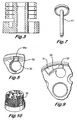
- Figure 7 is a perspective view of an axial gripping shaft; and
- Figure 8 (plan), Figure 9 (enlarged fragment from Figure 8), and Figure 10 (perspective) show an alternative disc holder.
- Referring to Figure 1, a
hub 11 is clamped by threebolts 12 to alower collet 13 which is held within arotary carrier 14 having rotary driving means at its base end (not shown). - The disc holder shown is arranged to carry a stack of four
media storage discs 15 although other numbers of media discs could be carried in a similar device with the necessary and obvious changes with reference to the described arrangement. - The four
discs 15 are held in a spaced relation by fivespacer rings 16. The spacer rings andmedia discs 15 are held in position by a central axial T-section gripping shaft 17. The T-section shaft 17 is shown in perspective in Figure 7. - The
disc holder hub 11 in this embodiment is so dimensioned thatmedia discs 15 can be slipped over thehub 11 with only a relatively small resistance. This is because the external diameter of the disc carrying portion of thehub 11 is generally slightly smaller than the internal diameter of the bore of the disc to be carried. - However as most clearly seen in Figures 2, 4 and 5, a plurality of radial
centring arms 18 are provided which contact the bore of a carried disc. In this case there is a separate set of threearms 18 acting on each disc. The threearms 18 in each set are equi-spaced, arcuate in shape, and have relatively thin portions so as to provide resilient movability in a radial direction. Thearms 18 are disposed in, and moveable in, planes which are substantially perpendicular to the axis of thehub 11. - The three centring
arms 18 are machined so that, in their rest positions, an outerperipheral surface contour 18a of eacharm 18 projects slightly beyond the external diameter of the remainder of the disc carrying portion of thehub 11. The amount which eachouter surface 18a projects is too small to be clearly seen in the drawings. The exact extent of projection will depend on design choice but typically may be in the region of a few thousandths of an inch (hundredths of a mm). Thearms 18 deflect slightly as discs are passed over them and as each disc is located into its final position. - To ensure that the
arms 18 can be machined so as to project by the correct amount, grub screw holes 19 (see Figure 4) are provided so that the machinedarms 18 can be positioned radially inwards via grub screws thus allowing machining of the external diameter of the hub. - In an alternative disc holder shown in Figures 8, 9 and 10 different shaped centring
arms 30 are provided. The ends of these centringarms 30 are again arranged to be proud of the periphery of thehub 11 so that they are in a resilient gripping relationship with carried media discs. A generallytrapezoidal hole 31 is provided axially in the region of each arm to aid in loading and removal of the discs. Theaxial holes 31 provided in the region outside thearcuate arms 30 enable insertion of a tool for forcing thearms 30 radially inwards to facilitate loading and removal of the discs. The tool has projections which are locatable in each trapezoidal hole. The tool is rotated into position relative to thehub 11 to move the ends of thearms 30 to retracted positions. The profile of each arm in the region of the trapezoidal holes, is such as to present a ramp to the respective projection of the tool during rotation to withdraw the arms. - Further, in this device the outer end of each
arm 30 has slight bevel edges 32 to aid the internal bore of each disc in sliding over the ends of thearms 30 during loading and unloading. - In both holders described above the
hub 11, and in particular, the disc carrying portion of thehub 11, is machined from a single piece of material. This ensures that the characteristics of eachresilient arm arms hub 11 and bore of the disc due to manufacturing tolerances of the disc. In some cases centring may be improved by a factor of 50 to 100 times that of the disc bore tolerance. - In certain cases it may be found necessary or convenient to use two or more pieces of material in manufacture of the hub. However, in such cases, the arms may still be formed of material integral or monolithic with the hub. That is to say to give the advantages of ease of manufacture and consistency of characteristics between the arms, each arm may be integral with a respective part of the hub. In one example, a set of arms associated with one disc may be integral with a first part of the hub and another set of arms associated with another disc may be integral with a second part of the hub.
- At least the critical parts of the hub may be machined by electrical discharge machining to obtain the desired accuracy. The
hub 11 is typically of steel and thespacers 16 of Aluminium. - In both holders described above, although the
arms radial arms axial shaft 17 holding the stack together is clamped in position by spring loaded balls 21 (see Figure 6) which are kept in position by bolts 22 (see Figure 1) holding the balls within a spring loadedcage 23 which permits the balls to rotate. Theballs 21, as well as bearing against theshaft 17, also bear against a bearingsurface 24 which is inwardly inclined with respect to the central axis of the device. Aspring 25 holds the balls resiliently in this position by providing an axial loading on thecage 23. - This arrangement allows the
axial shaft 17 to be inserted into the device and the balls to rotate during this action. However, while the balls can rotate together with the motion of inserting theaxial shaft 17, any movement to remove theshaft 17 causes the balls to ride up theinclined surfaces 24 and tighten their grip on the shaft. Thus, the balls provide a one-way gripping action on theshaft 17. After use the balls can be released by use of a tool to compress thespring 25 and release the loading on thecage 23. - In use, a stack of
discs 15 andspacers 16 are loaded onto thehub 11 and therespective arms discs 15. Theaxial shaft 17 is then inserted and pushed fully down to provide axial clamping on thediscs 15, via thespacers 16, to ensure that thediscs 16 andhub 11 will rotate as a whole. - After the discs have been processed, for example by writing tracks thereon, the
axial shaft 17 is released and removed and thediscs 15 removed for assembly into a final disc drive unit. - Although particularly suitable for use in the manufacture of hard disc drive units, carriers like or similar to those described above may be used in other circumstances such as writing and/or reading such media discs or any other media discs in manufacture, testing or final use.
Claims (15)
- A disc holder for holding at least one media storage disc (15) during rotation, said holder comprising a central hub (11) arranged for rotation about a central axis and comprising means for carrying at least one media disc (15), wherein said hub (11) comprises resilient centring means characterised in that resilient centring means comprises at least one plurality of resilient arms (18, 30) arranged to provide an outwardly directed centring force on an internal bore of a carried disc (15) in order to centre the carried disc (15) about the axis of rotation of the hub (11), the plurality of arms (18, 30) being disposed in, and movable in, a plane which is substantially perpendicular to the axis of rotation of the hub (11).
- A disc holder according to claim 1 which is arranged for holding a stack of axially spaced media storage discs (15) wherein the resilient centring means comprises a respective plurality of resilient arms (18, 30) for centring each storage disc (15).
- A disc holder according to claim 1 or claim 2 in which the or each storage disc (15) is removably mountable on the hub (11).
- A disc holder according to any preceding claim in which the resilient centring means comprises at least three resilient centring arms (18, 30) acting on the or each disc (15).
- A disc holder according to any preceding claim in which the arms (18, 30) are arranged in a configuration which provides equalised centring forces around the rotational axis.
- A disc holder according to any preceding claim in which the arms (18, 30) are in the form of arcuate leaf springs.
- A disc holder according to any preceding claim in which the arms are each formed of material integral with the hub (11).
- A disc holder according to claim 7 in which the hub (11) including all arms is formed of a single piece of material.
- A disc holder according to any preceding claim in which each arm (18, 30) is located at the edge of a generally circular aperture.
- A disc holder according to any preceding claim which comprises axial gripping means to ensure that the or each carried disc (15) and the hub (11) rotate as a whole.
- A disc holder according to claim 10 in which the axial gripping means has a central shaft (17) which is held in position by at least two clamps (21) which are spring loaded against inclined surfaces.
- A disc holder according to claim 11 in which the surfaces are inclined with respect to the axial direction so that pulling the shaft (17) in one direction forces the clamps up the inclined surfaces and thereby tightens the clamping force on the central shaft (17).
- A disc holder according to claim 12 in which the clamps (21) are of arcuate section, for example balls (21), which can rotate so as to ride up the respective inclined surfaces to increase the clamping force.
- A disc holder according to any one of claims 11 to 13 in which the shaft (17) comprises an enlarged end for contacting with and retaining a stack of axially spaced media storage discs held by the holder.
- A disc holder according to claim 14 in which the shaft (17) is generally T-section.
Priority Applications (1)
| Application Number | Priority Date | Filing Date | Title |
|---|---|---|---|
| EP06075003A EP1655729B1 (en) | 2000-05-15 | 2001-05-10 | Data storage disc carrier |
Applications Claiming Priority (3)
| Application Number | Priority Date | Filing Date | Title |
|---|---|---|---|
| GBGB0011714.3A GB0011714D0 (en) | 2000-05-15 | 2000-05-15 | Data storage disc carrier |
| GB0011714 | 2000-05-15 | ||
| PCT/GB2001/002055 WO2001088912A1 (en) | 2000-05-15 | 2001-05-10 | Data storage disc carrier |
Related Child Applications (1)
| Application Number | Title | Priority Date | Filing Date |
|---|---|---|---|
| EP06075003A Division EP1655729B1 (en) | 2000-05-15 | 2001-05-10 | Data storage disc carrier |
Publications (2)
| Publication Number | Publication Date |
|---|---|
| EP1282898A1 EP1282898A1 (en) | 2003-02-12 |
| EP1282898B1 true EP1282898B1 (en) | 2007-04-11 |
Family
ID=9891641
Family Applications (2)
| Application Number | Title | Priority Date | Filing Date |
|---|---|---|---|
| EP06075003A Expired - Lifetime EP1655729B1 (en) | 2000-05-15 | 2001-05-10 | Data storage disc carrier |
| EP01925762A Expired - Lifetime EP1282898B1 (en) | 2000-05-15 | 2001-05-10 | Data storage disc carrier |
Family Applications Before (1)
| Application Number | Title | Priority Date | Filing Date |
|---|---|---|---|
| EP06075003A Expired - Lifetime EP1655729B1 (en) | 2000-05-15 | 2001-05-10 | Data storage disc carrier |
Country Status (9)
| Country | Link |
|---|---|
| US (2) | US7134129B2 (en) |
| EP (2) | EP1655729B1 (en) |
| JP (1) | JP2003533841A (en) |
| CN (2) | CN100418147C (en) |
| AT (2) | ATE359586T1 (en) |
| AU (1) | AU2001252440A1 (en) |
| DE (2) | DE60127831D1 (en) |
| GB (1) | GB0011714D0 (en) |
| WO (1) | WO2001088912A1 (en) |
Families Citing this family (4)
| Publication number | Priority date | Publication date | Assignee | Title |
|---|---|---|---|---|
| KR100411789B1 (en) * | 2001-12-04 | 2003-12-24 | 삼성전자주식회사 | Disk chuck |
| GB0422545D0 (en) * | 2004-10-11 | 2004-11-10 | Westwind Air Bearings Ltd | Data storage disc carriers |
| KR101101516B1 (en) * | 2010-04-23 | 2012-01-04 | 삼성전기주식회사 | Disc chucking device, motor and disc drive device |
| CN114283855B (en) * | 2020-09-27 | 2024-06-07 | 上海强然数码科技有限公司 | Storage system |
Family Cites Families (21)
| Publication number | Priority date | Publication date | Assignee | Title |
|---|---|---|---|---|
| US4166622A (en) * | 1978-02-13 | 1979-09-04 | Rager Edgar A | Centering collar for a disk hub |
| US4347599A (en) * | 1980-10-20 | 1982-08-31 | Discovision Associates | Spindle clamp assembly for a video recorder-playback machine |
| US4472713A (en) | 1981-11-06 | 1984-09-18 | Itek Corporation | Optical encoder with integral flexible coupler |
| JPS59165282A (en) * | 1983-03-11 | 1984-09-18 | Hitachi Ltd | Magnetic disc fixing mechanism |
| US4881745A (en) * | 1988-04-25 | 1989-11-21 | Peters Roger D | Mechanical plate clamp |
| DE3816975A1 (en) * | 1988-05-18 | 1989-11-30 | Siemens Ag | DISK DRIVE OF A DATA STORAGE DEVICE |
| JPH02199635A (en) | 1989-01-27 | 1990-08-08 | Hitachi Ltd | Information recording disc, its manufacturing method, and recording device |
| US5056082A (en) * | 1989-06-12 | 1991-10-08 | Ekhoff Donald L | Apparatus for clamping removable disks |
| DE3919611A1 (en) | 1989-06-15 | 1990-12-20 | Wacker Chemitronic | HOLDING DEVICE FOR RECEIVING DISC-SHAPED OBJECTS, IN PARTICULAR SEMICONDUCTOR DISC, AND METHOD FOR THEIR TREATMENT |
| US5025340A (en) | 1989-10-16 | 1991-06-18 | Roger Peters | Rotary chuck for centering and retaining data discs |
| US5270999A (en) * | 1990-12-10 | 1993-12-14 | Conner Peripherals, Inc. | Apparatus and method for reducing disk distortion |
| US5243481A (en) | 1991-09-25 | 1993-09-07 | Integral Peripherals, Inc. | Clamp for information storage disk |
| JP2662339B2 (en) | 1992-03-18 | 1997-10-08 | 富士通株式会社 | Mounting structure of magnetic disk |
| WO1993026006A1 (en) * | 1992-06-08 | 1993-12-23 | Digital Equipment Corporation | Disk centering device |
| US5436775A (en) * | 1993-05-31 | 1995-07-25 | Nec Corporation | Magnetic disk device |
| US5659443A (en) * | 1995-12-01 | 1997-08-19 | International Business Machines Corporation | Split band retainer for radially clamping a disk to a hub in a disk drive |
| US5781374A (en) * | 1995-12-18 | 1998-07-14 | Seagate Technology, Inc. | Disc centering device for a disc drive |
| DE19702227A1 (en) * | 1997-01-23 | 1998-07-30 | 3R Syst Int Ab | Holding device in particular for a workpiece |
| JP3831043B2 (en) | 1997-01-24 | 2006-10-11 | 東京エレクトロン株式会社 | Rotation processing device |
| TW491998B (en) * | 2000-03-01 | 2002-06-21 | Ind Tech Res Inst | Thin type disc self-clamping device |
| US6484407B2 (en) | 2001-03-15 | 2002-11-26 | Puzant Khatchadourian | Food cutting utensil |
-
2000
- 2000-05-15 GB GBGB0011714.3A patent/GB0011714D0/en not_active Ceased
-
2001
- 2001-05-10 DE DE60127831T patent/DE60127831D1/en not_active Expired - Lifetime
- 2001-05-10 CN CNB2004100323589A patent/CN100418147C/en not_active Expired - Fee Related
- 2001-05-10 US US10/275,919 patent/US7134129B2/en not_active Expired - Fee Related
- 2001-05-10 AU AU2001252440A patent/AU2001252440A1/en not_active Abandoned
- 2001-05-10 CN CNB018095550A patent/CN1231904C/en not_active Expired - Fee Related
- 2001-05-10 AT AT01925762T patent/ATE359586T1/en not_active IP Right Cessation
- 2001-05-10 DE DE60131035T patent/DE60131035T2/en not_active Expired - Fee Related
- 2001-05-10 EP EP06075003A patent/EP1655729B1/en not_active Expired - Lifetime
- 2001-05-10 EP EP01925762A patent/EP1282898B1/en not_active Expired - Lifetime
- 2001-05-10 AT AT06075003T patent/ATE376242T1/en not_active IP Right Cessation
- 2001-05-10 WO PCT/GB2001/002055 patent/WO2001088912A1/en not_active Ceased
- 2001-05-10 JP JP2001584423A patent/JP2003533841A/en active Pending
-
2006
- 2006-09-12 US US11/530,951 patent/US7367038B2/en not_active Expired - Fee Related
Also Published As
| Publication number | Publication date |
|---|---|
| US20070011695A1 (en) | 2007-01-11 |
| ATE376242T1 (en) | 2007-11-15 |
| CN1231904C (en) | 2005-12-14 |
| JP2003533841A (en) | 2003-11-11 |
| EP1655729A1 (en) | 2006-05-10 |
| CN1551174A (en) | 2004-12-01 |
| CN1429389A (en) | 2003-07-09 |
| US7367038B2 (en) | 2008-04-29 |
| EP1655729B1 (en) | 2007-10-17 |
| DE60131035D1 (en) | 2007-11-29 |
| US20030156530A1 (en) | 2003-08-21 |
| EP1282898A1 (en) | 2003-02-12 |
| WO2001088912A1 (en) | 2001-11-22 |
| DE60131035T2 (en) | 2008-07-24 |
| DE60127831D1 (en) | 2007-05-24 |
| US7134129B2 (en) | 2006-11-07 |
| ATE359586T1 (en) | 2007-05-15 |
| GB0011714D0 (en) | 2000-07-05 |
| AU2001252440A1 (en) | 2001-11-26 |
| CN100418147C (en) | 2008-09-10 |
Similar Documents
| Publication | Publication Date | Title |
|---|---|---|
| US4091454A (en) | Self-centering disk having an eccentric elliptical-shaped center locating hole | |
| EP0522717B1 (en) | Pivot mechanism for a rotary head actuator | |
| US5666243A (en) | Spring loaded stacked actuator assembly | |
| US5590004A (en) | Resilient clamp and compliant element data disk support system | |
| EP0728356B1 (en) | High wall disk clamp design | |
| JPH0887841A (en) | Actuator arm assembly and disk drive system | |
| CN1127401A (en) | Integral hub and disk clamp for a disk drive storage device | |
| US5486961A (en) | Resilient compliant clamp for data storage disk drives | |
| EP0030754A1 (en) | Centering element and drive unit for interchangeable information discs in a system for writing or reading information | |
| EP1655729B1 (en) | Data storage disc carrier | |
| US20080253019A1 (en) | Magnetic medium stack assembly for a data storage and retrieval system | |
| EP0160494A1 (en) | Floppy disc drives | |
| US5715114A (en) | Multi-piece hub for supporting recording disks in a hard disk drive | |
| US5828518A (en) | Disc centering sleeve for a disc drive | |
| US4503530A (en) | Disk hub spindle system | |
| US7016147B2 (en) | Disk clamp balancing in a disc stack assembly | |
| EP0193699A1 (en) | Spindle shafts and method of attaching same to bearing assemblies | |
| JP4117104B2 (en) | Disk medium incorporating method and apparatus | |
| US20020181150A1 (en) | Releasable disc clamping assembly | |
| US5465477A (en) | Method of assembling a head arm stack for a magnetic disk drive | |
| US5410794A (en) | Caddy and carrier tool for assembling a head arm stack | |
| US6307706B1 (en) | Disc arrangement on a hydrodynamic motor | |
| WO1996016407A1 (en) | Guided disk handling system | |
| JPS5936373A (en) | Disc-shaped recording medium playback device | |
| WO1998053453A1 (en) | Method and apparatus for clamping removable data storage disks in a disk drive |
Legal Events
| Date | Code | Title | Description |
|---|---|---|---|
| PUAI | Public reference made under article 153(3) epc to a published international application that has entered the european phase |
Free format text: ORIGINAL CODE: 0009012 |
|
| 17P | Request for examination filed |
Effective date: 20021125 |
|
| AK | Designated contracting states |
Designated state(s): AT BE CH CY DE DK ES FI FR GB GR IE IT LI LU MC NL PT SE TR |
|
| AX | Request for extension of the european patent |
Extension state: AL LT LV MK RO SI |
|
| GRAP | Despatch of communication of intention to grant a patent |
Free format text: ORIGINAL CODE: EPIDOSNIGR1 |
|
| GRAL | Information related to payment of fee for publishing/printing deleted |
Free format text: ORIGINAL CODE: EPIDOSDIGR3 |
|
| GRAS | Grant fee paid |
Free format text: ORIGINAL CODE: EPIDOSNIGR3 |
|
| RAP1 | Party data changed (applicant data changed or rights of an application transferred) |
Owner name: GSI GROUP LIMITED |
|
| GRAA | (expected) grant |
Free format text: ORIGINAL CODE: 0009210 |
|
| AK | Designated contracting states |
Kind code of ref document: B1 Designated state(s): AT BE CH CY DE DK ES FI FR GB GR IE IT LI LU MC NL PT SE TR |
|
| PG25 | Lapsed in a contracting state [announced via postgrant information from national office to epo] |
Ref country code: FI Free format text: LAPSE BECAUSE OF FAILURE TO SUBMIT A TRANSLATION OF THE DESCRIPTION OR TO PAY THE FEE WITHIN THE PRESCRIBED TIME-LIMIT Effective date: 20070411 Ref country code: LI Free format text: LAPSE BECAUSE OF FAILURE TO SUBMIT A TRANSLATION OF THE DESCRIPTION OR TO PAY THE FEE WITHIN THE PRESCRIBED TIME-LIMIT Effective date: 20070411 Ref country code: CH Free format text: LAPSE BECAUSE OF FAILURE TO SUBMIT A TRANSLATION OF THE DESCRIPTION OR TO PAY THE FEE WITHIN THE PRESCRIBED TIME-LIMIT Effective date: 20070411 |
|
| REG | Reference to a national code |
Ref country code: GB Ref legal event code: FG4D |
|
| REG | Reference to a national code |
Ref country code: CH Ref legal event code: EP |
|
| REG | Reference to a national code |
Ref country code: IE Ref legal event code: FG4D |
|
| REF | Corresponds to: |
Ref document number: 60127831 Country of ref document: DE Date of ref document: 20070524 Kind code of ref document: P |
|
| PG25 | Lapsed in a contracting state [announced via postgrant information from national office to epo] |
Ref country code: SE Free format text: LAPSE BECAUSE OF FAILURE TO SUBMIT A TRANSLATION OF THE DESCRIPTION OR TO PAY THE FEE WITHIN THE PRESCRIBED TIME-LIMIT Effective date: 20070711 |
|
| PG25 | Lapsed in a contracting state [announced via postgrant information from national office to epo] |
Ref country code: ES Free format text: LAPSE BECAUSE OF FAILURE TO SUBMIT A TRANSLATION OF THE DESCRIPTION OR TO PAY THE FEE WITHIN THE PRESCRIBED TIME-LIMIT Effective date: 20070722 |
|
| PG25 | Lapsed in a contracting state [announced via postgrant information from national office to epo] |
Ref country code: PT Free format text: LAPSE BECAUSE OF FAILURE TO SUBMIT A TRANSLATION OF THE DESCRIPTION OR TO PAY THE FEE WITHIN THE PRESCRIBED TIME-LIMIT Effective date: 20070911 |
|
| NLV1 | Nl: lapsed or annulled due to failure to fulfill the requirements of art. 29p and 29m of the patents act | ||
| REG | Reference to a national code |
Ref country code: CH Ref legal event code: PL |
|
| PG25 | Lapsed in a contracting state [announced via postgrant information from national office to epo] |
Ref country code: AT Free format text: LAPSE BECAUSE OF FAILURE TO SUBMIT A TRANSLATION OF THE DESCRIPTION OR TO PAY THE FEE WITHIN THE PRESCRIBED TIME-LIMIT Effective date: 20070411 |
|
| EN | Fr: translation not filed | ||
| PG25 | Lapsed in a contracting state [announced via postgrant information from national office to epo] |
Ref country code: BE Free format text: LAPSE BECAUSE OF FAILURE TO SUBMIT A TRANSLATION OF THE DESCRIPTION OR TO PAY THE FEE WITHIN THE PRESCRIBED TIME-LIMIT Effective date: 20070411 |
|
| PG25 | Lapsed in a contracting state [announced via postgrant information from national office to epo] |
Ref country code: DK Free format text: LAPSE BECAUSE OF FAILURE TO SUBMIT A TRANSLATION OF THE DESCRIPTION OR TO PAY THE FEE WITHIN THE PRESCRIBED TIME-LIMIT Effective date: 20070411 Ref country code: DE Free format text: LAPSE BECAUSE OF FAILURE TO SUBMIT A TRANSLATION OF THE DESCRIPTION OR TO PAY THE FEE WITHIN THE PRESCRIBED TIME-LIMIT Effective date: 20070412 Ref country code: MC Free format text: LAPSE BECAUSE OF NON-PAYMENT OF DUE FEES Effective date: 20070531 Ref country code: NL Free format text: LAPSE BECAUSE OF FAILURE TO SUBMIT A TRANSLATION OF THE DESCRIPTION OR TO PAY THE FEE WITHIN THE PRESCRIBED TIME-LIMIT Effective date: 20070411 |
|
| PLBE | No opposition filed within time limit |
Free format text: ORIGINAL CODE: 0009261 |
|
| STAA | Information on the status of an ep patent application or granted ep patent |
Free format text: STATUS: NO OPPOSITION FILED WITHIN TIME LIMIT |
|
| 26N | No opposition filed |
Effective date: 20080114 |
|
| PG25 | Lapsed in a contracting state [announced via postgrant information from national office to epo] |
Ref country code: GR Free format text: LAPSE BECAUSE OF FAILURE TO SUBMIT A TRANSLATION OF THE DESCRIPTION OR TO PAY THE FEE WITHIN THE PRESCRIBED TIME-LIMIT Effective date: 20070712 Ref country code: IT Free format text: LAPSE BECAUSE OF FAILURE TO SUBMIT A TRANSLATION OF THE DESCRIPTION OR TO PAY THE FEE WITHIN THE PRESCRIBED TIME-LIMIT Effective date: 20070411 Ref country code: FR Free format text: LAPSE BECAUSE OF FAILURE TO SUBMIT A TRANSLATION OF THE DESCRIPTION OR TO PAY THE FEE WITHIN THE PRESCRIBED TIME-LIMIT Effective date: 20071207 |
|
| PG25 | Lapsed in a contracting state [announced via postgrant information from national office to epo] |
Ref country code: IE Free format text: LAPSE BECAUSE OF NON-PAYMENT OF DUE FEES Effective date: 20070510 |
|
| PG25 | Lapsed in a contracting state [announced via postgrant information from national office to epo] |
Ref country code: FR Free format text: LAPSE BECAUSE OF FAILURE TO SUBMIT A TRANSLATION OF THE DESCRIPTION OR TO PAY THE FEE WITHIN THE PRESCRIBED TIME-LIMIT Effective date: 20070411 |
|
| PG25 | Lapsed in a contracting state [announced via postgrant information from national office to epo] |
Ref country code: CY Free format text: LAPSE BECAUSE OF FAILURE TO SUBMIT A TRANSLATION OF THE DESCRIPTION OR TO PAY THE FEE WITHIN THE PRESCRIBED TIME-LIMIT Effective date: 20070411 |
|
| PG25 | Lapsed in a contracting state [announced via postgrant information from national office to epo] |
Ref country code: LU Free format text: LAPSE BECAUSE OF NON-PAYMENT OF DUE FEES Effective date: 20070510 |
|
| PG25 | Lapsed in a contracting state [announced via postgrant information from national office to epo] |
Ref country code: TR Free format text: LAPSE BECAUSE OF FAILURE TO SUBMIT A TRANSLATION OF THE DESCRIPTION OR TO PAY THE FEE WITHIN THE PRESCRIBED TIME-LIMIT Effective date: 20070411 |
|
| PGFP | Annual fee paid to national office [announced via postgrant information from national office to epo] |
Ref country code: GB Payment date: 20150528 Year of fee payment: 15 |
|
| GBPC | Gb: european patent ceased through non-payment of renewal fee |
Effective date: 20160510 |
|
| PG25 | Lapsed in a contracting state [announced via postgrant information from national office to epo] |
Ref country code: GB Free format text: LAPSE BECAUSE OF NON-PAYMENT OF DUE FEES Effective date: 20160510 |