EP1282030A1 - Computer system and computer-readable recording medium - Google Patents
Computer system and computer-readable recording medium Download PDFInfo
- Publication number
- EP1282030A1 EP1282030A1 EP01926134A EP01926134A EP1282030A1 EP 1282030 A1 EP1282030 A1 EP 1282030A1 EP 01926134 A EP01926134 A EP 01926134A EP 01926134 A EP01926134 A EP 01926134A EP 1282030 A1 EP1282030 A1 EP 1282030A1
- Authority
- EP
- European Patent Office
- Prior art keywords
- time
- processing unit
- central processing
- out interruption
- interruption
- Prior art date
- Legal status (The legal status is an assumption and is not a legal conclusion. Google has not performed a legal analysis and makes no representation as to the accuracy of the status listed.)
- Withdrawn
Links
Images




Classifications
-
- G—PHYSICS
- G06—COMPUTING OR CALCULATING; COUNTING
- G06F—ELECTRIC DIGITAL DATA PROCESSING
- G06F1/00—Details not covered by groups G06F3/00 - G06F13/00 and G06F21/00
- G06F1/26—Power supply means, e.g. regulation thereof
- G06F1/32—Means for saving power
- G06F1/3203—Power management, i.e. event-based initiation of a power-saving mode
- G06F1/3206—Monitoring of events, devices or parameters that trigger a change in power modality
- G06F1/3228—Monitoring task completion, e.g. by use of idle timers, stop commands or wait commands
-
- G—PHYSICS
- G06—COMPUTING OR CALCULATING; COUNTING
- G06F—ELECTRIC DIGITAL DATA PROCESSING
- G06F1/00—Details not covered by groups G06F3/00 - G06F13/00 and G06F21/00
- G06F1/26—Power supply means, e.g. regulation thereof
- G06F1/32—Means for saving power
- G06F1/3203—Power management, i.e. event-based initiation of a power-saving mode
Definitions
- the present invention relates to a computer system provided with a central processing unit having, in addition to a normal mode, a plurality of power saving modes characterized by difference levels of power consumption and to a computer readable recording medium readable by such a system. More particularly, the invention relates to a computer system capable of effectively reducing power consumption while an application is being executed, by appropriately switching between the plurality of power saving modes of the central processing unit while appropriately executing jobs based on time-out interruptions.
- a computer system provided with a function of reducing power consumption of a central processing unit is disclosed, for example, in Japanese Laid-Open Patent Application No. 11-184550.
- a computer system using a difference timer is also proposed elsewhere.
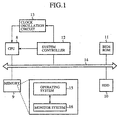
- Fig. 1 shows a construction of a related-art computer system disclosed in Japanese Laid-Open Patent Application No. 11-184550.
- the system comprises a central processing unit (CPU) 8, a memory 9, a hard disk drive (HDD) 10, a basic input and output system read-only memory (BIOSROM) 11, a system controller 12, a clock oscillation circuit 13, a system bus 14, an operating system program 14, and a monitor system program 16.
- CPU central processing unit
- HDD hard disk drive
- BIOSROM basic input and output system read-only memory
- the central processing unit 8 performs predetermined processes in accordance with the operating system program stored in the memory 9.
- the central processing unit 8 notifies the system controller 12 of the CPU usage rate.
- the system controller 12 controls intervals between timer interruptions presented to the central processing unit 8 and an oscillation frequency of the clock oscillation circuit 13. More specifically, as the idle time becomes extended and the usage rate becomes low, the intervals between timer interruptions are extended and the oscillation frequency is lowered, thereby reducing the power consumption by the central processing unit 8.
- the aforementioned system using a difference timer sets, in a timer means, a difference time indicating a period of time that elapses since the immediately preceding time-out interruption.
- the operation of the central processing unit is switched between a power saving mode and a normal mode, based on a time-out interruption of the timer means.
- a minimum interval between interruptions i.e. interruption interval at an initial state
- interruption interval at an initial state should be set so that it is smaller than the smallest transition interval between two states occurring in a system in which the technology of the Laid-Open Application is applied, in order to properly differentiate between two states that occur in succession.
- the central processing unit 8 is required to return to its operation at the small interval to perform an interruption process.
- the processing speed of the central processing unit 8 drops in any substantial manner.
- a considerable reduction in power consumption cannot be hoped for by switching to the power saving mode.
- the central processing unit is expected to perform an interruption process by returning to operation at the minimum interval defined by the system.
- the processing speed of the central processing unit 8 drops in any substantial manner.
- An appreciable reduction in power consumption cannot be hoped for by switching to the power saving mode.
- the present invention has been developed in view of the aforementioned problems and has an objective of providing a computer system provided with a central processing unit having, in addition to a normal mode, a plurality of power saving modes with difference power consumption levels, the computer system being suitably adapted for a battery-driven operation by providing the capability of effectively reducing power consumption of the central processing unit while an application is being executed, by switching between the plurality of power saving modes and executing jobs appropriately based on time-out interruptions.
- Another object is to provide a recording medium readable by such a system.
- the present invention provides a computer system comprising: a central processing unit provided, in addition to a normal mode, with a plurality of power saving modes characterized by respective power consumption levels, and sequentially executing a plurality of jobs generating associated time-out interruption requests; storage means storing a return time table mapping the plurality of power saving modes of the central processing unit into respective return time required for the central processing unit to return from the corresponding power saving mode to the normal mode; list updating means updating a time-out list, chronologically listing the time-out interruption requests, based on the time-out interruption requests from the plurality of jobs executed by the central processing unit; timer means outputting time-out interruptions to the central processing unit when the time-out time listed in the time-out list elapses; setting means setting a next time-out time in the timer means whenever a time-out interruption occurs in accordance with the order listed in the time-out list; transition mode selection means referring to the return time table when the central processing unit is put in an idle state, and selecting, as a transition mode,
- the central processing unit is operated in a power-saving mode having the longest return time of a plurality of power-saving modes provided in the central processing unit, the maximum of the return time being defined by the interval between time-out interruptions.
- the power-saving mode having a return time longer than that of the power-saving mode in which the processing unit returns to a normal mode before the shortest interruption interval occurring in the system expires so as to perform an interruption process. Accordingly, power consumption in the corresponding period is reduced. Further, since the time-out time of the jobs is managed based on the time-out list such that the time-out interruption occurs at the designated time, unnecessary interruptions are prevented from occurring in the period in which the processing unit is set to the power-saving mode, providing further reduction in power consumption.
- the power-saving mode is selected such that the central processing unit is returned to a normal mode before the next interruption occurs so that the central processing unit is capable of executing the process for the preceding interruption prior to the occurrence of the next interruption.
- two successive time-out interruptions are appropriately processed as separate time-out interruptions.
- the computer system is capable of effectively reducing power consumption while an application is being executed, by appropriately switching between the plurality of power saving modes of the central processing unit while appropriately executing jobs based on time-out interruptions.
- the present invention also provides a computer system comprising: transition mode selection means referring to the return time table when the central processing unit is put in an idle state, and selecting, as a transition mode, a power saving mode having the longest return time from a group of one or a plurality of power saving modes having a return time shorter than a period of time that remains until the subsequent time-out interruption; and remaining time setting means setting a period of time that remains after subtracting the return time of the transition mode from the remaining time.
- the central processing unit is capable of executing the job at a desired speed at the requested timing. Extension of time required for completion of the job is prevented. The performance of the central processing unit is prevented from dropping.
- the list updating means may update a time-out list listing, for each job requesting a time-out interruption, a difference time from the immediately preceding time-out interruption and a permitted error time permitted for the occurrence of the time-out interruption from the listed job.
- the setting means may successively examine the listed jobs until an accumulation of the difference time is longer than the permitted error time associated with the job, so as to set an accumulated time immediately preceding the satisfaction of the above-mentioned criterion.
- the central processing unit may successively execute, at the time-out interruption, time-out interruption processes from jobs including the last examined job.
- the list updating means may update the time-out list when there is a time-out interruption request from a new job such that the new job is added to the time-out list at a proper location determined by a time-out interruption request time, and combining time-out interruptions when an error time permitted for the occurrence of the time-out interruption from the new job is longer than a difference in time between the new job and an immediately preceding time-out interruption or a difference in time between the new job and an immediately following time-out interruption, such that the immediately preceding time-out interruption or the immediately following time-out interruption is processed as a time-out interruption from the new job.
- the present invention provides a computer readable recording medium storing a program causing a computer to function as: table storage control means causing storage means to store a return time table mapping each of a plurality of power saving modes of a central processing unit into a respective return time required for the central processing unit to return to a normal mode; list updating means updating a time-out list, chronologically listing the time-out interruption requests, based on the time-out interruption requests from the plurality of jobs executed by the central processing unit; setting means setting a next time-out time in the timer means whenever a time-out interruption occurs in accordance with the order listed in the time-out list; transition mode selection means referring to the return time table when the central processing unit is put in an idle state, and selecting, as a transition mode, a power saving mode having the longest return time, from a group of one or a plurality of power saving modes having return times shorter than the time-out time set designated for the subsequent time-out interruption; and operation mode control means controlling the central processing unit to operate in the transition mode since the start
- the computer readable recording medium may store a program causing the computer to function as transition mode selection means referring to the return time table when the central processing unit is put in an idle state, and selecting, as a transition mode, a power saving mode having the longest return time from a group of one or a plurality of power saving modes having a return time shorter than a period of time that remains until the subsequent time-out interruption; and remaining time setting means setting a period of time that remains after subtracting the return time of the transition mode from the remaining time.
- Fig. 2 is a block diagram showing a hardware construction of a computer system according to a first embodiment of the present invention.
- the system comprises a central processing unit 1 provided, in addition to a normal mode, with a plurality of power saving modes characterized by respective power consumption levels and sequentially executing a program in units of jobs, a random access memory 2 in which a program execution area is set up for the central processing unit 1, a large-capacity memory 3 (storage means) such as a hard disk drive for storing a program etc., a timer (timer means) 4 outputting a time-out interruption to the central processing unit 1 when a preset period of time elapses, a recording medium 5 storing an operating system (OS) executed by the central processing unit 1, an application program (AP) executed on the OS, and various data.
- Reference numeral 6 indicates a recording medium reader for reading data from the recording medium and 7 indicates a system bus for input and output of data exchanged between the central processing unit 1, the random access memory 2, the large-
- Fig. 3 is a return time table stored in a recording medium 5 according to the first embodiment.
- the left column of the table lists power saving modes provided in the central processing unit 1 and the right column lists return time required for the power saving mode to return to the normal mode.
- the table of Fig. 3 shows that the central processing unit 1 is provided with three power saving modes a, b, c characterized by reduced power consumption, in addition to the normal mode in which the central processing unit 1 is operated at the full operating power. Units of time "0", "1" and "3" are required for the respective power saving modes to return to the normal mode. The longer the period of time required before a return, the smaller the power consumption in the power saving mode.
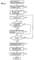
- Fig. 4 is a main flowchart showing an operation of an operating system stored in the recording medium according to the first embodiment.
- ST1 is an initial setting step wherein execution areas and the return time table are set up in the random access memory 2 in response to the start of the OS, and various environmental settings are established so that the AP is operated on the OS in response to an input of an event.
- Step ST2 is an event input determination step wherein a determination is made as to whether there is an input from a key (not shown) or the like.
- Step ST3 is for creation of a branch wherein a determination is made on the type of event so that a job adapted for the event type is executed.
- Fig. 5 is a flowchart showing a branch process performed when it is determined in step ST3 of the first embodiment that a time-out interruption is input in the form of an event.
- step ST4 is a return process step wherein the central processing unit 1 is returned from the power saving mode to the normal mode (operation mode control means).
- Step ST5 is a setting process step wherein a point of time at which the next time-out interruption is expected is set in the timer 4 (setting means).
- Step ST6 is a job execution step wherein a job that requested the time-out interruption is executed.
- Step ST7 is a time-out interruption request determination step wherein a determination is made as to whether a new time-out interruption request is generated as a result of executing the job in the execution step ST6.
- Step ST8 is a time-out list updating step wherein a new time-out interruption request is added to the time-out list (list updating means).
- Step ST9 is a cued job determination step wherein a determination is made as to whether there is a cued job to be executed subsequently.
- Step ST10 is a transition mode selection step (transition mode selection means) wherein a power saving mode, in which the central processing unit 1 should be operated in a transition time prior to the expected time-out interruption input, is selected. The selected mode is designated as a transition mode.
- Step ST11 is a transition mode setting step wherein the transition mode is set in the central processing unit 1 (operation mode control means).
- the time-out list updated in step ST8 may be a sequential list of the time-out interruption requests not yet processed, and the associated information specifying the timing of the time-out interruptions.
- the time-out list may be as shown in Fig. 6 in a computer readable format.
- the left column lists jobs that generated time-out interruption requests in the order of occurrence of the time-out interruption requests.
- the right column lists differences in time (difference time) between a time-out interruption from a job on a given row and an expected time-out interruption from a job in the next row.
- the return time table is referred to so as to select, as the transition mode, a power saving mode having the longest return time, from a group of one or a plurality of power saving modes having a return time shorter than the difference time designated for the occurrence of the next time-out interruption (the difference time in the second row).
- the central processing unit 1 When the central processing unit 1 provides an instruction for installation while the recording medium 5 is set in the recording medium reader 6, the OS and the like are read via the recording medium reader 6 and stored in the large-capacity memory 3.
- the initial setting step ST1 When the central processing unit 1 starts execution of the OS, the initial setting step ST1 is performed. The execution areas and the return time table are set up in the random access memory 2. In this state, the system waits for an input of an event (step ST2). When an event that demands reading from the return time table is input, the table is read via the recording medium reader 6 and stored in the large-capacity memory 3 (table storage control means).
- the central processing unit 1 starts the designated AP in response to the input of the event so that the jobs of the AP are sequentially executed.
- a time-out interruption request occurs, for example, in an input pending state of a job, that time-out interruption is added to the time-out list.
- the central processing unit 1 makes a transition to the power saving mode so that the system waits for an input of an event again.
- the timer 4 issues a time-out interruption to the central processing unit 1.
- the central processing unit 1 determines that a time-out interruption event is input and performs the steps of the flowchart of Fig. 5.
- the central processing unit 1 first performs the return process step ST4 so as to make a transition from the power saving mode to the normal mode.
- the difference time listed at the head of the time-out list is set in the timer 4.
- the job execution step ST6 the job at the first row is executed. The row containing the executed job is then deleted from the list.
- a determination is made in the time-out interrupt request determination step ST7 as to whether there is generated a time-out interrupt request.
- the new time-out interruption request is added to the time-out list in the time-out list updating step ST8.
- the time-out list updating step ST8 is completed, a determination is made as to whether there is a cued job to be executed subsequently. When it is determined that there is a job to be executed, steps ST6 through ST8 are repeated until the cued jobs are removed.
- the transition mode selecting step ST10 is performed so that the difference time listed in the first line (corresponding to the second line in Fig.
- the time-out list and the return time table are referred to so as to select, as the transition mode, a power saving mode (a) having the longest return time, from a group of one or a plurality of power saving modes (a) having a return time shorter than the difference time.
- the selected transition mode (a) is set in the central processing unit 1.
- the central processing unit 1 makes a transition to the selected power saving mode and waits for an input of a new event.
- the central processing unit 1 executes a predetermined AP in response to an input of an event.
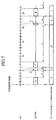
- Fig. 7 is a timing chart showing an example of operation executed according to the first embodiment by the central processing unit 1 in accordance with the time-out list of Fig. 6.
- (a) indicates a time line extending from a current time at "0";
- (b) indicates a chart illustrating operating statuses of the central processing unit 1; and
- (c) indicates a chart indicating a time-out time set in the timer 4.
- Boxes in the chart (b) in which capital letters are entered indicate duration in which the jobs A, B, ..., E of Fig. 6 are being executed.
- Two-way arrows to which lower-case letters are attached indicate that the corresponding one of the power saving modes a, b, c of Fig. 3 is being set.
- a time out counting in the timer proceeds based on the numeral entered in the boxes. Upward arrows above the borders between the boxes indicate that a time-out interruption occurs.
- the central processing unit 1 of the computer system executes jobs in the time-out list in the listed order, in accordance with time-out interruption requests from the timer 4 at intervals defined by the difference times.
- the central processing unit 1 sets a new time-out time in the timer 4 whenever a time-out interruption is input.
- the power saving mode having the longest return time is selected from a group of power saving modes having a return time shorter than the difference time designated for the next time-out interruption so that the system waits for the next time-out interruption.
- the central processing unit returns from the power saving mode to the normal mode so as to execute the predetermined job.
- an appropriate one of a plurality of power saving modes a, b, c prepared for the central processing unit 1 is selected such that the selection is not restricted by the shortest interruption interval occurring in the computer system.
- the difference time designated for a time-out interruption from a job is managed based on a time-out list. It is thus known that time-out interruptions are timed to occur as listed in the time-out list. Undesired interruptions are prevented from occurring during the power saving mode so that the power consumption is reduced more effectively.
- the power saving mode is selected to ensure that the central processing unit 1 returns to the normal mode before the occurrence of the next time-out interruption so as to be capable of starting the process responsive to the interruption. Therefore, failure to properly respond to a time-out interruption by returning to the normal mode too late is prevented. Two successive time-out interruptions are properly processed as separate interruptions.
- the system according to the first embodiment is capable of effectively reducing power consumption of the central processing unit 1 while an application is being executed, by appropriately executing jobs based on time-out interruptions.
- Such a system is suitably used in a battery-driven condition.
- Fig. 8 is a flowchart showing a branch process performed when it is determined in step ST3 of the second embodiment that a time-out interruption is input in the form of an event.
- step ST12 is a transition mode selection step (transition mode selection means) wherein the return time table and the timer 4 are referred to so as to select, of those power saving modes characterized by a return time shorter than the time that remains until the next time-out interruption, a power saving mode characterized by the longest return time.
- Step ST13 is a remaining time setting step (remaining time setting means) wherein a period of time determined by subtracting the return time of the transition mode from the remaining time is set in the timer 4.
- the system construction and steps executed by the OS are the same as those in the first embodiment so that the description thereof is omitted.
- the return time table and the timer 4 are referred to in a transition mode selection step ST12 so as to select, of those power saving modes characterized by a return time shorter than the time that remains until the next time-out interruption, a power saving mode characterized by the longest return time.
- a period of time determined by subtracting the return time of the transition mode from the remaining time is set in the timer 4.
- the selected transition mode is set in the central processing unit 1 so that the central processing unit 1 is returned to the power saving mode to wait for a new event.
- Fig. 9 is a timing chart showing an example of operation executed according to the second embodiment by the central processing unit 1 in accordance with the time-out list of Fig. 6.
- the legends entered are the same as those of Fig. 7 so that the description thereof is omitted.
- the central processing unit 1 once in an idle state, switches to a power saving mode characterized by a return time shorter than a remaining period of time available at the start of the idle state.
- the value set in the timer is changed to a value obtained by subtraction of the return time of the power saving mode from the remaining period of time.
- the system according to the second embodiment is capable of effectively reducing power consumption while an application is being executed by appropriately executing jobs based on time-out interruptions. Moreover, since a time-out interruption is timed to occur earlier than scheduled point of time specified in the time-out list by selecting the power saving mode appropriately, the period of time by which the interruption is advanced being equal to the return time of the selected power saving mode. Accordingly, at a scheduled interruption time requested by the job, the central processing unit 1 is already in the normal mode for immediate processing of the job. It is thus ensured that execution of the job is started at the same point of time as when the switching to the power saving mode did not occur. Therefore, the period of time that elapses before the completion of the job is prevented from becoming extended and the processing performance of the central processing unit 1 is prevented from dropping.
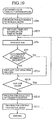
- Fig. 10 is a flowchart showing a branch process performed when it is determined in step ST3 of the third embodiment for creation of a branch that a time-out interruption is input in the form of an event.
- step ST14 is a time-out list updating step (list updating means) wherein a time-out list listing, for each job generating a time-out interruption, a time difference (difference time) from an immediately preceding time-out interruption and a permitted error time defining a margin in which the time-out interruption from that job may occur.
- Step ST15 is a setting process step (setting means) wherein, if it is determined, when setting the next time-out time subsequent to a current time-out interruption, that the difference time is longer than the permitted error time, listed jobs are successively examined until an accumulation of the difference time is longer than the permitted error time associated with the job. The accumulated time immediately preceding the satisfaction of this criterion is set in the timer 4.
- Step ST16 is a cued job determination step wherein a determination is made as to whether there are any cued jobs to be executed, including the job last examined in step ST15.
- the system construction and steps executed by the OS are the same as those in the first embodiment so that the description thereof is omitted.
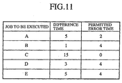
- Fig. 11 shows an example of time-out list according to the third embodiment.
- the right column lists the permitted error times, which are introduced in this embodiment and are not found in Fig. 6.
- Each row stores an error time permitted for the occurrence of the time-out interruption from the job listed in the next row.
- the central processing unit 1 determines that a time-out interruption is input in the form of an event and executes the steps of the flowchart of Fig. 10. In accordance with the illustrated flow, the central processing unit 1 executes the return process step ST4. Further, in a setting process step ST15, the central processing unit 1 sequentially examines the time-out list, starting at the first row, to compare the accumulated difference time with the permitted error time. Job-by-job search is continued until the accumulated difference time is longer than the permitted error time listed in the row. The accumulated time immediately preceding the satisfaction of this criterion is set in the timer 4.
- a job determination step ST16 a determination is made as to whether there are any cued jobs to be executed, including the job last examined in step ST15.
- One or a plurality of jobs including those jobs examined in step ST15 are executed in step ST6.
- time-out interruption request determination step ST7 Whenever the job is executed, a determination is made in the time-out interruption request determination step ST7 as to whether a time-out interruption request occurs. When it is determined that the request occurs, the new time-out interruption request is added to the time-out list in the time-out list updating step ST14. The job, the difference time and the permitted error time are entered in the time-out list.
- the other aspects of the third embodiment are the same as the corresponding aspects according to the first embodiment so that the description thereof is omitted.
- Fig. 12 is a timing chart showing an example of operation executed according to the third embodiment by a central processing unit in accordance with the time-out list of Fig. 11.
- the legends entered are the same as those of Fig. 7 so that the description thereof is omitted.
- the frequency of time-out interruptions actually occurring is reduced as compared with the first embodiment.
- Combining a plurality of idle periods into a single idle period enables selection of a power saving mode characterized by lower power consumption as compared to a case where the plurality of idle periods are separated from each other on a time line. Therefore, the low power consumption performance is improved.
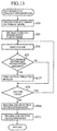
- Fig. 13 is a flowchart showing a branch process performed when it is determined in step ST3 of the fourth embodiment for creation of a branch that a time-out interruption is input in the form of an event.
- step ST17 is a time-out list updating step (list updating means) wherein, when there is a time-out interruption request from a new job, the time-out list is updated such that the new job is placed at a proper location determined by the associated time-out interruption request time.
- the time-out interruption from the immediately preceding job is also used to trigger the time-out interruption from the new job.
- the system construction and steps executed by the OS are the same as those in the first embodiment so that the description thereof is omitted.
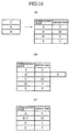
- Fig. 14 shows how a list is updated in a time-out list updating step ST17 of the fourth embodiment.
- the job C is inserted into a proper location (between B and D) based on the time-out interruption request time, as shown in (b) of Fig. 14 so that the time-out list is updated ((b) of Fig. 14).
- a comparison is made between the permitted error time "4" designated for the job c and the difference time designated for the job C at execution of the job B ("1" in the second row of the list).
- the time list is updated in the time-out list updating step ST17 such that the jobs B and C are placed in the second row, as shown in (a) of Fig. 14.
- the difference time in the combined second row is returned to the value of (c) of Fig. 14.
- the other aspects of the fourth embodiment are the same as the corresponding aspects of the first embodiment so that the description thereof is omitted. Since the jobs B and C are executed in response to the input of the time-out interruption from the job B, the central processing unit 1 operates in the same manner as illustrated in Fig. 12.
- the fourth embodiment a comparison is made between the permitted error time "4" of the newly added job C and the difference time "1" since the job B.
- the time-out list is updated such that the new job C is executed in response to the input of time-out interruption from the job B. Accordingly, the same advantage available in the third embodiment is provided without storing the permitted error time in that the frequency of time-out interruptions actually occurring is reduced. Moreover, according to the fourth embodiment, there is no need to store the permitted error time in the time-out list.
- the computer system and the computer-readable recording medium uses the central processing unit provided, in addition to a normal mode, with a plurality of power saving modes characterized by respective power consumption levels and are capable of effectively reducing power consumption of the central processing unit while an application is being executed, by appropriately switching between the plurality of power saving modes while appropriately execute jobs based on time-out interruptions.
Landscapes
- Engineering & Computer Science (AREA)
- Theoretical Computer Science (AREA)
- Physics & Mathematics (AREA)
- General Engineering & Computer Science (AREA)
- General Physics & Mathematics (AREA)
- Power Sources (AREA)
Abstract
A central processing unit is provided with a
plurality of power saving modes so that an optimum
power saving mode determined by an interval between
requested time-out interruptions is selected.
Description
The present invention relates to a computer
system provided with a central processing unit
having, in addition to a normal mode, a plurality
of power saving modes characterized by difference
levels of power consumption and to a computer
readable recording medium readable by such a system.
More particularly, the invention relates to a
computer system capable of effectively reducing
power consumption while an application is being
executed, by appropriately switching between the
plurality of power saving modes of the central
processing unit while appropriately executing jobs
based on time-out interruptions.
Sophisticated performance of application
programs recently used requires that a central
processing unit executing the program be provided
with a high-level processing performance. As a
result, many central processing units are now
operated at an increasingly high speed. The
resultant increase in power consumed in the central
processing unit now presents a serious challenge in
building a system using the central processing unit.
A computer system provided with a function of
reducing power consumption of a central processing
unit is disclosed, for example, in Japanese Laid-Open
Patent Application No. 11-184550. A computer
system using a difference timer is also proposed
elsewhere.
Fig. 1 shows a construction of a related-art
computer system disclosed in Japanese Laid-Open
Patent Application No. 11-184550. Referring to Fig.
1, the system comprises a central processing unit
(CPU) 8, a memory 9, a hard disk drive (HDD) 10, a
basic input and output system read-only memory
(BIOSROM) 11, a system controller 12, a clock
oscillation circuit 13, a system bus 14, an
operating system program 14, and a monitor system
program 16.
A description will now be given of the
operation according to the related art.
The central processing unit 8 performs
predetermined processes in accordance with the
operating system program stored in the memory 9.
When in an idle state, the central processing unit
8 notifies the system controller 12 of the CPU
usage rate. The system controller 12 controls
intervals between timer interruptions presented to
the central processing unit 8 and an oscillation
frequency of the clock oscillation circuit 13. More
specifically, as the idle time becomes extended and
the usage rate becomes low, the intervals between
timer interruptions are extended and the
oscillation frequency is lowered, thereby reducing
the power consumption by the central processing
unit 8.
The aforementioned system using a difference
timer sets, in a timer means, a difference time
indicating a period of time that elapses since the
immediately preceding time-out interruption. The
operation of the central processing unit is
switched between a power saving mode and a normal
mode, based on a time-out interruption of the timer
means.
In the related-art systems constructed as
described above, various measures directed to low
power consumption of the central processing unit 8
are employed. However, these measures fail to
provide effective and satisfactory solutions.
For example, in the system disclosed in Laid-Open
Application, a minimum interval between
interruptions (i.e. interruption interval at an
initial state) should be set so that it is smaller
than the smallest transition interval between two
states occurring in a system in which the
technology of the Laid-Open Application is applied,
in order to properly differentiate between two
states that occur in succession. As a result, even
when a situation arises in which a time interval
between different states becomes significantly
large, unnecessary interruptions occur repeatedly,
causing the central processing unit 8 to operate
each time and wasting the power accordingly.
Further, by setting a small time interval, the
central processing unit 8 is required to return to
its operation at the small interval to perform an
interruption process. Thus, it is not expected that
the processing speed of the central processing unit
8 drops in any substantial manner. A considerable
reduction in power consumption cannot be hoped for
by switching to the power saving mode. In the
aforementioned system using a difference timer, too,
the central processing unit is expected to perform
an interruption process by returning to operation
at the minimum interval defined by the system. Thus,
it is not expected that the processing speed of the
central processing unit 8 drops in any substantial
manner. An appreciable reduction in power
consumption cannot be hoped for by switching to the
power saving mode.
The present invention has been developed in
view of the aforementioned problems and has an
objective of providing a computer system provided
with a central processing unit having, in addition
to a normal mode, a plurality of power saving modes
with difference power consumption levels, the
computer system being suitably adapted for a
battery-driven operation by providing the
capability of effectively reducing power
consumption of the central processing unit while an
application is being executed, by switching between
the plurality of power saving modes and executing
jobs appropriately based on time-out interruptions.
Another object is to provide a recording medium
readable by such a system.
The present invention provides a computer
system comprising: a central processing unit
provided, in addition to a normal mode, with a
plurality of power saving modes characterized by
respective power consumption levels, and
sequentially executing a plurality of jobs
generating associated time-out interruption
requests; storage means storing a return time table
mapping the plurality of power saving modes of the
central processing unit into respective return time
required for the central processing unit to return
from the corresponding power saving mode to the
normal mode; list updating means updating a time-out
list, chronologically listing the time-out
interruption requests, based on the time-out
interruption requests from the plurality of jobs
executed by the central processing unit; timer
means outputting time-out interruptions to the
central processing unit when the time-out time
listed in the time-out list elapses; setting means
setting a next time-out time in the timer means
whenever a time-out interruption occurs in
accordance with the order listed in the time-out
list; transition mode selection means referring to
the return time table when the central processing
unit is put in an idle state, and selecting, as a
transition mode, a power saving mode having the
longest return time, from a group of one or a
plurality of power saving modes having a return
time shorter than the time-out time designated for
the subsequent time-out interruption; and operation
mode control means controlling the central
processing unit to operate in the transition mode
since the start of the idle state until an input of
the subsequent time-out interruption, and returning
the central processing unit to the normal mode when
the time-out interruption is generated.
According to this aspect of the invention, the
central processing unit is operated in a power-saving
mode having the longest return time of a
plurality of power-saving modes provided in the
central processing unit, the maximum of the return
time being defined by the interval between time-out
interruptions.
Moreover, it is possible to suitably employ
the power-saving mode having a return time longer
than that of the power-saving mode in which the
processing unit returns to a normal mode before the
shortest interruption interval occurring in the
system expires so as to perform an interruption
process. Accordingly, power consumption in the
corresponding period is reduced. Further, since the
time-out time of the jobs is managed based on the
time-out list such that the time-out interruption
occurs at the designated time, unnecessary
interruptions are prevented from occurring in the
period in which the processing unit is set to the
power-saving mode, providing further reduction in
power consumption.
The power-saving mode is selected such that
the central processing unit is returned to a normal
mode before the next interruption occurs so that
the central processing unit is capable of executing
the process for the preceding interruption prior to
the occurrence of the next interruption. Thus, two
successive time-out interruptions are appropriately
processed as separate time-out interruptions.
The computer system is capable of effectively
reducing power consumption while an application is
being executed, by appropriately switching between
the plurality of power saving modes of the central
processing unit while appropriately executing jobs
based on time-out interruptions.
The present invention also provides a computer
system comprising: transition mode selection means
referring to the return time table when the central
processing unit is put in an idle state, and
selecting, as a transition mode, a power saving
mode having the longest return time from a group of
one or a plurality of power saving modes having a
return time shorter than a period of time that
remains until the subsequent time-out interruption;
and remaining time setting means setting a period
of time that remains after subtracting the return
time of the transition mode from the remaining time.
With this, it is ensured that the processing
unit is returned to a normal mode at the time of
time-out interruption requested from the job.
Therefore, the central processing unit is capable
of executing the job at a desired speed at the
requested timing. Extension of time required for
completion of the job is prevented. The performance
of the central processing unit is prevented from
dropping.
According to the invention, the list updating
means may update a time-out list listing, for each
job requesting a time-out interruption, a
difference time from the immediately preceding
time-out interruption and a permitted error time
permitted for the occurrence of the time-out
interruption from the listed job. When it is
determined, in setting a next time-out time
subsequent to the time-out interruption, that the
difference time is longer than the permitted error
time, the setting means may successively examine
the listed jobs until an accumulation of the
difference time is longer than the permitted error
time associated with the job, so as to set an
accumulated time immediately preceding the
satisfaction of the above-mentioned criterion. The
central processing unit may successively execute,
at the time-out interruption, time-out interruption
processes from jobs including the last examined job.
With this, the frequency of time-out
interruptions is reduced. A plurality of idle
periods are combined into a single idle period,
thereby enabling selection of a power-saving mode
characterized by smaller power consumption than
when the idle periods are separate. Thus, power
consumption is further reduced.
The list updating means may update the time-out
list when there is a time-out interruption
request from a new job such that the new job is
added to the time-out list at a proper location
determined by a time-out interruption request time,
and combining time-out interruptions when an error
time permitted for the occurrence of the time-out
interruption from the new job is longer than a
difference in time between the new job and an
immediately preceding time-out interruption or a
difference in time between the new job and an
immediately following time-out interruption, such
that the immediately preceding time-out
interruption or the immediately following time-out
interruption is processed as a time-out
interruption from the new job.
With this, the frequency of time-out
interruptions is reduced. A plurality of idle
periods are combined into a single idle period,
thereby enabling selection of a power-saving mode
characterized by smaller power consumption than
when the idle periods are separate. Thus, power
consumption is further reduced.
The present invention provides a computer
readable recording medium storing a program causing
a computer to function as: table storage control
means causing storage means to store a return time
table mapping each of a plurality of power saving
modes of a central processing unit into a
respective return time required for the central
processing unit to return to a normal mode; list
updating means updating a time-out list,
chronologically listing the time-out interruption
requests, based on the time-out interruption
requests from the plurality of jobs executed by the
central processing unit; setting means setting a
next time-out time in the timer means whenever a
time-out interruption occurs in accordance with the
order listed in the time-out list; transition mode
selection means referring to the return time table
when the central processing unit is put in an idle
state, and selecting, as a transition mode, a power
saving mode having the longest return time, from a
group of one or a plurality of power saving modes
having return times shorter than the time-out time
set designated for the subsequent time-out
interruption; and operation mode control means
controlling the central processing unit to operate
in the transition mode since the start of the idle
state until an input of the subsequent time-out
interruption, and returning the central processing
unit to the normal mode when the time-out
interruption is generated.
With this, it is possible to provide the list
updating means, the setting means, the transition
mode selection means, the operation mode control
means in a computer-readable recording medium
together with the table storage control means for
causing the return time table to be stored in the
storage means.
The computer readable recording medium may
store a program causing the computer to function as
transition mode selection means referring to the
return time table when the central processing unit
is put in an idle state, and selecting, as a
transition mode, a power saving mode having the
longest return time from a group of one or a
plurality of power saving modes having a return
time shorter than a period of time that remains
until the subsequent time-out interruption; and
remaining time setting means setting a period of
time that remains after subtracting the return time
of the transition mode from the remaining time.
With this, it is possible to provide the list
updating means, the setting means, the transition
mode selection means, the operation mode control
means in a computer-readable recording medium
together with the table storage control means for
causing the return time table to be stored in the
storage means.
Hereinafter, in order to describe the
invention in further detail, the best mode of
carrying out the invention will be described with
reference to the attached drawings.
Fig. 2 is a block diagram showing a hardware
construction of a computer system according to a
first embodiment of the present invention.
Referring to Fig. 2, the system comprises a central
processing unit 1 provided, in addition to a normal
mode, with a plurality of power saving modes
characterized by respective power consumption
levels and sequentially executing a program in
units of jobs, a random access memory 2 in which a
program execution area is set up for the central
processing unit 1, a large-capacity memory 3
(storage means) such as a hard disk drive for
storing a program etc., a timer (timer means) 4
outputting a time-out interruption to the central
processing unit 1 when a preset period of time
elapses, a recording medium 5 storing an operating
system (OS) executed by the central processing unit
1, an application program (AP) executed on the OS,
and various data. Reference numeral 6 indicates a
recording medium reader for reading data from the
recording medium and 7 indicates a system bus for
input and output of data exchanged between the
central processing unit 1, the random access memory
2, the large-capacity memory 3, the timer 4 and the
recording medium reader 6.
Fig. 3 is a return time table stored in a
recording medium 5 according to the first
embodiment. The left column of the table lists
power saving modes provided in the central
processing unit 1 and the right column lists return
time required for the power saving mode to return
to the normal mode. The table of Fig. 3 shows that
the central processing unit 1 is provided with
three power saving modes a, b, c characterized by
reduced power consumption, in addition to the
normal mode in which the central processing unit 1
is operated at the full operating power. Units of
time "0", "1" and "3" are required for the
respective power saving modes to return to the
normal mode. The longer the period of time required
before a return, the smaller the power consumption
in the power saving mode.
Fig. 4 is a main flowchart showing an
operation of an operating system stored in the
recording medium according to the first embodiment.
Referring to Fig. 4, ST1 is an initial setting step
wherein execution areas and the return time table
are set up in the random access memory 2 in
response to the start of the OS, and various
environmental settings are established so that the
AP is operated on the OS in response to an input of
an event. Step ST2 is an event input determination
step wherein a determination is made as to whether
there is an input from a key (not shown) or the
like. Step ST3 is for creation of a branch wherein
a determination is made on the type of event so
that a job adapted for the event type is executed.
Fig. 5 is a flowchart showing a branch process
performed when it is determined in step ST3 of the
first embodiment that a time-out interruption is
input in the form of an event. Referring to Fig. 5,
step ST4 is a return process step wherein the
central processing unit 1 is returned from the
power saving mode to the normal mode (operation
mode control means). Step ST5 is a setting process
step wherein a point of time at which the next
time-out interruption is expected is set in the
timer 4 (setting means). Step ST6 is a job
execution step wherein a job that requested the
time-out interruption is executed. Step ST7 is a
time-out interruption request determination step
wherein a determination is made as to whether a new
time-out interruption request is generated as a
result of executing the job in the execution step
ST6. Step ST8 is a time-out list updating step
wherein a new time-out interruption request is
added to the time-out list (list updating means).
Step ST9 is a cued job determination step wherein a
determination is made as to whether there is a cued
job to be executed subsequently. Step ST10 is a
transition mode selection step (transition mode
selection means) wherein a power saving mode, in
which the central processing unit 1 should be
operated in a transition time prior to the expected
time-out interruption input, is selected. The
selected mode is designated as a transition mode.
Step ST11 is a transition mode setting step wherein
the transition mode is set in the central
processing unit 1 (operation mode control means).
The time-out list updated in step ST8 may be a
sequential list of the time-out interruption
requests not yet processed, and the associated
information specifying the timing of the time-out
interruptions. For example, the time-out list may
be as shown in Fig. 6 in a computer readable format.
Referring to Fig. 6, the left column lists jobs
that generated time-out interruption requests in
the order of occurrence of the time-out
interruption requests. The right column lists
differences in time (difference time) between a
time-out interruption from a job on a given row and
an expected time-out interruption from a job in the
next row. By using the table described above and
formatted as computer readable data, when a time-out
interruption occurs, the job located at the
head of the data is executed after an elapse of the
designated difference time. The job executed is
removed from the list so that the job to be
executed (selected) next and the associated
difference time is placed at the head of the list.
In the transition mode selection step ST10 of
the first embodiment, the return time table is
referred to so as to select, as the transition mode,
a power saving mode having the longest return time,
from a group of one or a plurality of power saving
modes having a return time shorter than the
difference time designated for the occurrence of
the next time-out interruption (the difference time
in the second row).
A description will now be given of the
operation according to the first embodiment.
When the central processing unit 1 provides an
instruction for installation while the recording
medium 5 is set in the recording medium reader 6,
the OS and the like are read via the recording
medium reader 6 and stored in the large-capacity
memory 3. When the central processing unit 1 starts
execution of the OS, the initial setting step ST1
is performed. The execution areas and the return
time table are set up in the random access memory 2.
In this state, the system waits for an input of an
event (step ST2). When an event that demands
reading from the return time table is input, the
table is read via the recording medium reader 6 and
stored in the large-capacity memory 3 (table
storage control means).
Subsequently, when a new event demanding
execution of the AP is input, the central
processing unit 1 starts the designated AP in
response to the input of the event so that the jobs
of the AP are sequentially executed. When a time-out
interruption request occurs, for example, in an
input pending state of a job, that time-out
interruption is added to the time-out list. When
the jobs, including those generated in response to
other event inputs, are removed from the cue, the
central processing unit 1 makes a transition to the
power saving mode so that the system waits for an
input of an event again.
When the preset difference time elapses, the
timer 4 issues a time-out interruption to the
central processing unit 1. The central processing
unit 1 determines that a time-out interruption
event is input and performs the steps of the
flowchart of Fig. 5. The central processing unit 1
first performs the return process step ST4 so as to
make a transition from the power saving mode to the
normal mode. In the setting process step ST5, the
difference time listed at the head of the time-out
list is set in the timer 4. In the job execution
step ST6, the job at the first row is executed. The
row containing the executed job is then deleted
from the list. A determination is made in the time-out
interrupt request determination step ST7 as to
whether there is generated a time-out interrupt
request. When it is determined that the time-out
interruption request is generated, the new time-out
interruption request is added to the time-out list
in the time-out list updating step ST8. When the
time-out list updating step ST8 is completed, a
determination is made as to whether there is a cued
job to be executed subsequently. When it is
determined that there is a job to be executed,
steps ST6 through ST8 are repeated until the cued
jobs are removed. When it is determined at the
completion of the time-out list updating step ST8
that there is no more cued jobs to be executed, the
transition mode selecting step ST10 is performed so
that the difference time listed in the first line
(corresponding to the second line in Fig. 6) of the
time-out list and the return time table are
referred to so as to select, as the transition mode,
a power saving mode (a) having the longest return
time, from a group of one or a plurality of power
saving modes (a) having a return time shorter than
the difference time. In the transition mode setting
step ST11, the selected transition mode (a) is set
in the central processing unit 1. The central
processing unit 1 makes a transition to the
selected power saving mode and waits for an input
of a new event.
By repeating the above-described steps, the
central processing unit 1 executes a predetermined
AP in response to an input of an event.
Fig. 7 is a timing chart showing an example of
operation executed according to the first
embodiment by the central processing unit 1 in
accordance with the time-out list of Fig. 6.
Referring to Fig. 7, (a) indicates a time line
extending from a current time at "0"; (b) indicates
a chart illustrating operating statuses of the
central processing unit 1; and (c) indicates a
chart indicating a time-out time set in the timer 4.
Boxes in the chart (b) in which capital letters are
entered indicate duration in which the jobs A,
B, ..., E of Fig. 6 are being executed. Two-way
arrows to which lower-case letters are attached
indicate that the corresponding one of the power
saving modes a, b, c of Fig. 3 is being set.
Referring to the chart (c), a time out counting in
the timer proceeds based on the numeral entered in
the boxes. Upward arrows above the borders between
the boxes indicate that a time-out interruption
occurs.
As shown in Fig. 7, the central processing
unit 1 of the computer system according to the
first embodiment executes jobs in the time-out list
in the listed order, in accordance with time-out
interruption requests from the timer 4 at intervals
defined by the difference times. The central
processing unit 1 sets a new time-out time in the
timer 4 whenever a time-out interruption is input.
When the job is completed and an idle time occurs
until the execution of the next job (i.e. until the
input of an event such as a next time-out
interruption), the power saving mode having the
longest return time is selected from a group of
power saving modes having a return time shorter
than the difference time designated for the next
time-out interruption so that the system waits for
the next time-out interruption. When the next time-out
interruption is input, the central processing
unit returns from the power saving mode to the
normal mode so as to execute the predetermined job.
Accordingly, an appropriate one of a plurality
of power saving modes a, b, c prepared for the
central processing unit 1 is selected such that the
selection is not restricted by the shortest
interruption interval occurring in the computer
system. Thereby, the power consumption in the idle
state of the central processing unit 1 is
effectively reduced. The difference time designated
for a time-out interruption from a job is managed
based on a time-out list. It is thus known that
time-out interruptions are timed to occur as listed
in the time-out list. Undesired interruptions are
prevented from occurring during the power saving
mode so that the power consumption is reduced more
effectively.
The power saving mode is selected to ensure
that the central processing unit 1 returns to the
normal mode before the occurrence of the next time-out
interruption so as to be capable of starting
the process responsive to the interruption.
Therefore, failure to properly respond to a time-out
interruption by returning to the normal mode
too late is prevented. Two successive time-out
interruptions are properly processed as separate
interruptions.
Accordingly, the system according to the first
embodiment is capable of effectively reducing power
consumption of the central processing unit 1 while
an application is being executed, by appropriately
executing jobs based on time-out interruptions.
Such a system is suitably used in a battery-driven
condition.
Fig. 8 is a flowchart showing a branch process
performed when it is determined in step ST3 of the
second embodiment that a time-out interruption is
input in the form of an event. Referring to Fig. 8,
step ST12 is a transition mode selection step
(transition mode selection means) wherein the
return time table and the timer 4 are referred to
so as to select, of those power saving modes
characterized by a return time shorter than the
time that remains until the next time-out
interruption, a power saving mode characterized by
the longest return time. Step ST13 is a remaining
time setting step (remaining time setting means)
wherein a period of time determined by subtracting
the return time of the transition mode from the
remaining time is set in the timer 4. The system
construction and steps executed by the OS are the
same as those in the first embodiment so that the
description thereof is omitted.
A description will now be given of the
operation according to the second embodiment.
When it is determined subsequent to the time-out
list updating step ST8 that there are no cued
jobs to be executed, the return time table and the
timer 4 are referred to in a transition mode
selection step ST12 so as to select, of those power
saving modes characterized by a return time shorter
than the time that remains until the next time-out
interruption, a power saving mode characterized by
the longest return time. In the remaining time
setting step ST13, a period of time determined by
subtracting the return time of the transition mode
from the remaining time is set in the timer 4. In
the transition mode setting step ST11, the selected
transition mode is set in the central processing
unit 1 so that the central processing unit 1 is
returned to the power saving mode to wait for a new
event. The other aspects of the operation according
to the second embodiment are the same as the
corresponding aspects of the first embodiment so
that the description thereof is omitted.
Fig. 9 is a timing chart showing an example of
operation executed according to the second
embodiment by the central processing unit 1 in
accordance with the time-out list of Fig. 6. The
legends entered are the same as those of Fig. 7 so
that the description thereof is omitted. As shown
in Fig. 7, in the computer system according to the
second embodiment, the central processing unit 1,
once in an idle state, switches to a power saving
mode characterized by a return time shorter than a
remaining period of time available at the start of
the idle state. The value set in the timer is
changed to a value obtained by subtraction of the
return time of the power saving mode from the
remaining period of time.
Accordingly, in a similar configuration as the
first embodiment, the system according to the
second embodiment is capable of effectively
reducing power consumption while an application is
being executed by appropriately executing jobs
based on time-out interruptions. Moreover, since a
time-out interruption is timed to occur earlier
than scheduled point of time specified in the time-out
list by selecting the power saving mode
appropriately, the period of time by which the
interruption is advanced being equal to the return
time of the selected power saving mode. Accordingly,
at a scheduled interruption time requested by the
job, the central processing unit 1 is already in
the normal mode for immediate processing of the job.
It is thus ensured that execution of the job is
started at the same point of time as when the
switching to the power saving mode did not occur.
Therefore, the period of time that elapses before
the completion of the job is prevented from
becoming extended and the processing performance of
the central processing unit 1 is prevented from
dropping.
Fig. 10 is a flowchart showing a branch
process performed when it is determined in step ST3
of the third embodiment for creation of a branch
that a time-out interruption is input in the form
of an event. Referring to Fig. 10, step ST14 is a
time-out list updating step (list updating means)
wherein a time-out list listing, for each job
generating a time-out interruption, a time
difference (difference time) from an immediately
preceding time-out interruption and a permitted
error time defining a margin in which the time-out
interruption from that job may occur. Step ST15 is
a setting process step (setting means) wherein, if
it is determined, when setting the next time-out
time subsequent to a current time-out interruption,
that the difference time is longer than the
permitted error time, listed jobs are successively
examined until an accumulation of the difference
time is longer than the permitted error time
associated with the job. The accumulated time
immediately preceding the satisfaction of this
criterion is set in the timer 4. Step ST16 is a
cued job determination step wherein a determination
is made as to whether there are any cued jobs to be
executed, including the job last examined in step
ST15. The system construction and steps executed by
the OS are the same as those in the first
embodiment so that the description thereof is
omitted.
Fig. 11 shows an example of time-out list
according to the third embodiment. Referring to Fig.
11, the right column lists the permitted error
times, which are introduced in this embodiment and
are not found in Fig. 6. Each row stores an error
time permitted for the occurrence of the time-out
interruption from the job listed in the next row.
A description will now be given of the
operation according to the third embodiment.
When a time-out interruption is input from the
timer 4 to the central processing unit 1, the
central processing unit 1 determines that a time-out
interruption is input in the form of an event
and executes the steps of the flowchart of Fig. 10.
In accordance with the illustrated flow, the
central processing unit 1 executes the return
process step ST4. Further, in a setting process
step ST15, the central processing unit 1
sequentially examines the time-out list, starting
at the first row, to compare the accumulated
difference time with the permitted error time. Job-by-job
search is continued until the accumulated
difference time is longer than the permitted error
time listed in the row. The accumulated time
immediately preceding the satisfaction of this
criterion is set in the timer 4.
In a job determination step ST16, a
determination is made as to whether there are any
cued jobs to be executed, including the job last
examined in step ST15. One or a plurality of jobs
including those jobs examined in step ST15 are
executed in step ST6.
Whenever the job is executed, a determination
is made in the time-out interruption request
determination step ST7 as to whether a time-out
interruption request occurs. When it is determined
that the request occurs, the new time-out
interruption request is added to the time-out list
in the time-out list updating step ST14. The job,
the difference time and the permitted error time
are entered in the time-out list. The other aspects
of the third embodiment are the same as the
corresponding aspects according to the first
embodiment so that the description thereof is
omitted.
Fig. 12 is a timing chart showing an example
of operation executed according to the third
embodiment by a central processing unit in
accordance with the time-out list of Fig. 11. The
legends entered are the same as those of Fig. 7 so
that the description thereof is omitted. As shown
in Fig. 12, in the computer system according to the
third embodiment, job c, characterized by a
permitted error time shorter than the accumulated
difference time, is executed following the job b in
connection with the time-out interruption from the
job B. 16 (=1+15) is set in the timer 4. Similarly,
the job E is executed following the job D in
connection with the time-out interruption from the
job D. 8(=3+5) is set in the timer 4.
Accordingly, the frequency of time-out
interruptions actually occurring is reduced as
compared with the first embodiment. Combining a
plurality of idle periods into a single idle period
enables selection of a power saving mode
characterized by lower power consumption as
compared to a case where the plurality of idle
periods are separated from each other on a time
line. Therefore, the low power consumption
performance is improved.
Fig. 13 is a flowchart showing a branch
process performed when it is determined in step ST3
of the fourth embodiment for creation of a branch
that a time-out interruption is input in the form
of an event. Referring to Fig. 13, step ST17 is a
time-out list updating step (list updating means)
wherein, when there is a time-out interruption
request from a new job, the time-out list is
updated such that the new job is placed at a proper
location determined by the associated time-out
interruption request time. When it is determined
that the permitted error time designated for the
occurrence of the time-out interruption from the
new job is longer than the time difference between
the new job and the occurrence of time-out
interruption from the immediately preceding job,
the time-out interruption from the immediately
preceding job is also used to trigger the time-out
interruption from the new job. The system
construction and steps executed by the OS are the
same as those in the first embodiment so that the
description thereof is omitted.
A description will now be given of the
operation according to the fourth embodiment.
Fig. 14 shows how a list is updated in a time-out
list updating step ST17 of the fourth
embodiment. As shown in (a) of Fig. 14, when there
is a time-out interruption request from a new job C,
the job C is inserted into a proper location
(between B and D) based on the time-out
interruption request time, as shown in (b) of Fig.
14 so that the time-out list is updated ((b) of Fig.
14). Subsequently, a comparison is made between the
permitted error time "4" designated for the job c
and the difference time designated for the job C at
execution of the job B ("1" in the second row of
the list). In this case, since the permitted error
time is longer than the difference time, the time
list is updated in the time-out list updating step
ST17 such that the jobs B and C are placed in the
second row, as shown in (a) of Fig. 14. In
transition from the stage indicated by (b) to the
stage indicated by (c), the difference time in the
combined second row is returned to the value of (c)
of Fig. 14. The other aspects of the fourth
embodiment are the same as the corresponding
aspects of the first embodiment so that the
description thereof is omitted. Since the jobs B
and C are executed in response to the input of the
time-out interruption from the job B, the central
processing unit 1 operates in the same manner as
illustrated in Fig. 12.
As described, according to the fourth
embodiment, a comparison is made between the
permitted error time "4" of the newly added job C
and the difference time "1" since the job B. Upon
determination that the permitted error time is
longer than the difference time, for example, the
time-out list is updated such that the new job C is
executed in response to the input of time-out
interruption from the job B. Accordingly, the same
advantage available in the third embodiment is
provided without storing the permitted error time
in that the frequency of time-out interruptions
actually occurring is reduced. Moreover, according
to the fourth embodiment, there is no need to store
the permitted error time in the time-out list.
As described, the computer system and the
computer-readable recording medium according to the
invention uses the central processing unit provided,
in addition to a normal mode, with a plurality of
power saving modes characterized by respective
power consumption levels and are capable of
effectively reducing power consumption of the
central processing unit while an application is
being executed, by appropriately switching between
the plurality of power saving modes while
appropriately execute jobs based on time-out
interruptions.
Claims (8)
- A computer system comprising:a central processing unit provided, in addition to a normal mode, with a plurality of power saving modes characterized by respective power consumption levels, and sequentially executing a plurality of jobs generating associated time-out interruption requests;storage means storing a return time table mapping the plurality of power saving modes of said central processing unit into respective return time required for said central processing unit to return from the corresponding power saving mode to the normal mode;list updating means updating a time-out list, chronologically listing the time-out interruption requests, based on the time-out interruption requests from the plurality of jobs executed by said central processing unit;timer means outputting time-out interruptions to said central processing unit when the time-out time listed in the time-out list elapses;setting means setting a next time-out time in said timer means whenever a time-out interruption occurs in accordance with the order listed in the time-out list;transition mode selection means referring to the return time table when said central processing unit is put in an idle state, and selecting, as a transition mode, a power saving mode having the longest return time, from a group of one or a plurality of power saving modes having a return time shorter than the time-out time designated for the subsequent time-out interruption; andoperation mode control means controlling said central processing unit to operate in the transition mode since the start of the idle state until an input of the subsequent time-out interruption, and returning said central processing unit to the normal mode when the time-out interruption is generated.
- A computer system comprising:a central processing unit provided, in addition to a normal mode, with a plurality of power saving modes characterized by respective power consumption levels, and sequentially executing a plurality of jobs generating associated time-out interruption requests;storage means storing a return time table mapping the plurality of power saving modes of said central processing unit into respective return time required for said central processing unit to return from the corresponding power saving mode to the normal mode;list updating means updating a time-out list, chronologically listing the time-out interruption requests, based on the time-out interruption requests from the plurality of jobs executed by said central processing unit;timer means outputting time-out interruptions to said central processing unit when the time-out time listed in the time-out list elapses;setting means setting a next time-out time in said timer means whenever a time-out interruption occurs in accordance with the order listed in the time-out list;transition mode selection means referring to the return time table when said central processing unit is put in an idle state, and selecting, as a transition mode, a power saving mode having the longest return time from a group of one or a plurality of power saving modes having a return time shorter than a period of time that remains until the subsequent time-out interruption,remaining time setting means setting a period of time that remains after subtracting the return time of the transition mode from the remaining time; andoperation mode control means controlling said central processing unit to operate in the transition mode since the start of the idle state until an input of the subsequent time-out interruption, and returning said central processing unit to the normal mode when the time-out interruption is generated.
- The computer system according to claim 1, wherein said list updating means updates a time-out list listing, for each job requesting a time-out interruption, a difference time from the immediately preceding time-out interruption and a permitted error time permitted for the occurrence of the time-out interruption from the listed job,
when it is determined, in setting a next time-out time subsequent to the time-out interruption, that the difference time is longer than the permitted error time, said setting means successively examine the listed jobs until an accumulation of the difference time is longer than the permitted error time associated with the job, so as to set an accumulated time immediately preceding the satisfaction of the above-mentioned criterion, and
said central processing unit successively executes, at the time-out interruption, time-out interruption processes from jobs including the last examined job. - The computer system according to claim 2, wherein said list updating means updates a time-out list listing, for each job requesting a time-out interruption, a difference time from the immediately preceding time-out interruption and a permitted error time permitted for the occurrence of the time-out interruption from the listed job,
when it is determined, in setting a next time-out time subsequent to the time-out interruption, that the difference time is longer than the permitted error time, said setting means successively examine the listed jobs until an accumulation of the difference time is longer than the permitted error time associated with the job, so as to set an accumulated time immediately preceding the satisfaction of the above-mentioned criterion, and
said central processing unit successively executes, at the time-out interruption, time-out interruption processes from jobs including the last examined job. - The computer system according to claim 1, wherein said list updating means updates the time-out list when there is a time-out interruption request from a new job such that the new job is added to the time-out list at a proper location determined by a time-out interruption request time, and combining time-out interruptions when an error time permitted for the occurrence of the time-out interruption from the new job is longer than a difference in time between the new job and an immediately preceding time-out interruption or a difference in time between the new job and an immediately following time-out interruption, such that the immediately preceding time-out interruption or the immediately following time-out interruption is processed as a time-out interruption from the new job.
- The computer system according to claim 2, wherein said list updating means updates the time-out list when there is a time-out interruption request from a new job such that the new job is added to the time-out list at a proper location determined by a time-out interruption request time, and combining time-out interruptions when an error time permitted for the occurrence of the time-out interruption from the new job is longer than a difference in time between the new job and an immediately preceding time-out interruption or a difference in time between the new job and an immediately following time-out interruption, such that the immediately preceding time-out interruption or the immediately following time-out interruption is processed as a time-out interruption from the new job.
- A computer readable recording medium storing a program causing a computer to function as:table storage control means causing storage means to store a return time table mapping each of a plurality of power saving modes of a central processing unit into a respective return time required for the central processing unit to return to a normal mode;list updating means updating a time-out list, chronologically listing the time-out interruption requests, based on the time-out interruption requests from the plurality of jobs executed by said central processing unit;setting means setting a next time-out time in said timer means whenever a time-out interruption occurs in accordance with the order listed in the time-out list;transition mode selection means referring to the return time table when said central processing unit is put in an idle state, and selecting, as a transition mode, a power saving mode having the longest return time, from a group of one or a plurality of power saving modes having return times shorter than the time-out time set designated for the subsequent time-out interruption; andoperation mode control means controlling said central processing unit to operate in the transition mode since the start of the idle state until an input of the subsequent time-out interruption, and returning said central processing unit to the normal mode when the time-out interruption is generated.
- A computer readable recording medium storing a program causing a computer to function as:table storage control means causing storage means to store a return time table mapping each of a plurality of power saving modes of a central processing unit into a respective return time required for the central processing unit to return to a normal mode;list updating means updating a time-out list, chronologically listing the time-out interruption requests, based on the time-out interruption requests from the plurality of jobs executed by said central processing unit;setting means setting a next time-out time in said timer means whenever a time-out interruption occurs in accordance with the order listed in the time-out list;transition mode selection means referring to the return time table when said central processing unit is put in an idle state, and selecting, as a transition mode, a power saving mode having the longest return time from a group of one or a plurality of power saving modes having a return time shorter than a period of time that remains until the subsequent time-out interruption,remaining time setting means setting a period of time that remains after subtracting the return time of the transition mode from the remaining time; andoperation mode control means controlling said central processing unit to operate in the transition mode since the start of the idle state until an input of the subsequent time-out interruption, and returning said central processing unit to the normal mode when the time-out interruption is generated.
Applications Claiming Priority (3)
| Application Number | Priority Date | Filing Date | Title |
|---|---|---|---|
| JP2000135147A JP2001318742A (en) | 2000-05-08 | 2000-05-08 | Computer system and computer-readable recording medium |
| JP2000135147 | 2000-05-08 | ||
| PCT/JP2001/003821 WO2001086401A1 (en) | 2000-05-08 | 2001-05-07 | Computer system and computer-readable recording medium |
Publications (2)
| Publication Number | Publication Date |
|---|---|
| EP1282030A1 true EP1282030A1 (en) | 2003-02-05 |
| EP1282030A4 EP1282030A4 (en) | 2007-01-24 |
Family
ID=18643284
Family Applications (1)
| Application Number | Title | Priority Date | Filing Date |
|---|---|---|---|
| EP01926134A Withdrawn EP1282030A4 (en) | 2000-05-08 | 2001-05-07 | COMPUTER SYSTEM AND RECORDING MEDIUM READABLE BY A COMPUTER |
Country Status (5)
| Country | Link |
|---|---|
| US (1) | US20030009701A1 (en) |
| EP (1) | EP1282030A4 (en) |
| JP (1) | JP2001318742A (en) |
| CN (1) | CN1194280C (en) |
| WO (1) | WO2001086401A1 (en) |
Cited By (113)
| Publication number | Priority date | Publication date | Assignee | Title |
|---|---|---|---|---|
| WO2008085341A2 (en) | 2007-01-07 | 2008-07-17 | Apple Inc. | Methods and systems for power management in a data processing system |
| EP2073097A3 (en) * | 2007-12-10 | 2009-07-29 | Intel Corporation | Transitioning a processor package to a low power state |
| US8024590B2 (en) | 2007-12-10 | 2011-09-20 | Intel Corporation | Predicting future power level states for processor cores |
| US8230124B2 (en) | 2007-08-31 | 2012-07-24 | Apple Inc. | Methods and systems to dynamically manage performance states in a data processing system |
| US8250641B2 (en) | 2007-09-17 | 2012-08-21 | Intel Corporation | Method and apparatus for dynamic switching and real time security control on virtualized systems |
| US8645740B2 (en) | 2007-06-08 | 2014-02-04 | Apple Inc. | Methods and systems to dynamically manage performance states in a data processing system |
| US8667198B2 (en) | 2007-01-07 | 2014-03-04 | Apple Inc. | Methods and systems for time keeping in a data processing system |
| US8683240B2 (en) | 2011-06-27 | 2014-03-25 | Intel Corporation | Increasing power efficiency of turbo mode operation in a processor |
| US8688883B2 (en) | 2011-09-08 | 2014-04-01 | Intel Corporation | Increasing turbo mode residency of a processor |
| US8769316B2 (en) | 2011-09-06 | 2014-07-01 | Intel Corporation | Dynamically allocating a power budget over multiple domains of a processor |
| US8799687B2 (en) | 2005-12-30 | 2014-08-05 | Intel Corporation | Method, apparatus, and system for energy efficiency and energy conservation including optimizing C-state selection under variable wakeup rates |
| US8832478B2 (en) | 2011-10-27 | 2014-09-09 | Intel Corporation | Enabling a non-core domain to control memory bandwidth in a processor |
| US8914650B2 (en) | 2011-09-28 | 2014-12-16 | Intel Corporation | Dynamically adjusting power of non-core processor circuitry including buffer circuitry |
| US8943334B2 (en) | 2010-09-23 | 2015-01-27 | Intel Corporation | Providing per core voltage and frequency control |
| US8943340B2 (en) | 2011-10-31 | 2015-01-27 | Intel Corporation | Controlling a turbo mode frequency of a processor |
| US8954770B2 (en) | 2011-09-28 | 2015-02-10 | Intel Corporation | Controlling temperature of multiple domains of a multi-domain processor using a cross domain margin |
| US8972763B2 (en) | 2011-12-05 | 2015-03-03 | Intel Corporation | Method, apparatus, and system for energy efficiency and energy conservation including determining an optimal power state of the apparatus based on residency time of non-core domains in a power saving state |
| US8984313B2 (en) | 2012-08-31 | 2015-03-17 | Intel Corporation | Configuring power management functionality in a processor including a plurality of cores by utilizing a register to store a power domain indicator |
| US8990597B2 (en) | 2009-12-18 | 2015-03-24 | Intel Corporation | Instruction for enabling a processor wait state |
| US9026815B2 (en) | 2011-10-27 | 2015-05-05 | Intel Corporation | Controlling operating frequency of a core domain via a non-core domain of a multi-domain processor |
| US9052901B2 (en) | 2011-12-14 | 2015-06-09 | Intel Corporation | Method, apparatus, and system for energy efficiency and energy conservation including configurable maximum processor current |
| US9063727B2 (en) | 2012-08-31 | 2015-06-23 | Intel Corporation | Performing cross-domain thermal control in a processor |
| US9069555B2 (en) | 2011-03-21 | 2015-06-30 | Intel Corporation | Managing power consumption in a multi-core processor |
| US9074947B2 (en) | 2011-09-28 | 2015-07-07 | Intel Corporation | Estimating temperature of a processor core in a low power state without thermal sensor information |
| US9075556B2 (en) | 2012-12-21 | 2015-07-07 | Intel Corporation | Controlling configurable peak performance limits of a processor |
| US9081577B2 (en) | 2012-12-28 | 2015-07-14 | Intel Corporation | Independent control of processor core retention states |
| US9098261B2 (en) | 2011-12-15 | 2015-08-04 | Intel Corporation | User level control of power management policies |
| US9158693B2 (en) | 2011-10-31 | 2015-10-13 | Intel Corporation | Dynamically controlling cache size to maximize energy efficiency |
| US9164565B2 (en) | 2012-12-28 | 2015-10-20 | Intel Corporation | Apparatus and method to manage energy usage of a processor |
| US9176875B2 (en) | 2012-12-14 | 2015-11-03 | Intel Corporation | Power gating a portion of a cache memory |
| US9235252B2 (en) | 2012-12-21 | 2016-01-12 | Intel Corporation | Dynamic balancing of power across a plurality of processor domains according to power policy control bias |
| US9239611B2 (en) | 2011-12-05 | 2016-01-19 | Intel Corporation | Method, apparatus, and system for energy efficiency and energy conservation including balancing power among multi-frequency domains of a processor based on efficiency rating scheme |
| US9292468B2 (en) | 2012-12-17 | 2016-03-22 | Intel Corporation | Performing frequency coordination in a multiprocessor system based on response timing optimization |
| US9323525B2 (en) | 2014-02-26 | 2016-04-26 | Intel Corporation | Monitoring vector lane duty cycle for dynamic optimization |
| US9323316B2 (en) | 2012-03-13 | 2016-04-26 | Intel Corporation | Dynamically controlling interconnect frequency in a processor |
| US9335803B2 (en) | 2013-02-15 | 2016-05-10 | Intel Corporation | Calculating a dynamically changeable maximum operating voltage value for a processor based on a different polynomial equation using a set of coefficient values and a number of current active cores |
| US9342122B2 (en) | 2012-09-17 | 2016-05-17 | Intel Corporation | Distributing power to heterogeneous compute elements of a processor |
| US9348401B2 (en) | 2013-06-25 | 2016-05-24 | Intel Corporation | Mapping a performance request to an operating frequency in a processor |
| US9348407B2 (en) | 2013-06-27 | 2016-05-24 | Intel Corporation | Method and apparatus for atomic frequency and voltage changes |
| US9354689B2 (en) | 2012-03-13 | 2016-05-31 | Intel Corporation | Providing energy efficient turbo operation of a processor |
| US9367114B2 (en) | 2013-03-11 | 2016-06-14 | Intel Corporation | Controlling operating voltage of a processor |
| US9372524B2 (en) | 2011-12-15 | 2016-06-21 | Intel Corporation | Dynamically modifying a power/performance tradeoff based on processor utilization |
| US9377836B2 (en) | 2013-07-26 | 2016-06-28 | Intel Corporation | Restricting clock signal delivery based on activity in a processor |
| US9377841B2 (en) | 2013-05-08 | 2016-06-28 | Intel Corporation | Adaptively limiting a maximum operating frequency in a multicore processor |
| US9395784B2 (en) | 2013-04-25 | 2016-07-19 | Intel Corporation | Independently controlling frequency of plurality of power domains in a processor system |
| US9405351B2 (en) | 2012-12-17 | 2016-08-02 | Intel Corporation | Performing frequency coordination in a multiprocessor system |
| US9405345B2 (en) | 2013-09-27 | 2016-08-02 | Intel Corporation | Constraining processor operation based on power envelope information |
| US9423858B2 (en) | 2012-09-27 | 2016-08-23 | Intel Corporation | Sharing power between domains in a processor package using encoded power consumption information from a second domain to calculate an available power budget for a first domain |
| US9436245B2 (en) | 2012-03-13 | 2016-09-06 | Intel Corporation | Dynamically computing an electrical design point (EDP) for a multicore processor |
| US9459689B2 (en) | 2013-12-23 | 2016-10-04 | Intel Corporation | Dyanamically adapting a voltage of a clock generation circuit |
| US9471088B2 (en) | 2013-06-25 | 2016-10-18 | Intel Corporation | Restricting clock signal delivery in a processor |
| US9494998B2 (en) | 2013-12-17 | 2016-11-15 | Intel Corporation | Rescheduling workloads to enforce and maintain a duty cycle |
| US9495001B2 (en) | 2013-08-21 | 2016-11-15 | Intel Corporation | Forcing core low power states in a processor |
| US9513689B2 (en) | 2014-06-30 | 2016-12-06 | Intel Corporation | Controlling processor performance scaling based on context |
| US9547027B2 (en) | 2012-03-30 | 2017-01-17 | Intel Corporation | Dynamically measuring power consumption in a processor |
| US9575537B2 (en) | 2014-07-25 | 2017-02-21 | Intel Corporation | Adaptive algorithm for thermal throttling of multi-core processors with non-homogeneous performance states |
| US9575543B2 (en) | 2012-11-27 | 2017-02-21 | Intel Corporation | Providing an inter-arrival access timer in a processor |
| US9594560B2 (en) | 2013-09-27 | 2017-03-14 | Intel Corporation | Estimating scalability value for a specific domain of a multicore processor based on active state residency of the domain, stall duration of the domain, memory bandwidth of the domain, and a plurality of coefficients based on a workload to execute on the domain |
| US9606602B2 (en) | 2014-06-30 | 2017-03-28 | Intel Corporation | Method and apparatus to prevent voltage droop in a computer |
| US9639134B2 (en) | 2015-02-05 | 2017-05-02 | Intel Corporation | Method and apparatus to provide telemetry data to a power controller of a processor |
| US9665153B2 (en) | 2014-03-21 | 2017-05-30 | Intel Corporation | Selecting a low power state based on cache flush latency determination |
| US9671853B2 (en) | 2014-09-12 | 2017-06-06 | Intel Corporation | Processor operating by selecting smaller of requested frequency and an energy performance gain (EPG) frequency |
| US9684360B2 (en) | 2014-10-30 | 2017-06-20 | Intel Corporation | Dynamically controlling power management of an on-die memory of a processor |
| US9703358B2 (en) | 2014-11-24 | 2017-07-11 | Intel Corporation | Controlling turbo mode frequency operation in a processor |
| US9710041B2 (en) | 2015-07-29 | 2017-07-18 | Intel Corporation | Masking a power state of a core of a processor |
| US9710043B2 (en) | 2014-11-26 | 2017-07-18 | Intel Corporation | Controlling a guaranteed frequency of a processor |
| US9710054B2 (en) | 2015-02-28 | 2017-07-18 | Intel Corporation | Programmable power management agent |
| US9760160B2 (en) | 2015-05-27 | 2017-09-12 | Intel Corporation | Controlling performance states of processing engines of a processor |
| US9760158B2 (en) | 2014-06-06 | 2017-09-12 | Intel Corporation | Forcing a processor into a low power state |
| US9760136B2 (en) | 2014-08-15 | 2017-09-12 | Intel Corporation | Controlling temperature of a system memory |
| US9823719B2 (en) | 2013-05-31 | 2017-11-21 | Intel Corporation | Controlling power delivery to a processor via a bypass |
| US9842082B2 (en) | 2015-02-27 | 2017-12-12 | Intel Corporation | Dynamically updating logical identifiers of cores of a processor |
| US9874922B2 (en) | 2015-02-17 | 2018-01-23 | Intel Corporation | Performing dynamic power control of platform devices |
| US9910481B2 (en) | 2015-02-13 | 2018-03-06 | Intel Corporation | Performing power management in a multicore processor |
| US9910470B2 (en) | 2015-12-16 | 2018-03-06 | Intel Corporation | Controlling telemetry data communication in a processor |
| US9977477B2 (en) | 2014-09-26 | 2018-05-22 | Intel Corporation | Adapting operating parameters of an input/output (IO) interface circuit of a processor |
| US9983644B2 (en) | 2015-11-10 | 2018-05-29 | Intel Corporation | Dynamically updating at least one power management operational parameter pertaining to a turbo mode of a processor for increased performance |
| US10001822B2 (en) | 2015-09-22 | 2018-06-19 | Intel Corporation | Integrating a power arbiter in a processor |
| US10048744B2 (en) | 2014-11-26 | 2018-08-14 | Intel Corporation | Apparatus and method for thermal management in a multi-chip package |
| US10108454B2 (en) | 2014-03-21 | 2018-10-23 | Intel Corporation | Managing dynamic capacitance using code scheduling |
| US10146286B2 (en) | 2016-01-14 | 2018-12-04 | Intel Corporation | Dynamically updating a power management policy of a processor |
| US10168758B2 (en) | 2016-09-29 | 2019-01-01 | Intel Corporation | Techniques to enable communication between a processor and voltage regulator |
| US10185566B2 (en) | 2012-04-27 | 2019-01-22 | Intel Corporation | Migrating tasks between asymmetric computing elements of a multi-core processor |
| US10234930B2 (en) | 2015-02-13 | 2019-03-19 | Intel Corporation | Performing power management in a multicore processor |
| US10234920B2 (en) | 2016-08-31 | 2019-03-19 | Intel Corporation | Controlling current consumption of a processor based at least in part on platform capacitance |
| US10281975B2 (en) | 2016-06-23 | 2019-05-07 | Intel Corporation | Processor having accelerated user responsiveness in constrained environment |
| US10289188B2 (en) | 2016-06-21 | 2019-05-14 | Intel Corporation | Processor having concurrent core and fabric exit from a low power state |
| US10324519B2 (en) | 2016-06-23 | 2019-06-18 | Intel Corporation | Controlling forced idle state operation in a processor |
| US10339023B2 (en) | 2014-09-25 | 2019-07-02 | Intel Corporation | Cache-aware adaptive thread scheduling and migration |
| US10379904B2 (en) | 2016-08-31 | 2019-08-13 | Intel Corporation | Controlling a performance state of a processor using a combination of package and thread hint information |
| US10379596B2 (en) | 2016-08-03 | 2019-08-13 | Intel Corporation | Providing an interface for demotion control information in a processor |
| US10386900B2 (en) | 2013-09-24 | 2019-08-20 | Intel Corporation | Thread aware power management |
| US10417149B2 (en) | 2014-06-06 | 2019-09-17 | Intel Corporation | Self-aligning a processor duty cycle with interrupts |
| US10423206B2 (en) | 2016-08-31 | 2019-09-24 | Intel Corporation | Processor to pre-empt voltage ramps for exit latency reductions |
| US10429919B2 (en) | 2017-06-28 | 2019-10-01 | Intel Corporation | System, apparatus and method for loose lock-step redundancy power management |
| US10620266B2 (en) | 2017-11-29 | 2020-04-14 | Intel Corporation | System, apparatus and method for in-field self testing in a diagnostic sleep state |
| US10620969B2 (en) | 2018-03-27 | 2020-04-14 | Intel Corporation | System, apparatus and method for providing hardware feedback information in a processor |
| US10620682B2 (en) | 2017-12-21 | 2020-04-14 | Intel Corporation | System, apparatus and method for processor-external override of hardware performance state control of a processor |
| US10719326B2 (en) | 2015-01-30 | 2020-07-21 | Intel Corporation | Communicating via a mailbox interface of a processor |
| US10739844B2 (en) | 2018-05-02 | 2020-08-11 | Intel Corporation | System, apparatus and method for optimized throttling of a processor |
| US10860083B2 (en) | 2018-09-26 | 2020-12-08 | Intel Corporation | System, apparatus and method for collective power control of multiple intellectual property agents and a shared power rail |
| US10877530B2 (en) | 2014-12-23 | 2020-12-29 | Intel Corporation | Apparatus and method to provide a thermal parameter report for a multi-chip package |
| US10955899B2 (en) | 2018-06-20 | 2021-03-23 | Intel Corporation | System, apparatus and method for responsive autonomous hardware performance state control of a processor |
| US10976801B2 (en) | 2018-09-20 | 2021-04-13 | Intel Corporation | System, apparatus and method for power budget distribution for a plurality of virtual machines to execute on a processor |
| US11079819B2 (en) | 2014-11-26 | 2021-08-03 | Intel Corporation | Controlling average power limits of a processor |
| US11132201B2 (en) | 2019-12-23 | 2021-09-28 | Intel Corporation | System, apparatus and method for dynamic pipeline stage control of data path dominant circuitry of an integrated circuit |
| US11256657B2 (en) | 2019-03-26 | 2022-02-22 | Intel Corporation | System, apparatus and method for adaptive interconnect routing |
| US11366506B2 (en) | 2019-11-22 | 2022-06-21 | Intel Corporation | System, apparatus and method for globally aware reactive local power control in a processor |
| US11442529B2 (en) | 2019-05-15 | 2022-09-13 | Intel Corporation | System, apparatus and method for dynamically controlling current consumption of processing circuits of a processor |
| US11593544B2 (en) | 2017-08-23 | 2023-02-28 | Intel Corporation | System, apparatus and method for adaptive operating voltage in a field programmable gate array (FPGA) |
| US11656676B2 (en) | 2018-12-12 | 2023-05-23 | Intel Corporation | System, apparatus and method for dynamic thermal distribution of a system on chip |
| US11698812B2 (en) | 2019-08-29 | 2023-07-11 | Intel Corporation | System, apparatus and method for providing hardware state feedback to an operating system in a heterogeneous processor |
| US11921564B2 (en) | 2022-02-28 | 2024-03-05 | Intel Corporation | Saving and restoring configuration and status information with reduced latency |
Families Citing this family (17)
| Publication number | Priority date | Publication date | Assignee | Title |
|---|---|---|---|---|
| JP3448008B2 (en) | 2000-03-30 | 2003-09-16 | パナソニック コミュニケーションズ株式会社 | Modem device, communication device, and communication control method |
| JPWO2004111811A1 (en) * | 2003-06-13 | 2006-07-20 | 富士通株式会社 | Power saving method for portable information processing apparatus and portable information processing system |
| JP4208783B2 (en) | 2004-07-28 | 2009-01-14 | キヤノン株式会社 | Image processing apparatus, set time adjustment method and program |
| JP4749793B2 (en) * | 2004-08-05 | 2011-08-17 | パナソニック株式会社 | Power saving processing apparatus, power saving processing method, and power saving processing program |
| JP4654788B2 (en) * | 2005-06-16 | 2011-03-23 | 富士ゼロックス株式会社 | Information processing apparatus and information processing apparatus control method |
| JP2007264953A (en) * | 2006-03-28 | 2007-10-11 | Toshiba Corp | Information processing apparatus and operation control method |
| JP2008197948A (en) * | 2007-02-14 | 2008-08-28 | Seiko Epson Corp | Information processing apparatus, information processing system, and information processing apparatus control method |
| JP2008276331A (en) * | 2007-04-25 | 2008-11-13 | Toshiba Corp | Multiprocessor control apparatus and method |
| JP4944858B2 (en) * | 2008-09-17 | 2012-06-06 | キヤノン株式会社 | Periodic processing execution apparatus, periodic processing execution method, and computer program |
| US8599589B2 (en) * | 2008-10-13 | 2013-12-03 | Apple Inc. | Methods and systems for reducing power consumption |
| JP5109935B2 (en) * | 2008-11-10 | 2012-12-26 | 富士通株式会社 | Processor system operating method and processor system |
| US8601296B2 (en) | 2008-12-31 | 2013-12-03 | Intel Corporation | Downstream device service latency reporting for power management |
| JP5893336B2 (en) * | 2011-10-24 | 2016-03-23 | キヤノン株式会社 | Power supply control device, control method for power supply control device, and program |
| CN102945214B (en) * | 2012-10-19 | 2016-02-10 | 北京忆恒创源科技有限公司 | Based on the method for IO distribution optimization time delay interrupt processing task |
| US9996325B2 (en) | 2013-03-06 | 2018-06-12 | Qualcomm Incorporated | Dynamic reconfigurable compiler |
| US9027007B2 (en) * | 2013-03-06 | 2015-05-05 | Qualcomm Incorporated | Reducing excessive compilation times |
| CN103268147A (en) * | 2013-06-04 | 2013-08-28 | 北京百度网讯科技有限公司 | Method and device for hard disk power consumption management |
Family Cites Families (9)
| Publication number | Priority date | Publication date | Assignee | Title |
|---|---|---|---|---|
| JP3063936B2 (en) * | 1992-06-29 | 2000-07-12 | 株式会社リコー | Power saving control system for computer equipment |
| JPH07295694A (en) * | 1994-04-25 | 1995-11-10 | Matsushita Electric Ind Co Ltd | Power saving method for arithmetic processing unit |
| JPH08234876A (en) * | 1995-02-23 | 1996-09-13 | Fujitsu Ltd | Electronic equipment |
| DE69635409T2 (en) * | 1995-03-06 | 2006-07-27 | Intel Corp., Santa Clara | A COMPUTER SYSTEM WITH UNBEATED ON-REQUEST AVAILABILITY |
| JPH08335357A (en) * | 1995-06-08 | 1996-12-17 | Fujitsu Ltd | Storage device |
| JP3213208B2 (en) * | 1995-06-22 | 2001-10-02 | インターナショナル・ビジネス・マシーンズ・コーポレーション | Information processing apparatus and control method thereof |
| US5809369A (en) * | 1995-10-30 | 1998-09-15 | Fuji Xerox Co., Ltd. | Image formation system |
| JP4325817B2 (en) * | 1999-04-05 | 2009-09-02 | 株式会社日立製作所 | Disk array device |
| US6732287B1 (en) * | 2000-06-22 | 2004-05-04 | Rockwell Automation Technologies, Inc. | Method for processing dynamically allocated timers in a real time operating system |
-
2000
- 2000-05-08 JP JP2000135147A patent/JP2001318742A/en active Pending
-
2001
- 2001-05-04 US US10/030,270 patent/US20030009701A1/en not_active Abandoned
- 2001-05-07 WO PCT/JP2001/003821 patent/WO2001086401A1/en not_active Ceased
- 2001-05-07 CN CNB018011713A patent/CN1194280C/en not_active Expired - Fee Related
- 2001-05-07 EP EP01926134A patent/EP1282030A4/en not_active Withdrawn
Cited By (213)
| Publication number | Priority date | Publication date | Assignee | Title |
|---|---|---|---|---|
| US8799687B2 (en) | 2005-12-30 | 2014-08-05 | Intel Corporation | Method, apparatus, and system for energy efficiency and energy conservation including optimizing C-state selection under variable wakeup rates |
| US8667198B2 (en) | 2007-01-07 | 2014-03-04 | Apple Inc. | Methods and systems for time keeping in a data processing system |
| WO2008085341A3 (en) * | 2007-01-07 | 2009-01-08 | Apple Inc | Methods and systems for power management in a data processing system |
| WO2008085341A2 (en) | 2007-01-07 | 2008-07-17 | Apple Inc. | Methods and systems for power management in a data processing system |
| US7917784B2 (en) | 2007-01-07 | 2011-03-29 | Apple Inc. | Methods and systems for power management in a data processing system |
| AU2007342556B2 (en) * | 2007-01-07 | 2011-06-02 | Apple Inc. | Methods and systems for power management in a data processing system |
| US8145928B2 (en) | 2007-01-07 | 2012-03-27 | Apple Inc. | Methods and systems for power management in a data processing system |
| EP2434370A3 (en) * | 2007-01-07 | 2015-08-05 | Apple Inc. | Methods and systems for power management in a data processing system |
| US8762755B2 (en) | 2007-01-07 | 2014-06-24 | Apple Inc. | Methods and systems for power management in a data processing system |
| US8473764B2 (en) | 2007-01-07 | 2013-06-25 | Apple Inc. | Methods and systems for power efficient instruction queue management in a data processing system |
| US8645740B2 (en) | 2007-06-08 | 2014-02-04 | Apple Inc. | Methods and systems to dynamically manage performance states in a data processing system |
| US8230124B2 (en) | 2007-08-31 | 2012-07-24 | Apple Inc. | Methods and systems to dynamically manage performance states in a data processing system |
| US8250641B2 (en) | 2007-09-17 | 2012-08-21 | Intel Corporation | Method and apparatus for dynamic switching and real time security control on virtualized systems |
| US9285855B2 (en) | 2007-12-10 | 2016-03-15 | Intel Corporation | Predicting future power level states for processor cores |
| US10261559B2 (en) | 2007-12-10 | 2019-04-16 | Intel Corporation | Predicting future power level states for processor cores |
| US8024590B2 (en) | 2007-12-10 | 2011-09-20 | Intel Corporation | Predicting future power level states for processor cores |
| EP2073097A3 (en) * | 2007-12-10 | 2009-07-29 | Intel Corporation | Transitioning a processor package to a low power state |
| TWI512448B (en) * | 2009-12-18 | 2015-12-11 | Intel Corp | Instruction for enabling a processor wait state |
| US9032232B2 (en) | 2009-12-18 | 2015-05-12 | Intel Corporation | Instruction for enabling a processor wait state |
| US8990597B2 (en) | 2009-12-18 | 2015-03-24 | Intel Corporation | Instruction for enabling a processor wait state |
| US9983661B2 (en) | 2010-09-23 | 2018-05-29 | Intel Corporation | Providing per core voltage and frequency control |
| US8943334B2 (en) | 2010-09-23 | 2015-01-27 | Intel Corporation | Providing per core voltage and frequency control |
| US9983660B2 (en) | 2010-09-23 | 2018-05-29 | Intel Corporation | Providing per core voltage and frequency control |
| US9983659B2 (en) | 2010-09-23 | 2018-05-29 | Intel Corporation | Providing per core voltage and frequency control |
| US9939884B2 (en) | 2010-09-23 | 2018-04-10 | Intel Corporation | Providing per core voltage and frequency control |
| US9032226B2 (en) | 2010-09-23 | 2015-05-12 | Intel Corporation | Providing per core voltage and frequency control |
| US9348387B2 (en) | 2010-09-23 | 2016-05-24 | Intel Corporation | Providing per core voltage and frequency control |
| US9075614B2 (en) | 2011-03-21 | 2015-07-07 | Intel Corporation | Managing power consumption in a multi-core processor |
| US9069555B2 (en) | 2011-03-21 | 2015-06-30 | Intel Corporation | Managing power consumption in a multi-core processor |
| US8683240B2 (en) | 2011-06-27 | 2014-03-25 | Intel Corporation | Increasing power efficiency of turbo mode operation in a processor |
| US8904205B2 (en) | 2011-06-27 | 2014-12-02 | Intel Corporation | Increasing power efficiency of turbo mode operation in a processor |
| US8793515B2 (en) | 2011-06-27 | 2014-07-29 | Intel Corporation | Increasing power efficiency of turbo mode operation in a processor |
| US8769316B2 (en) | 2011-09-06 | 2014-07-01 | Intel Corporation | Dynamically allocating a power budget over multiple domains of a processor |
| US8775833B2 (en) | 2011-09-06 | 2014-07-08 | Intel Corporation | Dynamically allocating a power budget over multiple domains of a processor |
| US9081557B2 (en) | 2011-09-06 | 2015-07-14 | Intel Corporation | Dynamically allocating a power budget over multiple domains of a processor |
| US9032125B2 (en) | 2011-09-08 | 2015-05-12 | Intel Corporation | Increasing turbo mode residency of a processor |
| US8688883B2 (en) | 2011-09-08 | 2014-04-01 | Intel Corporation | Increasing turbo mode residency of a processor |
| US9032126B2 (en) | 2011-09-08 | 2015-05-12 | Intel Corporation | Increasing turbo mode residency of a processor |
| US8954770B2 (en) | 2011-09-28 | 2015-02-10 | Intel Corporation | Controlling temperature of multiple domains of a multi-domain processor using a cross domain margin |
| US9074947B2 (en) | 2011-09-28 | 2015-07-07 | Intel Corporation | Estimating temperature of a processor core in a low power state without thermal sensor information |
| US8914650B2 (en) | 2011-09-28 | 2014-12-16 | Intel Corporation | Dynamically adjusting power of non-core processor circuitry including buffer circuitry |
| US9501129B2 (en) | 2011-09-28 | 2016-11-22 | Intel Corporation | Dynamically adjusting power of non-core processor circuitry including buffer circuitry |
| US9235254B2 (en) | 2011-09-28 | 2016-01-12 | Intel Corporation | Controlling temperature of multiple domains of a multi-domain processor using a cross-domain margin |
| US8832478B2 (en) | 2011-10-27 | 2014-09-09 | Intel Corporation | Enabling a non-core domain to control memory bandwidth in a processor |
| US9939879B2 (en) | 2011-10-27 | 2018-04-10 | Intel Corporation | Controlling operating frequency of a core domain via a non-core domain of a multi-domain processor |
| US10705588B2 (en) | 2011-10-27 | 2020-07-07 | Intel Corporation | Enabling a non-core domain to control memory bandwidth in a processor |
| US9026815B2 (en) | 2011-10-27 | 2015-05-05 | Intel Corporation | Controlling operating frequency of a core domain via a non-core domain of a multi-domain processor |
| US9354692B2 (en) | 2011-10-27 | 2016-05-31 | Intel Corporation | Enabling a non-core domain to control memory bandwidth in a processor |
| US10037067B2 (en) | 2011-10-27 | 2018-07-31 | Intel Corporation | Enabling a non-core domain to control memory bandwidth in a processor |
| US10248181B2 (en) | 2011-10-27 | 2019-04-02 | Intel Corporation | Enabling a non-core domain to control memory bandwidth in a processor |
| US9176565B2 (en) | 2011-10-27 | 2015-11-03 | Intel Corporation | Controlling operating frequency of a core domain based on operating condition of a non-core domain of a multi-domain processor |
| US10564699B2 (en) | 2011-10-31 | 2020-02-18 | Intel Corporation | Dynamically controlling cache size to maximize energy efficiency |
| US10067553B2 (en) | 2011-10-31 | 2018-09-04 | Intel Corporation | Dynamically controlling cache size to maximize energy efficiency |
| US10613614B2 (en) | 2011-10-31 | 2020-04-07 | Intel Corporation | Dynamically controlling cache size to maximize energy efficiency |
| US10474218B2 (en) | 2011-10-31 | 2019-11-12 | Intel Corporation | Dynamically controlling cache size to maximize energy efficiency |
| US9158693B2 (en) | 2011-10-31 | 2015-10-13 | Intel Corporation | Dynamically controlling cache size to maximize energy efficiency |
| US9618997B2 (en) | 2011-10-31 | 2017-04-11 | Intel Corporation | Controlling a turbo mode frequency of a processor |
| US8943340B2 (en) | 2011-10-31 | 2015-01-27 | Intel Corporation | Controlling a turbo mode frequency of a processor |
| US9471490B2 (en) | 2011-10-31 | 2016-10-18 | Intel Corporation | Dynamically controlling cache size to maximize energy efficiency |
| US9292068B2 (en) | 2011-10-31 | 2016-03-22 | Intel Corporation | Controlling a turbo mode frequency of a processor |
| US9239611B2 (en) | 2011-12-05 | 2016-01-19 | Intel Corporation | Method, apparatus, and system for energy efficiency and energy conservation including balancing power among multi-frequency domains of a processor based on efficiency rating scheme |
| US9753531B2 (en) | 2011-12-05 | 2017-09-05 | Intel Corporation | Method, apparatus, and system for energy efficiency and energy conservation including determining an optimal power state of the apparatus based on residency time of non-core domains in a power saving state |
| US8972763B2 (en) | 2011-12-05 | 2015-03-03 | Intel Corporation | Method, apparatus, and system for energy efficiency and energy conservation including determining an optimal power state of the apparatus based on residency time of non-core domains in a power saving state |
| US9052901B2 (en) | 2011-12-14 | 2015-06-09 | Intel Corporation | Method, apparatus, and system for energy efficiency and energy conservation including configurable maximum processor current |
| US9535487B2 (en) | 2011-12-15 | 2017-01-03 | Intel Corporation | User level control of power management policies |
| US9098261B2 (en) | 2011-12-15 | 2015-08-04 | Intel Corporation | User level control of power management policies |
| US9170624B2 (en) | 2011-12-15 | 2015-10-27 | Intel Corporation | User level control of power management policies |
| US9760409B2 (en) | 2011-12-15 | 2017-09-12 | Intel Corporation | Dynamically modifying a power/performance tradeoff based on a processor utilization |
| US10372197B2 (en) | 2011-12-15 | 2019-08-06 | Intel Corporation | User level control of power management policies |
| US9372524B2 (en) | 2011-12-15 | 2016-06-21 | Intel Corporation | Dynamically modifying a power/performance tradeoff based on processor utilization |
| US8996895B2 (en) | 2011-12-28 | 2015-03-31 | Intel Corporation | Method, apparatus, and system for energy efficiency and energy conservation including optimizing C-state selection under variable wakeup rates |
| US9354689B2 (en) | 2012-03-13 | 2016-05-31 | Intel Corporation | Providing energy efficient turbo operation of a processor |
| US9436245B2 (en) | 2012-03-13 | 2016-09-06 | Intel Corporation | Dynamically computing an electrical design point (EDP) for a multicore processor |
| US9323316B2 (en) | 2012-03-13 | 2016-04-26 | Intel Corporation | Dynamically controlling interconnect frequency in a processor |
| US9547027B2 (en) | 2012-03-30 | 2017-01-17 | Intel Corporation | Dynamically measuring power consumption in a processor |
| US10185566B2 (en) | 2012-04-27 | 2019-01-22 | Intel Corporation | Migrating tasks between asymmetric computing elements of a multi-core processor |
| US9063727B2 (en) | 2012-08-31 | 2015-06-23 | Intel Corporation | Performing cross-domain thermal control in a processor |
| US10203741B2 (en) | 2012-08-31 | 2019-02-12 | Intel Corporation | Configuring power management functionality in a processor |
| US9760155B2 (en) | 2012-08-31 | 2017-09-12 | Intel Corporation | Configuring power management functionality in a processor |
| US10191532B2 (en) | 2012-08-31 | 2019-01-29 | Intel Corporation | Configuring power management functionality in a processor |
| US8984313B2 (en) | 2012-08-31 | 2015-03-17 | Intel Corporation | Configuring power management functionality in a processor including a plurality of cores by utilizing a register to store a power domain indicator |
| US9189046B2 (en) | 2012-08-31 | 2015-11-17 | Intel Corporation | Performing cross-domain thermal control in a processor |
| US11237614B2 (en) | 2012-08-31 | 2022-02-01 | Intel Corporation | Multicore processor with a control register storing an indicator that two or more cores are to operate at independent performance states |
| US9235244B2 (en) | 2012-08-31 | 2016-01-12 | Intel Corporation | Configuring power management functionality in a processor |
| US9342122B2 (en) | 2012-09-17 | 2016-05-17 | Intel Corporation | Distributing power to heterogeneous compute elements of a processor |
| US9423858B2 (en) | 2012-09-27 | 2016-08-23 | Intel Corporation | Sharing power between domains in a processor package using encoded power consumption information from a second domain to calculate an available power budget for a first domain |
| US9575543B2 (en) | 2012-11-27 | 2017-02-21 | Intel Corporation | Providing an inter-arrival access timer in a processor |
| US9176875B2 (en) | 2012-12-14 | 2015-11-03 | Intel Corporation | Power gating a portion of a cache memory |
| US9183144B2 (en) | 2012-12-14 | 2015-11-10 | Intel Corporation | Power gating a portion of a cache memory |
| US9405351B2 (en) | 2012-12-17 | 2016-08-02 | Intel Corporation | Performing frequency coordination in a multiprocessor system |
| US9292468B2 (en) | 2012-12-17 | 2016-03-22 | Intel Corporation | Performing frequency coordination in a multiprocessor system based on response timing optimization |
| US9075556B2 (en) | 2012-12-21 | 2015-07-07 | Intel Corporation | Controlling configurable peak performance limits of a processor |
| US9086834B2 (en) | 2012-12-21 | 2015-07-21 | Intel Corporation | Controlling configurable peak performance limits of a processor |
| US9671854B2 (en) | 2012-12-21 | 2017-06-06 | Intel Corporation | Controlling configurable peak performance limits of a processor |
| US9235252B2 (en) | 2012-12-21 | 2016-01-12 | Intel Corporation | Dynamic balancing of power across a plurality of processor domains according to power policy control bias |
| US9081577B2 (en) | 2012-12-28 | 2015-07-14 | Intel Corporation | Independent control of processor core retention states |
| US9164565B2 (en) | 2012-12-28 | 2015-10-20 | Intel Corporation | Apparatus and method to manage energy usage of a processor |
| US9335803B2 (en) | 2013-02-15 | 2016-05-10 | Intel Corporation | Calculating a dynamically changeable maximum operating voltage value for a processor based on a different polynomial equation using a set of coefficient values and a number of current active cores |
| US11822409B2 (en) | 2013-03-11 | 2023-11-21 | Daedauls Prime LLC | Controlling operating frequency of a processor |
| US10394300B2 (en) | 2013-03-11 | 2019-08-27 | Intel Corporation | Controlling operating voltage of a processor |
| US11175712B2 (en) | 2013-03-11 | 2021-11-16 | Intel Corporation | Controlling operating voltage of a processor |
| US11507167B2 (en) | 2013-03-11 | 2022-11-22 | Daedalus Prime Llc | Controlling operating voltage of a processor |
| US9996135B2 (en) | 2013-03-11 | 2018-06-12 | Intel Corporation | Controlling operating voltage of a processor |
| US9367114B2 (en) | 2013-03-11 | 2016-06-14 | Intel Corporation | Controlling operating voltage of a processor |
| US12339723B2 (en) | 2013-03-11 | 2025-06-24 | Daedalus Prime Llc | Controlling operating voltage of a processor |
| US9395784B2 (en) | 2013-04-25 | 2016-07-19 | Intel Corporation | Independently controlling frequency of plurality of power domains in a processor system |
| US9377841B2 (en) | 2013-05-08 | 2016-06-28 | Intel Corporation | Adaptively limiting a maximum operating frequency in a multicore processor |
| US11687135B2 (en) | 2013-05-31 | 2023-06-27 | Tahoe Research, Ltd. | Controlling power delivery to a processor via a bypass |
| US9823719B2 (en) | 2013-05-31 | 2017-11-21 | Intel Corporation | Controlling power delivery to a processor via a bypass |
| US10409346B2 (en) | 2013-05-31 | 2019-09-10 | Intel Corporation | Controlling power delivery to a processor via a bypass |
| US10429913B2 (en) | 2013-05-31 | 2019-10-01 | Intel Corporation | Controlling power delivery to a processor via a bypass |
| US11157052B2 (en) | 2013-05-31 | 2021-10-26 | Intel Corporation | Controlling power delivery to a processor via a bypass |
| US10146283B2 (en) | 2013-05-31 | 2018-12-04 | Intel Corporation | Controlling power delivery to a processor via a bypass |
| US10175740B2 (en) | 2013-06-25 | 2019-01-08 | Intel Corporation | Mapping a performance request to an operating frequency in a processor |
| US9471088B2 (en) | 2013-06-25 | 2016-10-18 | Intel Corporation | Restricting clock signal delivery in a processor |
| US9348401B2 (en) | 2013-06-25 | 2016-05-24 | Intel Corporation | Mapping a performance request to an operating frequency in a processor |
| US9348407B2 (en) | 2013-06-27 | 2016-05-24 | Intel Corporation | Method and apparatus for atomic frequency and voltage changes |
| US9377836B2 (en) | 2013-07-26 | 2016-06-28 | Intel Corporation | Restricting clock signal delivery based on activity in a processor |
| US9495001B2 (en) | 2013-08-21 | 2016-11-15 | Intel Corporation | Forcing core low power states in a processor |
| US10310588B2 (en) | 2013-08-21 | 2019-06-04 | Intel Corporation | Forcing core low power states in a processor |
| US10386900B2 (en) | 2013-09-24 | 2019-08-20 | Intel Corporation | Thread aware power management |
| US9405345B2 (en) | 2013-09-27 | 2016-08-02 | Intel Corporation | Constraining processor operation based on power envelope information |
| US9594560B2 (en) | 2013-09-27 | 2017-03-14 | Intel Corporation | Estimating scalability value for a specific domain of a multicore processor based on active state residency of the domain, stall duration of the domain, memory bandwidth of the domain, and a plurality of coefficients based on a workload to execute on the domain |
| US9494998B2 (en) | 2013-12-17 | 2016-11-15 | Intel Corporation | Rescheduling workloads to enforce and maintain a duty cycle |
| US9459689B2 (en) | 2013-12-23 | 2016-10-04 | Intel Corporation | Dyanamically adapting a voltage of a clock generation circuit |
| US9965019B2 (en) | 2013-12-23 | 2018-05-08 | Intel Corporation | Dyanamically adapting a voltage of a clock generation circuit |
| US9323525B2 (en) | 2014-02-26 | 2016-04-26 | Intel Corporation | Monitoring vector lane duty cycle for dynamic optimization |
| US9665153B2 (en) | 2014-03-21 | 2017-05-30 | Intel Corporation | Selecting a low power state based on cache flush latency determination |
| US10963038B2 (en) | 2014-03-21 | 2021-03-30 | Intel Corporation | Selecting a low power state based on cache flush latency determination |
| US10108454B2 (en) | 2014-03-21 | 2018-10-23 | Intel Corporation | Managing dynamic capacitance using code scheduling |
| US10198065B2 (en) | 2014-03-21 | 2019-02-05 | Intel Corporation | Selecting a low power state based on cache flush latency determination |
| US10417149B2 (en) | 2014-06-06 | 2019-09-17 | Intel Corporation | Self-aligning a processor duty cycle with interrupts |
| US10345889B2 (en) | 2014-06-06 | 2019-07-09 | Intel Corporation | Forcing a processor into a low power state |
| US9760158B2 (en) | 2014-06-06 | 2017-09-12 | Intel Corporation | Forcing a processor into a low power state |
| US9606602B2 (en) | 2014-06-30 | 2017-03-28 | Intel Corporation | Method and apparatus to prevent voltage droop in a computer |
| US10216251B2 (en) | 2014-06-30 | 2019-02-26 | Intel Corporation | Controlling processor performance scaling based on context |
| US9513689B2 (en) | 2014-06-30 | 2016-12-06 | Intel Corporation | Controlling processor performance scaling based on context |
| US10948968B2 (en) | 2014-06-30 | 2021-03-16 | Intel Corporation | Controlling processor performance scaling based on context |
| US10331186B2 (en) | 2014-07-25 | 2019-06-25 | Intel Corporation | Adaptive algorithm for thermal throttling of multi-core processors with non-homogeneous performance states |
| US9575537B2 (en) | 2014-07-25 | 2017-02-21 | Intel Corporation | Adaptive algorithm for thermal throttling of multi-core processors with non-homogeneous performance states |
| US9990016B2 (en) | 2014-08-15 | 2018-06-05 | Intel Corporation | Controlling temperature of a system memory |
| US9760136B2 (en) | 2014-08-15 | 2017-09-12 | Intel Corporation | Controlling temperature of a system memory |
| US9671853B2 (en) | 2014-09-12 | 2017-06-06 | Intel Corporation | Processor operating by selecting smaller of requested frequency and an energy performance gain (EPG) frequency |
| US10339023B2 (en) | 2014-09-25 | 2019-07-02 | Intel Corporation | Cache-aware adaptive thread scheduling and migration |
| US9977477B2 (en) | 2014-09-26 | 2018-05-22 | Intel Corporation | Adapting operating parameters of an input/output (IO) interface circuit of a processor |
| US9684360B2 (en) | 2014-10-30 | 2017-06-20 | Intel Corporation | Dynamically controlling power management of an on-die memory of a processor |
| US10429918B2 (en) | 2014-11-24 | 2019-10-01 | Intel Corporation | Controlling turbo mode frequency operation in a processor |
| US9703358B2 (en) | 2014-11-24 | 2017-07-11 | Intel Corporation | Controlling turbo mode frequency operation in a processor |
| US9710043B2 (en) | 2014-11-26 | 2017-07-18 | Intel Corporation | Controlling a guaranteed frequency of a processor |
| US11079819B2 (en) | 2014-11-26 | 2021-08-03 | Intel Corporation | Controlling average power limits of a processor |
| US10048744B2 (en) | 2014-11-26 | 2018-08-14 | Intel Corporation | Apparatus and method for thermal management in a multi-chip package |
| US11841752B2 (en) | 2014-11-26 | 2023-12-12 | Intel Corporation | Controlling average power limits of a processor |
| US10877530B2 (en) | 2014-12-23 | 2020-12-29 | Intel Corporation | Apparatus and method to provide a thermal parameter report for a multi-chip package |
| US11543868B2 (en) | 2014-12-23 | 2023-01-03 | Intel Corporation | Apparatus and method to provide a thermal parameter report for a multi-chip package |
| US10719326B2 (en) | 2015-01-30 | 2020-07-21 | Intel Corporation | Communicating via a mailbox interface of a processor |
| US9639134B2 (en) | 2015-02-05 | 2017-05-02 | Intel Corporation | Method and apparatus to provide telemetry data to a power controller of a processor |
| US10775873B2 (en) | 2015-02-13 | 2020-09-15 | Intel Corporation | Performing power management in a multicore processor |
| US10234930B2 (en) | 2015-02-13 | 2019-03-19 | Intel Corporation | Performing power management in a multicore processor |
| US9910481B2 (en) | 2015-02-13 | 2018-03-06 | Intel Corporation | Performing power management in a multicore processor |
| US9874922B2 (en) | 2015-02-17 | 2018-01-23 | Intel Corporation | Performing dynamic power control of platform devices |
| US10706004B2 (en) | 2015-02-27 | 2020-07-07 | Intel Corporation | Dynamically updating logical identifiers of cores of a processor |
| US9842082B2 (en) | 2015-02-27 | 2017-12-12 | Intel Corporation | Dynamically updating logical identifiers of cores of a processor |
| US11567896B2 (en) | 2015-02-27 | 2023-01-31 | Intel Corporation | Dynamically updating logical identifiers of cores of a processor |
| US9710054B2 (en) | 2015-02-28 | 2017-07-18 | Intel Corporation | Programmable power management agent |
| US10761594B2 (en) | 2015-02-28 | 2020-09-01 | Intel Corporation | Programmable power management agent |
| US10372198B2 (en) | 2015-05-27 | 2019-08-06 | Intel Corporation | Controlling performance states of processing engines of a processor |
| US9760160B2 (en) | 2015-05-27 | 2017-09-12 | Intel Corporation | Controlling performance states of processing engines of a processor |
| US9710041B2 (en) | 2015-07-29 | 2017-07-18 | Intel Corporation | Masking a power state of a core of a processor |
| US10001822B2 (en) | 2015-09-22 | 2018-06-19 | Intel Corporation | Integrating a power arbiter in a processor |
| US9983644B2 (en) | 2015-11-10 | 2018-05-29 | Intel Corporation | Dynamically updating at least one power management operational parameter pertaining to a turbo mode of a processor for increased performance |
| US9910470B2 (en) | 2015-12-16 | 2018-03-06 | Intel Corporation | Controlling telemetry data communication in a processor |
| US10146286B2 (en) | 2016-01-14 | 2018-12-04 | Intel Corporation | Dynamically updating a power management policy of a processor |
| US10289188B2 (en) | 2016-06-21 | 2019-05-14 | Intel Corporation | Processor having concurrent core and fabric exit from a low power state |
| US10281975B2 (en) | 2016-06-23 | 2019-05-07 | Intel Corporation | Processor having accelerated user responsiveness in constrained environment |
| US11435816B2 (en) | 2016-06-23 | 2022-09-06 | Intel Corporation | Processor having accelerated user responsiveness in constrained environment |
| US10324519B2 (en) | 2016-06-23 | 2019-06-18 | Intel Corporation | Controlling forced idle state operation in a processor |
| US10379596B2 (en) | 2016-08-03 | 2019-08-13 | Intel Corporation | Providing an interface for demotion control information in a processor |
| US11119555B2 (en) | 2016-08-31 | 2021-09-14 | Intel Corporation | Processor to pre-empt voltage ramps for exit latency reductions |
| US10423206B2 (en) | 2016-08-31 | 2019-09-24 | Intel Corporation | Processor to pre-empt voltage ramps for exit latency reductions |
| US10379904B2 (en) | 2016-08-31 | 2019-08-13 | Intel Corporation | Controlling a performance state of a processor using a combination of package and thread hint information |
| US10234920B2 (en) | 2016-08-31 | 2019-03-19 | Intel Corporation | Controlling current consumption of a processor based at least in part on platform capacitance |
| US10761580B2 (en) | 2016-09-29 | 2020-09-01 | Intel Corporation | Techniques to enable communication between a processor and voltage regulator |
| US12210395B2 (en) | 2016-09-29 | 2025-01-28 | Intel Corporation | Techniques to enable communication between a processor and voltage regulator |
| US11782492B2 (en) | 2016-09-29 | 2023-10-10 | Intel Corporation | Techniques to enable communication between a processor and voltage regulator |
| US10168758B2 (en) | 2016-09-29 | 2019-01-01 | Intel Corporation | Techniques to enable communication between a processor and voltage regulator |
| US11402887B2 (en) | 2016-09-29 | 2022-08-02 | Intel Corporation | Techniques to enable communication between a processor and voltage regulator |
| US12265440B2 (en) | 2017-06-28 | 2025-04-01 | Intel Corporation | System, apparatus and method for loose lock-step redundancy power management |
| US10990155B2 (en) | 2017-06-28 | 2021-04-27 | Intel Corporation | System, apparatus and method for loose lock-step redundancy power management |
| US10429919B2 (en) | 2017-06-28 | 2019-10-01 | Intel Corporation | System, apparatus and method for loose lock-step redundancy power management |
| US10990154B2 (en) | 2017-06-28 | 2021-04-27 | Intel Corporation | System, apparatus and method for loose lock-step redundancy power management |
| US11740682B2 (en) | 2017-06-28 | 2023-08-29 | Intel Corporation | System, apparatus and method for loose lock-step redundancy power management |
| US11402891B2 (en) | 2017-06-28 | 2022-08-02 | Intel Corporation | System, apparatus and method for loose lock-step redundancy power management |
| US11593544B2 (en) | 2017-08-23 | 2023-02-28 | Intel Corporation | System, apparatus and method for adaptive operating voltage in a field programmable gate array (FPGA) |
| US10620266B2 (en) | 2017-11-29 | 2020-04-14 | Intel Corporation | System, apparatus and method for in-field self testing in a diagnostic sleep state |
| US10962596B2 (en) | 2017-11-29 | 2021-03-30 | Intel Corporation | System, apparatus and method for in-field self testing in a diagnostic sleep state |
| US10620682B2 (en) | 2017-12-21 | 2020-04-14 | Intel Corporation | System, apparatus and method for processor-external override of hardware performance state control of a processor |
| US10620969B2 (en) | 2018-03-27 | 2020-04-14 | Intel Corporation | System, apparatus and method for providing hardware feedback information in a processor |
| US10739844B2 (en) | 2018-05-02 | 2020-08-11 | Intel Corporation | System, apparatus and method for optimized throttling of a processor |
| US11669146B2 (en) | 2018-06-20 | 2023-06-06 | Intel Corporation | System, apparatus and method for responsive autonomous hardware performance state control of a processor |
| US10955899B2 (en) | 2018-06-20 | 2021-03-23 | Intel Corporation | System, apparatus and method for responsive autonomous hardware performance state control of a processor |
| US11340687B2 (en) | 2018-06-20 | 2022-05-24 | Intel Corporation | System, apparatus and method for responsive autonomous hardware performance state control of a processor |
| US10976801B2 (en) | 2018-09-20 | 2021-04-13 | Intel Corporation | System, apparatus and method for power budget distribution for a plurality of virtual machines to execute on a processor |
| US10860083B2 (en) | 2018-09-26 | 2020-12-08 | Intel Corporation | System, apparatus and method for collective power control of multiple intellectual property agents and a shared power rail |
| US11656676B2 (en) | 2018-12-12 | 2023-05-23 | Intel Corporation | System, apparatus and method for dynamic thermal distribution of a system on chip |
| US12379769B2 (en) | 2018-12-12 | 2025-08-05 | Intel Corporation | System, apparatus and method for dynamic thermal distribution of a system on chip |
| US11256657B2 (en) | 2019-03-26 | 2022-02-22 | Intel Corporation | System, apparatus and method for adaptive interconnect routing |
| US11442529B2 (en) | 2019-05-15 | 2022-09-13 | Intel Corporation | System, apparatus and method for dynamically controlling current consumption of processing circuits of a processor |
| US11698812B2 (en) | 2019-08-29 | 2023-07-11 | Intel Corporation | System, apparatus and method for providing hardware state feedback to an operating system in a heterogeneous processor |
| US12182618B2 (en) | 2019-08-29 | 2024-12-31 | Intel Corporation | System, apparatus and method for providing hardware state feedback to an operating system in a heterogeneous processor |
| US11853144B2 (en) | 2019-11-22 | 2023-12-26 | Intel Corporation | System, apparatus and method for globally aware reactive local power control in a processor |
| US11366506B2 (en) | 2019-11-22 | 2022-06-21 | Intel Corporation | System, apparatus and method for globally aware reactive local power control in a processor |
| US11132201B2 (en) | 2019-12-23 | 2021-09-28 | Intel Corporation | System, apparatus and method for dynamic pipeline stage control of data path dominant circuitry of an integrated circuit |
| US11921564B2 (en) | 2022-02-28 | 2024-03-05 | Intel Corporation | Saving and restoring configuration and status information with reduced latency |
Also Published As
| Publication number | Publication date |
|---|---|
| WO2001086401A1 (en) | 2001-11-15 |
| EP1282030A4 (en) | 2007-01-24 |
| CN1194280C (en) | 2005-03-23 |
| JP2001318742A (en) | 2001-11-16 |
| CN1372659A (en) | 2002-10-02 |
| US20030009701A1 (en) | 2003-01-09 |
Similar Documents
| Publication | Publication Date | Title |
|---|---|---|
| US20030009701A1 (en) | Computer system and computer-readable recording medium | |
| KR100864964B1 (en) | Operation processing system, operation processing control method, work management system, work management method and storage medium | |
| JP4370336B2 (en) | Low power consumption job management method and computer system | |
| KR100490934B1 (en) | Intelligent power management of disc drives | |
| EP0669016B1 (en) | Method of autonomously reducing power consumption in a computer system | |
| JP2007234017A (en) | Arithmetic processing apparatus and method for nonvolatile memory according to priority | |
| JP2007018282A (en) | Process control system and its control method | |
| JP2012155533A (en) | Information processing apparatus, control method thereof, and control program | |
| JP4490298B2 (en) | Processor power control apparatus and processor power control method | |
| JP2010044460A (en) | Power source control device, computer system, power source control method, power source control program and recording medium | |
| JP2001290568A (en) | Power source control method for reducing power consumption, information processor and recording medium | |
| JP3224473B2 (en) | Electronic device and power supply control method in the device | |
| JP4122725B2 (en) | Real-time control system | |
| JP6665735B2 (en) | Image forming apparatus, control method for image forming apparatus, and program | |
| JP4170364B2 (en) | Processor | |
| US7574612B2 (en) | Job executing unit power control system | |
| JP5783348B2 (en) | Control device, control program, and image forming apparatus | |
| JP2004062405A (en) | Power saving control method, power saving control device, program and recording medium | |
| JP7183068B2 (en) | IMAGE FORMING APPARATUS, IMAGE FORMING APPARATUS CONTROL METHOD, AND PROGRAM | |
| JP2002006944A (en) | Display with control function | |
| US20200285300A1 (en) | Activation control device, image forming apparatus, and method for controlling activation | |
| JP2002186179A (en) | Apparatus adapted to power saving mode | |
| JPH11184550A (en) | Computer system and timer interrupt control method | |
| JP3664079B2 (en) | Job stopping method and apparatus in system freeze | |
| JP4798445B2 (en) | Power saving control method, image forming apparatus, and program |
Legal Events
| Date | Code | Title | Description |
|---|---|---|---|
| PUAI | Public reference made under article 153(3) epc to a published international application that has entered the european phase |
Free format text: ORIGINAL CODE: 0009012 |
|
| 17P | Request for examination filed |
Effective date: 20020108 |
|
| AK | Designated contracting states |
Designated state(s): AT BE CH CY DE DK ES FI FR GB GR IE IT LI LU MC NL PT SE TR |
|
| RBV | Designated contracting states (corrected) |
Designated state(s): DE FR GB |
|
| RAP1 | Party data changed (applicant data changed or rights of an application transferred) |
Owner name: MITSUBISHI DENKI KABUSHIKI KAISHA |
|
| STAA | Information on the status of an ep patent application or granted ep patent |
Free format text: STATUS: THE APPLICATION HAS BEEN WITHDRAWN |
|
| A4 | Supplementary search report drawn up and despatched |
Effective date: 20061228 |
|
| 18W | Application withdrawn |
Effective date: 20061228 |