EP1281997B1 - Scanning microscope - Google Patents
Scanning microscope Download PDFInfo
- Publication number
- EP1281997B1 EP1281997B1 EP02102013A EP02102013A EP1281997B1 EP 1281997 B1 EP1281997 B1 EP 1281997B1 EP 02102013 A EP02102013 A EP 02102013A EP 02102013 A EP02102013 A EP 02102013A EP 1281997 B1 EP1281997 B1 EP 1281997B1
- Authority
- EP
- European Patent Office
- Prior art keywords
- acousto
- detection
- optical component
- light beam
- beam path
- Prior art date
- Legal status (The legal status is an assumption and is not a legal conclusion. Google has not performed a legal analysis and makes no representation as to the accuracy of the status listed.)
- Expired - Lifetime
Links
Images


Classifications
-
- G—PHYSICS
- G02—OPTICS
- G02B—OPTICAL ELEMENTS, SYSTEMS OR APPARATUS
- G02B21/00—Microscopes
- G02B21/0004—Microscopes specially adapted for specific applications
- G02B21/002—Scanning microscopes
- G02B21/0024—Confocal scanning microscopes (CSOMs) or confocal "macroscopes"; Accessories which are not restricted to use with CSOMs, e.g. sample holders
- G02B21/0032—Optical details of illumination, e.g. light-sources, pinholes, beam splitters, slits, fibers
-
- G—PHYSICS
- G02—OPTICS
- G02B—OPTICAL ELEMENTS, SYSTEMS OR APPARATUS
- G02B21/00—Microscopes
- G02B21/0004—Microscopes specially adapted for specific applications
- G02B21/002—Scanning microscopes
- G02B21/0024—Confocal scanning microscopes (CSOMs) or confocal "macroscopes"; Accessories which are not restricted to use with CSOMs, e.g. sample holders
- G02B21/0052—Optical details of the image generation
- G02B21/0068—Optical details of the image generation arrangements using polarisation
-
- G—PHYSICS
- G02—OPTICS
- G02B—OPTICAL ELEMENTS, SYSTEMS OR APPARATUS
- G02B21/00—Microscopes
- G02B21/0004—Microscopes specially adapted for specific applications
- G02B21/002—Scanning microscopes
- G02B21/0024—Confocal scanning microscopes (CSOMs) or confocal "macroscopes"; Accessories which are not restricted to use with CSOMs, e.g. sample holders
- G02B21/0052—Optical details of the image generation
- G02B21/0076—Optical details of the image generation arrangements using fluorescence or luminescence
Definitions
- the invention relates to a scanning microscope, which defines an illumination and a detection beam path, with a lens which is arranged both in the illumination and in the detection beam path.
- a sample is illuminated with a light beam to observe the detection light emitted by the sample, as reflection or fluorescent light.
- the focus of an illumination light beam is moved by means of a controllable beam deflection device, generally by tilting two mirrors, in a sample plane, wherein the deflection axes are usually perpendicular to one another, so that one mirror deflects in the x direction and the other in the y direction.
- the tilting of the mirror is accomplished, for example, with the help of galvanometer actuators.
- the power of the detection light coming from the object is measured as a function of the position of the scanning beam.
- the control elements are equipped with sensors for determining the current mirror position.
- the illumination light is coupled in via a beam splitter. The fluorescence or reflection light coming from the object passes through the beam splitter and then reaches the detectors.
- an object with the focus of a light beam is scanned in three dimensions.
- a confocal scanning microscope generally comprises a light source, a focusing optics with which the light of the source is focused on a pinhole - the so-called excitation diaphragm, a beam splitter, a beam deflector for beam control, a microscope optics, a detection diaphragm and the detectors for detecting the detection - or fluorescent light.
- the illumination light is coupled in via a beam splitter.
- the fluorescence or reflection light coming from the object passes back to the beam splitter via the beam deflector, passes through it, and is subsequently focused onto the detection aperture behind which the detectors are located.
- This detection arrangement is called Descan arrangement.
- Detection light that does not come directly from the focus region takes a different light path and does not pass through the detection aperture, so that one obtains point information that results in a three-dimensional image by sequentially scanning the object with the focus of the illumination light beam.
- a three-dimensional image is achieved by layerwise image data acquisition.
- Leica DE 199 06 757 A1 is an optical arrangement in the beam path of a suitable for fluorescence excitation light source, preferably in the beam path of a confocal laser scanning microscope, with at least one spectrally selective element for coupling the excitation light of at least one light source into the microscope and to hide the scattered and reflected at the object excitation light or of the excitation wavelength from the light coming from the object via the detection beam path.
- the arrangement is for variable design with the simplest construction, characterized in that the spectrally selective element excitation light of different wavelength can be faded out.
- such an optical arrangement is characterized in that the spectrally selective element is adjustable to the excitation wavelength to be blanked.
- the spectrally selective element can be embodied as AOTF (Acousto-Optical-Tunable-Filter) or as AOD (Acousto-Optical-Deflector).
- From the publication DE 198 59 314 A1 is an arrangement of a light diffractive element for the separation of excitation and emission light in a microscopic beam path, preferably in a confocal microscope, and in particular in a laser scanning microscope, known, wherein the light diffractive element is traversed by both the excitation light and the emission light, and At least one wavelength of the excitation is influenced by bending while other wavelengths emitted by the sample pass through the element unaffected and thereby spatially separated from the excitation light.
- the arrangement includes an AOTF.
- the European Patent Application EP 1 085 362 A2 discloses an optical arrangement for a laser scanning microscope.
- the laser scanning microscope comprises at least one spectral selective element which can be set to the wavelength of the excitation light of a light source.
- the spectral selective element couples the excitation light of the light source into the microscope.
- the scattered at an object and reflected excitation light from the detection beam path is at least partially hidden and coming from the object detection light is not hidden by the spectrally selective element.
- the spectrally selective element is followed by a further optical component, after which the dispersive and / or birefringent properties of the detection light can be detected.
- the known scanning microscopes have compared to scanning microscopes, in which the separation of illumination and the detection light is realized with a beam splitter, the advantage of spectral flexibility, since the acousto-optic component adjustable by control with sound waves of different frequencies to any optical wavelength for illumination or detection light is.
- the spectral separation of these scanning microscopes is many times better than with scanning microscopes with beam splitters.
- the use of scanning microscopes with a beam splitter which can be embodied, for example, as a neutral divider, is to be preferred due to increased light power losses in the acousto-optical components. Scanning microscopes with beam splitters are also significantly cheaper.
- the backscattered by the sample excitation light is retained with a barrier filter, which is permeable to the fluorescence radiation.
- a barrier filter which is permeable to the fluorescence radiation.
- the optimal combination of matched filters and beam splitters to an easily replaceable modular filter block has long been common. In most cases, the filter blocks in a revolver within the microscope, as part of so-called. Fluorescence Auftichtilluminatoren arranged so that a quick and easy replacement is possible.
- a fluorescence device for inverse microscopes which contains a turret holder for receiving a plurality of fluorescent cubes, which is rotatably supported on a drawer, is for example in German patent DE 4404286 C2 described.
- the invention is therefore based on the object to propose a scanning microscope, which is universally applicable and offers the advantages of different known scanning microscopes. Furthermore, the scanning microscope without or at best be retrofitted with little adjustment effort.
- the invention has the advantage of retrofitting the far-reaching advantage of universal variability of the power of the illumination light at least one arbitrarily selectable wavelength or at least one arbitrarily selectable wavelength range, wherein a low-loss reflection microscopy is possible.
- the acousto-optical component is configured as AOTF (acusto optical tunable filter).
- AOTF acusto optical tunable filter
- AOD acousto-optical deflector
- an optical compensation element which compensates for a birefringence which leads to a polarization-dependent spatial splitting of the detection light beam of the acousto-optical component.
- the birefringence properties are due to the crystal structure of the acousto-optic device.
- some acousto-optical components have an undesired prismatic effect on the detection light beam, which in the embodiment according to the invention is compensated by an optical compensation element.
- the prism effect causes a spatial spectral splitting of the detection light beam.
- the optical compensation element compensates for both an unwanted prism effect and a birefringence, since the optical compensation element is a further acousto-optic component.
- the further acousto-optic component and the first acousto-optic component have the same external shape and the same crystal structure.
- the further acousto-optic component and the first acousto-optic component are oriented rotated relative to each other by 180 degrees relative to the propagation direction of the detection light beam impinging on the first acousto-optic component.
- the further acousto-optic component oriented in this way is offset laterally relative to the axis defined by the propagation direction of the detection light beam impinging on the first acoustooptic component, so that the detection light beam strikes the further acousto-optic component.
- the distance from the first acousto-optic component to the other the acousto-optic component is chosen to be as small as possible in order to avoid excessive spatial splitting of the detection light beam between the acousto-optic component and the further acousto-optic component. Spatial splits on the order of half the beam diameter are acceptable.
- the further acousto-optic component is cemented to the first acousto-optic component directly or via an intermediate component.
- the optical module preferably contains elements for beam guidance and elements for beam shaping. These are, for example, lenses, mirrors, gratings, concave mirrors and glass blocks. In particular, a compensation of a beam offset or a beam deposit resulting from passing through the acousto-optical component is provided.
- a temperature stabilization of the first acousto-optic component or the second acousto-optic component is provided.
- it is provided to control or regulate the high frequency as a function of the temperature.
- Another variant provides in realization of this goal to control the wavelength of the illumination light beam as a function of the temperature or to regulate.
- a linear multiplexing is provided, wherein a sample line is scanned several times, but is always acted upon by illumination light of a different wavelength. It is also possible to (automatically) switch the wavelength of the illumination light for successive sample lines.
- guiding and stop elements are provided for positioning the module. These include, for example, slide rails, dovetail guides or a bayonet mount, which provides a simple and reliable insertion and Enable positioning. Furthermore, stop elements are provided which define a working position of the module in the illumination and detection beam path and which are configured such that the positioned decoupling element is automatically adjusted with respect to the detection beam path and after positioning no further adjustment of the decoupling element is required.
- a revolver or a sliding carriage which has at least one element receptacle, provided for positioning the module, wherein on or in the element receptacle, the module is mounted such that the module by simply rotating the turret or by sliding the sliding carriage in the Illumination and detection beam path can be positioned.
- An adjustment of the module is only once when attaching the module in or on the revolver or sliding carriage. It preferably has a latching device which releasably fixes the revolver or the sliding carriage when the module is positioned in the illumination and detection beam path.
- the revolver or sliding carriage has a plurality of element receptacles, in which the beam splitters, which are designed as dichroic beam splitters, as neutral dividers or as color beam splitters, are mounted.
- the beam splitters which are designed as dichroic beam splitters, as neutral dividers or as color beam splitters, are mounted.
- the illumination light beam coupled out of the module and the detection light beam coupled out of the module have parallel optical axes. This embodiment simplifies the interchangeability with beam splitters based on plane-parallel substrates.
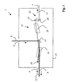
- Fig. 1 shows an inventive optical element 1.
- the optical element 1 has a first port 3, a second port 5, and a third port 7, wherein the first port 3, an illumination light beam 9 is coupled, at the second port 5 of the illumination light beam 9 is coupled out and a detection light beam 11 is coupled and to the third port 7 of the detection light beam 11 is coupled out.
- the optical element 1 includes a first acousto-optical component 13 and is designed as a replaceable module with a housing 15.
- the incident illumination light beam 9 is directed by a deflection mirror 17 onto the first acousto-optical component 13.
- the acousto-optic component 13 is configured as an AOTF, which is traversed by an acoustic wave.
- the acoustic wave is generated by one of the electrically controlled piezo sound generators.
- the frequency of the acoustic wave is selected such that only the portions of the desired wavelength of the illumination light beam 9 are directed in the direction of the second port 5.
- the remaining portions of the illumination light beam 9 which are not influenced by the acoustic excitation are directed into a beam trap 19.
- the power of the emerging from the second port 5 illumination light beam 9 can be selected, which is particularly advantageous in reflection microscopy applications.
- Crystal section and orientation of the acousto-optic component 13 are chosen so that with the same coupling direction different wavelengths are deflected in the same direction.
- the optical element 1 is the variation of the power of the illumination light beam 9, the variation of the power of at least one selectable wavelength or at least a selectable wavelength range of the illumination light beam 9 and also the complete blanking of selectable wavelengths or selectable wavelength ranges allows.
- the detection light beam 11, which is shown in dashed lines in the drawing, is incident on the acousto-optic component 13 in the opposite direction of propagation of the illumination light beam 9.
- the portions of the detection light beam 11 having the same wavelength and polarization as the illumination light beam 9 become completely or partially, depending on the amplitude of the acoustic wave directed to the deflection mirror 17 and then to the first port 3; At a reduced amplitude, the unaffected portion of the deflection mirror 17 passes.
- the optical element 1 acts like a variable neutral beam splitter whose division ratio is determined by the amplitude of the acoustic wave. If the detection light beam 11 is fluorescent light which is changed in wavelength, for example because of the Stokes or Raman shift, this is not influenced by the acoustic wave and passes the deflection mirror 17. Due to the birefringence of the acousto-optic component 13, the detection light beam 11 is split into a neat and an extraordinarily polarized beam. In addition, the neat and the extraordinarily polarized beam due to the prismatic effect of the acousto-optic device 13 are also spectrally fanned out.
- an optical compensation element 21, which consists of a further acousto-optical component 23, is provided.
- the further acousto-optic component 23 corresponds in construction to the first acousto-optical component 13. It is arranged rotated 180 degrees about the beam axis of FIG. As a result, the fanned partial beams of different polarization direction are reunited. At the same time, the spectral fanning of the first acousto-optical component 13 is reversed. At best, there remains a slight parallel offset for detection light of different wavelengths. After passing through the further acousto-optical component 23, the detection light beam 11 strikes a pair of mirrors 25 from a first mirror 27 and a second mirror 29.
- the mirror pair 25 serves to bring the detection light beam 11 onto the desired beam axis, namely the beam axis, which has the detection light beam 11 entering through the second port 5. This simplifies the interchangeability of the optical element 1 against an element with a conventional beam splitter.
- the detection light beam 11 with the first acoustooptic component 13 or also with the further acoustooptic component 23 can be spectrally selectively varied in power.
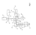
- the scanning microscope has stop elements 41, 43 which define a working position for an optical element 1 and a further optical element 47, which can optionally be introduced into this working position, and enable the positioning, without an adjustment being necessary.
- a guide member 45 which is designed as a dovetail guide is provided.
- the optical element 1 corresponds to the optical element illustrated in FIG.
- the further optical element 47 includes a dichroic beam splitter 46 for separating the illumination and detection beam path.
- the respective introduced into the working position optical element directs the influenced or uninfluenced illumination light beam 9 on a beam deflector 49 which includes a gimbal-mounted scanning mirror 51, and the illumination light beam 9 through the scanning optics 53, the tube optics 55 and the lens 57 via or through the sample 59 leads.
- the detection light beam 11 coming from the sample passes in reverse direction through the scanning optics 53, the tube optics 55 and the objective 57 and passes via the scanning mirror 51 to the optical element 1, 47, which feeds the detection light beam 11 to the detector 61, which is designed as a multiband detector ,
- the illumination pinhole usually provided in a confocal scanning microscope 63 and the detection pinhole 65 are shown schematically for the sake of completeness.
- some optical elements for guiding and shaping the light beams, as well as the drivers and supply lines for the acousto-optical components have been left out because of better clarity. These are well known to a person skilled in the art.
- Fig. 3 graphically shows the spectral characteristics of an optical element with a dichroic beam splitter (curve with reference numeral 60) compared to an optical element with an acousto-optic device (curve with reference numeral 62).
- the beam splitter is a triple dichroic optimized for the excitation wavelengths 488nm, 543nm, 633nm. For these wavelengths, a high reflectivity and correspondingly low transmission is needed. For efficient fluorescence detection, a high transmission is required in the remaining wavelength range above the excitation lines.
- the detectable fluorescence light output results from the integration of the product of beam splitter transmission and fluorescence spectrum over the wavelength range of interest.
- the transmission spectrum of an optical element with an acousto-optic component which is set to the same excitation wavelengths 488 nm, 543 nm, 633 nm is shown.
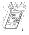
- the module shows a module 66 according to the invention with a first acousto-optical component, which is concealed in this view by its holder 67, and with a further acousto-optical component 23, which is arranged in a holder 69.
- the module has a housing 15, a first port 3, a second port 5, and a third port 7, wherein the first port 3, an illumination light beam 9 is coupled, at the second port 5 of the illumination light beam 9 is coupled out and a detection light beam 11 couples is and is coupled to the third port 7 of the detection light beam 11.
- stop surfaces 71, 73 are provided for exact positioning.
- the module can be introduced easily and without adjustment into an optical device, for example a scanning microscope or a flow cytometer, and, for example, against the optical element shown in FIG. 5 interchangeable.
- Fig. 5 shows an optical element equipped with a sliding carriage 75 in which a plurality of beam splitters 77, 79 are stored, and whose housing 15 has the same shape as that of the module shown in Fig. 4.
- the optical element can be introduced into an optical device, for example a scanning microscope or a flow cytometer, simply and without adjustment effort, and exchanged, for example, with the optical element shown in FIG. 4.
Description
Die Erfindung betrifft ein Scanmikroskop, das einen Beleuchtungs- und einen Detektionsstrahlengang festlegt, mit einem Objektiv, das sowohl im Beleuchtungs- und im Detektionsstrahlengang angeordnet ist.The invention relates to a scanning microscope, which defines an illumination and a detection beam path, with a lens which is arranged both in the illumination and in the detection beam path.
In der Scanmikroskopie wird eine Probe mit einem Lichtstrahl beleuchtet, um das von der Probe emittierte Detektionslicht, als Reflexions- oder Fluoreszenzlicht, zu beobachten. Der Fokus eines Beleuchtungslichtstrahles wird mit Hilfe einer steuerbaren Strahlablenkeinrichtung, im Allgemeinen durch Verkippen zweier Spiegel, in einer Probenebene bewegt, wobei die Ablenkachsen meist senkrecht aufeinander stehen, so dass ein Spiegel in x-, der andere in y-Richtung ablenkt. Die Verkippung der Spiegel wird beispielsweise mit Hilfe von Galvanometer-Stellelementen bewerkstelligt. Die Leistung des vom Objekt kommenden Detektionslichtes wird in Abhängigkeit von der Position des Abtaststrahles gemessen. Üblicherweise werden die Stellelemente mit Sensoren zur Ermittlung der aktuellen Spiegelstellung ausgerüstet. Das Beleuchtungslicht wird über einen Strahlteiler eingekoppelt. Das vom Objekt kommende Fluoreszenz- oder Reflexionslicht passiert den Strahlteiler und gelangt anschließend zu den Detektoren.In scanning microscopy, a sample is illuminated with a light beam to observe the detection light emitted by the sample, as reflection or fluorescent light. The focus of an illumination light beam is moved by means of a controllable beam deflection device, generally by tilting two mirrors, in a sample plane, wherein the deflection axes are usually perpendicular to one another, so that one mirror deflects in the x direction and the other in the y direction. The tilting of the mirror is accomplished, for example, with the help of galvanometer actuators. The power of the detection light coming from the object is measured as a function of the position of the scanning beam. Usually, the control elements are equipped with sensors for determining the current mirror position. The illumination light is coupled in via a beam splitter. The fluorescence or reflection light coming from the object passes through the beam splitter and then reaches the detectors.
Speziell in der konfokalen Scanmikroskopie wird ein Objekt mit dem Fokus eines Lichtstrahles in drei Dimensionen abgetastet.Especially in confocal scanning microscopy, an object with the focus of a light beam is scanned in three dimensions.
Ein konfokales Scanmikroskop umfasst im Allgemeinen eine Lichtquelle, eine Fokussieroptik, mit der das Licht der Quelle auf eine Lochblende - die sog. Anregungsblende - fokussiert wird, einen Strahlteiler, eine Strahlablenkeinrichtung zur Strahlsteuerung, eine Mikroskopoptik, eine Detektionsblende und die Detektoren zum Nachweis des Detektions- bzw. Fluoreszenzlichtes. Das Beleuchtungslicht wird über einen Strahlteiler eingekoppelt. Das vom Objekt kommende Fluoreszenz- oder Reflexionslicht gelangt über die Strahlablenkeinrichtung zurück zum Strahlteiler, passiert diesen, um anschließend auf die Detektionsblende fokussiert zu werden, hinter der sich die Detektoren befinden. Diese Detektionsanordnung wird Descan-Anordnung genannt. Detektionslicht, das nicht direkt aus der Fokusregion stammt, nimmt einen anderen Lichtweg und passiert die Detektionsblende nicht, so dass man eine Punktinformation erhält, die durch sequentielles Abtasten des Objekts mit dem Fokus des Beleuchtungslichtstrahles zu einem dreidimensionalen Bild führt. Meist wird ein dreidimensionales Bild durch schichtweise Bilddatennahme erzielt.A confocal scanning microscope generally comprises a light source, a focusing optics with which the light of the source is focused on a pinhole - the so-called excitation diaphragm, a beam splitter, a beam deflector for beam control, a microscope optics, a detection diaphragm and the detectors for detecting the detection - or fluorescent light. The illumination light is coupled in via a beam splitter. The fluorescence or reflection light coming from the object passes back to the beam splitter via the beam deflector, passes through it, and is subsequently focused onto the detection aperture behind which the detectors are located. This detection arrangement is called Descan arrangement. Detection light that does not come directly from the focus region takes a different light path and does not pass through the detection aperture, so that one obtains point information that results in a three-dimensional image by sequentially scanning the object with the focus of the illumination light beam. Usually, a three-dimensional image is achieved by layerwise image data acquisition.
Aus der Offenlegungsschrift Leica
Aus der Offenlegungsschrift
Die
Die bekannten Scanmikroskope haben gegenüber Scanmikroskopen, bei denen die Trennung von Beleuchtungs- und das Detektionslicht mit einem Strahlteiler realisiert ist, den Vorteil der spektralen Flexibilität, da das akustooptische Bauteil durch Ansteuerung mit Schallwellen unterschiedlicher Frequenz auf jede beliebige optische Wellenlänge für Beleuchtung bzw. Detektionslicht einstellbar ist. Darüber hinaus ist die spektrale Trennung bei diesen Scanmikroskopen um ein Vielfaches besser, als bei Scanmikroskopen mit Strahlteilern. Bei reflektierenden Proben ist auf Grund erhöhter Lichtleistungsverluste in den akustooptischen Bauteilen die Verwendung von Scanmikroskopen mit einem Strahlteiler, der beispielsweise als Neutralteiler ausgeführt sein kann, zu bevorzugen. Scanmikroskope mit Strahlteilern sind außerdem erheblich kostengünstiger.The known scanning microscopes have compared to scanning microscopes, in which the separation of illumination and the detection light is realized with a beam splitter, the advantage of spectral flexibility, since the acousto-optic component adjustable by control with sound waves of different frequencies to any optical wavelength for illumination or detection light is. In addition, the spectral separation of these scanning microscopes is many times better than with scanning microscopes with beam splitters. In the case of reflective specimens, the use of scanning microscopes with a beam splitter, which can be embodied, for example, as a neutral divider, is to be preferred due to increased light power losses in the acousto-optical components. Scanning microscopes with beam splitters are also significantly cheaper.
Kommerzielle Scanmikroskope beinhalten meistens ein Mikroskopstativ, wie es auch in der konventionellen Lichtmikroskopie verwendet wird. In der Regel sind insbesondere konfokale Scanmikroskope auch als konventionelle Lichtmikroskope verwendbar. In der konventionellen Fluoreszenzauflichtmikroskopie wird aus dem Licht einer Lichtquelle, beispielsweise einer Bogenlampe, mit Hilfe eines Farbfilters, dem sog. Anregungsfilter, der Anteil in den mikroskopischen Strahlengang eingekoppelt, der den gewünschten Wellenlängenbereich zur Fluoreszenzanregung aufweist. Die Einkopplung in den Strahlengang des Mikroskops erfolgt mit Hilfe eines dichroitischen Strahlteilers, der das Anregungslicht zur Probe reflektiert, während er das von der Probe ausgehende Fluoreszenzlicht weitgehend ungehindert passieren lässt. Das von der Probe rückgestreute Anregungslicht wird mit einem Sperrfilter zurückgehalten, der für die Fluoreszenzstrahlung jedoch durchlässig ist. Die optimale Kombination aufeinander abgestimmter Filter und Strahlteiler zu einem leicht austauschbaren modularen Filterblock ist seit langem üblich. Meist sind die Filterblöcke in einem Revolver innerhalb des Mikroskops, als Teil sog. Fluoreszenz-Auftichtilluminatoren, angeordnet, so dass ein schneller und einfacher Austausch ermöglicht ist. Eine Fluoreszenzeinrichtung für Invers-Mikroskope, die eine Revolverhalterung für die Aufnahme von mehreren Fluoreszenzwürfeln enthält, welche auf einer Schublade drehbar gehaltert ist, ist beispielsweise in der
Der Erfindung liegt daher die Aufgabe zugrunde, ein Scanmikroskop vorzuschlagen, das universell einsetzbar ist und die Vorteile der unterschiedlichen bekannten Scanmikroskope bietet. Weiterhin soll das Scanmikroskop ohne oder allenfalls mit geringem Justieraufwand nachrüstbar sein.The invention is therefore based on the object to propose a scanning microscope, which is universally applicable and offers the advantages of different known scanning microscopes. Furthermore, the scanning microscope without or at best be retrofitted with little adjustment effort.
Obige Aufgabe wird durch ein Scanmikroskop gelöst, das die Merkmale des Anspruchs 1 umfasst.The above object is achieved by a scanning microscope comprising the features of
Die Erfindung hat neben dem Vorteil der Nachrüstbarkeit den weitem Vorteil der universellen Variierbarkeit der Leistung des Beleuchtungslichts mindestens einer beliebig auswählbaren Wellenlänge oder mindestens eines beliebig auswählbaren Wellenlängenbereichs, wobei auch eine verlustarme Reflexionsmikroskopie ermöglicht ist.The invention has the advantage of retrofitting the far-reaching advantage of universal variability of the power of the illumination light at least one arbitrarily selectable wavelength or at least one arbitrarily selectable wavelength range, wherein a low-loss reflection microscopy is possible.
In einer bevorzugen Ausgestaltung des Scanmikroskops ist das akustooptische Bauteil als AOTF (acusto optical tunable filter) ausgestaltet. Eine Ausgestaltungsform mit einem AOD (akustooptischer Deflektor) ist realisierbar.In a preferred embodiment of the scanning microscope, the acousto-optical component is configured as AOTF (acusto optical tunable filter). An embodiment with an AOD (acousto-optical deflector) is feasible.
In der erfindungsgemäßen Ausgestaltung ist ein optisches Kompensationselement vorgesehen, das eine Doppelbrechung, die zu einer polarisationsabhängigen räumlichen Aufspaltung des Detektionslichtstrahles führt, des akustooptischen Bauteils kompensiert. Die Doppelbrechungseigenschaften sind auf die Kristallstruktur des akustooptischen Bauteils zurückzuführen. Durch die Anordnung der Grenzflächen weisen manche akustooptischen Bauteile eine ungewollte Prismenwirkung auf den Detektionslichtstrahl auf, die in der erfindungsgemäßen Ausgestaltung durch ein optisches Kompensationselement kompensiert ist. Die Prismenwirkung verursacht eine räumlich spektrale Aufspaltung des Detektionslichtstrahles. In der erfindungsgemäßen Ausführungsform Kompensiert das optische Kompensationselement sowohl eine ungewollte Prismenwirkung, als auch eine Doppelbrechung, da das optische Kompensationselement ein weiteres akustooptisches Bauteil ist. Das weitere akustooptische Bauteil und das erste akustooptische Bauteil weisen dabei die gleiche äußere Form und die gleiche Kristallstruktur auf. Das weitere akustooptische Bauteil und das erste akustooptische Bauteil sind bezüglich der Ausbreitungsrichtung des auf das erste akustooptische Bauteil treffenden Detektionslichtstrahls gegeneinander um 180 Grad verdreht orientiert. In der Regel ist das so orientierte weitere akustooptische Bauteil seitlich zu der durch die Ausbreitungsrichtung des auf das erste akustooptische Bauteil treffenden Detektionslichtstrahls definierten Achse versetzt, damit der Detektionslichtstrahl auf das weitere akustooptische Bauteil trifft. Der Abstand von ersten akustooptischem Bauteil zum weiteren akustooptische Bauteil ist in dieser Ausführung möglichst klein gewählt, um eine zu große räumliche Aufspaltung des Detektionslichtstrahls zwischen akustooptischem Bauteil und dem weiteren akustooptischen Bauteil zu vermeiden. Räumliche Aufspaltungen in der Größenordnung von einem halben Strahldurchmesser sind akzeptabel.In the embodiment according to the invention, an optical compensation element is provided which compensates for a birefringence which leads to a polarization-dependent spatial splitting of the detection light beam of the acousto-optical component. The birefringence properties are due to the crystal structure of the acousto-optic device. As a result of the arrangement of the interfaces, some acousto-optical components have an undesired prismatic effect on the detection light beam, which in the embodiment according to the invention is compensated by an optical compensation element. The prism effect causes a spatial spectral splitting of the detection light beam. In the embodiment according to the invention, the optical compensation element compensates for both an unwanted prism effect and a birefringence, since the optical compensation element is a further acousto-optic component. The further acousto-optic component and the first acousto-optic component have the same external shape and the same crystal structure. The further acousto-optic component and the first acousto-optic component are oriented rotated relative to each other by 180 degrees relative to the propagation direction of the detection light beam impinging on the first acousto-optic component. As a rule, the further acousto-optic component oriented in this way is offset laterally relative to the axis defined by the propagation direction of the detection light beam impinging on the first acoustooptic component, so that the detection light beam strikes the further acousto-optic component. The distance from the first acousto-optic component to the other In this embodiment, the acousto-optic component is chosen to be as small as possible in order to avoid excessive spatial splitting of the detection light beam between the acousto-optic component and the further acousto-optic component. Spatial splits on the order of half the beam diameter are acceptable.
In einer anderen Ausgestaltung ist das weitere akustooptische Bauteil mit dem ersten akustooptischen Bauteil direkt oder über ein Zwischenbauteil verkittet.In another embodiment, the further acousto-optic component is cemented to the first acousto-optic component directly or via an intermediate component.
Vorzugsweise beinhaltet das optische Modul Elemente zur Strahlführung und Elemente zur Strahlformung. Hierbei handelt es sich beispielsweise um Linsen, Spiegel, Gitter, Hohlspiegel und Glasblöcke. Insbesondere ist ein Ausgleich eines beim Durchlaufen des akustooptischen Bauteils entstehenden Strahlversatzes bzw. einer Strahlablage vorgesehen.The optical module preferably contains elements for beam guidance and elements for beam shaping. These are, for example, lenses, mirrors, gratings, concave mirrors and glass blocks. In particular, a compensation of a beam offset or a beam deposit resulting from passing through the acousto-optical component is provided.
In einer anderen Ausführungsform ist eine Temperaturstabilisierung des ersten akustooptischen Bauteils bzw. des zweiten akustooptischen Bauteils vorgesehen. In einer weiteren Ausführungsvariante ist zur Vermeidung von Nachteilen durch Temperaturschwankungen oder von Schwankungen der Wellenlänge des Beleuchtungslichtstrahls vorgesehen, die Hochfrequenz in Abhängigkeit von der Temperatur zu steuern oder zu regeln. Eine andere Variante sieht in Verwirklichung dieses Ziels vor, die Wellenlänge des Beleuchtungslichtstrahles in Abhängigkeit von der Temperatur zu steuern oder zu regeln.In another embodiment, a temperature stabilization of the first acousto-optic component or the second acousto-optic component is provided. In a further embodiment variant, in order to avoid disadvantages due to temperature fluctuations or fluctuations in the wavelength of the illumination light beam, it is provided to control or regulate the high frequency as a function of the temperature. Another variant provides in realization of this goal to control the wavelength of the illumination light beam as a function of the temperature or to regulate.
In einer bevorzugen Ausgestaltung ist ein Linemultiplexen vorgesehen, wobei eine Probenzeile mehrmals gescannt wird, jedoch immer mit Beleuchtungslicht einer anderen Wellenlänge beaufschlagt wird. Auch ein (automatisches) Umschalten der Wellenlänge des Beleuchtungslichtes für aufeinander folgende Probenzeilen ist möglich.In a preferred embodiment, a linear multiplexing is provided, wherein a sample line is scanned several times, but is always acted upon by illumination light of a different wavelength. It is also possible to (automatically) switch the wavelength of the illumination light for successive sample lines.
In einer ganz besonders bevorzugten Ausführungsform sind Führungs- und Anschlagelemente zur Positionierung des Moduls vorgesehen. Diese beinhalten beispielsweise Gleitschienen, Schwalbenschwanzführungen oder eine Bajonettfassung, die ein einfaches und zuverlässiges Einbringen und Positionieren ermöglichen. Weiterhin sind Anschlagelemente vorgesehen, die eine Arbeitsposition des Moduls im Beleuchtungs- und Detektionsstrahlengang definieren und die derart ausgestaltet sind, dass das positionierte Auskoppelelement automatisch in Bezug auf den Detektionsstrahlengang justiert ist und nach der Positionierung keine weitere Justierung des Auskoppelelements erforderlich ist.In a very particularly preferred embodiment, guiding and stop elements are provided for positioning the module. These include, for example, slide rails, dovetail guides or a bayonet mount, which provides a simple and reliable insertion and Enable positioning. Furthermore, stop elements are provided which define a working position of the module in the illumination and detection beam path and which are configured such that the positioned decoupling element is automatically adjusted with respect to the detection beam path and after positioning no further adjustment of the decoupling element is required.
In einer anderen Ausführungsform ist ein Revolver oder ein Schiebeschlitten, der mindestens eine Elementaufnahme aufweist, zur Positionierung des Moduls vorgesehen, wobei an oder in der Elementaufnahme das Modul derart angebracht ist, dass das Modul durch einfaches Drehen des Revolvers oder durch Schieben des Schiebeschlittens in dem Beleuchtungs- und Detektionsstrahlengang positionierbar ist. Eine Justierung des Moduls erfolgt nur einmalig beim Anbringen des Moduls in dem oder an dem Revolver oder Schiebeschlitten. Der weist vorzugsweise eine Einrastvorrichtung auf, die den Revolver oder den Schiebeschlitten lösbar fixiert, wenn das Modul in dem Beleuchtungs- und Detektionsstrahlengang positioniert ist. In einer weiteren Ausführungsvariante weist der Revolver oder der Schiebeschlitten mehrere Elementaufnahmen auf, in den Strahlteiler, die als dichroitische Strahlteiler, als Neutralteiler oder als Farbstrahlteiler ausgeführt sind, angebracht sind. Diese erfindungsgemäße Lösung ist hochflexibel, da das Modul und mehrere unterschiedliche Strahlteiler unterschiedlicher spektraler Eigenschaften bereit gehalten werden und einfach ausgetauscht werden können.In another embodiment, a revolver or a sliding carriage, which has at least one element receptacle, provided for positioning the module, wherein on or in the element receptacle, the module is mounted such that the module by simply rotating the turret or by sliding the sliding carriage in the Illumination and detection beam path can be positioned. An adjustment of the module is only once when attaching the module in or on the revolver or sliding carriage. It preferably has a latching device which releasably fixes the revolver or the sliding carriage when the module is positioned in the illumination and detection beam path. In a further embodiment variant, the revolver or sliding carriage has a plurality of element receptacles, in which the beam splitters, which are designed as dichroic beam splitters, as neutral dividers or as color beam splitters, are mounted. This solution according to the invention is highly flexible, since the module and several different beam splitters of different spectral properties are kept ready and can be easily exchanged.
In einer besonders vorteilhaften Ausgestaltung weisen der aus dem Modul ausgekoppelte Beleuchtungslichtstrahl und der aus dem Modul ausgekoppelte Detektionslichtstrahl parallele optische Achsen auf. Diese Ausgestaltung vereinfacht die Auswechselbarkeit mit auf planparallelen Substraten basierenden Strahlteilern.In a particularly advantageous embodiment, the illumination light beam coupled out of the module and the detection light beam coupled out of the module have parallel optical axes. This embodiment simplifies the interchangeability with beam splitters based on plane-parallel substrates.
In der Zeichnung ist der Erfindungsgegenstand schematisch dargestellt und wird anhand der Figuren nachfolgend beschrieben, wobei gleich wirkende Elemente mit denselben Bezugszeichen versehen sind. Dabei zeigen:
- Fig. 1
- Ein erfindungsgemäßes optisches Element,
- Fig.2
- ein erfindungsgemäßes Scanmikroskop,
- Fig. 3
- grafisch die spektralen Eigenschaften zweier optischer Elemente
- Fig. 4
- ein erfindungsgemäßes optisches Element und
- Fig. 5
- ein weiteres optisches Element.
- Fig. 1
- An optical element according to the invention,
- Fig.2
- a scanning microscope according to the invention,
- Fig. 3
- graphically the spectral properties of two optical elements
- Fig. 4
- an inventive optical element and
- Fig. 5
- another optical element.
Fig. 1 zeigt ein erfindungsgemäßes optisches Element 1. Das optische Element 1 weist einen ersten Port 3, einen zweiten Port 5, und einen dritten Port 7 auf, wobei dem ersten Port 3 ein Beleuchtungslichtstrahl 9 einkoppelt ist, an dem zweiten Port 5 der Beleuchtungslichtstrahl 9 auskoppelt ist und ein Detektionslichtstrahl 11 einkoppelt ist und an den dritten Port 7 der Detektionslichtstrahl 11 auskoppelt ist. Das optische Element 1 beinhaltet ein erstes akustooptisches Bauteil 13 und ist als austauschbares Modul mit einem Gehäuse 15 ausgestaltet. Der einfallende Beleuchtungslichtstrahl 9 wird von einem Umlenkspiegel 17 auf das erste akustooptische Bauteil 13 gelenkt. Das akustooptische Bauteil 13 ist als AOTF ausgestaltet, der von einer akustischen Welle durchlaufen ist. Die akustische Welle wird von einem der elektrisch angesteuerten Piezo-Schallerzeuger generiert. Die Frequenz der akustische Welle wird so gewählt, dass nur die Anteile der gewünschten Wellenlänge des Beleuchtungslichtstrahls 9 in Richtung des zweiten Ports 5 gelenkt werden. Die übrigen, von der akustischen Anregung nicht beeinflussten Anteile des Beleuchtungslichtstrahls 9 werden in eine Strahlfalle 19 gelenkt. Durch Variation der Amplitude der akustischen Welle ist die Leistung des aus dem zweiten Port 5 austretenden Beleuchtungslichtstrahls 9 auswählbar, was insbesondere bei reflexionsmikroskopischen Anwendungen von besonderem Vorteil ist. Kristallschnitt und Orientierung des akustooptischen Bauteils 13 sind dabei so gewählt, dass bei gleicher Einkoppelrichtung verschiedene Wellenlängen in die gleiche Richtung abgelenkt werden.Fig. 1 shows an inventive
Mit dem optischen Element 1 ist die Variierung der Leistung des Beleuchtungslichtstrahls 9, die Variierung der Leistung mindestens einer auswählbaren Wellenlänge oder mindestens eines auswählbaren Wellenlängenbereichs des Beleuchtungslichtstrahls 9 und auch die vollständige Ausblendung auswählbarer Wellenlängen oder auswählbarer Wellenlängenbereiche ermöglicht. Der Detektionslichtstrahl 11, der in der Zeichnung gestrichelt dargestellt ist, trifft mit entgegengesetzter Ausbreitungsrichtung zum Beleuchtungslichtstrahls 9 auf das akustooptische Bauteil 13. Die Anteile des Detektionslichtstrahl 11 mit gleicher Wellenlänge und Polarisation wie die des Beleuchtungslichtstrahls 9 werden je nach Amplitude der akustischen Welle vollständig oder teilweise auf den Umlenkspiegel 17 und anschließend zum ersten Port 3 gelenkt; bei verminderter Amplitude gelangt der unbeeinflusste Anteil an dem Umlenkspiegel 17 vorbei. Handelt es sich bei dem Detektionslichtstrahl 11 beispielsweise um Reflexionslicht, so wirkt das optische Element 1 wie ein variabler Neutralstrahlteiler, dessen Teilungsverhältnis durch die Amplitude der akustischen Welle bestimmt ist. Handelt es sich bei dem Detektionslichtstrahl 11 um Fluoreszenzlicht, das z.B. aufgrund der Stokes-oder Ramanverschiebung in der Wellenlänge verändert ist, wird dieses von der akustischen Welle nicht beeinflusst und gelangt am Umlenkspiegel 17 vorbei. Aufgrund der Doppelbrechung des akustooptischen Bauteils 13 ist der Detektionslichtstrahl 11 in einen ordentlich und einen außerordentlich polarisierten Strahl aufgespalten. Außerdem sind jeweils der ordentlich und der außerordentlich polarisierte Strahl aufgrund der Prismenwirkung des akustooptischen Bauteils 13 auch spektral aufgefächert. Zur Kompensation ist ein optisches Kompensationselement 21, das aus einem weiteren akustooptischen Bauteil 23 besteht, vorgesehen. Das weitere akustooptische Bauteil 23 entspricht im Aufbau dem ersten akustooptischen Bauteil 13. Es ist um 180 Grad um die Strahlachse von 13 gedreht angeordnet. Dadurch werden die aufgefächerten Teilstrahlen unterschiedlicher Polarisationsrichtung wieder vereinigt. Gleichzeitig wird die spektrale Auffächerung des ersten akustooptischen Bauteils 13 rückgängig gemacht. Es verbleibt allenfalls ein geringer Parallelversatz für Detektionslicht unterschiedlicher Wellenlängen. Nach Durchlaufen des weiteren akustooptischen Bauteils 23 trifft der Detektionslichtstrahl 11 auf ein Spiegelpaar 25 aus einem ersten Spiegel 27 und einem zweiten Spiegel 29. Das Spiegelpaar 25 dient dazu, den Detektionslichtstrahl 11 auf die gewünschte Strahlachse, nämlich die Strahlachse, die der durch den zweiten Port 5 eintretende Detektionslichtstrahles 11 aufweist, zu bringen. Dies vereinfacht die Austauschbarkeit des optischen Elements 1 gegen ein Element mit einem konventionellen Strahlteiler. Ebenso, wie der Beleuchtungslichtstrahl 9 kann der Detektionslichtstrahl 11 mit dem ersten akustooptischen Bauteil 13 oder auch mit dem weiteren akustooptischen Bauteil 23 spektral selektiv in der Leistung variiert werden.With the
Fig. 2 zeigt ein erfindungsgemäßes Scanmikroskop, das als konfokales Scanmikroskop ausgeführt ist, mit zwei Lasern 31, 33, deren Emissionslichtstrahlen 35, 37, die unterschiedliche Wellenlängen aufweisen, mit dem dichroitischen Strahlvereiniger 39 zu einem Beleuchtungslichtstrahl 9 vereinigt werden. Das Scanmikroskop weist Anschlagelemente 41, 43 auf, die eine Arbeitsposition für ein optisches Element 1 und ein weiteres optisches Element 47, die wahlweise in diese Arbeitsposition einbringbar sind, definieren und die Positionierung ermöglichen, ohne dass eine Justierung erforderlich ist. Außerdem ist ein Führungselement 45, das als Schwalbenschanzführung ausgebildet ist, vorgesehen. Das optische Element 1 entspricht dem in Fig. 1 illustrierten optischen Element. Das weitere optische Element 47 beinhaltet einen dichroitischen Strahlteiler 46 zur Separierung von Beleuchtungs- und Detektionsstrahlengang. Das jeweils in die Arbeitsposition eingebrachte optische Element lenkt den beeinflussten oder unbeeinflussten Beleuchtungslichtstrahl 9 auf eine Strahlablenkeinrichtung 49, die einen kardanisch aufgehängten Scanspiegel 51 beinhaltet, und den Beleuchtungslichtstrahl 9 durch die Scanoptik 53, die Tubusoptik 55 und das Objektiv 57 über bzw. durch die Probe 59 führt. Der von der Probe kommende Detektionslichtstrahl 11 durchläuft in umgekehrter Richtung die Scanoptik 53, die Tubusoptik 55 und das Objektiv 57 und gelangt über den Scanspiegel 51 zum optischen Element 1, 47, das den Detektionslichtstrahl 11 dem Detektor 61, der als Multibanddetektor ausgeführt ist, zuleitet. Das bei einem konfokalen Scanmikroskop üblicherweise vorgesehene Beleuchtungspinhole 63 und das Detektionspinhole 65 sind der Vollständigkeit halber schematisch eingezeichnet. Weggelassen sind wegen der besseren Anschaulichkeit hingegen einige optische Elemente zur Führung und Formung der Lichtstrahlen, sowie die Treiber und Zuleitungen für die akustooptischen Bauteile. Diese sind einem auf diesem Gebiet tätigen Fachmann hinlänglich bekannt.2 shows a scanning microscope according to the invention, which is designed as a confocal scanning microscope, with two
Fig. 3 zeigt grafisch die spektralen Eigenschaften eines optischen Elements mit einem dichroitischen Strahlteiler (Kurve mit Bezugszeichen 60) im Vergleich zu einem optischen Element mit einem akustooptischen Bauteil (Kurve mit Bezugszeichen 62). Beim Strahlteiler handelt es sich um einen dreifach Dichroiten, der für die Anregungswellenlängen 488nm, 543nm, 633nm optimiert wurde. Für diese Wellenlängen wird eine hohe Reflektivität und entsprechend geringe Transmission benötigt. Für eine effiziente Fluoreszenzdetektion wird im restlichen Wellenlängenbereich oberhalb der Anregungslinien eine hohe Transmission gefordert. Die detektierbare Fluoreszenz-Lichtleistung ergibt sich aus der Integration des Produkts von Strahlteiler-Transmission und Fluoreszenzspektrum über den interessierenden Wellenlängenbereich. Das Transmissionsspektrum eines optischen Element mit einem akustooptischen Bauteil, welcher auf die gleichen Anregungswellenlängen 488nm, 543nm, 633nm eingestellt ist, ist dargestellt.Fig. 3 graphically shows the spectral characteristics of an optical element with a dichroic beam splitter (curve with reference numeral 60) compared to an optical element with an acousto-optic device (curve with reference numeral 62). The beam splitter is a triple dichroic optimized for the excitation wavelengths 488nm, 543nm, 633nm. For these wavelengths, a high reflectivity and correspondingly low transmission is needed. For efficient fluorescence detection, a high transmission is required in the remaining wavelength range above the excitation lines. The detectable fluorescence light output results from the integration of the product of beam splitter transmission and fluorescence spectrum over the wavelength range of interest. The transmission spectrum of an optical element with an acousto-optic component which is set to the same excitation wavelengths 488 nm, 543 nm, 633 nm is shown.
Fig. 4 zeigt ein erfindungsgemäßes Modul 66 mit einem ersten akustooptischen Bauteil, das in dieser Ansicht von seiner Halterung 67 verdeckt ist, und mit einem weiteren akustooptischen Bauteil 23, das in einer Halterung 69 angeordnet ist. Das Modul weist ein Gehäuse 15, einen ersten Port 3, einen zweiten Port 5, und einen dritten Port 7 auf, wobei dem ersten Port 3 ein Beleuchtungslichtstrahl 9 einkoppelt ist, an dem zweiten Port 5 der Beleuchtungslichtstrahl 9 auskoppelt ist und ein Detektionslichtstrahl 11 einkoppelt ist und an den dritten Port 7 der Detektionslichtstrahl 11 auskoppelt ist. Weiterhin sind Anschlagflächen 71, 73 zur exakten Positionierung vorgesehen. Das Modul ist einfach und ohne Justieraufwand in ein optisches Gerät, beispielsweise ein Scanmikroskop oder ein Durchflusszytometer einbringbar und beispielsweise gegen das in Fig. 5 gezeigte optische Element austauschbar.4 shows a
Fig. 5 zeigt ein optisches Element, das mit einem Schiebeschlitten 75, in dem mehrere Strahlteiler 77, 79 bevorratet sind, ausgerüstet ist und dessen Gehäuse 15 dieselbe Form aufweist, wie die des in Fig. 4 gezeigten Moduls. Das optische Element ist einfach und ohne Justieraufwand in ein optisches Gerät, beispielsweise ein Scanmikroskop oder ein Flußzytometer einbringbar und beispielsweise gegen das in Fig. 4 gezeigte optische Element austauschbar.Fig. 5 shows an optical element equipped with a sliding carriage 75 in which a plurality of
Die Erfindung wurde in Bezug auf eine besondere Ausführungsform beschrieben. Es ist jedoch selbstverständlich, dass Änderungen und Abwandlungen durchgeführt werden können, ohne dabei den Schutzbereich der nachstehenden Ansprüche zu verlassen.The invention has been described with reference to a particular embodiment. However, it is to be understood that changes and modifications may be made without departing from the scope of the following claims.
- 11
- optisches Elementoptical element
- 33
- erster Portfirst port
- 55
- zweiter Portsecond port
- 77
- dritter Portthird port
- 99
- BeleuchtungslichtstrahlIlluminating light beam
- 1111
- DetektionslichtstrahlDetection light beam
- 1313
- erstes akustooptisches Bauteilfirst acousto-optic component
- 1515
- Gehäusecasing
- 1717
- Umlenkspiegeldeflecting
- 2121
- optisches Kompensationselementoptical compensation element
- 2323
- weiteres akustooptisches Bauteilanother acousto-optic component
- 2525
- Spiegelpaarmirror pair
- 2727
- erster Spiegelfirst mirror
- 2929
- zweiter Spiegelsecond mirror
- 3131
- Laserlaser
- 3333
- Laserlaser
- 3535
- EmissionslichtstrahlEmission light beam
- 3737
- EmissionslichtstrahlEmission light beam
- 3939
- dichroitischer Strahlvereinigerdichroic beam combiner
- 4141
- Anschlagelementstop element
- 4343
- Anschlagelementstop element
- 4545
- Führungselementguide element
- 4646
- Strahlteilerbeamsplitter
- 4747
- weiteres optisches Elementanother optical element
- 4949
- StrahlablenkeinrichtungBeam deflector
- 5151
- Scanspiegelscanning mirror
- 5353
- Scanoptikscan optics
- 5555
- Tubusoptiktube optical system
- 5757
- Objektivlens
- 5959
- Probesample
- 6161
- Detektordetector
- 6363
- BeleuchtungspinholeIllumination pinhole
- 6565
- DetektionspinholeDetection pinhole
- 6767
- Halterungbracket
- 6969
- Halterungbracket
- 7171
- Anschlagflächestop surface
- 7373
- Anschlagflächestop surface
- 7575
- Schiebeschlittensliding table
Claims (5)
- Scanning microscope that defines an illumination beam path and a detection beam path, comprising an objective (57), which is arranged in both the illumination beam path and the detection beam path, a first acousto-optical component (31), which separates the illumination beam path and the detection beam path at a fixed angular relationship to one another, being provided in the illumination beam path and the detection beam path (9, 11), and a further acousto-optical component, which compensates for a double refraction and prismatic effect of the acousto-optical component (13), being arranged as compensation element (21) in the detection beam path, characterized in that at least one first acousto-optical component (13) and the compensation element (21) are arranged in a module (66), which has a housing (15), that the first acousto-optical component (13) and the further acousto-optical component (21) are of the same construction, and that the further acousto-optical component (21) is rotated by 180° in its arrangement relative to the first acousto-optical component (13).
- Scanning microscope according to Claim 1, characterised in that the distance of the further acousto-optical component (21) from the first acousto-optical component (13) is so small that a spectral splitting, caused by the first acousto-optical component (13), of a detection light bundle extending along the detection beam path is smaller at the further acousto-optical component (21) than half the diameter of the unsplitted detection light bundle.
- Scanning microscope according to Claim 1, characterised in that the scanning microscope is provided with guide elements (46) and stop elements (41, 43), and that the housing (15) of the module (66) has stop faces for precise positioning of the module (66) in the scanning microscope.
- Scanning microscope according to Claim 1, characterised in that the housing has at least three ports (3, 5, 7), such that the illuminating light beam (9) can be coupled in at a first port (3), the illuminating light beam (9) can be coupled out and a detection light beam (11) can be coupled in at a second port (5), and the detection light beam (11) can be coupled out at a third port (7).
- Scanning microscope according to Claim 4, characterised in that the illuminating light beam (9) coupled out and the detection light beam (11) coupled out have parallel optical axes.
Applications Claiming Priority (2)
| Application Number | Priority Date | Filing Date | Title |
|---|---|---|---|
| DE10137154 | 2001-07-30 | ||
| DE10137154A DE10137154A1 (en) | 2001-07-30 | 2001-07-30 | Scanning microscope and optical element |
Publications (3)
| Publication Number | Publication Date |
|---|---|
| EP1281997A2 EP1281997A2 (en) | 2003-02-05 |
| EP1281997A3 EP1281997A3 (en) | 2004-02-04 |
| EP1281997B1 true EP1281997B1 (en) | 2007-09-12 |
Family
ID=7693635
Family Applications (1)
| Application Number | Title | Priority Date | Filing Date |
|---|---|---|---|
| EP02102013A Expired - Lifetime EP1281997B1 (en) | 2001-07-30 | 2002-07-09 | Scanning microscope |
Country Status (4)
| Country | Link |
|---|---|
| US (2) | US6850358B2 (en) |
| EP (1) | EP1281997B1 (en) |
| JP (1) | JP2003066340A (en) |
| DE (2) | DE10137154A1 (en) |
Cited By (1)
| Publication number | Priority date | Publication date | Assignee | Title |
|---|---|---|---|---|
| WO2022033663A1 (en) | 2020-08-11 | 2022-02-17 | Leica Microsystems Cms Gmbh | Beam splitting device |
Families Citing this family (12)
| Publication number | Priority date | Publication date | Assignee | Title |
|---|---|---|---|---|
| DE102004030208B3 (en) * | 2004-06-22 | 2005-12-15 | Leica Microsystems Heidelberg Gmbh | Reflected-light microscope, has acousto-optical component in illumination beam path and observation beam path coupled to splitter-combiner |
| DE102004034981A1 (en) * | 2004-07-16 | 2006-02-02 | Carl Zeiss Jena Gmbh | Scanning microscope with point-shaped light source distribution and use |
| DE102007024075B4 (en) | 2007-05-22 | 2022-06-09 | Leica Microsystems Cms Gmbh | Tunable acousto-optic filter element, adjustable light source, microscope and acousto-optic beam splitter |
| DE102007053199A1 (en) * | 2007-11-06 | 2009-05-14 | Leica Microsystems Cms Gmbh | Device and method for controlling an acousto-optic component |
| US9229294B2 (en) | 2010-05-06 | 2016-01-05 | Leica Microsystems Cms Gmbh | Apparatus and method for operating an acousto-optical component |
| WO2012049831A1 (en) | 2010-10-14 | 2012-04-19 | 株式会社ニコン | Structured illumination device, structured illumination microscope device, and surface shape measurement device |
| US10048480B2 (en) * | 2011-01-07 | 2018-08-14 | Zeta Instruments, Inc. | 3D microscope including insertable components to provide multiple imaging and measurement capabilities |
| DE102011013614A1 (en) * | 2011-03-08 | 2012-09-13 | Carl Zeiss Microimaging Gmbh | Laser scanning microscope and method of its operation |
| DE102012001854A1 (en) * | 2012-02-01 | 2013-08-01 | Leica Microsystems (Schweiz) Ag | Special lighting Operations stereomicroscope |
| US9239443B2 (en) * | 2012-06-05 | 2016-01-19 | Sutter Instrument Company | Linear optical filter system and method |
| JP6768289B2 (en) * | 2015-12-01 | 2020-10-14 | キヤノン株式会社 | Scanning electron microscope |
| EP3252512A1 (en) * | 2016-06-03 | 2017-12-06 | Leica Instruments (Singapore) Pte. Ltd. | Interchangeable optical module and microscopic apparatus |
Family Cites Families (11)
| Publication number | Priority date | Publication date | Assignee | Title |
|---|---|---|---|---|
| US3632187A (en) * | 1969-11-05 | 1972-01-04 | Ibm | Light deflector and scanner |
| DE8308331U1 (en) * | 1983-03-21 | 1983-06-09 | Ernst Leitz Wetzlar Gmbh, 6330 Wetzlar | CONDENSER HOUSING FOR MICROSCOPES |
| DE4404186C2 (en) | 1993-05-04 | 1998-12-10 | Ruhrtal Gmbh | High voltage switching device |
| JP2871547B2 (en) * | 1995-09-08 | 1999-03-17 | 日本電気株式会社 | Optical spectrum analyzer apparatus and optical amplifier control method |
| US5984861A (en) * | 1997-09-29 | 1999-11-16 | Boston Scientific Corporation | Endofluorescence imaging module for an endoscope |
| DE19906757B4 (en) * | 1998-02-19 | 2004-07-15 | Leica Microsystems Heidelberg Gmbh | microscope |
| EP1055144B1 (en) * | 1998-02-19 | 2015-01-14 | Leica Microsystems CMS GmbH | Optical arrangement with a spectrally selective element |
| DE19861383B4 (en) * | 1998-06-18 | 2008-03-27 | Carl Zeiss Jena Gmbh | Laser scanning microscope |
| DE19859314A1 (en) * | 1998-12-22 | 2000-06-29 | Zeiss Carl Jena Gmbh | Light diffraction device for separating excitation and emission light in confocal microscope e.g. laser scanning microscope, uses at least one diffraction element for diffraction of selected wavelength of excitation light |
| DE19944355B4 (en) * | 1999-09-16 | 2004-11-18 | Leica Microsystems Heidelberg Gmbh | Optical arrangement |
| DE10033549A1 (en) * | 2000-07-11 | 2002-01-24 | Leica Microsystems | Optical structure for deflecting a beam of light in two directions lying perpendicular to each other has two mirrors each rotated by a rotating drive around x/y axes perpendicular to each other. |
-
2001
- 2001-07-30 DE DE10137154A patent/DE10137154A1/en not_active Ceased
-
2002
- 2002-07-09 EP EP02102013A patent/EP1281997B1/en not_active Expired - Lifetime
- 2002-07-09 DE DE50210876T patent/DE50210876D1/en not_active Expired - Lifetime
- 2002-07-29 JP JP2002219650A patent/JP2003066340A/en active Pending
- 2002-07-29 US US10/207,428 patent/US6850358B2/en not_active Expired - Lifetime
-
2004
- 2004-12-15 US US11/012,523 patent/US7016101B2/en not_active Expired - Lifetime
Non-Patent Citations (1)
| Title |
|---|
| None * |
Cited By (1)
| Publication number | Priority date | Publication date | Assignee | Title |
|---|---|---|---|---|
| WO2022033663A1 (en) | 2020-08-11 | 2022-02-17 | Leica Microsystems Cms Gmbh | Beam splitting device |
Also Published As
| Publication number | Publication date |
|---|---|
| US7016101B2 (en) | 2006-03-21 |
| DE50210876D1 (en) | 2007-10-25 |
| JP2003066340A (en) | 2003-03-05 |
| EP1281997A3 (en) | 2004-02-04 |
| US20050099673A1 (en) | 2005-05-12 |
| US20030021018A1 (en) | 2003-01-30 |
| US6850358B2 (en) | 2005-02-01 |
| EP1281997A2 (en) | 2003-02-05 |
| DE10137154A1 (en) | 2003-02-20 |
Similar Documents
| Publication | Publication Date | Title |
|---|---|---|
| EP1421427B1 (en) | Optical arrangement and scan microscope | |
| DE19835072A1 (en) | Arrangement for illumination and/or detection in laser scanning microscope has selectively switchable micro-mirror arrangement in illumination and/or detection beam paths for wavelength selection | |
| EP1664888B1 (en) | Scanning microscope with evanescent wave illumination | |
| DE102012017920B4 (en) | Optical arrangement and light microscope | |
| DE102012017917B4 (en) | Microscope module and light microscope as well as methods and data storage media | |
| DE102012203736A1 (en) | Scanning microscope with spectral detection | |
| EP1164406A2 (en) | Method and device for illuminating an object | |
| DE102004034962A1 (en) | Microscope with increased resolution | |
| EP1617268A2 (en) | Laser scanning microscope with an illumination unit | |
| EP1281997B1 (en) | Scanning microscope | |
| DE10115488A1 (en) | Arrangement for investigating microscopic preparations, has optical component between scanning laser and imaging optical arrangement to spectrally expand laser light during single pass | |
| DE10340965A1 (en) | scanning microscope | |
| DE102004034961A1 (en) | Scanning microscope with linear scanning and use | |
| DE10356826A1 (en) | scanning microscope | |
| DE10247247A1 (en) | Optical arrangement and microscope | |
| DE102004016253A1 (en) | Scanning microscope and method for scanning microscopic examination of a sample | |
| EP1678545B1 (en) | Microscope with evanescent sample illumination | |
| EP1617252B1 (en) | Scanning microscope with punctiform source light distribution and use | |
| DE10120424A1 (en) | Scanning microscope and decoupling element | |
| EP1697781B1 (en) | Microscope with evanescent illumination | |
| DE10156695A1 (en) | Scanning microscope, scanning microscopy method and bandpass filter | |
| DE102004034998A1 (en) | Laser scanning microscope, comprises laser module and beam splitter provided on two lighting channels for variable distribution of laser light and two lasers combined in path of rays, in which splitter is arranged for distribution of light | |
| EP1617263B1 (en) | Scanning optical microscope and method of using it | |
| DE10031458B4 (en) | Scanning microscope with a circulator | |
| DE10045837A1 (en) | microscope |
Legal Events
| Date | Code | Title | Description |
|---|---|---|---|
| PUAI | Public reference made under article 153(3) epc to a published international application that has entered the european phase |
Free format text: ORIGINAL CODE: 0009012 |
|
| AK | Designated contracting states |
Designated state(s): AT BE BG CH CY CZ DE DK EE ES FI FR GB GR IE IT LI LU MC NL PT SE SK TR |
|
| AX | Request for extension of the european patent |
Extension state: AL LT LV MK RO SI |
|
| PUAL | Search report despatched |
Free format text: ORIGINAL CODE: 0009013 |
|
| AK | Designated contracting states |
Kind code of ref document: A3 Designated state(s): AT BE BG CH CY CZ DE DK EE ES FI FR GB GR IE IT LI LU MC NL PT SE SK TR |
|
| AX | Request for extension of the european patent |
Extension state: AL LT LV MK RO SI |
|
| 17P | Request for examination filed |
Effective date: 20040729 |
|
| AKX | Designation fees paid |
Designated state(s): DE FR GB NL |
|
| 17Q | First examination report despatched |
Effective date: 20041221 |
|
| RAP1 | Party data changed (applicant data changed or rights of an application transferred) |
Owner name: LEICA MICROSYSTEMS CMS GMBH |
|
| GRAP | Despatch of communication of intention to grant a patent |
Free format text: ORIGINAL CODE: EPIDOSNIGR1 |
|
| RTI1 | Title (correction) |
Free format text: SCANNING MICROSCOPE |
|
| GRAS | Grant fee paid |
Free format text: ORIGINAL CODE: EPIDOSNIGR3 |
|
| GRAA | (expected) grant |
Free format text: ORIGINAL CODE: 0009210 |
|
| AK | Designated contracting states |
Kind code of ref document: B1 Designated state(s): DE FR GB NL |
|
| REG | Reference to a national code |
Ref country code: GB Ref legal event code: FG4D Free format text: NOT ENGLISH |
|
| REF | Corresponds to: |
Ref document number: 50210876 Country of ref document: DE Date of ref document: 20071025 Kind code of ref document: P |
|
| GBT | Gb: translation of ep patent filed (gb section 77(6)(a)/1977) |
Effective date: 20071205 |
|
| ET | Fr: translation filed | ||
| PLBE | No opposition filed within time limit |
Free format text: ORIGINAL CODE: 0009261 |
|
| STAA | Information on the status of an ep patent application or granted ep patent |
Free format text: STATUS: NO OPPOSITION FILED WITHIN TIME LIMIT |
|
| 26N | No opposition filed |
Effective date: 20080613 |
|
| REG | Reference to a national code |
Ref country code: FR Ref legal event code: PLFP Year of fee payment: 14 |
|
| REG | Reference to a national code |
Ref country code: FR Ref legal event code: PLFP Year of fee payment: 15 |
|
| REG | Reference to a national code |
Ref country code: FR Ref legal event code: PLFP Year of fee payment: 16 |
|
| REG | Reference to a national code |
Ref country code: FR Ref legal event code: PLFP Year of fee payment: 17 |
|
| PGFP | Annual fee paid to national office [announced via postgrant information from national office to epo] |
Ref country code: NL Payment date: 20210730 Year of fee payment: 20 |
|
| PGFP | Annual fee paid to national office [announced via postgrant information from national office to epo] |
Ref country code: FR Payment date: 20210726 Year of fee payment: 20 |
|
| PGFP | Annual fee paid to national office [announced via postgrant information from national office to epo] |
Ref country code: GB Payment date: 20210726 Year of fee payment: 20 Ref country code: DE Payment date: 20210928 Year of fee payment: 20 |
|
| REG | Reference to a national code |
Ref country code: DE Ref legal event code: R071 Ref document number: 50210876 Country of ref document: DE |
|
| REG | Reference to a national code |
Ref country code: NL Ref legal event code: MK Effective date: 20220708 |
|
| REG | Reference to a national code |
Ref country code: GB Ref legal event code: PE20 Expiry date: 20220708 |
|
| PG25 | Lapsed in a contracting state [announced via postgrant information from national office to epo] |
Ref country code: GB Free format text: LAPSE BECAUSE OF EXPIRATION OF PROTECTION Effective date: 20220708 |