EP1281845A2 - Additional control valve in the intake pipe of an internal combustion engine - Google Patents
Additional control valve in the intake pipe of an internal combustion engine Download PDFInfo
- Publication number
- EP1281845A2 EP1281845A2 EP02015862A EP02015862A EP1281845A2 EP 1281845 A2 EP1281845 A2 EP 1281845A2 EP 02015862 A EP02015862 A EP 02015862A EP 02015862 A EP02015862 A EP 02015862A EP 1281845 A2 EP1281845 A2 EP 1281845A2
- Authority
- EP
- European Patent Office
- Prior art keywords
- flow
- control valve
- valve device
- hat
- valve member
- Prior art date
- Legal status (The legal status is an assumption and is not a legal conclusion. Google has not performed a legal analysis and makes no representation as to the accuracy of the status listed.)
- Granted
Links
Images


Classifications
-
- F—MECHANICAL ENGINEERING; LIGHTING; HEATING; WEAPONS; BLASTING
- F02—COMBUSTION ENGINES; HOT-GAS OR COMBUSTION-PRODUCT ENGINE PLANTS
- F02D—CONTROLLING COMBUSTION ENGINES
- F02D9/00—Controlling engines by throttling air or fuel-and-air induction conduits or exhaust conduits
- F02D9/08—Throttle valves specially adapted therefor; Arrangements of such valves in conduits
- F02D9/12—Throttle valves specially adapted therefor; Arrangements of such valves in conduits having slidably-mounted valve members; having valve members movable longitudinally of conduit
-
- F—MECHANICAL ENGINEERING; LIGHTING; HEATING; WEAPONS; BLASTING
- F02—COMBUSTION ENGINES; HOT-GAS OR COMBUSTION-PRODUCT ENGINE PLANTS
- F02B—INTERNAL-COMBUSTION PISTON ENGINES; COMBUSTION ENGINES IN GENERAL
- F02B29/00—Engines characterised by provision for charging or scavenging not provided for in groups F02B25/00, F02B27/00 or F02B33/00 - F02B39/00; Details thereof
- F02B29/02—Other fluid-dynamic features of induction systems for improving quantity of charge
-
- F—MECHANICAL ENGINEERING; LIGHTING; HEATING; WEAPONS; BLASTING
- F02—COMBUSTION ENGINES; HOT-GAS OR COMBUSTION-PRODUCT ENGINE PLANTS
- F02B—INTERNAL-COMBUSTION PISTON ENGINES; COMBUSTION ENGINES IN GENERAL
- F02B29/00—Engines characterised by provision for charging or scavenging not provided for in groups F02B25/00, F02B27/00 or F02B33/00 - F02B39/00; Details thereof
- F02B29/08—Modifying distribution valve timing for charging purposes
- F02B29/083—Cyclically operated valves disposed upstream of the cylinder intake valve, controlled by external means
-
- Y—GENERAL TAGGING OF NEW TECHNOLOGICAL DEVELOPMENTS; GENERAL TAGGING OF CROSS-SECTIONAL TECHNOLOGIES SPANNING OVER SEVERAL SECTIONS OF THE IPC; TECHNICAL SUBJECTS COVERED BY FORMER USPC CROSS-REFERENCE ART COLLECTIONS [XRACs] AND DIGESTS
- Y02—TECHNOLOGIES OR APPLICATIONS FOR MITIGATION OR ADAPTATION AGAINST CLIMATE CHANGE
- Y02T—CLIMATE CHANGE MITIGATION TECHNOLOGIES RELATED TO TRANSPORTATION
- Y02T10/00—Road transport of goods or passengers
- Y02T10/10—Internal combustion engine [ICE] based vehicles
- Y02T10/12—Improving ICE efficiencies
Definitions
- the invention relates to one arranged in an inlet duct of a piston internal combustion engine Additional control valve device.
- valve member is, for example a sealing body which is triangular in cross section and which is connected via a shaft to a bracket provided in the inlet duct is movably guided. It can only be operated by differential pressure or for example by means of an actuator, for example a servo motor.
- the actuator can have a mechanical linkage that extends from the outside into the inlet duct protrudes.
- the valve member can be designed as a truncated cone, the flattened tip has moved in.
- the valve member can be actuated by means of an electromagnet or a gas spring become.
- a peculiarity of the valves according to the aforementioned document is that they are too significant vortex formation and the flow resistance of the flow through the inlet channel enlarge.
- DE 611 659 C1 shows a streamlined arrangement arranged in a silencer Rotary body, through the total displacement of which the average cross-section of an annular gap is changeable.
- the invention has for its object one in an inlet channel of a piston internal combustion engine arranged additional control valve device to create, with the simple structure the demands made in practice with regard to low influence on the flow resistance and quicker and operable with little energy consumption be fulfilled.
- the additional control valve causes practically no increase in flow resistance of the inlet channel, since the surface of the valve member is in its open position runs flush with the remaining surface of the flow body.
- the flow body is further developed in an advantageous manner.
- the additional control valve device in can be accommodated in a simple manner in the inlet duct, with actuation of the valve member only an electrical or possibly pneumatic or hydraulic connection to the Flow body is required.
- Claims 5 to 12 characterize advantageous embodiments and developments of the additional control valve device according to the invention.
- the additional control valve device according to the invention can be used both for pulse charging will also be designed in such a way that gasoline engines can operate without a throttle valve is possible. Furthermore, additional degrees of freedom are available with the additional control valve device given with regard to other types of charge control.
- a reciprocating piston internal combustion engine has a plurality of cylinders 2, in each of which one Piston 4 works, which is connected to a crankshaft 8 via a connecting rod 6.
- the fresh air or fresh charge supply to the cylinder 2 takes place through an air filter 10 which a supply line 12 is connected to an air collector 14, from which individual, each lead oscillating tubes forming an inlet channel 16 into the combustion chamber 18 of the cylinder 2.
- an inlet valve 20 In the opening of each vibrating tube or inlet duct 16 into the combustion chamber 18 is at least an inlet valve 20 is arranged.
- In the opening of the combustion chamber into an outlet duct 22 works at least one exhaust valve 24.
- the formation of the intake system with oscillating tubes is advantageous but not mandatory.
- An additional control valve device is located in the inlet channel 16 upstream of the inlet valve 20 26 is provided, the additional control valve of which is controlled by a control unit 28.
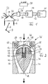
- FIG. 2 shows a longitudinal section through the additional control valve device 26 of FIG. 1.
- the through Arrows illustrating the air or fresh charge flow direction is from top to bottom in FIG. 2.
- the inlet channel 16 widens at the upstream end of the additional control valve device 26 by making the inner wall of the inlet duct body 30 conical expanding region 32.
- the extension area 32 goes in over a widest point a tapered area 34, which eventually smooth in the not shown to Inlet valve leading part of the inlet channel 16 passes.
- the flow body 36 is designed in accordance with the inner wall of the inlet channel body 30, so that an annular gap 40 with an annular gap between it and the inlet channel body 30 Flow cross section is formed.
- the flow cross section of the annular gap can be in the flow direction , as is known in hydraulic or aerodynamic devices, initially decrease and then slowly increase again.
- the flow body 36 has a blind hole 42 which is coaxial is formed with the axis A-A of the flow or the entire arrangement.
- the shaft 44 of an overall mushroom-shaped valve member 46 is guided in a blind hole, the hat 48 of the valve member 24 attached to the stem 44 shaped and the contours of the extension area 32 and the flow body 36 are adapted to it that the hat 48 in an upper, closed position according to FIG. 2, sealing on an inner valve seat 50 forming area of the extension area 32 and is flush in a lower open position runs with the outer contour of the flow body 36, which correspondingly excluded the hat 48 is.
- the hat 48 is on the side facing away from the inlet valve 20 convex with a vertex in the A-A axis.
- the shaft 44 ends in a collar 52. Between the collar 52 and the bottom of the blind hole 42 a first spring 54 is supported. Between the collar 52 and one at the top of the Blind spring 42 formed collar is supported by a further spring 56. That way it forms the valve member 46 together with the two springs 54 and 56 form an oscillatory system, which is held in a middle position by the springs.
- the natural frequency of the vibratory System is given by the spring constants and the weight of the valve member 46.
- the flow body 36 as a whole is for the ability to mount the valve member and the springs constructed in two parts, the upper part and the lower part with each other in any suitable manner are connectable.
- An annular electromagnet 58 is arranged in the upper part of the flow body 36 Pole surface is exposed and interacts with the hat 48 made of magnetic material.
- a further ring magnet 60 is located in the inlet channel body 30 in the region of the valve seat 50 arranged, the pole face also cooperates with the hat 48.
- the valve member 46 with the hat 48 When the ring magnet 58 is excited, the valve member 46 with the hat 48, if necessary supported by the air flow from the center position shown against the force of the spring 54 pulled into the open position, in which the hat 48 on the pole face of the ring magnet 58 is applied. If the ring magnet 58 is deactivated, the valve member oscillates under the influence of the Springs 54 and 56 in the direction of the closed position, in which there is a coordinated excitation of the Ring magnet 60 is held against the valve seat 50 by abutment of the hat 48. Will the magnet 60 deactivated, the valve member moves into the open position by the force of the springs, in which it is held by means of the magnet 58, etc.
- the natural frequency of the vibratable System is advantageously higher than the frequency with which the valve is actuated must, so that an extremely quick change between open and closed position is possible is, with only the holding force of the magnets and the kinetic Energy is stored in the springs.
- the respective contact surfaces can be designed accordingly, so that each time the system an air cushion has to be displaced.
- the auxiliary control valve When used for pulse charging for high torque even at low speeds the auxiliary control valve remains closed during the intake stroke with the intake valve open and is opened with the inlet valve still open when a high vacuum builds up Has. Fresh charge flows into the combustion chamber with high energy and correspondingly good filling, whose inlet valve is closed before backflow occurs. The additional valve is closed and is available for a new intake cycle. If the throttle valve is missing the additional control valve is actuated in coordination with the inlet valve such that only a predetermined small amount of fresh charge reaches the combustion chamber during an intake stroke.
- the angle that the valve seat forms with the central axis is on the seal and the flow matched and is for example at 45 °.
- the two ring magnets 58 and 60 have approximately the same radial Have diameters so that their pole faces are roughly opposite. It will be short Field lines are achieved in the anchor and a low anchor mass is possible. Through the nozzle or Diffuser flow in the annular gap 40 can be a targeted speed increase or deceleration can be achieved, which results in minimal flow losses.
- FIG. 3 shows an embodiment of an additional control valve device modified compared to FIG. 2 26, in which the collar 52 of the embodiment according to FIG. 2 is expanded to form an anchor plate 62 and the ring magnets 58 and 60 are received within the flow body 36. Otherwise, the function of the embodiment according to FIG. 3 corresponds to that of FIG. 2. Since the 3 does not define the closed position of the valve member 46 is that the hat 48 is held in direct contact with the valve seat 50 by magnetic force, but because the armature plate 62 is held by the ring magnet 60, it is advantageous to compensate for tolerances to make the hat 48 somewhat more elastic, which in turn it is possible that the hat 48 does not have to be made of magnetic material.
- the same advantages are achieved with the embodiment according to FIG. 3 as with that of FIG. 2. Because the angle of the valve seat 50 defines the angle at which the fresh charge flows into the annular gap 40, not be matched to magnetic holding forces must, but can mainly be determined from a flow point of view, the Angles should be slightly larger and be 50 degrees.
- FIG. 4 shows an embodiment of the additional control valve device which is modified compared to FIG. 3 26, the features of the embodiment according to FIG. 3 combined with those of FIG. 2 by in addition to the ring magnets 58 and 60 of FIG. 3 in the area of the valve seat 50 in the inlet channel body 30 an additional ring magnet 62 is arranged, which in this case also hat 48 consisting at least partially of magnetizable material directly in contact urges the valve seat 50.
- the ring magnet 60 serves to capture and hold the anchor plate 62 in the closed position.
- the additional ring magnet 62 is used to capture and hold the hat 48 in sealing system on valve seat 50.
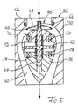
- Fig. 5 shows a further embodiment of an additional valve device, which compared to the Fig. 3 is modified.
- the hat 48 is movably guided on the shaft 44 and is made of two springs 66 and 68, which are opposed between the hat 48 and the Support shaft 44 pretensioned in a central position so that the hat with the springs is opposite the shaft forms an oscillatory system.
- a ring magnet 64 is arranged in the inlet channel body 30.
- Another ring magnet 70 is arranged in the flow body 36.
- the ring magnets 64 and 70 preferably form pure holding magnets for holding the hat 48 in its open or closed position while the magnets 58 and 60 form catch magnets for the anchor plate 62.
- the magnets 64 and 70 can be dimensioned weaker.
- the advantage becomes shorter Switching times between open and closed position of the valve achieved. Assume that The valve is in the closed position, i.e. the hat 48 in contact with the excited ring magnet 64 and the armature plate 62 in contact with the excited ring magnet 60. When the valve is then switched should be deactivated, the magnet 60 is deactivated and the magnet 58 is activated, so that the Anchor plate 62 moves under the action of springs 52, 54 in contact with the ring magnet 58 and is held there.
- the holding magnet 64 initially remains excited, so that the hat 48 in the closed position remains, whereby the shaft 44 deforms relative to the hat 48 while the springs 66, 68 are deformed gem. Fig. 5 moved down. If the magnet 64 then, for example, just before the anchor plate reaches its lower position, deactivated, that of the springs 66 and 68 moves biased hat 48 accelerates into contact with the magnet 70 and is in the open position held.
- the effective switching time of the valve which is given by the time period by the Hat to move from the closed to the open position and vice versa is shortened, which reduces charge exchange losses and enables more precise control is.
- the additional control valve device described can be modified in a variety of ways:
- Fig. 5 as well the holding magnet 64 of FIG. 4 can be formed by permanent magnets whose strength is based on the springs and the catch magnets are matched so that the holding magnets the movement of the Release hats 48 in a suitable manner.
- the valve member does not necessarily have to be a component of an oscillatory system.
- the valve member can be actuated hydraulically, pneumatically or in some other way, for example by holding the brackets 38 (FIG. 2) corresponding supply lines have been made.
- the bottom of the blind hole 42 can in be vented in a variety of ways and the shaft can correspond to the blind hole stepped cross sections can be formed so that the movement of the valve member in can dampen in various ways before reaching the open or closed position.
- the 5 can also be used without the magnets 64 and 70 for tolerance compensation become.
Landscapes
- Engineering & Computer Science (AREA)
- Chemical & Material Sciences (AREA)
- Combustion & Propulsion (AREA)
- Mechanical Engineering (AREA)
- General Engineering & Computer Science (AREA)
- Magnetically Actuated Valves (AREA)
- Characterised By The Charging Evacuation (AREA)
- Lift Valve (AREA)
Abstract
Description
Die Erfindung betrifft eine in einem Einlasskanal einer Kolbenbrennkraftmaschine angeordnete Zusatzsteuerventileinrichtung.The invention relates to one arranged in an inlet duct of a piston internal combustion engine Additional control valve device.
Aus der DE 199 08 435 ist eine in einem Einlasskanal einer Kolbenbrennkraftmaschine angeordnete Zusatzsteuerventileinrichtung bekannt, die zur Impulsaufladung der Brennkraftmaschine verwendet wird. Bei einer solchen Impulsaufladung bleibt die stromoberhalb eines herkömmlichen Einlassventils der Brennkraftmaschine angeordnete Zusatzsteuerventileinrichtung während des Ansaughubs des Kolbens bei offenem Einlassventil dicht geschlossen, so dass sich stromabwärts des Zusatzventils ein hoher Unterdruck aufbaut. Wird das Zusatzventil dann geöffnet, so erhält die einströmende Frischladung aufgrund des Unterdrucks einen hohen Impuls, wodurch die Füllung des Brennraums erhöht wird und ein größeres Drehmoment erzielbar ist als ohne Impulsaufladung.From DE 199 08 435 one is arranged in an inlet channel of a piston internal combustion engine Additional control valve device known for pulse charging the internal combustion engine is used. With such a pulse charging, the current remains above a conventional one Inlet valve of the internal combustion engine arranged additional control valve device during of the piston suction stroke with the intake valve open tightly closed so that it is downstream of the additional valve builds up a high vacuum. If the additional valve is then opened, so the incoming fresh charge receives a high impulse due to the negative pressure, thereby the filling of the combustion chamber is increased and a greater torque can be achieved than without Pulse charging.
In der DE 43 14 809 A1,von der im Oberbegriff des Hauptanspruchs der vorliegenden Anmeldung ausgegangen wird, ist ein im Einlasskanal angeordnetes Rückschlagventil beschrieben, das erforderlichenfalls auch mit Fremdkraft betätigt werden kann. Das Ventilglied ist beispielsweise ein im Querschnitt dreieckiger Dichtkörper, der über einen Schaft an einer im Einlasskanal vorgesehenenalterung beweglich geführt ist. Es kann lediglich durch Differenzdruck betätigt werden oder beispielsweise mittels einer Stelleinrichtung, beispielsweise einem Servomotor. Die Stelleinrichtung kann ein mechanisches Gestänge aufweisen, das von außen in den Einlasskanal einragt. Das Ventilglied kann als ein Kegelstumpf ausgebildet sein, dessen abgeflachte Spitze eingezogen ist. Das Ventilglied kann mittels eines Elektromagneten oder einer Gasfeder betätigt werden. Eine Eigenart der Ventile gemäß der vorgenannten Druckschrift liegt darin, dass sie zu deutlichen Wirbelbildungen führen und den Strömungswiderstand der Strömung durch den Einlasskanal vergrößern. In DE 43 14 809 A1, in the preamble of the main claim of the present application is assumed, a check valve arranged in the inlet duct is described, the if necessary, can also be operated with external power. The valve member is, for example a sealing body which is triangular in cross section and which is connected via a shaft to a bracket provided in the inlet duct is movably guided. It can only be operated by differential pressure or for example by means of an actuator, for example a servo motor. The actuator can have a mechanical linkage that extends from the outside into the inlet duct protrudes. The valve member can be designed as a truncated cone, the flattened tip has moved in. The valve member can be actuated by means of an electromagnet or a gas spring become. A peculiarity of the valves according to the aforementioned document is that they are too significant vortex formation and the flow resistance of the flow through the inlet channel enlarge.
Die DE 611 659 C1 zeigt einen in einem Schalldämpfer angeordneten stromlinienförmigen Drehkörper, durch dessen Gesamtverschiebung der Durchschnittsquerschnitt eines Ringspaltes veränderbar ist.DE 611 659 C1 shows a streamlined arrangement arranged in a silencer Rotary body, through the total displacement of which the average cross-section of an annular gap is changeable.
Der Erfindung liegt die Aufgabe zugrunde, eine in einem Einlaßkanal einer Kolbenbrennkraftmaschine angeordnete Zusatzsteuerventileinrichtung zu schaffen, mit der bei einfachem Aufbau die aus der Praxis gestellten Forderungen hinsichtlich geringer Beeinflussung des Strömungswiderstandes und rascher und mit dem Verbrauch von nur wenig Energie verbundener Betätigbarkeit erfüllt werden.The invention has for its object one in an inlet channel of a piston internal combustion engine arranged additional control valve device to create, with the simple structure the demands made in practice with regard to low influence on the flow resistance and quicker and operable with little energy consumption be fulfilled.
Diese Aufgabe wird mit den Merkmalen des Anspruchs 1 gelöst.This object is achieved with the features of claim 1.
In seiner Offenstellung bewirkt das Zusatzsteuerventil praktisch keine Erhöhung des Strömungswiderstandes des Einlasskanals, da die Oberfläche des Ventilgliedes in dessen Offenstellung bündig mit der restlichen Oberfläche des Strömungskörpers verläuft.In its open position, the additional control valve causes practically no increase in flow resistance of the inlet channel, since the surface of the valve member is in its open position runs flush with the remaining surface of the flow body.
Mit den Merkmalen des Anspruchs 2 wird der Strömungskörper in vorteilhafter Weise weitergebildet.With the features of
Mit den Merkmalen des Anspruchs 3 wird erreicht, dass die Zusatzsteuerventileinrichtung in
einfacher Weise im Einlasskanal untergebracht werden kann, wobei zur Betätigung des Ventilgliedes
lediglich ein elektrischer oder ggf. pneumatischer oder hydraulischer Anschluß an den
Strömungskörper erforderlich ist.It is achieved with the features of
Mit den Merkmalen des Anspruchs 4 wird eine sehr rasche und energetisch günstige Betätigbarkeit
des Ventilglieds erreicht.With the features of
Die Ansprüche 5 bis 12 kennzeichnen vorteilhafte Ausführungsformen und Weiterbildungen der erfindungsgemäßen Zusatzsteuerventileinrichtung.Claims 5 to 12 characterize advantageous embodiments and developments of the additional control valve device according to the invention.
Die erfindungsgemäße Zusatzsteuerventileinrichtung kann sowohl zur Impulsaufladung verwendet werden als auch derart ausgebildet werden, dass bei Ottomotoren ein Betrieb ohne Drosselklappe möglich ist. Weiter sind mit der Zusatzsteuerventileinrichtung zusätzliche Freiheitsgrade bezüglich anderer Arten der Ladungswechselsteuerung gegeben. The additional control valve device according to the invention can be used both for pulse charging will also be designed in such a way that gasoline engines can operate without a throttle valve is possible. Furthermore, additional degrees of freedom are available with the additional control valve device given with regard to other types of charge control.
Die Erfindung wird im folgenden anhand schematischer Zeichnungen beispielsweise und mit weiteren Einzelheiten erläutert.The invention is described below with reference to schematic drawings, for example and with explained further details.
Es stellen dar:
Gemäß Fig. 1 weist eine Hubkolbenbrennkraftmaschine mehrere Zylinder 2 auf, in denen je ein
Kolben 4 arbeitet, der über ein Pleuel 6 mit einer Kurbelwelle 8 verbunden ist. Die Frischluft-
bzw. Frischladungszufuhr zu dem Zylinder 2 erfolgt durch ein Luftfilter 10 hindurch, das über
eine Zufuhrleitung 12 mit einem Luftsammler 14 verbunden ist, von dem aus einzelne, jeweils
einen Einlasskanal 16 bildende Schwingrohre in den Brennraum 18 des Zylinders 2 führen. In
der Mündung jedes Schwingrohres bzw. Einlasskanals 16 in den Brennraum 18 ist wenigstens
ein Einlassventil 20 angeordnet. In der Öffnung des Brennraums in einen Auslasskanal 22 hinein
arbeitet wenigstens ein Auslassventil 24. Die Ausbildung des Ansaugsystems mit Schwingrohren
ist vorteilhaft, jedoch nicht zwingend.1, a reciprocating piston internal combustion engine has a plurality of
In dem Einlasskanal 16 ist stromoberhalb des Einlassventils 20 eine Zusatzsteuerventileinrichtung
26 vorgesehen, deren Zusatzsteuerventil von einem Steuergerät 28 gesteuert wird.An additional control valve device is located in the
Die Wirkungsweise der beschriebenen Anordnung einschließlich der Gemischaulbereitung, usw., ist an sich bekannt und wird daher nicht im einzelnen erläutert. The mode of operation of the described arrangement including the mixture preparation, etc., is known per se and is therefore not explained in detail.
Fig. 2 zeigt einen Längsschnitt durch die Zusatzsteuerventileinrichtung 26 der Fig. 1. Die durch
Pfeile verdeutlichte Luft- bzw. Frischladungsströmungsrichtung ist in Fig. 2 von oben nach unten.FIG. 2 shows a longitudinal section through the additional
Wie ersichtlich, erweitert sich der Einlasskanal 16 am strömungsaufwärtigen Ende der Zusatzsteuerventileinrichtung
26, indem die Innenwand des Einlasskanalkörpers 30 einen sich konisch
erweiternden Bereich 32 aufweist. Der Erweiterungsbereich 32 geht über eine breiteste Stelle in
einen sich verjüngenden Bereich 34 über, der schließlich glatt in den nicht dargestellten zum
Einlassventil führenden Teil des Einlasskanals 16 übergeht.As can be seen, the
In dem Erweiterungsbereich 22 und dem sich anschließenden Verjüngungsbereich 34 ist ein insgesamt
stromlinienförmiger Strömungskörper 36 angeordnet, der mittels Halterungen 38, die
ebenfalls strömungsgünstig ausgebildet sind, in dem Einlasskanalkörper 30 gehalten ist.In the
Der Strömungskörper 36 ist der Innenwandung des Einlasskanalkörpers 30 entsprechend ausgebildet,
so dass zwischen ihm und dem Einlasskanalkörper 30 ein Ringspalt 40 mit ringförmigem
Durchströmquerschnitt gebildet ist. Der Strömungsquerschnitt des Ringspaltes kann in Strömungsrichtung
, wie bei hydraulischen oder aerodynamischen Einrichtungen bekannt, zunächst
abnehmen und dann langsam wieder zunehmen.The
An seinem stromaufwärtigen Ende weist der Strömungskörper 36 ein Sackloch 42 auf, das koaxial
mit der Achse A-A der Strömung bzw. der gesamten Anordnung ausgebildet ist. In dem
Sackloch ist der Schaft 44 eines insgesamt pilzförmigen Ventilgliedes 46 beweglich geführt,
wobei der am Schaft 44 befestigte Hut 48 des Ventilglieds 24 derart geformt und die Konturen
des Erweiterungsbereiches 32 und des Strömungskörpers 36 an ihn angepasst sind, dass der Hut
48 in einer gemäß Fig. 2 oberen Schließstellung dichtend an einem inneren, einen Ventilsitz 50
bildenden Bereich des Erweiterungsbereiches 32 anliegt und in einer unteren Offenstellung bündig
mit der Außenkontur des Strömungskörpers 36 verläuft, der dem Hut 48 entsprechend ausgenommen
ist. Wie ersichtlich, ist der Hut 48 zu der vom Einlassventil 20 abgewandten Seite hin
konvex mit einem Scheitelpunkt in der Achse A-A.At its upstream end, the
Der Schaft 44 endet in einem Bund 52. Zwischen dem Bund 52 und dem Boden des Sackloches
42 stützt sich eine erste Feder 54 ab. Zwischen dem Bund 52 und einem am oberen Ende des
Sackloches 42 ausgebildeten Bund stützt sich eine weitere Feder 56 ab. Auf diese Weise bildet
das Ventilglied 46 zusammen mit den beiden Federn 54 und 56 ein schwingungsfähiges System,
welches von den Federn in einer Mittellage gehalten wird. Die Eigenfrequenz des schwingungsfähigen
Systems ist durch die Federkonstanten und das Gewicht des Ventilgliedes 46 gegeben.The
Zur Montierbarkeit des Ventilgliedes und der Federn ist der Strömungskörper 36 insgesamt
zweiteilig aufgebaut, wobei der Oberteil und der Unterteil auf jedwelche geeignete Weise miteinander
verbindbar sind.The
Im Oberteil des Strömungskörpers 36 ist ein ringförmiger Elektromagnet 58 angeordnet, dessen
Polfläche frei liegt und mit dem aus magnetischem Material bestehenden Hut 48 zusammenwirkt.
Im Einlasskanalkörper 30 ist im Bereich des Ventilsitzes 50 ein weiterer Ringmagnet 60
angeordnet, dessen Polfläche ebenfalls mit dem Hut 48 zusammenwirkt. Die elektrischen Anschlussleitungen
der Ringmagnete 58 und 60, die mit dem Steuergerät 28 verbunden sind, sind
nicht dargestellt.An
Die Funktion der beschriebenen Zusatzsteuerventileinrichtung 26 ist folgende:The function of the additional
Bei Erregung des Ringmagneten 58 wird das Ventilglied 46 mit dem Hut 48, gegebenenfalls
unterstützt durch die Luftströmung, aus der dargestellten Mittelstellung gegen die Kraft der Feder
54 in die Offenstellung gezogen, in der der Hut 48 an der Polfläche des Ringmagneten 58
anliegt. Wird der Ringmagnet 58 deaktiviert, so schwingt das Ventilglied unter dem Einfluss der
Federn 54 und 56 in Richtung auf die Schließstellung, in der es durch abgestimmte Erregung des
Ringmagneten 60 unter Anlage des Hutes 48 an dem Ventilsitz 50 gehalten wird. Wird der Magnet
60 deaktiviert, so bewegt sich das Ventilglied durch die Kraft der Federn in die Offenstellung,
in der es mit Hilfe des Magneten 58 gehalten wird, usw.. Die Eigenfrequenz des schwingfähigen
Systems ist vorteilhafterweise höher als die Frequenz, mit der das Ventil betätigt werden
muss, so dass ein außerordentlich rascher Wechsel zwischen Offen- und Schließstellung möglich
ist, wobei von den Magneten jeweils nur die Haltekraft aufgebracht werden muss und die kinetische
Energie in den Federn gespeichert wird.When the
Zur Dämpfung der Auftreffbewegung des Hutes auf den Strömungskörper 36 und den Ventilsitz
können die jeweiligen Anlageflächen entsprechend ausgebildet sein, so dass bei der Anlage jeweils
ein Luftpolster verdrängt werden muss. To dampen the impact movement of the hat on the
Bei Verwendung zur Impulsaufladung für ein hohes Drehmoment bereits bei niedrigen Drehzahlen bleibt das Zusatzsteuerventil während des Ansaughubs bei offenem Einlassventil geschlossen und wird bei weiterhin offenem Einlassventil geöffnet, wenn sich ein hoher Unterdruck aufgebaut hat. Frischladung strömt mit hoher Energie und entsprechend guter Füllung in den Brennraum, dessen Einlassventil geschlossen wird, bevor eine Rückströmung entsteht. Das Zusatzventil wird geschlossen und steht für einen neuen Ansaugzyklus zur Verfügung. Bei fehlender Drosselklappe wird das Zusatzsteuerventil in Abstimmung mit dem Einlassventil derart betätigt, dass bei einem Ansaughub nur eine vorbestimmte kleine Menge Frischladung in den Brennraum gelangt.When used for pulse charging for high torque even at low speeds the auxiliary control valve remains closed during the intake stroke with the intake valve open and is opened with the inlet valve still open when a high vacuum builds up Has. Fresh charge flows into the combustion chamber with high energy and correspondingly good filling, whose inlet valve is closed before backflow occurs. The additional valve is closed and is available for a new intake cycle. If the throttle valve is missing the additional control valve is actuated in coordination with the inlet valve such that only a predetermined small amount of fresh charge reaches the combustion chamber during an intake stroke.
Die erfindungsgemäße Zusatzsteuerventileinrichtung hat zahlreiche Vorteile:
- Sie ist insgesamt rotationssymmetrisch aufgebaut, was die Produktionskosten vermindert.
- Sie ist strömungsgünstig, wodurch kaum Strömungs- oder Wirbelverluste entstehen, wodurch der Wirkungsgrad einer Impulsaufladung entscheidend verbessert wird.
- Sie benötigt nur wenig elektrische Energie, da die jeweils erforderliche kinetische Energie in den Federn gespeichert wird. Die Öffnung des Ventils ist außerordentlich rasch, da sie durch den Unterdruck bzw. die dann einsetzende Strömung unterstützt wird.
- In Schließstellung wird eine zuverlässige gasdichte Abdichtung erreicht.
- Die Ruhe- bzw. Mittelstellung kann in einfacher Weise dadurch verändert werden, dass der
Fußpunkt der Feder 54 mittels einer nicht dargestellten, in
den Strömungskörper 36 eingeschraubten Einstellschraube verändert wird. - Das insgesamt einen Anker bildende Ventilglied kann bei minimaler Masse mit guten magnetischen
Eigenschaften ausgebildet werden, indem für
den Hut 48 radial unterschiedliche Wandstärken mit Verdickung im magnetischen Wirkbereich und Verjüngung im nichtmagnetischen Bereich verwendet werden. Weiter ist es möglich, einen magnetischen Werkstoff im magnetischen Wirkbereich mit einem mechanisch hochfesten Werkstoff, beispielsweise einem Verbundwerkstoff, mit niedriger spezifischer Masse zu verbinden. - Durch die glockenförmige Ausbildung des Hutes weist dieser eine hohe Strukturfestigkeit bei gleichzeitig günstiger Strömungsform auf. Durch den hutförmigen Anker weist der Anker eine gewisse Elastizität auf, wobei die Führung des Schaftes 44 zusätzlich ein gewisses Spiel aufweisen kann, so dass das Ventilglied selbst zentrierend ist, Toleranzen ausgeglichen werden und niedrige Auftreffgeräusche entstehen.
- Die beschriebene Zusatzsteuerventileinrichtung ist als Modul herstellbar und in vorhandene Einlasskanäle in einfacher Weise nachrüstbar.
- Infolge der raschen Ansteuerbarkeit des Ventilgliedes ist es möglich, die erfindungsgemäße Zusatzsteuerventileinrichtung nicht nur für eine Impulsaufladung zu verwenden, sondern auch anstelle einer Drosselklappe einzusetzen, wodurch Kosten gespart werden und Verbrauchsreduzierungen möglich sind.
- Overall, it has a rotationally symmetrical structure, which reduces the production costs.
- It is aerodynamically favorable, so that hardly any flow or vortex losses occur, which significantly improves the efficiency of pulse charging.
- It requires little electrical energy because the required kinetic energy is stored in the springs. The opening of the valve is extremely quick, since it is supported by the negative pressure or the flow that then begins.
- A reliable gas-tight seal is achieved in the closed position.
- The rest or middle position can be changed in a simple manner by changing the base point of the
spring 54 by means of an adjusting screw (not shown) screwed into theflow body 36. - The valve member, which forms an armature overall, can be designed with minimal magnetic properties and good magnetic properties by using radially different wall thicknesses with thickening in the magnetic effective range and tapering in the non-magnetic range for the
hat 48. It is also possible to combine a magnetic material in the magnetic effective range with a mechanically high-strength material, for example a composite material, with a low specific mass. - Due to the bell-shaped design of the hat, it has a high structural strength with a favorable flow shape. Due to the hat-shaped anchor, the anchor has a certain elasticity, and the guide of the
shaft 44 can additionally have a certain play, so that the valve member is centering itself, tolerances are compensated for and low impact noises occur. - The described additional control valve device can be produced as a module and can be easily retrofitted into existing inlet channels.
- As a result of the rapid controllability of the valve member, it is possible not only to use the additional control valve device according to the invention for pulse charging, but also to use it instead of a throttle valve, thereby saving costs and reducing consumption.
Der Winkel, den der Ventilsitz mit der Mittelachse bildet, ist auf die Abdichtung und die Strömung abgestimmt und liegt beispielsweise bei 45°.The angle that the valve seat forms with the central axis is on the seal and the flow matched and is for example at 45 °.
Vorteilhaft ist weiter, wenn die beiden Ringmagnete 58 und 60 annähernd gleiche radiale
Durchmesser haben, so dass sich deren Polflächen etwa gegenüber liegen. Damit werden kurze
Feldlinien im Anker erzielt und es ist eine geringe Ankermasse möglich. Durch die Düsen- bzw.
Diffusorströmung im Ringspalt 40 kann eine gezielte Geschwindigkeitsüberhöhung bzw. -verzögerung
erzielt werden, wodurch insgesamt minimale Strömungsverluste entstehen.It is also advantageous if the two
Fig. 3 zeigt eine gegenüber Fig. 2 abgeänderte Ausführungsform einer Zusatzsteuerventileinrichtung
26, bei der der Bund 52 der Ausführungsform gemäß Fig. 2 zu einer Ankerplatte 62 erweitert
ist und die Ringmagneten 58 und 60 innerhalb des Strömungskörpers 36 aufgenommen sind.
Ansonsten entspricht die Funktion der Ausführungsform gemäß Fig. 3 der der Fig. 2. Da bei der
Ausführungsform gemäß Fig. 3 die Schließstellung des Ventilglieds 46 nicht dadurch definiert
ist, dass der Hut 48 unmittelbar durch Magnetkraft in Anlage an dem Ventilsitz 50 gehalten ist,
sondern dadurch, dass die Ankerplatte 62 von dem Ringmagneten 60 gehalten wird, ist es vorteilhaft,
zum Ausgleich von Toleranzen den Hut 48 etwas elastischer auszubilden, was dadurch
möglich ist, dass der Hut 48 nicht aus magnetischem Material bestehen muss.FIG. 3 shows an embodiment of an additional control valve device modified compared to FIG. 2
26, in which the
Ansonsten werden mit der Ausführungsform gemäß Fig. 3 die gleichen Vorteile erzielt wie mit
der der Fig. 2. Da der Winkel des Ventilsitzes 50, der den Winkel definiert, unter dem die Frischladung
in den Ringspalt 40 einströmt, nicht auf magnetische Haltekräfte abgestimmt werden
muss, sondern vorwiegend unter Strömungsgesichtspunkten festgelegt werden kann, kann der
Winkel etwas größer sein und 50 Grad betragen.Otherwise, the same advantages are achieved with the embodiment according to FIG. 3 as with
that of FIG. 2. Because the angle of the
Fig. 4 zeigt eine gegenüber Fig. 3 abgeänderte Ausführungsform der Zusatzsteuerventileinrichtung
26, die Merkmale der Ausführungsform gemäß Fig. 3 mit denen der Fig. 2 vereint, indem
zusätzlich zu den Ringmagneten 58 und 60 der Fig. 3 im Bereich des Ventilsitzes 50 im Einlasskanalkörper
30 ein zusätzlicher Ringmagnet 62 angeordnet ist, der den in diesem Fall ebenfalls
zumindest teilweise aus magnetisierbarem Material bestehenden Hut 48 unmittelbar in Anlage an
den Ventilsitz 50 drängt. Der Ringmagnet 60 dient zum Einfangen und Halten der Ankerplatte
62 in Schließstellung. Der zusätzliche Ringmagnet 62 dient zum Einfangen und Halten des Hutes
48 in dichtender Anlage am Ventilsitz 50.FIG. 4 shows an embodiment of the additional control valve device which is modified compared to FIG. 3
26, the features of the embodiment according to FIG. 3 combined with those of FIG. 2 by
in addition to the
Fig. 5 zeigt eine weitere Ausführungsform einer Zusatzventileinrichtung, die gegenüber der der
Fig. 3 abgeändert ist. Bei dieser Ausführungsform ist der Hut 48 beweglich am Schaft 44 geführt
und wird von zwei Federn 66 und 68, die sich gegensinnig zwischen dem Hut 48 und dem
Schaft 44 abstützen in eine Mittelstellung vorgespannt, sodass der Hut mit den Federn ein gegenüber
dem Schaft schwingungsfähiges System bildet. Ähnlich wie der Ringmagnet 64 der Fig.
4 ist im Einlasskanalkörper 30 ein Ringmagnet 64 angeordnet. Ein weiterer Ringmagnet 70 ist
im Strömungskörper 36 angeordnet. Die Ringmagnete 64 und 70 bilden bevorzugt reine Haltemagnete
zum Halten des Hutes 48 in dessen Offen- oder Schließstellung, während die Magnete
58 und 60 Fangmagnete für die Ankerplatte 62 bilden. Entsprechend können die Magnete 64 und
70 schwächer dimensioniert werden. Mit der Ausführungsform gem. Fig. 5 wird der Vorteil kürzerer
Schaltzeiten zwischen Offen- und Schließstellung des Ventils erzielt. Sei angenommen, das
Ventil befinde sich in Schließstellung, d.h. der Hut 48 in Anlage am erregten Ringmagneten 64
und die Ankerplatte 62 in Anlage am erregten Ringmagneten 60. Wenn das Ventil dann umgeschaltet
werden soll, wird der Magnet 60 deaktiviert und der Magnet 58 aktiviert, sodass sich die
Ankerplatte 62 unter Wirkung der Federn 52, 54 in Anlage an den Ringmagneten 58 bewegt und
dort gehalten wird. Der Haltemagnet 64 bleibt zunächst erregt, sodass der Hut 48 in Schließstellung
bleibt, wobei sich der Schaft 44 unter Verformung der Federn 66, 68 relativ zum Hut 48
gem. Fig. 5 nach unten bewegt. Wird der Magnet 64 dann, beispielsweise kurz bevor die Ankerplatte
ihre untere Position erreicht, deaktiviert, so bewegt sich der von den Federn 66 und 68
vorgespannte Hut 48 beschleunigt in Anlage an den Magneten 70 und wird in Offenstellung
gehalten. Die effektive Schaltdauer des Ventils, die durch die Zeitdauer gegeben ist, die von dem
Hut zur Bewegung von der Schließ- in die Offenstellung und umgekehrt benötigt wird, ist verkürzt,
wodurch Ladungswechselverluste vermindert sind und eine präzisere Steuerung möglich
ist. Durch die gegenüber der Deaktivierung des jeweiligen Fangmagneten 60 bzw. 58 verzögerte
Deaktivierung des jeweiligen Haltemagneten 64 bzw. 70 wird im Schwingsystem 48, 66, 68
Energie gespeichert, die dann für eine beschleunigte Bewegung des Hutes genutzt wird. Es verstejt
sich, dass die Mittelstellung des Hutes vorteilhafterweise derart auf die Stellungen der Ankerplatte
abgestimmt ist, dass der Hut auch ohne Aktivierung der Magnete 64, 70 in sicherer
Anlage an deren Polflächen bzw. in Schließ- oder Offenstellung ist.Fig. 5 shows a further embodiment of an additional valve device, which compared to the
Fig. 3 is modified. In this embodiment, the
Die geschilderte Zusatzsteuerventileinrichtung kann in vielfältiger Weise abgeändert werden:
Die als Haltemagnete wirksamen Magnete 64 und 70 der Ausführungsform gem. Fig. 5 sowie
der Haltemagnet 64 der Fig. 4 können durch Permanentmagnete gebildet sein, deren Stärke auf
die Federn und die Fangmagnete abgestimmt ist, sodass die Haltemagnete die Bewegung des
Hutes 48 jeweils in geeigneter Weise freigeben. Das Ventilglied muss nicht zwingend Bestandteil
eines schwingfähigen Systems sein. Die Betätigung des Ventilgliedes kann hydraulisch,
pneumatisch oder sonstwie erfolgen, indem beispielsweise durch die Halterungen 38 (Fig. 2)
entsprechende Zuleitungen durchgeführt sind. Der Boden des Sackloches 42 kann in
unterschiedlichster Weise entlüftet sein und der Schaft kann entsprechend dem Sackloch mit
abgestuften Querschnitten ausgebildet sein, so dass sich die Bewegung des Ventilglieds in
unterschiedlichster Weise vor dem Erreichen der Offen- oder Schließstellung dämpfen läßt. Die
Anordnung der Fig. 5 kann auch ohne die Magnete 64 und 70 zum Toleranzausgleich verwendet
werden. Merkmale der verschiedenen Ausführungsformen können in unterschiedlicher Weise
miteinander kombiniert werden.The additional control valve device described can be modified in a variety of ways:
The
Claims (12)
der Körper als stromlinienförmiger Strömungskörper (36) ausgebildet ist, dessen Querschnitt auf dem des sich erweiternden und sich verjüngenden Bereiches (32, 34) derart abgestimmt ist, daß der ringförmige Durchströmquerschnitt sich in Strömungsrichtung nicht sprunghaft ändert und daß das Ventilglied (46) in Offenstellung bündig mit der Oberfläche des Strömungskörpers verläuft.Auxiliary control valve device arranged in an inlet channel of a piston internal combustion engine, comprising:
the body is designed as a streamlined flow body (36), the cross section of which is coordinated with that of the widening and tapering region (32, 34) in such a way that the annular flow cross section does not change abruptly in the direction of flow and that the valve member (46) is in the open position runs flush with the surface of the flow body.
Applications Claiming Priority (2)
| Application Number | Priority Date | Filing Date | Title |
|---|---|---|---|
| DE10137828A DE10137828B4 (en) | 2001-08-02 | 2001-08-02 | Additional control valve device arranged in an intake passage of a reciprocating internal combustion engine |
| DE10137828 | 2001-08-02 |
Publications (3)
| Publication Number | Publication Date |
|---|---|
| EP1281845A2 true EP1281845A2 (en) | 2003-02-05 |
| EP1281845A3 EP1281845A3 (en) | 2004-01-07 |
| EP1281845B1 EP1281845B1 (en) | 2007-02-21 |
Family
ID=7694086
Family Applications (1)
| Application Number | Title | Priority Date | Filing Date |
|---|---|---|---|
| EP02015862A Expired - Lifetime EP1281845B1 (en) | 2001-08-02 | 2002-07-16 | Additional control valve in the intake pipe of an internal combustion engine |
Country Status (4)
| Country | Link |
|---|---|
| US (1) | US6637405B2 (en) |
| EP (1) | EP1281845B1 (en) |
| AT (1) | ATE354723T1 (en) |
| DE (2) | DE10137828B4 (en) |
Cited By (2)
| Publication number | Priority date | Publication date | Assignee | Title |
|---|---|---|---|---|
| WO2010057726A1 (en) * | 2008-11-21 | 2010-05-27 | Robert Bosch Gmbh | Gas feeding module |
| WO2012052260A1 (en) * | 2010-10-18 | 2012-04-26 | Robert Bosch Gmbh | Throttle device |
Families Citing this family (20)
| Publication number | Priority date | Publication date | Assignee | Title |
|---|---|---|---|---|
| DE10207658B4 (en) * | 2002-02-22 | 2008-09-04 | Meta Motoren- Und Energie-Technik Gmbh | Method for shortening the opening and closing edge of a valve, as well as valve |
| US7004120B2 (en) * | 2003-05-09 | 2006-02-28 | Warren James C | Opposed piston engine |
| US6969048B2 (en) | 2003-06-17 | 2005-11-29 | Siemens Aktiengesellschaft | Valve element for supplementary control valve device |
| DE10327271A1 (en) * | 2003-06-17 | 2005-02-24 | Siemens Ag | Valve member for an additional control valve device |
| DE10329400A1 (en) | 2003-06-30 | 2005-02-03 | Siemens Ag | Additional control valve device for an intake port of a reciprocating internal combustion engine |
| DE10331689B4 (en) * | 2003-07-14 | 2010-04-22 | Audi Ag | air intake duct |
| DE10332440A1 (en) | 2003-07-16 | 2005-02-17 | Siemens Ag | Additional control valve device for an intake port of a reciprocating internal combustion engine |
| DE10335128A1 (en) * | 2003-07-31 | 2005-02-24 | Siemens Ag | Method for producing a valve disk of a valve member of an additional control valve device |
| DE10335136A1 (en) * | 2003-07-31 | 2005-02-17 | Siemens Ag | Subunit for an additional control valve device for an inlet channel of a piston internal combustion engine |
| DE10335121A1 (en) | 2003-07-31 | 2005-02-24 | Siemens Ag | Method for arranging a valve member in an additional control valve device |
| DE10346005B4 (en) | 2003-10-02 | 2006-04-13 | Siemens Ag | Air intake module for an internal combustion engine with impulse charging |
| DE10347444B4 (en) * | 2003-10-13 | 2014-10-30 | Audi Ag | Device for pulse charging |
| DE102005039368B9 (en) | 2005-08-08 | 2007-11-08 | Meta Motoren- Und Energie-Technik Gmbh | Switchable valve actuation mechanism |
| DE102005052423B4 (en) * | 2005-11-03 | 2016-12-29 | Robert Bosch Gmbh | Apparatus for pulse charging an internal combustion engine |
| US7513235B2 (en) * | 2006-02-13 | 2009-04-07 | Gm Global Technology Operations, Inc. | Method and apparatus for operating impulse charger for transient torque management |
| DE102006023853A1 (en) * | 2006-05-19 | 2007-11-22 | Mahle International Gmbh | Method for controlling an internal combustion engine |
| JP2009144699A (en) * | 2007-12-14 | 2009-07-02 | Hyundai Motor Co Ltd | Impulse charger for vehicle engine |
| ATE535692T1 (en) * | 2007-12-21 | 2011-12-15 | Hong Kong Meta Company Ltd | METHOD FOR OPERATING AN INTERNAL COMBUSTION ENGINE AND INTERNAL COMBUSTION ENGINE |
| WO2015092451A1 (en) * | 2013-12-20 | 2015-06-25 | Pakai Tibor | Device and procedure for increasing the efficiency of internal combustion engines |
| WO2019169365A1 (en) * | 2018-03-02 | 2019-09-06 | S.P.M. Flow Control, Inc. | Novel valve having spherical sealing surface |
Citations (3)
| Publication number | Priority date | Publication date | Assignee | Title |
|---|---|---|---|---|
| DE611659C (en) | 1935-04-02 | Johannes Woerner | Silencer for internal combustion engines in which the cross section of the exhaust gas outlet can be changed | |
| DE4314809A1 (en) | 1993-05-05 | 1994-11-10 | Freudenberg Carl Fa | Intake pipe for an internal combustion engine |
| DE19908435A1 (en) | 1999-02-26 | 2000-09-07 | Meta Motoren Energietech | Method and device for pulse charging a piston internal combustion engine |
Family Cites Families (7)
| Publication number | Priority date | Publication date | Assignee | Title |
|---|---|---|---|---|
| GB430164A (en) * | 1933-12-09 | 1935-06-11 | Harold Henry Platts | Improvements in fluid operated streamline valves for flow or pressure control |
| FR1015012A (en) * | 1949-03-29 | 1952-08-26 | Method and device for regulating fluids in conduits | |
| US2809660A (en) * | 1956-04-24 | 1957-10-15 | Aeroquip Corp | Cushioned streamlined check valve |
| US3119405A (en) * | 1961-06-12 | 1964-01-28 | Rotax Ltd | Compressed air or other gas control valves |
| US4412517A (en) * | 1980-10-06 | 1983-11-01 | Toyota Jidosha Kogyo Kabushiki Kaisha | Idling speed control device of an internal combustion engine |
| US5415142A (en) * | 1993-02-23 | 1995-05-16 | Mitsubishi Denki Kabushiki Kaisha | Control method and apparatus for internal combustion engine |
| US5666913A (en) * | 1996-05-29 | 1997-09-16 | Cummins Engine Company, Inc. | Variable timing cam follower lever assembly |
-
2001
- 2001-08-02 DE DE10137828A patent/DE10137828B4/en not_active Expired - Fee Related
-
2002
- 2002-07-16 DE DE50209519T patent/DE50209519D1/en not_active Expired - Lifetime
- 2002-07-16 EP EP02015862A patent/EP1281845B1/en not_active Expired - Lifetime
- 2002-07-16 AT AT02015862T patent/ATE354723T1/en not_active IP Right Cessation
- 2002-08-02 US US10/212,372 patent/US6637405B2/en not_active Expired - Fee Related
Patent Citations (3)
| Publication number | Priority date | Publication date | Assignee | Title |
|---|---|---|---|---|
| DE611659C (en) | 1935-04-02 | Johannes Woerner | Silencer for internal combustion engines in which the cross section of the exhaust gas outlet can be changed | |
| DE4314809A1 (en) | 1993-05-05 | 1994-11-10 | Freudenberg Carl Fa | Intake pipe for an internal combustion engine |
| DE19908435A1 (en) | 1999-02-26 | 2000-09-07 | Meta Motoren Energietech | Method and device for pulse charging a piston internal combustion engine |
Cited By (2)
| Publication number | Priority date | Publication date | Assignee | Title |
|---|---|---|---|---|
| WO2010057726A1 (en) * | 2008-11-21 | 2010-05-27 | Robert Bosch Gmbh | Gas feeding module |
| WO2012052260A1 (en) * | 2010-10-18 | 2012-04-26 | Robert Bosch Gmbh | Throttle device |
Also Published As
| Publication number | Publication date |
|---|---|
| US6637405B2 (en) | 2003-10-28 |
| DE50209519D1 (en) | 2007-04-05 |
| ATE354723T1 (en) | 2007-03-15 |
| EP1281845A3 (en) | 2004-01-07 |
| DE10137828A1 (en) | 2003-02-20 |
| EP1281845B1 (en) | 2007-02-21 |
| DE10137828B4 (en) | 2005-12-15 |
| US20030024502A1 (en) | 2003-02-06 |
Similar Documents
| Publication | Publication Date | Title |
|---|---|---|
| DE10137828B4 (en) | Additional control valve device arranged in an intake passage of a reciprocating internal combustion engine | |
| EP1001143B1 (en) | Valve control for intake and exhaust valves in internal combustion engines | |
| EP1031712B1 (en) | Means for impulse charging a piston engine | |
| EP1762712B1 (en) | Bypass valve for Internal combustion engines | |
| EP2394049B1 (en) | Fuel injection valve for internal combustion engines | |
| DE19610468B4 (en) | Method for load-dependent control of gas exchange valves on a reciprocating internal combustion engine | |
| EP3455477B1 (en) | Turbine for a turbocharger with two scrolls housing and valve arrangement for scroll connexion and wastegate control | |
| DE3514327A1 (en) | INLET SYSTEM FOR AN INTERNAL COMBUSTION ENGINE WITH SEVERAL INLET VALVES | |
| DE202005021914U1 (en) | Turbine flow control valve system | |
| DE10215030B4 (en) | Valve actuator with air-cushioned piston | |
| WO2000029734A1 (en) | Piston-type internal combustion engine with throttle-free load control and comprising a device for generating a negative pressure, and method for using said device | |
| EP0675281A1 (en) | Injection valve for an engine, particularly a diesel engine | |
| DE4314809B4 (en) | Intake manifold for an internal combustion engine | |
| DE3318136A1 (en) | CHARGING DEVICE FOR CHARGING COMBUSTION ENGINES | |
| DE102020203194A1 (en) | COMBUSTION ENGINE FOR OPERATION WITH GASEOUS FUEL, IN PARTICULAR HYDROGEN, AND HIGH PRESSURE VALVE FOR THE INTRODUCTION OF GASEOUS FUEL INTO THE COMBUSTION ENGINE | |
| DE10207658B4 (en) | Method for shortening the opening and closing edge of a valve, as well as valve | |
| DE10246182B3 (en) | Auxiliary control valve for intake channel of reciprocating piston engine has flow body defining annular flow channel and cooperating valve element displaced from central position by opening and closure magnets | |
| DE19826355A1 (en) | Arrangement for controlling an exhaust gas turbocharger turbine of an internal combustion engine | |
| EP0624724B1 (en) | Device for controlling the idle speed of an internal combustion engine | |
| WO2011101087A1 (en) | Method for operating an exhaust gas turbocharged internal combustion engine, and internal combustion engine | |
| DE102011104217A1 (en) | Jet pump used in turbo-loaded motor for motor car, has switchable shut-off mechanism that is inserted into mixing region to shut off primary flow channel passed from transmission terminal through mixing region and receiver terminal | |
| DE19602474A1 (en) | Fuel-injection timing point control system for fuel injection pump in diesel engine | |
| DE102007013244A1 (en) | Combustion method for e.g. diesel engine, involves producing rotary spraying jets by eccentric arrangement of injecting openings at combustion chamber-sided end of nozzle body or at combustion chamber-sided end of injection valve element | |
| AT412662B (en) | SWITCHING UNIT IN THE INTAKE SYSTEM OF A PISTON COMBUSTION ENGINE | |
| DE102005012184B4 (en) | Method for operating a high-speed electromagnetic adjustment device and adjusting device suitable for its use |
Legal Events
| Date | Code | Title | Description |
|---|---|---|---|
| PUAI | Public reference made under article 153(3) epc to a published international application that has entered the european phase |
Free format text: ORIGINAL CODE: 0009012 |
|
| AK | Designated contracting states |
Designated state(s): AT BE BG CH CY CZ DE DK EE ES FI FR GB GR IE IT LI LU MC NL PT SE SK TR |
|
| AX | Request for extension of the european patent |
Extension state: AL LT LV MK RO SI |
|
| PUAL | Search report despatched |
Free format text: ORIGINAL CODE: 0009013 |
|
| AK | Designated contracting states |
Kind code of ref document: A3 Designated state(s): AT BE BG CH CY CZ DE DK EE ES FI FR GB GR IE IT LI LU MC NL PT SE SK TR |
|
| AX | Request for extension of the european patent |
Extension state: AL LT LV MK RO SI |
|
| RIC1 | Information provided on ipc code assigned before grant |
Ipc: 7F 16K 1/12 B Ipc: 7F 02B 29/02 A Ipc: 7F 02B 27/02 B Ipc: 7F 02D 9/08 B |
|
| 17P | Request for examination filed |
Effective date: 20040707 |
|
| AKX | Designation fees paid |
Designated state(s): AT BE BG CH CY CZ DE DK EE ES FI FR GB GR IE IT LI LU MC NL PT SE SK TR |
|
| GRAP | Despatch of communication of intention to grant a patent |
Free format text: ORIGINAL CODE: EPIDOSNIGR1 |
|
| GRAS | Grant fee paid |
Free format text: ORIGINAL CODE: EPIDOSNIGR3 |
|
| GRAA | (expected) grant |
Free format text: ORIGINAL CODE: 0009210 |
|
| AK | Designated contracting states |
Kind code of ref document: B1 Designated state(s): AT BE BG CH CY CZ DE DK EE ES FI FR GB GR IE IT LI LU MC NL PT SE SK TR |
|
| PG25 | Lapsed in a contracting state [announced via postgrant information from national office to epo] |
Ref country code: IE Free format text: LAPSE BECAUSE OF FAILURE TO SUBMIT A TRANSLATION OF THE DESCRIPTION OR TO PAY THE FEE WITHIN THE PRESCRIBED TIME-LIMIT Effective date: 20070221 Ref country code: FI Free format text: LAPSE BECAUSE OF FAILURE TO SUBMIT A TRANSLATION OF THE DESCRIPTION OR TO PAY THE FEE WITHIN THE PRESCRIBED TIME-LIMIT Effective date: 20070221 Ref country code: DK Free format text: LAPSE BECAUSE OF FAILURE TO SUBMIT A TRANSLATION OF THE DESCRIPTION OR TO PAY THE FEE WITHIN THE PRESCRIBED TIME-LIMIT Effective date: 20070221 Ref country code: NL Free format text: LAPSE BECAUSE OF FAILURE TO SUBMIT A TRANSLATION OF THE DESCRIPTION OR TO PAY THE FEE WITHIN THE PRESCRIBED TIME-LIMIT Effective date: 20070221 |
|
| REG | Reference to a national code |
Ref country code: GB Ref legal event code: FG4D Free format text: NOT ENGLISH |
|
| REG | Reference to a national code |
Ref country code: CH Ref legal event code: EP |
|
| REF | Corresponds to: |
Ref document number: 50209519 Country of ref document: DE Date of ref document: 20070405 Kind code of ref document: P |
|
| REG | Reference to a national code |
Ref country code: IE Ref legal event code: FG4D Free format text: LANGUAGE OF EP DOCUMENT: GERMAN |
|
| PG25 | Lapsed in a contracting state [announced via postgrant information from national office to epo] |
Ref country code: SE Free format text: LAPSE BECAUSE OF FAILURE TO SUBMIT A TRANSLATION OF THE DESCRIPTION OR TO PAY THE FEE WITHIN THE PRESCRIBED TIME-LIMIT Effective date: 20070521 |
|
| PG25 | Lapsed in a contracting state [announced via postgrant information from national office to epo] |
Ref country code: BG Free format text: LAPSE BECAUSE OF THE APPLICANT RENOUNCES Effective date: 20070522 |
|
| PG25 | Lapsed in a contracting state [announced via postgrant information from national office to epo] |
Ref country code: ES Free format text: LAPSE BECAUSE OF FAILURE TO SUBMIT A TRANSLATION OF THE DESCRIPTION OR TO PAY THE FEE WITHIN THE PRESCRIBED TIME-LIMIT Effective date: 20070601 |
|
| PG25 | Lapsed in a contracting state [announced via postgrant information from national office to epo] |
Ref country code: PT Free format text: LAPSE BECAUSE OF FAILURE TO SUBMIT A TRANSLATION OF THE DESCRIPTION OR TO PAY THE FEE WITHIN THE PRESCRIBED TIME-LIMIT Effective date: 20070723 |
|
| NLV1 | Nl: lapsed or annulled due to failure to fulfill the requirements of art. 29p and 29m of the patents act | ||
| GBV | Gb: ep patent (uk) treated as always having been void in accordance with gb section 77(7)/1977 [no translation filed] |
Effective date: 20070221 |
|
| REG | Reference to a national code |
Ref country code: IE Ref legal event code: FD4D |
|
| EN | Fr: translation not filed | ||
| PG25 | Lapsed in a contracting state [announced via postgrant information from national office to epo] |
Ref country code: GB Free format text: LAPSE BECAUSE OF FAILURE TO SUBMIT A TRANSLATION OF THE DESCRIPTION OR TO PAY THE FEE WITHIN THE PRESCRIBED TIME-LIMIT Effective date: 20070221 Ref country code: SK Free format text: LAPSE BECAUSE OF FAILURE TO SUBMIT A TRANSLATION OF THE DESCRIPTION OR TO PAY THE FEE WITHIN THE PRESCRIBED TIME-LIMIT Effective date: 20070221 |
|
| PLBE | No opposition filed within time limit |
Free format text: ORIGINAL CODE: 0009261 |
|
| STAA | Information on the status of an ep patent application or granted ep patent |
Free format text: STATUS: NO OPPOSITION FILED WITHIN TIME LIMIT |
|
| PG25 | Lapsed in a contracting state [announced via postgrant information from national office to epo] |
Ref country code: CZ Free format text: LAPSE BECAUSE OF FAILURE TO SUBMIT A TRANSLATION OF THE DESCRIPTION OR TO PAY THE FEE WITHIN THE PRESCRIBED TIME-LIMIT Effective date: 20070221 |
|
| 26N | No opposition filed |
Effective date: 20071122 |
|
| BERE | Be: lapsed |
Owner name: META MOTOREN- UND ENERGIE-TECHNIK G.M.B.H. Effective date: 20070731 |
|
| REG | Reference to a national code |
Ref country code: CH Ref legal event code: PL |
|
| PG25 | Lapsed in a contracting state [announced via postgrant information from national office to epo] |
Ref country code: LI Free format text: LAPSE BECAUSE OF NON-PAYMENT OF DUE FEES Effective date: 20070731 Ref country code: MC Free format text: LAPSE BECAUSE OF NON-PAYMENT OF DUE FEES Effective date: 20070731 Ref country code: GR Free format text: LAPSE BECAUSE OF FAILURE TO SUBMIT A TRANSLATION OF THE DESCRIPTION OR TO PAY THE FEE WITHIN THE PRESCRIBED TIME-LIMIT Effective date: 20070522 Ref country code: IT Free format text: LAPSE BECAUSE OF FAILURE TO SUBMIT A TRANSLATION OF THE DESCRIPTION OR TO PAY THE FEE WITHIN THE PRESCRIBED TIME-LIMIT Effective date: 20070221 Ref country code: CH Free format text: LAPSE BECAUSE OF NON-PAYMENT OF DUE FEES Effective date: 20070731 Ref country code: FR Free format text: LAPSE BECAUSE OF FAILURE TO SUBMIT A TRANSLATION OF THE DESCRIPTION OR TO PAY THE FEE WITHIN THE PRESCRIBED TIME-LIMIT Effective date: 20071012 |
|
| PG25 | Lapsed in a contracting state [announced via postgrant information from national office to epo] |
Ref country code: BE Free format text: LAPSE BECAUSE OF NON-PAYMENT OF DUE FEES Effective date: 20070731 |
|
| PG25 | Lapsed in a contracting state [announced via postgrant information from national office to epo] |
Ref country code: FR Free format text: LAPSE BECAUSE OF FAILURE TO SUBMIT A TRANSLATION OF THE DESCRIPTION OR TO PAY THE FEE WITHIN THE PRESCRIBED TIME-LIMIT Effective date: 20070221 Ref country code: AT Free format text: LAPSE BECAUSE OF NON-PAYMENT OF DUE FEES Effective date: 20070716 |
|
| PG25 | Lapsed in a contracting state [announced via postgrant information from national office to epo] |
Ref country code: EE Free format text: LAPSE BECAUSE OF FAILURE TO SUBMIT A TRANSLATION OF THE DESCRIPTION OR TO PAY THE FEE WITHIN THE PRESCRIBED TIME-LIMIT Effective date: 20070221 |
|
| PG25 | Lapsed in a contracting state [announced via postgrant information from national office to epo] |
Ref country code: CY Free format text: LAPSE BECAUSE OF FAILURE TO SUBMIT A TRANSLATION OF THE DESCRIPTION OR TO PAY THE FEE WITHIN THE PRESCRIBED TIME-LIMIT Effective date: 20070221 |
|
| PG25 | Lapsed in a contracting state [announced via postgrant information from national office to epo] |
Ref country code: LU Free format text: LAPSE BECAUSE OF NON-PAYMENT OF DUE FEES Effective date: 20070716 |
|
| PG25 | Lapsed in a contracting state [announced via postgrant information from national office to epo] |
Ref country code: TR Free format text: LAPSE BECAUSE OF FAILURE TO SUBMIT A TRANSLATION OF THE DESCRIPTION OR TO PAY THE FEE WITHIN THE PRESCRIBED TIME-LIMIT Effective date: 20070221 |
|
| PGFP | Annual fee paid to national office [announced via postgrant information from national office to epo] |
Ref country code: DE Payment date: 20110727 Year of fee payment: 10 |
|
| PG25 | Lapsed in a contracting state [announced via postgrant information from national office to epo] |
Ref country code: DE Free format text: LAPSE BECAUSE OF NON-PAYMENT OF DUE FEES Effective date: 20130201 |
|
| REG | Reference to a national code |
Ref country code: DE Ref legal event code: R119 Ref document number: 50209519 Country of ref document: DE Effective date: 20130201 |