EP1281645A2 - A capacity control system for a paper supply elevator - Google Patents
A capacity control system for a paper supply elevator Download PDFInfo
- Publication number
- EP1281645A2 EP1281645A2 EP02077808A EP02077808A EP1281645A2 EP 1281645 A2 EP1281645 A2 EP 1281645A2 EP 02077808 A EP02077808 A EP 02077808A EP 02077808 A EP02077808 A EP 02077808A EP 1281645 A2 EP1281645 A2 EP 1281645A2
- Authority
- EP
- European Patent Office
- Prior art keywords
- paper
- stack
- sensor
- control system
- paper support
- Prior art date
- Legal status (The legal status is an assumption and is not a legal conclusion. Google has not performed a legal analysis and makes no representation as to the accuracy of the status listed.)
- Withdrawn
Links
Images



Classifications
-
- B—PERFORMING OPERATIONS; TRANSPORTING
- B65—CONVEYING; PACKING; STORING; HANDLING THIN OR FILAMENTARY MATERIAL
- B65H—HANDLING THIN OR FILAMENTARY MATERIAL, e.g. SHEETS, WEBS, CABLES
- B65H1/00—Supports or magazines for piles from which articles are to be separated
- B65H1/08—Supports or magazines for piles from which articles are to be separated with means for advancing the articles to present the articles to the separating device
- B65H1/18—Supports or magazines for piles from which articles are to be separated with means for advancing the articles to present the articles to the separating device controlled by height of pile
-
- B—PERFORMING OPERATIONS; TRANSPORTING
- B65—CONVEYING; PACKING; STORING; HANDLING THIN OR FILAMENTARY MATERIAL
- B65H—HANDLING THIN OR FILAMENTARY MATERIAL, e.g. SHEETS, WEBS, CABLES
- B65H2511/00—Dimensions; Position; Numbers; Identification; Occurrences
- B65H2511/10—Size; Dimensions
- B65H2511/15—Height, e.g. of stack
-
- B—PERFORMING OPERATIONS; TRANSPORTING
- B65—CONVEYING; PACKING; STORING; HANDLING THIN OR FILAMENTARY MATERIAL
- B65H—HANDLING THIN OR FILAMENTARY MATERIAL, e.g. SHEETS, WEBS, CABLES
- B65H2511/00—Dimensions; Position; Numbers; Identification; Occurrences
- B65H2511/50—Occurence
- B65H2511/51—Presence
-
- B—PERFORMING OPERATIONS; TRANSPORTING
- B65—CONVEYING; PACKING; STORING; HANDLING THIN OR FILAMENTARY MATERIAL
- B65H—HANDLING THIN OR FILAMENTARY MATERIAL, e.g. SHEETS, WEBS, CABLES
- B65H2551/00—Means for control to be used by operator; User interfaces
- B65H2551/10—Command input means
- B65H2551/15—Push buttons; Keyboards
-
- B—PERFORMING OPERATIONS; TRANSPORTING
- B65—CONVEYING; PACKING; STORING; HANDLING THIN OR FILAMENTARY MATERIAL
- B65H—HANDLING THIN OR FILAMENTARY MATERIAL, e.g. SHEETS, WEBS, CABLES
- B65H2553/00—Sensing or detecting means
- B65H2553/40—Sensing or detecting means using optical, e.g. photographic, elements
- B65H2553/41—Photoelectric detectors
- B65H2553/414—Photoelectric detectors involving receptor receiving light reflected by a reflecting surface and emitted by a separate emitter
Definitions
- the present invention relates in general to copiers, printers, facsimile apparatus, and scanners, and more particularly to a capacity control system for a paper supply elevator having variable capacity.
- stack feeding subsystems are often used to feed a plurality of sheets from a stack into a paper transport where they are subsequently imaged by an illumination and imaging means such as CCD and reduction lens.
- the output of these devices is a digital file format such as TIFF and JPEG images.
- the stack feeding subsystems are often configured with a paper supply elevator subsystem providing the ability to feed stack heights as great as 1,000 sheets of 20 lb. bond paper in sizes up to 11 inches wide x 17 inches long.
- a paper supply elevator subsystem providing the ability to feed stack heights as great as 1,000 sheets of 20 lb. bond paper in sizes up to 11 inches wide x 17 inches long.
- customers desire to utilize the sheet feeding device in differing sheet capacities, i.e., number of sheets.
- the amount of sheets can vary from as little as one at a time to as many as the maximum capacity or 1,000 sheets or some batch size between one and 1,000 sheets.
- the tray supports a stack of paper.
- a tray down or home position sensor indicates when the tray is at its most downward position. In this position the tray is ready to be loaded with a stack of paper.
- a paper present sensor indicates that paper has been loaded into the tray and begins the tray rise sequence.
- a "stack up" sensor is employed to indicate when the stack of sheets has been raised to the level where auto feeding can commence. Typically, this is at a point where the stack has been brought into contact with a series of rollers or belts that utilize friction to remove the top or desired sheet from the stack and transport it into downstream rollers or belts that then pass it by the imaging subsystem.
- intermediate positions offer two or three fixed points that break up the 1,000 sheet capacity (generally 1 to 50, 50 to 250 and 250 to 1,000.) For instance, if the customer typically deals with batch sizes of 250 sheets, they could select a paper support or feed tray intermediate position that is closest to this amount during scanner setup. The feed tray would then limit its downward travel to always stop at a capacity level equal to 250 sheets. These intermediate positions thereby reduce the unwanted time spent waiting for the tray to raise or lower.
- a more desirable means of optimizing the productivity of an elevating tray system would allow the customer to set the paper support tray capacity at the exact height or amount that they need to run their batches or jobs. This would eliminate any wasted time in raising the tray up to the "Stack Up" position or lowering it to accept the next batch of sheets.
- a capacity control system for a paper supply elevator comprises a paper support and a paper sensor for detecting the presence of paper on the paper support.
- a home position sensor detects a home position of the paper support.
- a stack up sensor detects a topmost sheet of paper in a stack of papers located on the paper support.
- An intermittent drive raises and lowering the paper support.
- a control panel inputs an expected paper stack size.
- a control circuit for the intermittent drive causes the intermittent drive to move the paper support to a position corresponding to the expected paper stack size.
- the operator control panel found on the scanner or from an attached host PC graphical user interface and a SCSI command set.
- the intermediate position to be selectable from one of many (greater than 50) possible selections, thereby optimizing the ability to match the tray's capacity to the customer job or batch.
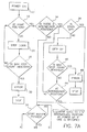
- the machine control logic polls the home or tray down position sensor 14 (see Figures 1 and 4) to see if it is blocked or unblocked.
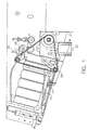
- the home position 14 sensor is an opto interrupter type and is blocked when a tab on the paper support tray 16 moves into a position known as the home or tray down position 18. If the paper support tray 16 is determined to be down as indicated by the home position sensor 14 then the operation sequence continues, if not, then the machine logic will issue a set amount of stepper down steps 20 to the stepper motor 22 (see Figure 1). The stepper motor 22 then drives the paper support tray 16 downward through lift chain 24, and cable anchor point 26. A side view showing these drive train elements is found in Figure 1.
- the stepper motor 22 will continue to drive downward until the sensor 14 becomes blocked or a Max Step Count 28 is reached.
- the Max Step Count represents a number of steps that should be able to have driven the paper support tray 16 it's full travel plus a small amount of extra steps. If the "Max Step Count" 28 is reached without blocking the sensor 14 then an error 30 is flagged and reported back to the operator through the operator control panel found in Figure 2. If the Home Position Sensor 14 is blocked, the process continues.
- This intermediate position 34 is set by the customer through a PC attached to the scanner and an appropriate PC to scanner communications (typically SCSI).
- the Graphical User Interface or GUI would contain a display that would allow the customer to choose an intermediate position that is best suited for the size of batches that the customer wants to feed.
- This intermediate position 34 can be set with granularity as fine as one stepper motor 22 step. For example, in the implementation described here, each stepper motor 22 steps equates to approximately 3 or 4 sheets of 20 lb.
- the machine logic assumes that the maximum capacity or 1,000 sheets is desired. This 1,000 sheet tray position is equivalent to the paper support tray 16 being all the way down and at the position where the "Home Position" sensor 14 is blocked. At this point in the process, the machine logic checks to see if the stack up sensor 36 is indicating that the feed module 38 has been raised up which in turn unblocks the opto interrupter "Stack Up Sensor" 36. This is accomplished when the stack of documents 40 comes into contact with the drive tires located within the feed module. See Figure 5. A solid plastic flag 42 which is part of the feed module housing rotates with the housing until such a point where the flag 42 no longer block the opto interrupter sensor.
- stepper motor command is bounded by a "Max Step Count" 46 and if this count is reached, the machine logic will flag an error 48.
- the customer can command the scanner to feed documents by pressing a start scan button 50 on the scanner. (It is also possible to give this command through the host PC and it's SCSI communications interface.)
- the machine logic receives the start command and polls the "Paper Present Sensor” 52 to determine is paper has been loaded into the paper support tray 16 to be fed.
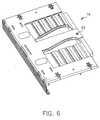
- the "Paper Present Sensor” 52 see Figures 2 and 6, is a reflective type sensor located within the paper support tray 16. If there is no paper present 54, then no scanning will commence. If paper is present 54, then the machine logic will check to see if the "Stack Up Sensor" 36 is indicating that the document stack 40 is at the "Stack Up” position 56 or not.
- the "Stack Up" position 56 where the paper is at the desired elevation for reliable feeding 58. If the stack up sensor 36 is satisfied then feeding 58 commences. If the stack up sensor 36 is not satisfied then the tray is driven up until it become unblocked and the paper has reached the desired height for reliable feeding and feeding commences. Feeding of the sheets involves engaging an electromechanical clutch that causes the feed module 38 tires to rotate and thereby advance the top sheet into the paper path 60. This electromechanical clutch is in turn coupled to the scanner's main drive motor and drive system from which it receives it's power. Once a sheet is fed from the paper support tray 16, it is advanced through the scanner via a series of rollers and belts.
- an illumination source and a CCD - Lens Reduction image forming system produces the desired electronic image.
- the sheet continues through the paper transport and is delivered to an output tray. See Figure 3 which depicts a side view of a typical image forming paper path.
Landscapes
- Engineering & Computer Science (AREA)
- Mechanical Engineering (AREA)
- Sheets, Magazines, And Separation Thereof (AREA)
- Controlling Sheets Or Webs (AREA)
Abstract
Description
Claims (8)
- A capacity control system for a paper supply elevator comprising:a paper support;a paper sensor for detecting presence of paper on said paper support;a home position sensor for detecting a home position of said paper support;a stack up sensor for detecting a topmost sheet of paper in a stack of papers located on said paper support;an intermittent drive for raising and lowering said paper support;a control panel for inputting an expected paper stack size; anda control circuit for said intermittent drive which causes said intermittent drive to move said paper support to a position corresponding to said expected paper stack size.
- A capacity control system as in claim 1 wherein said control circuit causes said intermittent drive to return said paper support to said position corresponding to said expected paper stack size after said stack of paper has been fed to a processing device.
- A capacity control system as in claim 1 wherein said intermittent drive is a stepper motor.
- A capacity control system as in claim 1 wherein said intermittent drive is a servo control motor.
- A capacity control system as in claim 1 wherein said paper supply elevator is mounted on a scanner.
- A capacity control system as in claim 4 wherein said control panel is mounted on said scanner.
- A capacity control system as in claim 4 wherein said control panel is a computer electronically connected to said scanner.
- A capacity control system as in claim 1 wherein said paper sensor is mounted on said paper support.
Applications Claiming Priority (2)
| Application Number | Priority Date | Filing Date | Title |
|---|---|---|---|
| US909334 | 2001-07-19 | ||
| US09/909,334 US20030015836A1 (en) | 2001-07-19 | 2001-07-19 | Capacity control system for a paper supply elevator |
Publications (2)
| Publication Number | Publication Date |
|---|---|
| EP1281645A2 true EP1281645A2 (en) | 2003-02-05 |
| EP1281645A3 EP1281645A3 (en) | 2004-01-28 |
Family
ID=25427050
Family Applications (1)
| Application Number | Title | Priority Date | Filing Date |
|---|---|---|---|
| EP02077808A Withdrawn EP1281645A3 (en) | 2001-07-19 | 2002-07-12 | A capacity control system for a paper supply elevator |
Country Status (3)
| Country | Link |
|---|---|
| US (1) | US20030015836A1 (en) |
| EP (1) | EP1281645A3 (en) |
| JP (1) | JP2003054769A (en) |
Cited By (1)
| Publication number | Priority date | Publication date | Assignee | Title |
|---|---|---|---|---|
| EP2274216A4 (en) * | 2008-05-05 | 2013-12-25 | Eastman Kodak Co | Variable feeder tray capacity control |
Families Citing this family (10)
| Publication number | Priority date | Publication date | Assignee | Title |
|---|---|---|---|---|
| US20070096387A1 (en) * | 2002-09-26 | 2007-05-03 | Sciurba Thomas K | Method for controlling stack-advancing in a reproduction apparatus |
| EP1403200A3 (en) * | 2002-09-26 | 2005-04-06 | Eastman Kodak Company | Method for controlling stack-advancing in a reproduction apparatus |
| JP4033844B2 (en) * | 2004-03-15 | 2008-01-16 | 富士通株式会社 | Paper sheet feeding device |
| JP4178167B2 (en) * | 2006-07-10 | 2008-11-12 | シャープ株式会社 | Image forming apparatus |
| JP4772633B2 (en) * | 2006-09-28 | 2011-09-14 | 京セラミタ株式会社 | Paper feeder |
| JP4979515B2 (en) * | 2007-08-28 | 2012-07-18 | キヤノン株式会社 | Sheet feeding apparatus and image forming apparatus |
| US7887045B2 (en) * | 2008-07-18 | 2011-02-15 | Lexmark International, Inc. | Method for dynamically lifting elevator platform of media input tray during ongoing media process |
| JP2013230877A (en) * | 2012-04-27 | 2013-11-14 | Riso Kagaku Corp | Sheet feeding apparatus |
| US8820739B1 (en) * | 2013-04-04 | 2014-09-02 | Xerox Corporation | Method for optimizing feeder module feeder tray capacity |
| JP7032872B2 (en) * | 2017-06-01 | 2022-03-09 | キヤノン株式会社 | Image formation system |
Family Cites Families (2)
| Publication number | Priority date | Publication date | Assignee | Title |
|---|---|---|---|---|
| US4052051A (en) * | 1975-07-10 | 1977-10-04 | Pitney-Bowes, Inc. | Sheet feeder |
| JPH0432424A (en) * | 1990-05-25 | 1992-02-04 | Hitachi Koki Co Ltd | Paper feeder |
-
2001
- 2001-07-19 US US09/909,334 patent/US20030015836A1/en not_active Abandoned
-
2002
- 2002-07-12 EP EP02077808A patent/EP1281645A3/en not_active Withdrawn
- 2002-07-18 JP JP2002209812A patent/JP2003054769A/en active Pending
Cited By (1)
| Publication number | Priority date | Publication date | Assignee | Title |
|---|---|---|---|---|
| EP2274216A4 (en) * | 2008-05-05 | 2013-12-25 | Eastman Kodak Co | Variable feeder tray capacity control |
Also Published As
| Publication number | Publication date |
|---|---|
| EP1281645A3 (en) | 2004-01-28 |
| US20030015836A1 (en) | 2003-01-23 |
| JP2003054769A (en) | 2003-02-26 |
Similar Documents
| Publication | Publication Date | Title |
|---|---|---|
| EP1281645A2 (en) | A capacity control system for a paper supply elevator | |
| KR101311608B1 (en) | Sheet feeding apparatus and image reading apparatus | |
| EP2548079A1 (en) | A document camera based multifunction scanner-copier-printer-fax with an automatic paper feeder | |
| CN105197633B (en) | Sheet feeding-device, possess its original document feeder and image processing system | |
| CN1321046C (en) | Paper feeding device, image reading device and image forming device | |
| US8398069B2 (en) | Paper feeder with first and second paper loaders | |
| US11546482B2 (en) | Document reading apparatus, control method thereof, and storage medium | |
| JP2010143694A (en) | Document feeding apparatus | |
| JP2005303610A (en) | Automatic manuscript feeder and image reader | |
| WO2023276806A1 (en) | Document conveying device | |
| US11459197B2 (en) | Document feeder | |
| JP6676298B2 (en) | Image reading device and image forming device | |
| JP4943226B2 (en) | Automatic document feeder | |
| US11652942B2 (en) | Image processing apparatus, method for controlling the same, and storage medium | |
| US12103797B2 (en) | Reading apparatus, control method for reading apparatus, and storage medium | |
| US11505417B2 (en) | Document feeder | |
| JP6369422B2 (en) | Paper feeding device and image forming apparatus | |
| JP7807913B2 (en) | Document reader | |
| JP2017024847A (en) | Image reading apparatus and image forming apparatus | |
| JP3747986B2 (en) | Document feeder | |
| JP2014150357A (en) | Image reading device | |
| JP2020061627A (en) | Image reading device, image reading method | |
| JP2007320670A (en) | Document feeder and image reading device | |
| JP2008228210A (en) | Image reader and image scanner | |
| JP6869035B2 (en) | Image reader |
Legal Events
| Date | Code | Title | Description |
|---|---|---|---|
| PUAI | Public reference made under article 153(3) epc to a published international application that has entered the european phase |
Free format text: ORIGINAL CODE: 0009012 |
|
| AK | Designated contracting states |
Designated state(s): AT BE BG CH CY CZ DE DK EE ES FI FR GB GR IE IT LI LU MC NL PT SE SK TR |
|
| AX | Request for extension of the european patent |
Extension state: AL LT LV MK RO SI |
|
| PUAL | Search report despatched |
Free format text: ORIGINAL CODE: 0009013 |
|
| AK | Designated contracting states |
Kind code of ref document: A3 Designated state(s): AT BE BG CH CY CZ DE DK EE ES FI FR GB GR IE IT LI LU MC NL PT SE SK TR |
|
| AX | Request for extension of the european patent |
Extension state: AL LT LV MK RO SI |
|
| RIC1 | Information provided on ipc code assigned before grant |
Ipc: 7B 65H 1/18 A |
|
| 17P | Request for examination filed |
Effective date: 20040630 |
|
| AKX | Designation fees paid |
Designated state(s): DE FR GB |
|
| 17Q | First examination report despatched |
Effective date: 20050307 |
|
| STAA | Information on the status of an ep patent application or granted ep patent |
Free format text: STATUS: THE APPLICATION IS DEEMED TO BE WITHDRAWN |
|
| 18D | Application deemed to be withdrawn |
Effective date: 20050719 |