EP1281520A1 - Ink jet printing apparatus and method of controlling temperature of head of ink jet printing apparatus - Google Patents
Ink jet printing apparatus and method of controlling temperature of head of ink jet printing apparatus Download PDFInfo
- Publication number
- EP1281520A1 EP1281520A1 EP02016891A EP02016891A EP1281520A1 EP 1281520 A1 EP1281520 A1 EP 1281520A1 EP 02016891 A EP02016891 A EP 02016891A EP 02016891 A EP02016891 A EP 02016891A EP 1281520 A1 EP1281520 A1 EP 1281520A1
- Authority
- EP
- European Patent Office
- Prior art keywords
- heating
- temperature
- printhead
- heating mode
- ink jet
- Prior art date
- Legal status (The legal status is an assumption and is not a legal conclusion. Google has not performed a legal analysis and makes no representation as to the accuracy of the status listed.)
- Granted
Links
- 238000007641 inkjet printing Methods 0.000 title claims abstract description 26
- 238000000034 method Methods 0.000 title claims description 30
- 238000010438 heat treatment Methods 0.000 claims abstract description 219
- 238000007639 printing Methods 0.000 claims abstract description 77
- 101100208381 Caenorhabditis elegans tth-1 gene Proteins 0.000 description 14
- 230000007613 environmental effect Effects 0.000 description 12
- 230000007423 decrease Effects 0.000 description 10
- 230000001276 controlling effect Effects 0.000 description 8
- 230000008569 process Effects 0.000 description 8
- 230000000694 effects Effects 0.000 description 7
- 230000002411 adverse Effects 0.000 description 4
- 238000010586 diagram Methods 0.000 description 4
- 239000003086 colorant Substances 0.000 description 3
- 230000006870 function Effects 0.000 description 3
- 230000001133 acceleration Effects 0.000 description 2
- 238000007796 conventional method Methods 0.000 description 2
- 238000012986 modification Methods 0.000 description 2
- 230000004048 modification Effects 0.000 description 2
- 230000000704 physical effect Effects 0.000 description 2
- 230000006399 behavior Effects 0.000 description 1
- 238000009924 canning Methods 0.000 description 1
- 238000012937 correction Methods 0.000 description 1
- 238000003780 insertion Methods 0.000 description 1
- 230000037431 insertion Effects 0.000 description 1
- 230000014759 maintenance of location Effects 0.000 description 1
- 230000007246 mechanism Effects 0.000 description 1
- 230000015654 memory Effects 0.000 description 1
- 238000011084 recovery Methods 0.000 description 1
- 230000001105 regulatory effect Effects 0.000 description 1
- 239000000758 substrate Substances 0.000 description 1
- 238000012546 transfer Methods 0.000 description 1
- 230000003936 working memory Effects 0.000 description 1
Images


Classifications
-
- B—PERFORMING OPERATIONS; TRANSPORTING
- B41—PRINTING; LINING MACHINES; TYPEWRITERS; STAMPS
- B41J—TYPEWRITERS; SELECTIVE PRINTING MECHANISMS, i.e. MECHANISMS PRINTING OTHERWISE THAN FROM A FORME; CORRECTION OF TYPOGRAPHICAL ERRORS
- B41J2/00—Typewriters or selective printing mechanisms characterised by the printing or marking process for which they are designed
- B41J2/005—Typewriters or selective printing mechanisms characterised by the printing or marking process for which they are designed characterised by bringing liquid or particles selectively into contact with a printing material
- B41J2/01—Ink jet
- B41J2/015—Ink jet characterised by the jet generation process
- B41J2/04—Ink jet characterised by the jet generation process generating single droplets or particles on demand
- B41J2/045—Ink jet characterised by the jet generation process generating single droplets or particles on demand by pressure, e.g. electromechanical transducers
- B41J2/04501—Control methods or devices therefor, e.g. driver circuits, control circuits
- B41J2/04528—Control methods or devices therefor, e.g. driver circuits, control circuits aiming at warming up the head
-
- B—PERFORMING OPERATIONS; TRANSPORTING
- B41—PRINTING; LINING MACHINES; TYPEWRITERS; STAMPS
- B41J—TYPEWRITERS; SELECTIVE PRINTING MECHANISMS, i.e. MECHANISMS PRINTING OTHERWISE THAN FROM A FORME; CORRECTION OF TYPOGRAPHICAL ERRORS
- B41J2/00—Typewriters or selective printing mechanisms characterised by the printing or marking process for which they are designed
- B41J2/005—Typewriters or selective printing mechanisms characterised by the printing or marking process for which they are designed characterised by bringing liquid or particles selectively into contact with a printing material
- B41J2/01—Ink jet
- B41J2/015—Ink jet characterised by the jet generation process
- B41J2/04—Ink jet characterised by the jet generation process generating single droplets or particles on demand
- B41J2/045—Ink jet characterised by the jet generation process generating single droplets or particles on demand by pressure, e.g. electromechanical transducers
- B41J2/04501—Control methods or devices therefor, e.g. driver circuits, control circuits
- B41J2/04553—Control methods or devices therefor, e.g. driver circuits, control circuits detecting ambient temperature
-
- B—PERFORMING OPERATIONS; TRANSPORTING
- B41—PRINTING; LINING MACHINES; TYPEWRITERS; STAMPS
- B41J—TYPEWRITERS; SELECTIVE PRINTING MECHANISMS, i.e. MECHANISMS PRINTING OTHERWISE THAN FROM A FORME; CORRECTION OF TYPOGRAPHICAL ERRORS
- B41J2/00—Typewriters or selective printing mechanisms characterised by the printing or marking process for which they are designed
- B41J2/005—Typewriters or selective printing mechanisms characterised by the printing or marking process for which they are designed characterised by bringing liquid or particles selectively into contact with a printing material
- B41J2/01—Ink jet
- B41J2/015—Ink jet characterised by the jet generation process
- B41J2/04—Ink jet characterised by the jet generation process generating single droplets or particles on demand
- B41J2/045—Ink jet characterised by the jet generation process generating single droplets or particles on demand by pressure, e.g. electromechanical transducers
- B41J2/04501—Control methods or devices therefor, e.g. driver circuits, control circuits
- B41J2/04563—Control methods or devices therefor, e.g. driver circuits, control circuits detecting head temperature; Ink temperature
-
- B—PERFORMING OPERATIONS; TRANSPORTING
- B41—PRINTING; LINING MACHINES; TYPEWRITERS; STAMPS
- B41J—TYPEWRITERS; SELECTIVE PRINTING MECHANISMS, i.e. MECHANISMS PRINTING OTHERWISE THAN FROM A FORME; CORRECTION OF TYPOGRAPHICAL ERRORS
- B41J2/00—Typewriters or selective printing mechanisms characterised by the printing or marking process for which they are designed
- B41J2/005—Typewriters or selective printing mechanisms characterised by the printing or marking process for which they are designed characterised by bringing liquid or particles selectively into contact with a printing material
- B41J2/01—Ink jet
- B41J2/015—Ink jet characterised by the jet generation process
- B41J2/04—Ink jet characterised by the jet generation process generating single droplets or particles on demand
- B41J2/045—Ink jet characterised by the jet generation process generating single droplets or particles on demand by pressure, e.g. electromechanical transducers
- B41J2/04501—Control methods or devices therefor, e.g. driver circuits, control circuits
- B41J2/0458—Control methods or devices therefor, e.g. driver circuits, control circuits controlling heads based on heating elements forming bubbles
Definitions
- the present invention relates to an ink jet printing apparatus that carries out printing using thermal energy and a method of controlling the temperature of a head of the ink jet printing apparatus, and in particular, to improvements in control of the head temperature in a low-temperature environment.
- an ink jet printing apparatus or the like is subjected to various adverse effects of a variation in environmental temperature or in temperature of a head composed of integrated printing elements. This is because the temperature varies physical property values such as the viscosity or surface tension of ink. Further, with what is called a bubble jet (registered trade name) printing method of using thermal energy to generate bubbles in ink in order to eject the ink, a variation in temperature may vary the conditions under which bubbles are generated.
- the amount of ink droplets ejected from a printhead or the accuracy of landing on may vary, resulting in a variation in density, a nonuniform density, or a variation in tone.
- a conventional method of controlling the temperature of the printhead is described in USP 5861895, Japanese Patent Application Laid-Open No. 5-220964 (1993).
- This control method employs a configuration that uses a heater for heating the printhead (a heater exclusively used to control temperature or used both for ink ejection and for temperature control) and a temperature sensor detecting temperature related to the printhead to feed back the temperature detected by the temperature sensor so as to adjust the amount of heat generated by the heater.
- Another conventional method does not use such feedback control but provides open loop control such that the heater is regulated to achieve an arbitrary preset temperature.
- Such methods of controlling the heater of the printhead are roughly classified into four types: methods of always adjusting the head temperature (using feedback control based on a detected temperature), methods of adjusting the head temperature at fixed time intervals (using feedback control based on a detected temperature), methods of adjusting the head temperature when it exceeds an environmental temperature (using feedback control based on a detected temperature), and methods of modulating the pulse width of a heat pulse.
- a known one detects the head temperature at the start of printing or during every printing operation for one line, and compares the detected temperature with a reference temperature to provide such control that the printhead is heated until a target temperature is reached if the detected temperature is lower than the reference temperature.
- a fixed upper limit is generally set for the heating time in order to limit a decrease in throughput associated with the heating operation to below the fixed value.
- the head temperature may be controlled in real time by comparing the head temperature with the reference temperature and adding a non-printing pulse to the head on the bases of a difference between the head temperature and the reference temperature.
- USP 6260940 Application discloses a technique of preheating the printhead during sheet feeding or during an acceleration or deceleration period of the printhead.
- USP 5861895 discloses a technique of varying the waveform of a drive signal on the basis of the head temperature to suppress a variation in amount of ink ejected from the printhead, the variation attributed to the head temperature, while reducing a self temperature increase.
- Japanese Patent Application Laid-open No. 5-220965 (1993) discloses a technique of using ejecting heating means (heater) to heat the printhead up to a first temperature and using subheating means having a subheater to heat the printhead up to a second temperature higher than the first temperature.
- USP 5417246 discloses a technique of heating, if a plurality of transporting means are provided, the printhead using timing corresponding to a transporting operation of each transporting means.
- USP 5417246 discloses a technique of providing such control that the temperature is maintained depending on the type of printing in order to vary the amount of ink ejected from the head depending on whether the type of an object is a character or an image.
- the above control is disadvantageous in that throughput decreases substantially owing to the heating time set for the head.
- a text or the like using black with which the temperature of the printhead does not increase significantly (self-increase in temperature) during a printing operation, is printed using a multipath printing process, the throughput decreases further markedly when the printhead is heated for every print line.
- an upper limit is set for the heating time.
- printing is executed with the printhead insufficiently heated.
- this tendency appears clearly in a portion of the image printed immediately after the start of printing, when a self temperature increase is small.
- problems such as a nonuniform density are prone to occur. Accordingly, this method is improper for high-grade image printing.
- a printing pulse and a heating pulse must be individually controlled, thereby requiring the apparatus to be complicated.
- the heating operation period is limited to the period in which no printing operation is performed, i.e. a sheet feeding period or a carriage acceleration or deceleration period, then insufficient heating may be provided during the heating operation period as with the case in which the upper limit on the heating time is set to a smaller value as described previously.
- motors for the transporting system and carriage are accelerated or decelerated to increase power consumption.
- the capacity of a power supply must be increased.
- heat retention be executed depending on the type of printing by controlling heat retention when a noticeable high-grade image, which may create a problem as described above, is printed.
- advanced determining means is required which can automatically determine the image to be printed.
- the temperature of ink may vary with the environmental temperature even with the same head temperature.
- the behavior of ejection may vary.
- temperature detecting means is provided which measures the environmental temperature in addition to the head temperature.
- this increases costs and requires correction of a difference between the ink temperature and the environmental temperature caused by heat generated by the printing apparatus itself. Therefore, the required control is complicated.
- the present invention provides an ink jet printing apparatus that carries out printing by ejecting ink to a printing medium through nozzles formed in a printhead, the apparatus being characterized by comprising heating means for heating the printhead, temperature detecting means for detecting the temperature of the printhead, comparing means for comparing the temperature of the printhead with a predetermined first heating threshold temperature, heating mode setting means for setting, before a printing operation, a heating mode in which the printhead can be heated if the temperature of the printhead detected by the temperature detecting means is lower than the first heating threshold temperature, and control means for controlling the heating means on the basis of a result of the comparison executed by the comparing means and depending on whether or not the heating mode has been set, the control means using the heating means to heat the printhead when the heating mode has been set and when the detected temperature of the printhead is lower than the second heating threshold temperature.
- the present invention provides a method of controlling temperature of a head of an ink jet printing apparatus that carries out printing by ejecting ink to a printing medium through nozzles formed in the printhead, the method being characterized by comprising a heating step of heating the printhead, a temperature detecting step of detecting the temperature of the printhead, a comparing step of comparing the temperature of the printhead with a predetermined first heating threshold temperature, a heating mode setting step of setting, before a printing operation, a heating mode in which the printhead can be heated if the temperature of the printhead detected by the temperature detecting means is lower than the heating threshold temperature, and a control step of controlling the heating means on the basis of a result of the comparison executed by the comparing means and depending on whether or not the heating mode has been set, the control step executing the heating step to heat the printhead when the heating mode has been set and when the detected temperature of the printhead is lower than the second heating threshold temperature.
- the head temperature T is compared with the head first heating threshold temperature (Tth1). If the result of the comparison is T ⁇ Tth1, then it is determined that the heating mode is to be set. Then, the heating mode setting means sets the heating mode. With the heating mode set, for example, at the start of each printing operation for one line, the temperature T obtained by the detecting means is compared with the heating second threshold temperature (Tth2). Then, if the value T is smaller than the value Tth2, the printhead is heated up to a heating target temperature 2 (Tend2). Further, the heating mode is set to be cleared, for example, five minutes after the setting of the heating mode. Then, even after the head temperature has increased in a low-temperature environment, a heating process can be executed until the entire ink is sufficiently warmed.
- Tth1 head first heating threshold temperature
- An ink jet printing apparatus 50 shown in Fig. 1, employs a serial scan method and has a carriage 53 supported along guide shafts 51 and 52 so as to reciprocate along a main-scanning direction, shown by arrow A.
- the carriage 53 is reciprocated in the main-scanning direction by a carriage motor and a driving force transmitting mechanism such as a belt which transmits driving force.
- the carriage 53 has a printhead 10 (not shown in Fig. 1) mounted thereon and an ink tank 54 also mounted thereon to supply ink to the print head 10.
- the printhead 10 and the ink tank 54 may constitute an ink jet cartridge.
- a printing medium P is inserted through an insertion port formed in a front surface of the apparatus and is then transported by a feed roller 56 in a sub-scanning direction, shown by arrow B.
- the ink jet printing apparatus 50 sequentially prints the printing medium by repeating a printing operation of ejecting ink to a printing area of the printing medium on a platen 57 and a transporting operation of transporting the printing medium P in a sub-scanning direction orthogonal to the main-scanning direction.
- a recovery system unit 58 is provided at an end (the left end in Fig. 1) of an area in which the carriage 53 is moved, so as to lie opposite that surface of a printhead 101 mounted on the carriage 53 in which nozzles 15 are formed.
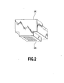
- Figs. 2 to 4A and 4B show the configuration of the printhead used in the ink jet printing apparatus according to this embodiment.
- Fig. 2 is a perspective view of the printhead.
- Fig. 3 is a bottom view thereof.
- Fig. 4A is a sectional view taken along like IV-IV in Fig. 3.
- Fig. 4B is a partially enlarged view of Fig. 4A.
- a printhead 101 has ejecting sections 132 for a plurality of colors (for example, four colors including yellow, cyan, magenta, and black).
- Each ejecting section 132 has two nozzle lines having a density of 300 dpi and arranged in parallel at an interval of 600 dpi. This enables each color to be printed at substantially 600 dpi.
- reference numeral 133 denotes a heater provided in each nozzle of the printhead 101 as an electrothermal converting element.
- the heater 133 functions as ejection energy generating means for converting electric energy into thermal energy, which causes bubbles to be generated in ink, so that energy generated by the bubbles can be used to eject the ink.
- the heater 133 functions as heating means for heating the printhead by providing electric energy insufficient to eject the ink.
- the heater 133 also functions as a self temperature increasing means.
- the printhead 101 is provided with a head temperature sensor (temperature detecting means) 121 near the nozzle lines 122 in each ejecting section 123.
- the head temperature sensor 121 detects the temperature (head temperature) of each ejecting section 123 of the printhead 101.
- Fig. 5 is a block diagram schematically showing the configuration of a control system according to this embodiment.
- reference numeral 200 denotes a CPU that performs operations such as predetermined calculations, counting, comparisons, determinations, and control.
- Reference numeral 201 denotes a ROM stores control programs and the like to be executed by the CPU 200.
- Reference numeral 202 denotes a RAM functioning as a data memory in which data and the like sent out by a host computer are stored and as a working memory that allows the CPU to execute calculating processes.
- the ROM and the RAM are connected to the CPU 200.
- the CPU 200, the ROM 201, and the RAM 202 constitute comparing means for performing a comparing operation, described later, heating mode setting means, and control means.
- the CPU 200 connects to a heater driver 133 that drives the heaters 133 provided in the printhead 101, a motor driver 133A for a carriage motor 203 acting as a driving source for the carriage 53, a motor driver 204A for a PF motor acting as a driving source for transportation of the printing medium, a head temperature sensor 121 that detects the temperature in the printhead 101, and others.
- the CPU 200 executes ejection control by supplying the heater driver 133A with driving data (image data) and a driving control signal (a heat pulse signal) for the ejection heater to cause ink droplets to be ejected from the printhead 101.
- the CPU 200 executes head temperature control to adjust the temperature of the printhead 101.
- the CPU 200 controls the carriage motor 203 via the motor driver 203A to drive the carriage 53 in the main-scanning direction.
- Tth 20°C
- step S5 if the head temperature is lower than the reference temperature, the printhead is heated for 10 ms (step S5). Then, a count N in a heating number counter is incremented by one (step S6). Then, it is determined whether or not the count in the heating number counter exceeds an upper limit, for example, 40 (step S7). If the count exceeds the upper limit, the printhead is not further heated but a printing operation is performed (step S8). If the heating number is equal to or smaller than 40, the process returns to step S3 to obtain the temperature. Then, the above operation is repeated for every line or every plural lines until the printing operation is completed (step S9).
- the heating number is counted in order to set an upper limit on the heating time for low temperatures to limit a decrease in throughput to below the specified value. Further, if much time is required for heating, a user may determine that there is a failure in the main body. Thus, the heating number counting is also effective in preventing this incorrect determination.
- Fig. 7 shows a variation in head temperature which may occur after a printing operation has been started by the control operation shown in Fig. 6.
- a heating operation is performed for a specified time. Then, if the head temperature does not reach the heating threshold temperature after the specified time has passed, the heating operation is stopped and one line is printed. If this printing operation for one line involves a large amount of print data, the temperature increases (self temperature increase) as a result of the heating during the printing operation as shown in the figure. In particular, when an image of nature is printed, a large number of colors are used and dots are densely printed compared to printing of text data in black (Bk text printing). Consequently, the self temperature increase is larger. In a section ending when a reference temperature is reached (a heating section (A) in Fig. 7), the printhead is heated before each printing operation for one line as shown in Fig. 8. In a section for the heating threshold temperature Tth (a non-heating section (B) in Fig. 7), heating is omitted as shown in Fig. 9.
- the increase in temperature caused by the printing of the first page may cause the head temperature to exceed the heating threshold value.
- the heating threshold temperature may be set to be equal to or lower than the normal temperature (for example, 20°C) in order to avoid a decrease in throughput caused by heating, and the head temperature may increase to about 25°C at the start of printing of the next page.
- the temperature of ink ejected remains at 25°C or lower.
- the amount of ink ejected may decrease or the density may become nonuniform.
- the head temperature is detected, a difference between the normal-temperature environment and the low-temperature environment is not detected. Further, even in the low-temperature environment, heat is transmitted from the head to the ink over time. Consequently, the difference in printing between the normal-temperature environment and the low-temperature environment decreases gradually.
- the temperature detecting means must be located away from heated locations in the printing apparatus in order to eliminate the effects of heating associated with driving of the printing apparatus. Furthermore, if the temperature detecting means is installed on the same substrate, the environmental temperature must be estimated so that the estimated value is corrected in view of the effects of heating. This increases costs and requires complicated control.
- a first embodiment of the present invention provides the following control:
- the detected head temperature T is compared with the heating threshold temperature Tth1 to determine whether or not the environment is in a low-temperature state and heating is thus required. If it is determined that T ⁇ Tth1 and that heating is required, then a heating mode is set in which a heating flag is turned on to enable a heating operation. Then, the detected temperature T, obtained at the start of each printing operation for one line, is compared with a heating threshold temperature Tth2. If the detected temperature T is lower than the heating threshold temperature Tth2, the printhead is heated up to a heating target temperature Tend2 set to be higher than the heating threshold temperature Tth2.
- the heating flag is turned on and five minutes later, turned off to set the heating mode. This enables a heating process to be executed until the temperature of the entire ink increases after the head temperature has increased in the low-temperature environment.
- the entire print head 101 can be heated. Accordingly, the temperature of ink channels in the printhead 101 can be increased. Therefore, the ink stored in the tank and having low temperature can be easily warmed during transfer to the ejection nozzles.
- the heating flag is provided to set and clear the heating mode. Consequently, the heating flag can be turned on for a specified time regardless of the head temperature so as to execute a heating process during this period. Accordingly, the head can be sufficiently heated using only the head temperature detecting means and without the needs for a plurality of temperature detecting means for detecting the environmental temperature or the ink temperature, correcting or estimating means, and the like.
- Fig. 10 shows a variation in head temperature and a variation in temperature of ink in the channels according to the first embodiment.
- a specified time for example, five minutes
- a printing operation for one page is started (step S17).
- Tth2 for example, 30°C
- step S19 determines whether T ⁇ Tth2 or the upper limit of the heating time is reached. If it is determined at step S19 that T ⁇ Tth2, then during steps S19 to S24, the printhead is heated until the head temperature reaches the heating target temperature Tend2 or the upper limit of the heating time is reached. Then, at step S25, one line is printed.
- a heating operation is performed on every page printed within a specified time after the start.
- the heating operation is continuously performed if the head temperature remains at the threshold value Tth1 at the start of the next printing operation performed after a specified time has passed.
- Tth1 the threshold value
- the first embodiment does not comprise means for detecting the environmental temperature or ink temperature or means for correcting or estimating a detected temperature, but can sufficiently heat the printhead using only the head temperature detecting means. That is, the printhead can be heated so that even if the head temperature is equivalent to or higher than the normal temperature, adverse effects on images such as a nonuniform density and unwanted stripes are not produced in a low-temperature environment during the first specified time. Further, after the temperature of the entire printhead has increased or if the environment is at the normal temperature, heating of the head is omitted to avoid a decrease in throughput.
- checking whether or not a heating operation is to be performed is carried out before the start of each printing operation for one line. However, it may be carried out every specified time or immediately after each printing operation for one line (before the start of the next printing operation).
- the second embodiment also has the configuration shown in Figs. 1 to 5.
- Fig. 12A and 12B shows this heating sequence.
- a heating operation is repeated until the head temperature reaches the heating target temperature or the number of repetitions reaches a specified value.
- step S45 the head temperature T is compared with the heating target temperature (in this case, Tend1). If the head temperature is equal to or higher than the heating target temperature, the heating sequence is ended. On the other hand, if the head temperature is lower than the heating target temperature, the process shifts to step S46. At step S46, it is determined whether or not the value N of the heating number counter has reached the predetermined number of repetitions. Then, the operations in steps S43 to S46 are repeated until the predetermined number of repetitions is reached.
- the heating target temperature in this case, Tend1
- a printing operation for one page is started at step S26, shown in Fig. 12. That is, before the start of each printing operation for one line, the heating mode flag H is checked to determine whether or not the heating mode has been entered. If the heating mode has not been entered, one line is printed at step S29. If the heating mode has been entered, the target temperature Tend2, the heating time Theat1, and the number of repetitions L1 are set and the heating sequence described previously and shown in Fig. 13 is executed (step S28). Subsequently, at step S29, one line is printed to determine whether or not one page has been completely printed (step S30).
- the heating target temperature is set to be higher than the heating threshold temperature.
- the heating target temperature may be set to equal the heating threshold temperature.
- a heating operation is preformed at the top of the page.
- the page is ensured to be printed at the desirable head temperature from its top.
- a heating operation is performed for every line, thereby reducing a variation in time interval between printing scans.
- the printing operation performed during page feeding is effective in minimizing a decrease in throughput.
- the heating flag may be turned off on the basis of the number of sheets printed after the heating flag has been turned on or a preset upper limit value for the predetermined head temperature.
- the heating means for the printhead is composed of the heaters for ink ejection provided in the respective nozzles in each ejecting section of the printhead.
- heaters different from those for ink ejection may be used.
- the upper limit of the ink heating temperature in the heating mode must be such that ink is not ejected through the nozzles at this temperature.
- the heating means may be provided not only in the nozzles but also outside them.
- the heating mode in which the printhead can be heated, is set before a printing operation. Further, when the heating mode is set and the detected temperature of the printhead is lower than the heating second threshold temperature, the heating means heats the printhead. Consequently, even in a low-temperature environment, the heating operation keeps ink good and suitable for printing. Further, ink is stably ejected to enable a proper image to be printed. Moreover, at the normal temperature, the heating operation is unwanted and thus omitted, thereby achieving efficient ink temperature retention control. Furthermore, this embodiment does not require a plurality of detecting means for detecting the environmental temperature or head temperature or require a detected temperature to be corrected. Therefore, this embodiment can be inexpensively and simply constructed.
Abstract
Description
Claims (6)
- An ink jet printing apparatus that carries out printing by ejecting ink to a printing medium through nozzles formed in a printhead, the apparatus characterized by comprising:heating means for heating said printhead;temperature detecting means for detecting the temperature of said printhead;comparing means for comparing the temperature of said printhead with a predetermined first heating threshold temperature;heating mode setting means for setting, before a printing operation, a heating mode in which said printhead can be heated if the temperature of the printhead is lower than said first heating threshold temperature; andcontrol means for controlling said heating means on the basis of a result of the comparison executed by said comparing means and depending on whether or not the heating mode has been set,said control means using said heating means to heat the printhead when said heating mode has been set and when the detected temperature of the printhead is lower than a second heating threshold temperature that is higher than first heating threshold.
- An ink jet printing apparatus according to claim 1, characterized in that said heating mode setting means clears setting of the heating mode a specified time after the heating mode has been set.
- An ink jet printing apparatus according to claim 1, characterized in that said heating mode setting means clears setting of the heating mode in response to capping of the printhead.
- An ink jet printing apparatus according to claim 1, characterized in that said heating mode setting means clears setting of the heating mode on the basis of the number of sheets printed after setting of the heating mode.
- An ink jet printing apparatus according to claim 1, characterized in that said heating mode setting means clears setting of the heating mode when the temperature of the printhead reaches a predetermined temperature.
- A method of controlling temperature of a head of an ink jet printing apparatus that carries out printing by ejecting ink to a printing medium through nozzles formed in the printhead, the method characterized by comprising:a heating step of heating said printhead;a temperature detecting step of detecting the temperature of said printhead;a comparing step of comparing the temperature of said printhead with a predetermined first heating threshold temperature;a heating mode setting step of setting, before a printing operation, a heating mode in which said printhead can be heated if the temperature of the printhead is lower than a second heating threshold temperature that is higer than first heating threshold; anda control step of controlling said heating means on the basis of a result of the comparison executed by said comparing means and depending on whether or not the heating mode has been set,the control step executing said heating step to heat the printhead when said heating mode has been set and when the detected temperature of the printhead is lower than said heating threshold temperature.
Applications Claiming Priority (2)
| Application Number | Priority Date | Filing Date | Title |
|---|---|---|---|
| JP2001232916 | 2001-07-31 | ||
| JP2001232916A JP5037762B2 (en) | 2001-07-31 | 2001-07-31 | Ink jet recording apparatus and head temperature control method in ink jet recording apparatus |
Publications (2)
| Publication Number | Publication Date |
|---|---|
| EP1281520A1 true EP1281520A1 (en) | 2003-02-05 |
| EP1281520B1 EP1281520B1 (en) | 2007-04-04 |
Family
ID=19064760
Family Applications (1)
| Application Number | Title | Priority Date | Filing Date |
|---|---|---|---|
| EP02016891A Expired - Lifetime EP1281520B1 (en) | 2001-07-31 | 2002-07-30 | Ink jet printing apparatus and method of controlling temperature of head of ink jet printing apparatus |
Country Status (4)
| Country | Link |
|---|---|
| US (1) | US6957880B2 (en) |
| EP (1) | EP1281520B1 (en) |
| JP (1) | JP5037762B2 (en) |
| DE (1) | DE60219245T2 (en) |
Families Citing this family (13)
| Publication number | Priority date | Publication date | Assignee | Title |
|---|---|---|---|---|
| JP2004230816A (en) * | 2003-01-31 | 2004-08-19 | Canon Inc | Temperature detection method |
| JP2007290355A (en) * | 2006-03-31 | 2007-11-08 | Canon Inc | Inkjet recording apparatus, and method for controlling inkjet recording head temperature |
| JP2010214866A (en) * | 2009-03-18 | 2010-09-30 | Canon Inc | Recorder and recording control method |
| JP2011194823A (en) * | 2010-03-23 | 2011-10-06 | Seiko Epson Corp | Method for printing by inkjet recording method |
| JP6004897B2 (en) | 2012-01-10 | 2016-10-12 | キヤノン株式会社 | Recording apparatus and recording method |
| JP6203025B2 (en) | 2013-12-10 | 2017-09-27 | キヤノン株式会社 | Recording apparatus and recording data processing method |
| US10166763B2 (en) | 2014-06-18 | 2019-01-01 | Canon Kabushiki Kaisha | Printing apparatus, printing method and storage medium |
| JP6360410B2 (en) | 2014-10-07 | 2018-07-18 | キヤノン株式会社 | Recording apparatus and driving method thereof |
| JP2016074152A (en) | 2014-10-07 | 2016-05-12 | キヤノン株式会社 | Recording device and driving method for the same |
| JP7094812B2 (en) | 2018-07-17 | 2022-07-04 | キヤノン株式会社 | Recording device, recording method, and program |
| JP2020037209A (en) | 2018-09-03 | 2020-03-12 | キヤノン株式会社 | Ink jet recorder, ink jet recording method, and program |
| JP7451257B2 (en) | 2020-03-26 | 2024-03-18 | キヤノン株式会社 | Inkjet recording device and inkjet recording method |
| JP2022050012A (en) | 2020-09-17 | 2022-03-30 | キヤノン株式会社 | Recording device, control method, and conveyance device |
Citations (9)
| Publication number | Priority date | Publication date | Assignee | Title |
|---|---|---|---|---|
| JPS63268667A (en) * | 1987-04-28 | 1988-11-07 | Toshiba Corp | Thermal recorder |
| JPH0245166A (en) * | 1988-08-05 | 1990-02-15 | Nec Home Electron Ltd | Density gradation control type thermal printer |
| US5168284A (en) | 1991-05-01 | 1992-12-01 | Hewlett-Packard Company | Printhead temperature controller that uses nonprinting pulses |
| JPH05220965A (en) | 1992-02-07 | 1993-08-31 | Canon Inc | Ink jet recorder |
| JPH05220964A (en) | 1992-02-07 | 1993-08-31 | Canon Inc | Delivery control method in ink jet recording head |
| US5417246A (en) | 1989-10-27 | 1995-05-23 | American Cyanamid Company | Pneumatic controls for ophthalmic surgical system |
| US5861895A (en) | 1991-01-09 | 1999-01-19 | Canon Kabushiki Kaisha | Ink jet recording method and apparatus controlling driving signals in accordance with head temperature |
| JP2001008009A (en) * | 1999-06-23 | 2001-01-12 | Sharp Corp | Facsimile equipment |
| US6260940B1 (en) | 1998-05-04 | 2001-07-17 | Canon Kabushiki Kaisha | Ink jet printing system having ink preheating during non-printing periods |
Family Cites Families (11)
| Publication number | Priority date | Publication date | Assignee | Title |
|---|---|---|---|---|
| JPS61146553A (en) * | 1984-12-21 | 1986-07-04 | Canon Inc | Liquid jet recording device |
| ATE235376T1 (en) * | 1991-07-30 | 2003-04-15 | Canon Kk | APPARATUS AND METHOD FOR INKJET RECORDING |
| JP2872461B2 (en) | 1991-10-04 | 1999-03-17 | キヤノン株式会社 | Ink jet recording device |
| JPH05338176A (en) * | 1992-06-11 | 1993-12-21 | Canon Inc | Ink jet recording apparatus |
| JPH0671875A (en) * | 1992-06-30 | 1994-03-15 | Fuji Xerox Co Ltd | Ink-jet recorder |
| US5475405A (en) * | 1993-12-14 | 1995-12-12 | Hewlett-Packard Company | Control circuit for regulating temperature in an ink-jet print head |
| JPH07323552A (en) * | 1994-05-31 | 1995-12-12 | Canon Inc | Ink droplet discharge quantity controlling method, ink jet recorder and information processing system |
| EP1486334B1 (en) * | 1994-12-29 | 2009-08-26 | Canon Kabushiki Kaisha | Ink-jet apparatus employing ink-jet head having a plurality of ink ejection heaters, corresponding to each ink ejection opening |
| JPH1199666A (en) * | 1997-09-30 | 1999-04-13 | Minolta Co Ltd | Ink jet recorder |
| JP3809280B2 (en) * | 1998-09-01 | 2006-08-16 | キヤノン株式会社 | Recording method and apparatus |
| JP2003039641A (en) * | 2001-07-31 | 2003-02-13 | Canon Inc | Ink jet recorder and ink jet recording method |
-
2001
- 2001-07-31 JP JP2001232916A patent/JP5037762B2/en not_active Expired - Fee Related
-
2002
- 2002-07-29 US US10/206,105 patent/US6957880B2/en not_active Expired - Fee Related
- 2002-07-30 DE DE60219245T patent/DE60219245T2/en not_active Expired - Lifetime
- 2002-07-30 EP EP02016891A patent/EP1281520B1/en not_active Expired - Lifetime
Patent Citations (9)
| Publication number | Priority date | Publication date | Assignee | Title |
|---|---|---|---|---|
| JPS63268667A (en) * | 1987-04-28 | 1988-11-07 | Toshiba Corp | Thermal recorder |
| JPH0245166A (en) * | 1988-08-05 | 1990-02-15 | Nec Home Electron Ltd | Density gradation control type thermal printer |
| US5417246A (en) | 1989-10-27 | 1995-05-23 | American Cyanamid Company | Pneumatic controls for ophthalmic surgical system |
| US5861895A (en) | 1991-01-09 | 1999-01-19 | Canon Kabushiki Kaisha | Ink jet recording method and apparatus controlling driving signals in accordance with head temperature |
| US5168284A (en) | 1991-05-01 | 1992-12-01 | Hewlett-Packard Company | Printhead temperature controller that uses nonprinting pulses |
| JPH05220965A (en) | 1992-02-07 | 1993-08-31 | Canon Inc | Ink jet recorder |
| JPH05220964A (en) | 1992-02-07 | 1993-08-31 | Canon Inc | Delivery control method in ink jet recording head |
| US6260940B1 (en) | 1998-05-04 | 2001-07-17 | Canon Kabushiki Kaisha | Ink jet printing system having ink preheating during non-printing periods |
| JP2001008009A (en) * | 1999-06-23 | 2001-01-12 | Sharp Corp | Facsimile equipment |
Non-Patent Citations (4)
| Title |
|---|
| PATENT ABSTRACTS OF JAPAN vol. 013, no. 067 (M - 798) 15 February 1989 (1989-02-15) * |
| PATENT ABSTRACTS OF JAPAN vol. 014, no. 206 (M - 0967) 26 April 1990 (1990-04-26) * |
| PATENT ABSTRACTS OF JAPAN vol. 017, no. 664 (M - 1523) 8 December 1993 (1993-12-08) * |
| PATENT ABSTRACTS OF JAPAN vol. 2000, no. 16 8 May 2001 (2001-05-08) * |
Also Published As
| Publication number | Publication date |
|---|---|
| EP1281520B1 (en) | 2007-04-04 |
| DE60219245T2 (en) | 2008-01-03 |
| JP2003039642A (en) | 2003-02-13 |
| DE60219245D1 (en) | 2007-05-16 |
| US6957880B2 (en) | 2005-10-25 |
| JP5037762B2 (en) | 2012-10-03 |
| US20030025748A1 (en) | 2003-02-06 |
Similar Documents
| Publication | Publication Date | Title |
|---|---|---|
| EP1486334B1 (en) | Ink-jet apparatus employing ink-jet head having a plurality of ink ejection heaters, corresponding to each ink ejection opening | |
| KR100463359B1 (en) | Ink jet print apparatus, ink jet printing method, program, and computer-readable storage medium that stores the program | |
| US7296877B2 (en) | Ink jet printing apparatus and print position setting method | |
| EP0867298B1 (en) | Printing apparatus and check pattern printing method | |
| EP1281520B1 (en) | Ink jet printing apparatus and method of controlling temperature of head of ink jet printing apparatus | |
| US20060125850A1 (en) | Method of compensating missing nozzle and printer using the same | |
| US6997541B2 (en) | Print position adjusting method and ink jet printing apparatus and ink jet printing system using print position adjusting method | |
| EP0995607A2 (en) | Printing apparatus and method for correcting print positions | |
| US6880909B2 (en) | Method and apparatus for adjusting drop velocity | |
| US8348372B2 (en) | Ink jet printing apparatus and ink jet printing method | |
| JP6333200B2 (en) | Inkjet recording apparatus, inkjet recording method, and recording head | |
| US7798593B2 (en) | Ink jet printing apparatus and method for controlling temperature of the same | |
| US9981468B2 (en) | Ink jet printing apparatus and method for controlling inkjet printing apparatus | |
| US20020057308A1 (en) | Printing apparatus and printing method | |
| JP2002225238A (en) | Ink jet printing apparatus and its printing position adjustment method | |
| US20080297552A1 (en) | Ink jet printing apparatus and ink jet printing method | |
| US20070024652A1 (en) | Method and apparatus for printing | |
| US8465116B2 (en) | Printing apparatus and printing method | |
| JP6584144B2 (en) | Inkjet printing device | |
| EP0650836B1 (en) | Temperature control of thermal ink-jet print heads by using synchronous non-nucleating pulses | |
| JP4497825B2 (en) | Inkjet recording method and inkjet recording apparatus | |
| JPH10109409A (en) | Ink jet recording apparatus and control method thereof | |
| JP2003039641A (en) | Ink jet recorder and ink jet recording method | |
| JP2006224381A (en) | Inkjet recording device | |
| JP2006168095A (en) | Inkjet recording method |
Legal Events
| Date | Code | Title | Description |
|---|---|---|---|
| PUAI | Public reference made under article 153(3) epc to a published international application that has entered the european phase |
Free format text: ORIGINAL CODE: 0009012 |
|
| AK | Designated contracting states |
Designated state(s): AT BE BG CH CY CZ DE DK EE ES FI FR GB GR IE IT LI LU MC NL PT SE SK TR |
|
| AX | Request for extension of the european patent |
Extension state: AL LT LV MK RO SI |
|
| 17P | Request for examination filed |
Effective date: 20030625 |
|
| AKX | Designation fees paid |
Designated state(s): DE FR GB IT |
|
| 17Q | First examination report despatched |
Effective date: 20040212 |
|
| GRAP | Despatch of communication of intention to grant a patent |
Free format text: ORIGINAL CODE: EPIDOSNIGR1 |
|
| GRAS | Grant fee paid |
Free format text: ORIGINAL CODE: EPIDOSNIGR3 |
|
| GRAA | (expected) grant |
Free format text: ORIGINAL CODE: 0009210 |
|
| AK | Designated contracting states |
Kind code of ref document: B1 Designated state(s): DE FR GB IT |
|
| REG | Reference to a national code |
Ref country code: GB Ref legal event code: FG4D |
|
| REF | Corresponds to: |
Ref document number: 60219245 Country of ref document: DE Date of ref document: 20070516 Kind code of ref document: P |
|
| ET | Fr: translation filed | ||
| PLBE | No opposition filed within time limit |
Free format text: ORIGINAL CODE: 0009261 |
|
| STAA | Information on the status of an ep patent application or granted ep patent |
Free format text: STATUS: NO OPPOSITION FILED WITHIN TIME LIMIT |
|
| 26N | No opposition filed |
Effective date: 20080107 |
|
| PGFP | Annual fee paid to national office [announced via postgrant information from national office to epo] |
Ref country code: FR Payment date: 20090722 Year of fee payment: 8 |
|
| PGFP | Annual fee paid to national office [announced via postgrant information from national office to epo] |
Ref country code: IT Payment date: 20090717 Year of fee payment: 8 |
|
| REG | Reference to a national code |
Ref country code: FR Ref legal event code: ST Effective date: 20110331 |
|
| PG25 | Lapsed in a contracting state [announced via postgrant information from national office to epo] |
Ref country code: IT Free format text: LAPSE BECAUSE OF NON-PAYMENT OF DUE FEES Effective date: 20100730 Ref country code: FR Free format text: LAPSE BECAUSE OF NON-PAYMENT OF DUE FEES Effective date: 20100802 |
|
| PGFP | Annual fee paid to national office [announced via postgrant information from national office to epo] |
Ref country code: GB Payment date: 20150727 Year of fee payment: 14 Ref country code: DE Payment date: 20150731 Year of fee payment: 14 |
|
| REG | Reference to a national code |
Ref country code: DE Ref legal event code: R119 Ref document number: 60219245 Country of ref document: DE |
|
| GBPC | Gb: european patent ceased through non-payment of renewal fee |
Effective date: 20160730 |
|
| PG25 | Lapsed in a contracting state [announced via postgrant information from national office to epo] |
Ref country code: DE Free format text: LAPSE BECAUSE OF NON-PAYMENT OF DUE FEES Effective date: 20170201 |
|
| PG25 | Lapsed in a contracting state [announced via postgrant information from national office to epo] |
Ref country code: GB Free format text: LAPSE BECAUSE OF NON-PAYMENT OF DUE FEES Effective date: 20160730 |