EP1281382A2 - Method of controlling massaging machine - Google Patents
Method of controlling massaging machine Download PDFInfo
- Publication number
- EP1281382A2 EP1281382A2 EP02016513A EP02016513A EP1281382A2 EP 1281382 A2 EP1281382 A2 EP 1281382A2 EP 02016513 A EP02016513 A EP 02016513A EP 02016513 A EP02016513 A EP 02016513A EP 1281382 A2 EP1281382 A2 EP 1281382A2
- Authority
- EP
- European Patent Office
- Prior art keywords
- motor
- massaging
- voltage
- patient
- patting
- Prior art date
- Legal status (The legal status is an assumption and is not a legal conclusion. Google has not performed a legal analysis and makes no representation as to the accuracy of the status listed.)
- Withdrawn
Links
Images




Classifications
-
- A—HUMAN NECESSITIES
- A61—MEDICAL OR VETERINARY SCIENCE; HYGIENE
- A61H—PHYSICAL THERAPY APPARATUS, e.g. DEVICES FOR LOCATING OR STIMULATING REFLEX POINTS IN THE BODY; ARTIFICIAL RESPIRATION; MASSAGE; BATHING DEVICES FOR SPECIAL THERAPEUTIC OR HYGIENIC PURPOSES OR SPECIFIC PARTS OF THE BODY
- A61H1/00—Apparatus for passive exercising; Vibrating apparatus; Chiropractic devices, e.g. body impacting devices, external devices for briefly extending or aligning unbroken bones
-
- A—HUMAN NECESSITIES
- A61—MEDICAL OR VETERINARY SCIENCE; HYGIENE
- A61H—PHYSICAL THERAPY APPARATUS, e.g. DEVICES FOR LOCATING OR STIMULATING REFLEX POINTS IN THE BODY; ARTIFICIAL RESPIRATION; MASSAGE; BATHING DEVICES FOR SPECIAL THERAPEUTIC OR HYGIENIC PURPOSES OR SPECIFIC PARTS OF THE BODY
- A61H15/00—Massage by means of rollers, balls, e.g. inflatable, chains, or roller chains
- A61H15/0078—Massage by means of rollers, balls, e.g. inflatable, chains, or roller chains power-driven
-
- A—HUMAN NECESSITIES
- A61—MEDICAL OR VETERINARY SCIENCE; HYGIENE
- A61H—PHYSICAL THERAPY APPARATUS, e.g. DEVICES FOR LOCATING OR STIMULATING REFLEX POINTS IN THE BODY; ARTIFICIAL RESPIRATION; MASSAGE; BATHING DEVICES FOR SPECIAL THERAPEUTIC OR HYGIENIC PURPOSES OR SPECIFIC PARTS OF THE BODY
- A61H15/00—Massage by means of rollers, balls, e.g. inflatable, chains, or roller chains
-
- A—HUMAN NECESSITIES
- A61—MEDICAL OR VETERINARY SCIENCE; HYGIENE
- A61H—PHYSICAL THERAPY APPARATUS, e.g. DEVICES FOR LOCATING OR STIMULATING REFLEX POINTS IN THE BODY; ARTIFICIAL RESPIRATION; MASSAGE; BATHING DEVICES FOR SPECIAL THERAPEUTIC OR HYGIENIC PURPOSES OR SPECIFIC PARTS OF THE BODY
- A61H23/00—Percussion or vibration massage, e.g. using supersonic vibration; Suction-vibration massage; Massage with moving diaphragms
- A61H23/02—Percussion or vibration massage, e.g. using supersonic vibration; Suction-vibration massage; Massage with moving diaphragms with electric or magnetic drive
-
- A—HUMAN NECESSITIES
- A61—MEDICAL OR VETERINARY SCIENCE; HYGIENE
- A61H—PHYSICAL THERAPY APPARATUS, e.g. DEVICES FOR LOCATING OR STIMULATING REFLEX POINTS IN THE BODY; ARTIFICIAL RESPIRATION; MASSAGE; BATHING DEVICES FOR SPECIAL THERAPEUTIC OR HYGIENIC PURPOSES OR SPECIFIC PARTS OF THE BODY
- A61H7/00—Devices for suction-kneading massage; Devices for massaging the skin by rubbing or brushing not otherwise provided for
-
- A—HUMAN NECESSITIES
- A61—MEDICAL OR VETERINARY SCIENCE; HYGIENE
- A61H—PHYSICAL THERAPY APPARATUS, e.g. DEVICES FOR LOCATING OR STIMULATING REFLEX POINTS IN THE BODY; ARTIFICIAL RESPIRATION; MASSAGE; BATHING DEVICES FOR SPECIAL THERAPEUTIC OR HYGIENIC PURPOSES OR SPECIFIC PARTS OF THE BODY
- A61H7/00—Devices for suction-kneading massage; Devices for massaging the skin by rubbing or brushing not otherwise provided for
- A61H7/007—Kneading
-
- A—HUMAN NECESSITIES
- A61—MEDICAL OR VETERINARY SCIENCE; HYGIENE
- A61H—PHYSICAL THERAPY APPARATUS, e.g. DEVICES FOR LOCATING OR STIMULATING REFLEX POINTS IN THE BODY; ARTIFICIAL RESPIRATION; MASSAGE; BATHING DEVICES FOR SPECIAL THERAPEUTIC OR HYGIENIC PURPOSES OR SPECIFIC PARTS OF THE BODY
- A61H15/00—Massage by means of rollers, balls, e.g. inflatable, chains, or roller chains
- A61H2015/0007—Massage by means of rollers, balls, e.g. inflatable, chains, or roller chains with balls or rollers rotating about their own axis
- A61H2015/0028—Massage by means of rollers, balls, e.g. inflatable, chains, or roller chains with balls or rollers rotating about their own axis disc-like, i.e. diameter substantially greater than width
-
- A—HUMAN NECESSITIES
- A61—MEDICAL OR VETERINARY SCIENCE; HYGIENE
- A61H—PHYSICAL THERAPY APPARATUS, e.g. DEVICES FOR LOCATING OR STIMULATING REFLEX POINTS IN THE BODY; ARTIFICIAL RESPIRATION; MASSAGE; BATHING DEVICES FOR SPECIAL THERAPEUTIC OR HYGIENIC PURPOSES OR SPECIFIC PARTS OF THE BODY
- A61H2201/00—Characteristics of apparatus not provided for in the preceding codes
- A61H2201/01—Constructive details
- A61H2201/0119—Support for the device
- A61H2201/0138—Support for the device incorporated in furniture
-
- A—HUMAN NECESSITIES
- A61—MEDICAL OR VETERINARY SCIENCE; HYGIENE
- A61H—PHYSICAL THERAPY APPARATUS, e.g. DEVICES FOR LOCATING OR STIMULATING REFLEX POINTS IN THE BODY; ARTIFICIAL RESPIRATION; MASSAGE; BATHING DEVICES FOR SPECIAL THERAPEUTIC OR HYGIENIC PURPOSES OR SPECIFIC PARTS OF THE BODY
- A61H2201/00—Characteristics of apparatus not provided for in the preceding codes
- A61H2201/01—Constructive details
- A61H2201/0119—Support for the device
- A61H2201/0138—Support for the device incorporated in furniture
- A61H2201/0149—Seat or chair
-
- A—HUMAN NECESSITIES
- A61—MEDICAL OR VETERINARY SCIENCE; HYGIENE
- A61H—PHYSICAL THERAPY APPARATUS, e.g. DEVICES FOR LOCATING OR STIMULATING REFLEX POINTS IN THE BODY; ARTIFICIAL RESPIRATION; MASSAGE; BATHING DEVICES FOR SPECIAL THERAPEUTIC OR HYGIENIC PURPOSES OR SPECIFIC PARTS OF THE BODY
- A61H2201/00—Characteristics of apparatus not provided for in the preceding codes
- A61H2201/14—Special force transmission means, i.e. between the driving means and the interface with the user
- A61H2201/1427—Wobbling plate
-
- A—HUMAN NECESSITIES
- A61—MEDICAL OR VETERINARY SCIENCE; HYGIENE
- A61H—PHYSICAL THERAPY APPARATUS, e.g. DEVICES FOR LOCATING OR STIMULATING REFLEX POINTS IN THE BODY; ARTIFICIAL RESPIRATION; MASSAGE; BATHING DEVICES FOR SPECIAL THERAPEUTIC OR HYGIENIC PURPOSES OR SPECIFIC PARTS OF THE BODY
- A61H2201/00—Characteristics of apparatus not provided for in the preceding codes
- A61H2201/16—Physical interface with patient
- A61H2201/1602—Physical interface with patient kind of interface, e.g. head rest, knee support or lumbar support
- A61H2201/1623—Back
-
- A—HUMAN NECESSITIES
- A61—MEDICAL OR VETERINARY SCIENCE; HYGIENE
- A61H—PHYSICAL THERAPY APPARATUS, e.g. DEVICES FOR LOCATING OR STIMULATING REFLEX POINTS IN THE BODY; ARTIFICIAL RESPIRATION; MASSAGE; BATHING DEVICES FOR SPECIAL THERAPEUTIC OR HYGIENIC PURPOSES OR SPECIFIC PARTS OF THE BODY
- A61H2201/00—Characteristics of apparatus not provided for in the preceding codes
- A61H2201/16—Physical interface with patient
- A61H2201/1602—Physical interface with patient kind of interface, e.g. head rest, knee support or lumbar support
- A61H2201/1654—Layer between the skin and massage elements, e.g. fluid or ball
-
- A—HUMAN NECESSITIES
- A61—MEDICAL OR VETERINARY SCIENCE; HYGIENE
- A61H—PHYSICAL THERAPY APPARATUS, e.g. DEVICES FOR LOCATING OR STIMULATING REFLEX POINTS IN THE BODY; ARTIFICIAL RESPIRATION; MASSAGE; BATHING DEVICES FOR SPECIAL THERAPEUTIC OR HYGIENIC PURPOSES OR SPECIFIC PARTS OF THE BODY
- A61H2201/00—Characteristics of apparatus not provided for in the preceding codes
- A61H2201/16—Physical interface with patient
- A61H2201/1657—Movement of interface, i.e. force application means
- A61H2201/1664—Movement of interface, i.e. force application means linear
- A61H2201/1669—Movement of interface, i.e. force application means linear moving along the body in a reciprocating manner
-
- A—HUMAN NECESSITIES
- A61—MEDICAL OR VETERINARY SCIENCE; HYGIENE
- A61H—PHYSICAL THERAPY APPARATUS, e.g. DEVICES FOR LOCATING OR STIMULATING REFLEX POINTS IN THE BODY; ARTIFICIAL RESPIRATION; MASSAGE; BATHING DEVICES FOR SPECIAL THERAPEUTIC OR HYGIENIC PURPOSES OR SPECIFIC PARTS OF THE BODY
- A61H2201/00—Characteristics of apparatus not provided for in the preceding codes
- A61H2201/50—Control means thereof
- A61H2201/5005—Control means thereof for controlling frequency distribution, modulation or interference of a driving signal
-
- A—HUMAN NECESSITIES
- A61—MEDICAL OR VETERINARY SCIENCE; HYGIENE
- A61H—PHYSICAL THERAPY APPARATUS, e.g. DEVICES FOR LOCATING OR STIMULATING REFLEX POINTS IN THE BODY; ARTIFICIAL RESPIRATION; MASSAGE; BATHING DEVICES FOR SPECIAL THERAPEUTIC OR HYGIENIC PURPOSES OR SPECIFIC PARTS OF THE BODY
- A61H2201/00—Characteristics of apparatus not provided for in the preceding codes
- A61H2201/50—Control means thereof
- A61H2201/5007—Control means thereof computer controlled
-
- A—HUMAN NECESSITIES
- A61—MEDICAL OR VETERINARY SCIENCE; HYGIENE
- A61H—PHYSICAL THERAPY APPARATUS, e.g. DEVICES FOR LOCATING OR STIMULATING REFLEX POINTS IN THE BODY; ARTIFICIAL RESPIRATION; MASSAGE; BATHING DEVICES FOR SPECIAL THERAPEUTIC OR HYGIENIC PURPOSES OR SPECIFIC PARTS OF THE BODY
- A61H2205/00—Devices for specific parts of the body
- A61H2205/08—Trunk
- A61H2205/081—Back
-
- A—HUMAN NECESSITIES
- A61—MEDICAL OR VETERINARY SCIENCE; HYGIENE
- A61H—PHYSICAL THERAPY APPARATUS, e.g. DEVICES FOR LOCATING OR STIMULATING REFLEX POINTS IN THE BODY; ARTIFICIAL RESPIRATION; MASSAGE; BATHING DEVICES FOR SPECIAL THERAPEUTIC OR HYGIENIC PURPOSES OR SPECIFIC PARTS OF THE BODY
- A61H37/00—Accessories for massage
Definitions
- This invention relates to a method of controlling a massaging machine.
- Physical stimuli to a human body have been classified into the following six types: stroking, kneading, pushing, vibrating, pulling and patting. These stimuli are communicated to a body surface or hypodermic soft tissues to directly stimulate the peripheral nerves so as to relax the body tension. Indirectly, they accelerate the recovery of functions of the body as a whole, thereby improving the natural healing power of the body and the natural tendency to maintain the body in a natural condition. It has been expected that such massaging stimuli have therapeutic effects.
- the body contacting portion of a massaging operation is performed in different manners.
- the masseur may form a fist and pat the body on the side of the little finger.
- the strength of operation can be controlled by forming the fist tightly or lightly.
- the masseur may open the operating hand with all fingers stretched and pat the patient'sbody repeatedly on the side of the little finger so as to provide small vibrations to the body.
- the masseur may further clasp both hands and pat the patient's body with fingers separated so as to deliver elastic forces.
- Various methods of reproducing these effects mechanically have been tried and incorporated into a massaging machine in the form of a chair.
- One of conventional kinds of massaging machine was comprised of a structure dedicated to a patting operation, driven by a dedicated driving circuit.
- Another kind included contact members to carry out a repetitive patting action. If a structure dedicated to a patting action is used, the patient can enjoy the feeling of being massaged by a live masseur but the machine tends to become noisy. If it is combined with another kind of massaging machine, it becomes too expensive to be feasible.
- the method of using contact members is advantageous because they can be operated by adding a simple mechanism for tapping operation and a simple program but the patient does not necessarily receive the same feeling of being treated by a live masseur because the oscillatory stimuli are delivered too continuously.
- Massaging machines would be more highly valued if they were capable of delivering to the patient the feelingof being massaged by the fist or clasped hands of a masseur, but it has been a difficult proposal.
- the motor of which the rotary motion is transmitted to massaging members of a massaging machine is adapted to receive a driving signal which repeats switching on and off the motor such that the motor is operated intermittently.
- the massaging members are provided for kneading and stretching back muscles.
- the present invention makes effective use of such massaging members, their control mechanism and theircontrol circuit such that the patient will have a sensation close to that received from a live masseur.
- a pulsed voltage is inputted according to this invention such that the motor is switched on and off at specified intervals and is operated intermittently and that the massaging members can provide a more pleasant sensation to the patient.
- FIG. 1 is a diagonal external view of such a massaging machine 10 for schematically showing its structure (the cover sheet and the cushion on the back supporting part 100a being removed).
- Fig. 2 is its side view with the outer shape and inner structure of its back supporting part 100a being shown.
- the massaging machine 10 is basically a reclining chair 100 with the back supporting part 100a incorporating a therapy unit 110 including massaging members 201a-d.
- the massaging members 201a-d protrude forward from the therapy unit 110 to the front surface of the back supporting part 100a covered by a cover sheet.
- the massaging members include a first pair 201a and 201b on the righthand and left-hand sides of the back muscle and a second pair 201c and 201d similarly disposed below the first pair 201a and 201b.
- the therapy unit 110 is supported by a pair of cross-sectionally Ushaped guide rails (guiding means) 101R and 101L such that the openings of their Ushapes face each other and adapted to move upward and downward along the guide rails 101R and 101L by the rotary driving motion of pinions 310 which engage with racks inside the guide rails 101R and 101L.
- Fig. 3 is a front view of the therapy unit 110
- Fig. 4 is its right-hand side view
- Fig. 5 is its back view
- Fig. 6 is is diagonal frontal view
- Fig. 7 is its diagonal back view.
- the front surface of the therapy unit 110 is covered with a planar base board 111 with its upper end part bent backward and its middle part provided with an approximately rectangular opening 1111 through which the massaging members 201a-d protrude.
- the base board 111 also includes a removed portion 1112 and an opening 1113 so as to prevent possible interference with moving parts such as a gear.
- Fig. 8 is a front view of a treatment part 200 attached to the base board 1111
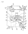
- Fig. 9 is its back view
- Fig. 10 is its diagonal back view taken from an upward position
- Fig. 11 is its frontal view taken from its right-hand side
- Fig. 12 is its diagonal frontal view taken from the left-hand side
- Fig. 13 is its diagonal back view taken from a lower position.
- the four massaging members 201ad are rotatably supported at the tips of approximately V-shaped arms 202R and 202L of which base parts are affixed to arm supporting members 203R and 203L.
- These arm-supporting members 203R and 203L are affixed respectively to a side surface of a bearing case 2031R or 2031L.
- These bearing cases 2031R and 2031L are rotatably engaged with sloped sleeves 207R and 207L through bearings which rotate along the peripheral surfaces of the sloped sleeves 207R and 207L.
- the sloped sleeves 207R and 207L are cylindrically shaped and are affixed to a kneading shaft 205 obliquely from both sides with respect to its axial direction so as to slope symmetrically in the leftright direction.
- the bearing cases 2031R and 2031L are provided not only with a base part 20311R and 20311L for engaging with the outer periphery of corresponding one of the sloped sleeves 207 but also with a link receiving part 20312R or 20312L to which is engaged a spherically formed end of a link 209R or 209L supported so as to swing along the spherical surface.
- a patting shaft 206 is disposed parallel to and above the kneading shaft 205.
- Cylindrical eccentric sleeves 208R and 208L made eccentric in radia direction are affixed to both sides of the patting shaft 206 at positions corresponding to the sloped sleeves 207.
- the two eccentric sleeves 208 are attached to the patting shaft 206 so as to be eccentric in opposite directions with respect to the patting shaft 206.
- Bearing cases 2081R and 2081L are rotatably engaged to the outer periphery of the eccentric sleeves 208R and 208L through bearings which rotate along the peripheral surface.
- the eccentric sleeves 208 have a base part 20811R and 20811L engaged to the outer periphery and a link receiving part 20812R or 20812L protruding in the peripheral direction.
- One end of a link 209(R or L) is connected to the bearing case 2031(R or L), and the other end of the link 209(R or L) is supported by the link receiving part 20812(R or L) so as to swing in the axial direction of the patting shaft 206.
- the kneading shaft 205 and the patting shaft 206 are rotatably supported from both sides through bearings by planar holder brackets 204R and 204L affixed to the baseboard 111.
- Figs. 14 and 15 are both a back view of the base board 111 with some components removed for the purpose of disclosure.
- the kneading shaft 205 is operated by a mobr 210 affixed to a planar supporting member 112 which is bent more or less into an M shape, covering the back side of the kneading shaft 205 and the patting shaft 206 and having one end affixed to the backside of the base member 111.
- the worm gear 214 engages with a worm wheel 215 which is coaxially affixed to the other circumference of the kneading shaft 205.
- the worm gear 214 and the worm wheel 215 are rotatably held inside a gear box 218 attached to the holder bracket 204R.
- the driving force of the motor 210 is communicated from the small pulley 211 to theendless belt 213 to the larger pulley 212 to the worm gear 214 to the worm wheel 215 while being decelerated, thereby causing the kneading shaft 205 to rotate.
- Figs. 16 and 17 are referenced next to explain the patting operation by the massaging machinestructured as explained above.
- the patting shaft 206 is driven by a motor 220 therefor affixed to the backside of the baseboard 111 through supporting members 113a and 113b as shown in Fig. 5.
- a small pulley 221 is attached to the drive shaft of the motor 220, and an endless belt 223 is stretched over this small pulley 221 and a large pulley 222 affixed coaxially to the patting shaft 206.
- the driving force of the motor 220 is communicated through the small pulley 221, the belt 223 and the patting shaft 206 while being decelerated.
- Mechanisms for moving the shaft upwards and downwards or forward and backward are not explained although they are provided.
- the rotation of the kneading shaft 205 is stopped while the patting shaft 206 is activated.
- the sloped sleeves 207 are positioned so as to be approximately perpendicular to the kneading shaft 205 of the arms 202R and 202L such that the massaging members are nearly perpendicular to the surface of the back ("zero point of kneading").
- a detector plate 216 detecting the zero point of kneading and a kneading position indicator 217 are coaxially affixed to the kneading shaft 205 (as shown in Fig. 14).
- the zero point detector plate 216 is a disk-shaped member having a slit at one position on its outer periphery such that the zero point of kneading can be detected by means of a photosensor placed behind the base board 111 at a corresponding position so as to sandwich the detector plate 216.
- the links 209 are supported rotatably through the eccentric sleeves 208 which rotate eccentrically with the rotation of the patting shaft 206, the distance between the axis of rotation of the patting shaft 206 and the link receiving parts 20312R and 20312L engaging the end parts of the patting shaft 206 changes as the patting shaft 206 is rotated. Since the arms 202R and 202L are supported rotatably around the kneading shaft 205, the arms 202R and 202L swing around the kneading shaft 205 to effect the desired patting operation as the motor 220 is operated to rotate the patting shaft 206 at an appropriate speed.
- Fig. 17 shows an actually measured pressure change with respect to time, the vertical axis representing the pressure felt by the patient's body. If a masseur pats a patient's body by hand, by contrast, the stimulus waveform is as shown in Fig. 19.
- Fig. 21 is a measured pressure change on the patient's body when a pulsed voltage of Fig. 20 was applied to the motor. It clearly shows that the resultant pressure change experienced by the patient is quite similar to that given by a masseur.
- Fig. 22 shows an example of driving circuit for providing such a voltage to the motor.
- any known pulse control method, pulse width modulation (PWM) method or phase control method may be used.
- numeral 11 indicates an input part comprising switches 11a, 11b and 11c for setting necessary conditions for generating a pulse with desired frequency and duty ratio.
- Numeral 12 indicates a calculating part which may comprise a microcomputer capable of generating and outputting required control signals from the input from the input part 11.
- a power control part 13 serves to receive the output from the calculating part 12 and to generate a power control signal for rotating the motor 220 for the patting operation.
- Fig. 22 shows an example wherein the power control part 13 is formed with two transistors 13a and 13b and a field effect transistor (FET) 13c.
- Numeral 14 indicates a power source for rectifying power from a commercial source 15 to supply power required by the motor 220.
- the switches of the input part 11 are operated first to set the frequency and the duty ratio (say, to 2.5Hz and 20%, respectively).
- the inputted data are transmitted to the calculating part 12 and the calculated result is transmitted to the power control part 13.
- the rectified voltage from the power source 14 is applied to the motor 220 but the transistors 13a and 13b and the FET 13c of the power control part 13 serve to switch on and off the source according to the output from the calculating part 12 to provide the pulsed voltage to the motor 220.
- pulse width modulation can also be effected by adjusting the input part 11 in this manner.
- Fig. 23 shows an example of a circuit for driving the motor for patting operation by the phase control method, indicating like parts by the same symbols as in Fig. 22.
- the input part 11 allows the user to select whether a phase control should be started at a zero-cross point of a waveform from a commercial power source 15 and stopped at a specified position or it should be started at a specified position and stopped at a zero-cross, as well as a phase angle corresponding to the pulse width.
- the calculating part 12 comprises a microcomputer capable of generating and outputting required control signals from the input from the input part 11.
- the power control part 13' serves to receive the output from the calculating part 12 and to generate a power control signal for rotating the motor 220 for the patting operation.
- the power control part 13' is formed with a triac 13a' and a diac 13b' which is connected to the gate terminal of this triac 13a' and insulated from a light emitting diode 13c' by a photocoupler.
- Numeral 14 again indicates a power source for rectifying power from a commercial source 15 to supply power required by the motor 220.
- the switches of the input part 11 are operated first to set the pulse rise position and phase angle with respect to the commercial power source 15 such as 50Hz for frequency of repetition and 20% as duty ratio.
- the inputted data are used by the calculating part 12 and the calculated result is outputted to the power control part 13'.
- Voltage from the power source 14 is being applied to the motor 220 but the triac 13a' and the diac 13b' of the power control part 13' serve to switch on and off the current according to the output from the calculating part 12 to apply to the motor 220 a pulsed voltage obtained by cutting off a portion of the sinusoidal waveform of the commercial power source 15.
- Fig. 24 shows an example of such method wherein another pulse signal B is superposed to a pulse signal A as shown above such that the width of pulse signal B is changed.
- a sinusoidal wave or a pulse signal B with higher frequency is generated and a logical product is taken with pulse signal A.
- the duty ratio of the sinusoidal wave or pulse signal B is changed and the outputted pulsed signal is used to drive the motor 220.
- This may be considered a kind of PWM method and if the duty ratio of pulse signal B is varied, the effective voltage value applied to the motor changes according to this ratio and a same effect is obtained as if the voltage has been varied or that the strengh of the patting operation is varied.
- the waveform of the pulse to be applied to the motor 220 may be generated by the microcomputer.
- the strength of patting may be varied also by changing the voltage of the pulse applied to the motor 220 and thereby changing the rotation of the motor.
- a pulse is modulated by another pulse so as to vary its effective voltage to be applied to the motor 220 such that the strength of patting is varied.
- the method of present invention makes it possible to use the mechanism of a conventional massage machine and to give the patient a pleasant sensation of massaging like that by a live masseur, not achieved by prior art massage machines.
Landscapes
- Health & Medical Sciences (AREA)
- Animal Behavior & Ethology (AREA)
- Pain & Pain Management (AREA)
- Physical Education & Sports Medicine (AREA)
- Rehabilitation Therapy (AREA)
- Life Sciences & Earth Sciences (AREA)
- Epidemiology (AREA)
- General Health & Medical Sciences (AREA)
- Public Health (AREA)
- Veterinary Medicine (AREA)
- Dermatology (AREA)
- Percussion Or Vibration Massage (AREA)
- Massaging Devices (AREA)
Abstract
Description
| Percentage of patients who felt it hurt | Percentage of patients who felt it was pleasant | |
| Conventional method | 91% | 9% |
| Method of this | 0% | 100% |
| Time | |
| Time during which the motor is switched on | 0.02-1 sec |
| Time during which the motor is switched off | 0.1-1 sec |
Claims (5)
- A method of controlling a massaging machine having massaging members and a motor for causing said massaging members to vibrate to massage a patient, said method comprising the step of applying to said motor a driving signal for repetitively switching on and off said motor for specified time lengths whereby said motor is intermittently activated.
- The method of claim 1 wherein one or more variables ofthe group consisting of pulse frequency, duty ratio, pulse number, pulse width and pulse interval are changed to vary the frequency by which said massaging members pat the patient.
- The method of claim 1 wherein an electrical voltage is applied to said motor as said driving signal and wherein said method includes the step of varying said voltage.
- The method of claim 2 wherein an electrical voltage is applied to said motor as said driving signal and wherein said method includes the step of varyingsaid voltage.
- The method of claim 1 wherein the strength with which said massaging members pat the patient is varied by carrying out pulse width modulation on the voltage applied to said motor as said driving signal to thereby vary the pulse width ofsaid voltage.
Applications Claiming Priority (2)
| Application Number | Priority Date | Filing Date | Title |
|---|---|---|---|
| JP2001232683 | 2001-07-31 | ||
| JP2001232683A JP3714208B2 (en) | 2001-07-31 | 2001-07-31 | Control method of massage machine |
Publications (2)
| Publication Number | Publication Date |
|---|---|
| EP1281382A2 true EP1281382A2 (en) | 2003-02-05 |
| EP1281382A3 EP1281382A3 (en) | 2003-07-09 |
Family
ID=19064567
Family Applications (1)
| Application Number | Title | Priority Date | Filing Date |
|---|---|---|---|
| EP02016513A Withdrawn EP1281382A3 (en) | 2001-07-31 | 2002-07-23 | Method of controlling massaging machine |
Country Status (5)
| Country | Link |
|---|---|
| US (1) | US6932779B2 (en) |
| EP (1) | EP1281382A3 (en) |
| JP (1) | JP3714208B2 (en) |
| KR (1) | KR20030011655A (en) |
| CN (1) | CN1226026C (en) |
Cited By (4)
| Publication number | Priority date | Publication date | Assignee | Title |
|---|---|---|---|---|
| CN100518706C (en) * | 2003-03-26 | 2009-07-29 | 松下电工株式会社 | Massage machine |
| CN100577132C (en) * | 2003-05-26 | 2010-01-06 | 发美利株式会社 | Chair type massage machine, cover for massage machine, cover for leg rest, and massage machine |
| CN108837200A (en) * | 2018-05-02 | 2018-11-20 | 王仁浒 | Multifunctional medical treatment chair |
| CN112274410A (en) * | 2020-09-15 | 2021-01-29 | 湖南明康中锦医疗科技发展有限公司 | Slapping mechanism of expectoration undershirt |
Families Citing this family (30)
| Publication number | Priority date | Publication date | Assignee | Title |
|---|---|---|---|---|
| JP2005137492A (en) * | 2003-11-05 | 2005-06-02 | Omron Healthcare Co Ltd | Massaging element projection quantity adjusting mechanism and massage machine |
| US20070106185A1 (en) * | 2004-04-30 | 2007-05-10 | Roman Ferber | Portable body massager |
| US7128721B2 (en) * | 2004-04-30 | 2006-10-31 | Homedics, Inc. | Portable body massager |
| US7470242B2 (en) | 2005-03-18 | 2008-12-30 | Fka Distributing Co. | Portable body massager having width adjustable massage members on translating carriage |
| TW200701974A (en) * | 2005-06-20 | 2007-01-16 | Family Co Ltd | Chair type massaging machine, massaging machine, operation device of chair type massaging machine, remote controller for chair type massaging machine |
| ES2288787B1 (en) * | 2005-08-26 | 2008-12-01 | Eurokeyton, S.A. | MASSAGE DEVICE. |
| US7419475B2 (en) | 2005-09-09 | 2008-09-02 | Fka Distibuting Co. | Body massager with illumination effects |
| USD536897S1 (en) * | 2005-09-16 | 2007-02-20 | Akasei Gmbh | Massage chair |
| JP2007089716A (en) * | 2005-09-27 | 2007-04-12 | Matsushita Electric Works Ltd | Massaging apparatus |
| US7597669B2 (en) | 2006-03-01 | 2009-10-06 | Fka Distributing Co. | Body massage apparatus |
| US8512265B2 (en) * | 2009-11-19 | 2013-08-20 | Fka Distributing Co. | Percussive massager |
| US10413473B2 (en) | 2012-03-14 | 2019-09-17 | Ralph Zipper | Sexual stimulation device using light therapy, vibration and physiological feedback |
| WO2013138658A1 (en) * | 2012-03-14 | 2013-09-19 | Zipper Ralph | Improved sexual stimulation device using light therapy and vibration |
| US10130550B2 (en) * | 2012-03-14 | 2018-11-20 | Ralph Zipper | Sexual stimulation device using light therapy, vibration and physiological feedback |
| CN202776940U (en) * | 2012-08-13 | 2013-03-13 | 林丹鹏 | Massage device with massage dynamic perception driving mechanism |
| US20140148743A1 (en) * | 2012-11-26 | 2014-05-29 | Jue-Yao Chen | Massage Fitness Apparatus for Waist, Abdomen, and Back |
| JP6688739B2 (en) * | 2014-02-27 | 2020-04-28 | オシム・インターナショナル・リミテッド | Massage chair and method of driving the same |
| CN204092510U (en) * | 2014-08-08 | 2015-01-14 | 厦门蒙发利科技(集团)股份有限公司 | A kind of Ultrathin massaging movement and use the masseur of this movement |
| DE102014117635B3 (en) * | 2014-12-01 | 2015-12-31 | St Life Co., Ltd. | Massage device for a massage chair or a massage back pad |
| KR101555966B1 (en) | 2015-07-08 | 2015-09-25 | 주식회사 휴테크산업 | Massage apparatus for Beating function |
| KR102561278B1 (en) | 2015-09-30 | 2023-07-28 | 코웨이 주식회사 | Heating ball assembly for a massage chair |
| CN106109225A (en) * | 2016-06-23 | 2016-11-16 | 山东建筑大学 | Massage control equipment and massage schemes evaluation method based on step analysis thereof |
| KR102295572B1 (en) | 2017-04-07 | 2021-08-30 | 코웨이 주식회사 | Heating assembly for a massage chair with a separate heating element driven independently of a massage ball |
| KR102710438B1 (en) | 2017-01-06 | 2024-09-27 | 코웨이 주식회사 | Heating assembly for a massage chair with airbag |
| US11224554B2 (en) | 2017-01-06 | 2022-01-18 | Coway Co., Ltd. | Heating assembly for massage chair including separate heating element and massage chair comprising the same |
| CN112972159B (en) * | 2021-03-12 | 2022-03-01 | 新疆维吾尔自治区人民医院 | A kind of upper limb fixed support frame for hemodialysis nursing |
| CN113081765B (en) * | 2021-04-15 | 2022-06-07 | 四川千里倍益康医疗科技股份有限公司 | Electric massager and PWM-based skeleton identification method thereof |
| CN113712799A (en) * | 2021-08-09 | 2021-11-30 | 未来穿戴技术股份有限公司 | Massage control method, massage control device, electronic device and storage medium |
| CN116509166A (en) * | 2023-04-17 | 2023-08-01 | 深圳市美亚实业发展有限公司 | Multifunctional bed |
| CN220801420U (en) * | 2023-07-27 | 2024-04-19 | 厦门市蒙泰健康科技有限公司 | Shoulder strap massage movement |
Family Cites Families (14)
| Publication number | Priority date | Publication date | Assignee | Title |
|---|---|---|---|---|
| KR850000997Y1 (en) * | 1983-05-11 | 1985-05-25 | 삼성전자공업주식회사 | Massage circuit |
| US4718408A (en) * | 1986-04-29 | 1988-01-12 | Armando Barreiro | Variable massage apparatus having a clutch selectively engaging alternate gears |
| FI81959C (en) * | 1988-10-24 | 1991-01-10 | Salomo Murtonen | ANORDING FOR INFOERING AV VIBRATION I EN MAENNISKOKROPP. |
| US5022384A (en) * | 1990-05-14 | 1991-06-11 | Capitol Systems | Vibrating/massage chair |
| US5575761A (en) | 1994-07-27 | 1996-11-19 | Hajianpour; Mohammed-Ali | Massage device applying variable-frequency vibration in a variable pulse sequence |
| US6077238A (en) | 1996-02-29 | 2000-06-20 | Homedics, Inc. | Massaging apparatus with micro controller using pulse width modulated signals |
| DE29724469U1 (en) * | 1996-04-04 | 2001-06-07 | Ciar S.R.L., Pesaro | Massager |
| US6039702A (en) | 1996-08-02 | 2000-03-21 | Jb Research, Inc. | Microcontroller based massage system |
| TW358026B (en) * | 1996-09-30 | 1999-05-11 | Sanyo Electric Co | Massage apparatus |
| US6027463A (en) * | 1996-12-27 | 2000-02-22 | Moriyasu; Hiro | Music massager |
| US6087942A (en) * | 1998-05-18 | 2000-07-11 | Jb Research, Inc. | Tactile alert and massaging system |
| JP2000245796A (en) * | 1999-02-26 | 2000-09-12 | Sanyo Electric Co Ltd | Massage machine |
| GB9921649D0 (en) | 1999-09-15 | 1999-11-17 | Niagara Manufacturing Limited | A vibratory therapy apparatus |
| KR20010060201A (en) * | 2000-10-24 | 2001-07-06 | 이흥구 | A ultrasound skin massage apparatus |
-
2001
- 2001-07-31 JP JP2001232683A patent/JP3714208B2/en not_active Expired - Fee Related
-
2002
- 2002-06-27 US US10/186,955 patent/US6932779B2/en not_active Expired - Fee Related
- 2002-07-23 EP EP02016513A patent/EP1281382A3/en not_active Withdrawn
- 2002-07-25 CN CNB021270139A patent/CN1226026C/en not_active Expired - Fee Related
- 2002-07-29 KR KR1020020044606A patent/KR20030011655A/en not_active Ceased
Cited By (5)
| Publication number | Priority date | Publication date | Assignee | Title |
|---|---|---|---|---|
| CN100518706C (en) * | 2003-03-26 | 2009-07-29 | 松下电工株式会社 | Massage machine |
| CN100577132C (en) * | 2003-05-26 | 2010-01-06 | 发美利株式会社 | Chair type massage machine, cover for massage machine, cover for leg rest, and massage machine |
| CN108837200A (en) * | 2018-05-02 | 2018-11-20 | 王仁浒 | Multifunctional medical treatment chair |
| CN108837200B (en) * | 2018-05-02 | 2020-11-06 | 乐清市然景电气有限公司 | Multifunctional medical treatment chair |
| CN112274410A (en) * | 2020-09-15 | 2021-01-29 | 湖南明康中锦医疗科技发展有限公司 | Slapping mechanism of expectoration undershirt |
Also Published As
| Publication number | Publication date |
|---|---|
| US6932779B2 (en) | 2005-08-23 |
| US20030032903A1 (en) | 2003-02-13 |
| EP1281382A3 (en) | 2003-07-09 |
| JP2003038593A (en) | 2003-02-12 |
| JP3714208B2 (en) | 2005-11-09 |
| CN1399946A (en) | 2003-03-05 |
| CN1226026C (en) | 2005-11-09 |
| KR20030011655A (en) | 2003-02-11 |
Similar Documents
| Publication | Publication Date | Title |
|---|---|---|
| US6932779B2 (en) | Method of controlling massaging machine | |
| US5713832A (en) | Massaging furniture with electric vibration device and eccentric rotor | |
| JP2008126059A (en) | Muscular relief apparatus | |
| US11877972B2 (en) | Programmable multi-therapy inversion table | |
| KR100955743B1 (en) | Low frequency treatment device | |
| JP2010269124A (en) | Scalp care device | |
| US6695796B1 (en) | Chiropractic massage device | |
| US4777945A (en) | Punctual massager using vertical and rotary movements of massage pin | |
| US20020183666A1 (en) | Back-mountable massage device | |
| JPH09215722A (en) | Cushion body for massage | |
| KR20240001362U (en) | Mat type massage machine | |
| KR20030040588A (en) | Apparatus Of Massage And Controlling Method Thereof | |
| EP4475810A1 (en) | A vibration type massage device (variants) | |
| JP2506247B2 (en) | Massaging machine | |
| JP2018099514A (en) | Massager | |
| EP1726282B1 (en) | Massage vibrator apparatus | |
| KR20050001024A (en) | A unit for finger-pressure therapy and an apparatus for massage using the same | |
| JP2006263033A (en) | Massage unit | |
| JP3989050B2 (en) | Massage machine | |
| JP4305036B2 (en) | Massage machine | |
| JPH0330105Y2 (en) | ||
| JP2501503B2 (en) | Massaging device | |
| KR200320011Y1 (en) | spinal instruments | |
| CN121015420A (en) | massage machine | |
| JP2004008420A (en) | Rubbing/hitting speed control method for chair type massage machine |
Legal Events
| Date | Code | Title | Description |
|---|---|---|---|
| PUAI | Public reference made under article 153(3) epc to a published international application that has entered the european phase |
Free format text: ORIGINAL CODE: 0009012 |
|
| AK | Designated contracting states |
Designated state(s): AT BE BG CH CY CZ DE DK EE ES FI FR GB GR IE IT LI LU MC NL PT SE SK TR |
|
| AX | Request for extension of the european patent |
Extension state: AL LT LV MK RO SI |
|
| PUAL | Search report despatched |
Free format text: ORIGINAL CODE: 0009013 |
|
| AK | Designated contracting states |
Designated state(s): AT BE BG CH CY CZ DE DK EE ES FI FR GB GR IE IT LI LU MC NL PT SE SK TR |
|
| AX | Request for extension of the european patent |
Extension state: AL LT LV MK RO SI |
|
| 17P | Request for examination filed |
Effective date: 20030923 |
|
| RAP1 | Party data changed (applicant data changed or rights of an application transferred) |
Owner name: OMRON HEALTHCARE CO., LTD. |
|
| AKX | Designation fees paid |
Designated state(s): AT BE BG CH LI |
|
| RBV | Designated contracting states (corrected) |
Designated state(s): DE GB IT NL |
|
| REG | Reference to a national code |
Ref country code: DE Ref legal event code: 8566 |
|
| 17Q | First examination report despatched |
Effective date: 20040629 |
|
| RAP1 | Party data changed (applicant data changed or rights of an application transferred) |
Owner name: OMRON HEALTHCARE CO., LTD. |
|
| 17Q | First examination report despatched |
Effective date: 20040629 |
|
| STAA | Information on the status of an ep patent application or granted ep patent |
Free format text: STATUS: THE APPLICATION IS DEEMED TO BE WITHDRAWN |
|
| 18D | Application deemed to be withdrawn |
Effective date: 20070116 |