EP1280633B1 - Pince pour serrer un collier - Google Patents
Pince pour serrer un collier Download PDFInfo
- Publication number
- EP1280633B1 EP1280633B1 EP01931831A EP01931831A EP1280633B1 EP 1280633 B1 EP1280633 B1 EP 1280633B1 EP 01931831 A EP01931831 A EP 01931831A EP 01931831 A EP01931831 A EP 01931831A EP 1280633 B1 EP1280633 B1 EP 1280633B1
- Authority
- EP
- European Patent Office
- Prior art keywords
- jaws
- jaw
- pliers
- hook
- axis
- Prior art date
- Legal status (The legal status is an assumption and is not a legal conclusion. Google has not performed a legal analysis and makes no representation as to the accuracy of the status listed.)
- Expired - Lifetime
Links
Images



Classifications
-
- B—PERFORMING OPERATIONS; TRANSPORTING
- B25—HAND TOOLS; PORTABLE POWER-DRIVEN TOOLS; MANIPULATORS
- B25B—TOOLS OR BENCH DEVICES NOT OTHERWISE PROVIDED FOR, FOR FASTENING, CONNECTING, DISENGAGING, OR HOLDING
- B25B7/00—Pliers; Other hand-held gripping tools with jaws on pivoted limbs; Details applicable generally to pivoted-limb hand tools
- B25B7/12—Pliers; Other hand-held gripping tools with jaws on pivoted limbs; Details applicable generally to pivoted-limb hand tools involving special transmission means between the handles and the jaws, e.g. toggle levers, gears
-
- B—PERFORMING OPERATIONS; TRANSPORTING
- B25—HAND TOOLS; PORTABLE POWER-DRIVEN TOOLS; MANIPULATORS
- B25B—TOOLS OR BENCH DEVICES NOT OTHERWISE PROVIDED FOR, FOR FASTENING, CONNECTING, DISENGAGING, OR HOLDING
- B25B25/00—Implements for fastening, connecting or tensioning of wire or strip
- B25B25/005—Implements for fastening, connecting or tensioning of wire or strip for applying wire clasps to hose couplings
Definitions
- the present invention relates to a clamp for clamping a clamp which has two end portions respectively provided with a radial projection called ear and a hook adapted to be hooked on said ear to achieve the clamping of the collar, the clamp comprising two jaws respectively able to cooperate with the ear and with the hook and to be close together to hook the hook on the ear.
- Tightening the clamp reduces the diameter of the collar bringing the hook closer to the ear, until it passes over this one and clings to her.
- To tighten the collar we put it first in place around the object to be tightened, in the open state, it is positioned correctly then, with a clamp, the above operation is performed.
- the collar needs to be positioned very precisely. This is for example the case when the collar is used to tighten a pipe on a nozzle with a seal, which requires that the clamping forces are applied in a particular region of the tip, for example between two beads that has the latter. It may also be necessary for the collar to be oriented particular way on the pipe.
- the collar When the collar is disposed in the open state on the object to be clamped, it can move slightly in relation to the latter, for example by turning around its axis. In addition, it happens that we move slightly by inadvertently placing the jaws of the clamp against, respectively, the hook and the ear. It is therefore important put the collar back in place before tightening or holding it with one hand while squeezing it with the other.
- the aim of the invention is to propose a type of collet aforementioned, to facilitate the tightening operation by mastering better positioning of the collar during tightening and avoiding that the collar does not escape the jaws of the clamp.
- At least a first jaw is equipped with a movable retainer relative to it enters a holding position in which this organ of restraint is able to cooperate with at least one of the elements formed by the ear and the hook to retain said element against said jaw and a release position in which it releases said element with respect to this jaw.
- the first jaw comprises a bearing surface facing the second jaw and the organ of retained is disposed beyond this bearing surface in the direction going to said second jaw.
- the retaining member is movable transversely to the direction in which the jaws are moved to be near or far away from each other.
- the retaining member can thus be arranged simple, in a limited space.
- the clamp comprises return means elastically urging the retaining member permanently towards its holding position.
- the clamp comprises a solicitation member adapted, when clamping the clamp, to cooperate with the body of restraint for urging said retainer member towards its position of relaxation.
- the release of the retaining member by relative to the element (hook or ear) that it retains also operates automatically just by tightening the clamp.
- the biasing member is arranged so that the organ of restraint only reaches its release position when the clamp is tight. This increases the safety of the clamping, preventing the clamp from being separated from the collar until it is properly tightened.
- the retaining member is formed by a lever pivoted on the first jaw.
- the pivoting lever for example in the form of a claw, constitutes a particularly simple embodiment.
- the two jaws are provided with a similar retainer.
- the hook and the ear having a suitable configuration, this allows to retain each of these two elements protruding against, respectively, each of the two jaws. Moreover, if jaws are substantially identical, this makes it possible to apply indifferently one of them against the hook or against the ear, without a jaw being precisely adapted to the hook and that the other is precisely adapted to the ear.
- the jaws are mounted on, respectively, a first and a second arm of support being able to pivot relative to these arms around a orientation axis substantially parallel to the direction in which the jaws are moved to be near or far one from the other.
- the clamp normally around the collar and orient this clamp so as to place it in a position in which tightening is more convenient.
- the clamp preferably comprises means to secure the two jaws in rotation in their pivoting around the axis of orientation.
- This solidarity in rotation means that, once we have rotates one jaw around its axis of orientation, the other jaw rotates at the same time, around its own axis orientation, according to the same angle.
- the two jaws are secured in rotation by an articulated connection axis, able to adopt a extension configuration when the jaws are apart and a fold configuration when the jaws are tight against each other the other.
- This articulated link axis is a simple way to link the two jaws pivoting, which does not interfere with the clamping the clamp.
- the clip shown in FIG. 1 comprises two arms 10 and 12, pivotally mounted relative to one another around an axis A. It also has two support arms, respectively 14 and 16, which each carry a jaw, 18 and 20.
- the clamp is effort multiplied, the support arm 16 extending in extension of the actuating arm 12, while the support arm 14 is connected to these arms 12 and 16 by a rod system 22 which itself, by a cam system 24 is connected to the actuating arm 10.
- the present invention relates to the jaws of the clamp and must be understood that it applies to tongs without effort reduction system or pliers equipped with a force multiplier system different from the one that is represent.
- a clamp 28 which shows the two portions terminals is disposed between the jaws of the clamp.
- a first end portion 28A carries a hook 29, while the second end portion 28B carries an ear 30. To tighten the necklace, we must hang the hook 29 on this ear 30, as we see it in figure 8.
- the collar 28 has a extension 31 called bib, which extends the terminal portion 28B beyond the ear 30.
- the collar 28 'of FIG. 8 is of the type described in EP 0 724 106. It includes a first band portion which, at its first end 28'B, wears the ear 30 and which at its second end wear the bib 31 '.
- the hook 29 is formed on a portion end, 28'A of another portion of tape that is reported on the first portion of the tape. In Figure 2, it is a necklace of this type that is engaged with the jaws.
- the jaws 18 and 20 each comprise a piece of jaw, respectively 38 and 40, which is fixed by a nipple, respectively 38A and 40A, to the corresponding support arm, 14 or 16, and which has two cheeks, respectively 38B, 38C and 40B, 40C.
- the jaw 20, the jaw 18 is described in more detail. being identical. In all the following, we will consider that the front of a jaw is that of its faces which is turned towards the other jaw, while the back side is opposite to him.
- the front face of the jaw piece 40 has a recess 42 delimited upwards by an overhanging zone 44.
- the surface of this zone 44 forms a support surface for the base 30A of the ear 30 or the base 29A of the hook 29 (see Figure 8).
- Each of the jaws comprises a retaining member, respectively 45 for the jaw 18 and 46 for the jaw 20. They both are visible in Figure 4.
- the retainer 46 which is integral with the jaw 18. It is constituted by a lever whose free end has the shape of a claw 46A fit, as seen in Figure 2, to be engaged under the ear 30 when the latter is engaged with the jaw 20.
- the base 46B of the lever that is to say its opposite end to the free end 46A is pivotally mounted on the jaw 20, around a pivot axis A46. More precisely, the base of the lever is attached to the cheek 40B of the jaw piece 40 by a nipple or analogous 48.
- the retaining element 46 is spaced from the bearing surface 44 in the direction towards the jaw 18.
- this support surface and the retaining element is provided a space to accommodate at least the thickness of the collar in the area of the base of the hook or ear.
- the base of the ear presents a boss, and it is also taken into account in the spacing of the retaining member relative to the bearing surface.
- the double arrow D of Figure 2 indicates the direction in which the jaws move relative to one another for tighten or open the clamp.
- the axis A46 of rotation of the lever 46 is oriented parallel to this direction D, so that the lever is moves transversely to said direction.
- FIG. 3 shows the lever 46 in its active position detention.
- the width L of the recess 42 corresponds substantially at the width of the hook 29 or the ear 30, measured according to the axial direction of the collar.
- the free end 46A of the lever 46 is engaged under the hook or under the ear. Indeed, in the retaining position, the free end 46A protrudes from the surface 42B in the direction towards the surface 42C.
- the lever 46 is housed in a cavity 50 formed in the cheek 40B of the piece of jaw 40. It can be seen that in the visible restraint position in particular in FIGS. 3 and 4, the back 46C of the lever 46, that is to say the surface of this lever which is remote from the recess 42, is spaced from a distance d relative to the wall 50A which delimits the cavity 50 on the opposite side to the cheek 40C.
- the lever is retained by a stop 50B formed on the face of the cavity 50 opposite on the face 50A. This stop 50B limits the stroke of the lever towards inside the recess 42 (that is to say towards the cheek 40C) ..
- the lever 46 is constantly recalled to its position of retained by means of elastic return constituted, in the example shown, by a spring 52, which is arranged around the pin 48, a first end 52A bears against the wall 50A of the cavity 50, and whose other end 52B cooperates with the back of the lever.
- the lever 45 that equips the other jaw 18 is mounted from the same way as the lever 46, on the cheek 38B of the piece of jaw 38. It is also pivotally mounted about an axis A45 parallel to the direction D.
- the two jaws 18 and 20 are identical and they are arranged so that the cheek 38B provided with the lever 45 is in front of the cheek 40C devoid of the lever, as well as the cheek 40B provided with the lever 46 is opposite the cheek 38C devoid of retaining lever. Indeed, in the example represented, it was chosen that each jaw be equipped only of a single restraint.
- the retaining lever 45 is suitable to cooperate with one of the attachment elements, for example the hook 29 of the collar, on a first longitudinal edge of the collar, while the other retaining lever 46 cooperates with the other element latch, in this case the ear 30, on the other longitudinal edge of the necklace. It is thus avoided that it is possible to extract the ear and the hook the jaws of the clamp by tilting the collar around a diametral plane of the latter parallel to the direction D.
- Figures 5 to 7 show the situation when the clamp is tight.
- the two jaws are indeed close together one of the other so that the front ends 38 'and 40' of the parts jaws 38 and 40 respectively delimited by the ends of the cheeks 38B and 38C and the frontal ends of the cheeks 40B and 40C are in contact.
- the lever 46 has been brought into this release position by a biasing member 54 which, when clamping the clamp, has rotates this lever by making it enter the cavity 50.
- a biasing member 53 brings the lever 45 into its position of loosening when tightening the clamp.
- the biasing member cooperating with the lever 46 of the jaw 20 can be a part belonging to the other jaw 18, or, as in the example shown, an annex.
- the biasing member 53 can belong to the jaw 18 or an annex.
- the retaining members in the case levers 45 and 46, are solicited to their position of loosening by a piece belonging to the collar.
- the organ of restraint cooperating with the hook could be requested in position loosening of the ear when it is engaged under the hook, while the other retainer, which cooperates with the ear, could be solicited in position of release by the arrival hook on the ear.
- the rear faces 38D and 40D are spaced apart from the first bearing faces 14A and 16A, but are bearing against the second bearing faces, respectively 14B and 16B, which are inclined with respect to the first of an angle ⁇ . then clamping the collar, the hook 29 and the ear 30 move one relative to each other by turning on a circle whose center corresponds globally to the geometric center of the necklace.
- jaws were fixed relative to the support arms 14 and 16, they would move relative to each other according to a circle whose center is axis A, which is obviously located on the other side of the collar relative to the geometric center of the latter.
- the nipples 38A and 40A of fastening jaws are mounted with a clearance in bores, respectively 14C and 16C of the support arms.
- the nipples 38A and 40A are held in these holes by circlips, respectively 58 and 60, which hold lock washers, respectively 62 and 64, bearing against the thrust washers, respectively 66 and 68, in abutment against the shoulders which define the holes 14C and 16C on the back of the support arms.
- These circlips and washers can be replaced with washers spring, crossed by the nipples and plated against rear faces of the support arms into which the holes 14C and 16C with metal clips, these washers are deforming to allow the tilting of the nipples.
- the jaws are constantly reminded of their position of support against the first bearing faces 14A and 16A, by springs, respectively 70 and 72, whose ends are supported in bores of the support arms, respectively 74 and 76, which are wrapped around the nipples 38A and 48A to form at least one turn on the back of the jaw pieces.
- Jaws can also be rotated around an axis of orientation B defined by the direction D of approximation and removal of these jaws.
- Figure 9 shows in strong line the jaws arranged in the extension support arms of the clamp, for clamping a collar 28 whose axis geometric C is parallel to the axis A of articulation of the connecting axis, itself perpendicular to the axis of orientation B of the arms of the clamp.
- the jaws can rotate around the B axis to tighten a collar oriented differently, for example, as shown in interrupted joint in FIG. 9, a collar whose geometric axis C ' would be perpendicular to the axis A.
- the clamp comprises means for linking the two jaws 18 and 20 in their pivoting about the axis
- these means are formed by an articulated link axis which connects the jaws between them, the articulations of the axis not being understood not parallel to the B-axis.
- This articulated link axis 80 can adopt an extension configuration in the open position of the clamp (FIG. 2) and a folding configuration in the clamping position (FIG. 5).
- the jaw parts are represented in cut, but the connecting axis is shown in external view.
- the articulated connection axis 80 is arranged in a region of jaws which is located between their supporting surfaces that cooperate with the collar and the hinge pin A of the connecting pin perpendicular to the axis of orientation of the clamp.
- the link axis comprises a rigid shaft section 82 which is connected to each of the jaws by a connecting rod, respectively 84 and 86.
- the connecting rod 84 is fixed between the two cheeks 40B and 40C of the jaw piece 40 being able to rotate about it about an axis A84, perpendicular to the axis B.
- a first end 82A of the shaft section 82 is fixed on this connecting rod 84 being able to pivot with respect to it around an axis B84 parallel to axis A84.
- the rod 86 is arranged between the cheeks 38B and 38C being pivotable about an axis A86, while that the end 82B of the axle section is fixed to it by being able to pivot around a B86 axis.
- the axis extension configuration articulated 80 is defined by the abutment of the lower face 82 ' of the shaft section 82 (remote face of the bearing surfaces 44 and 43) with abutment surfaces formed on cheeks 40B and 40C of the piece of jaw 40 and on the cheeks 38B and 38C of the piece of jaw 38 ( Figure 3).
- the rods 84 and 86 are disposed of such so that the B84 and B86 axes are at most away from the faces back of the jaw parts that wear them.
- the articulated axis passes into its fold configuration, thanks to the that the connecting rods 84 and 86 rotate so as to respectively bring the axes B84 and B86 closer to said rear faces, up to reach the position shown in Figure 5.
- the shaft section 82 has lights 85 and 87 enabling the folding of the connecting rods through them. It has been stated previously that, by means of biasing members 53 and 54, the levers 45 and 56 were brought into their exhaust configuration when the clamp is tight.
- these stress are formed on the articulated connection axis and, more precisely, on the axis segment 82. Indeed, when the clamp is tight, the longitudinal edges (parallel to the axis B) of the axis section 82 move against the solicitation surfaces (respectively 45D and 46D), respectively belonging to the levers 45 and 46.
- the actuating members are formed by bulges, made on the longitudinal edges of the axis segment 82, and whose ends 53A and 54A intended to be the first in contact with the actuating surfaces of the levers 45 and 46 are shaped in ramp.
- the retainer lever 46 has a ramp surface that cooperates with one of the elements constituted by the hook and the ear of the necklace when this element is pushed towards the bearing surface 44, to drive the lever to fade until this element rests on this surface support. In this situation, the lever can resume its position of detention.
- the ends 45A and 46A of the levers 45 and 46 are rounded.
- the two jaws of the clamp are the same.
- the hook 29 and the ear 30 are both held by these retaining levers in the jaws of the clamp.
- a clearance 29 ' is provided under the hook 29, allowing the insertion of the active free end 45A of the lever 45 under the hook.
- the fold forming the back of the hook is therefore in support against the bearing surface 43 and can not be extracted forwards since its front face is retained by the retaining lever 45.
- the collar intended to be clamped by the clip according to the invention also has a clearance 30 ', provided under the ear. It can be seen in FIG. 8 that the ear 30 is slightly "opened". Indeed, the two folds 30B and 30A which delimit this ears are spaced from each other so as to spare them this clearance 30 '. The internal faces of these two folds are spaced at a distance d at least equal to the thickness of the active free end of the lever 45 or the lever 46.
Landscapes
- Engineering & Computer Science (AREA)
- Mechanical Engineering (AREA)
- Clamps And Clips (AREA)
- Surgical Instruments (AREA)
- Hand Tools For Fitting Together And Separating, Or Other Hand Tools (AREA)
- Gripping Jigs, Holding Jigs, And Positioning Jigs (AREA)
Description
- la figure 1 est une vue en élévation, prise selon l'axe de pivotement des bras de la pince, d'une pince conforme à l'invention, les mâchoires et les portions d'extrémité des bras qui les portent étant représentées en coupe dans un plan perpendiculaire à l'axe de pivotement de ces bras, un collier de serrage étant partiellement représenté en prise avec les mâchoires, ces dernières étant représentées en position ouverte de la pince ;
- la figure 2 est une vue agrandie des mâchoires, dans la même coupe que sur la figure 1 ;
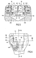
- la figure 3 est une vue selon la flèche III de la figure 2 ;
- la figure 4 est une vue en coupe selon la ligne IV-IV de la figure 3 ;
- les figures 5, 6 et 7 correspondent respectivement aux figures 2, 3 et 4 pour la position serrée des mâchoires de la pince ;
- la figure 8 montre schématiquement un collier de serrage serré à l'aide de la pince conforme à l'invention ; et
- la figure 9 est une vue schématique et partielle selon la flèche IX de la figure 1.
Claims (13)
- Pince destinée à serrer un collier de serrage (28 ; 28') qui présente deux portions terminales (28A, 28B ; 28'A, 28'B) respectivement munies d'une saillie radiale dénommée oreille (30) et d'un crochet (29) apte à être accroché sur ladite oreille pour réaliser le serrage du collier, la pince comprenant deux mâchoires (18 ; 20) respectivement aptes à coopérer avec l'oreille et avec le crochet et à être rapprochées l'une de l'autre pour accrocher le crochet sur l'oreille,
caractérisée en ce que au moins une première mâchoire (18 ; 20) est équipée d'un organe de retenue (45 ; 46) mobile par rapport à elle entre une position de retenue (Fig. 3) dans laquelle cet organe de retenue est apte à coopérer avec au moins l'un des éléments constitués par l'oreille (30) et par le crochet (29) pour retenir ledit élément contre ladite mâchoire et une position de relâchement (Fig: 6) dans laquelle il libère ledit élément par rapport à cette mâchoire. - Pince selon la revendication 1, caractérisée en ce que la première mâchoire (18 ; 20) comporte une surface d'appui (43 ; 44) tournée vers la deuxième mâchoire (20 ; 18) et en ce que l'organe de retenue (45 ; 46) est disposé au-delà de cette surface d'appui dans le sens allant vers ladite deuxième mâchoire.
- Pince selon la revendication 1 ou 2, caractérisée en ce que l'organe de retenue (45 ; 46) est mobile transversalement (T) à la direction (D) dans laquelle les mâchoires (18 ; 20) sont déplacées pour être rapprochées ou éloignées l'une de l'autre.
- Pince selon l'une quelconque des revendications 1 à 3, caractérisée en ce qu'elle comporte des moyens de rappel élastique (52) sollicitant l'organe de retenue (45 ; 46) en permanence vers sa position de retenue.
- Pince selon l'une quelconque des revendications 1 à 4, caractérisée en ce qu'elle comporte un organe de sollicitation (53 ; 54) apte, lors du serrage de la pince, à coopérer avec l'organe de retenue (45 ; 46) pour solliciter ledit organe de retenue vers sa position de relâchement (Fig. 6).
- Pince selon l'une quelconque des revendications 1 à 5, caractérisée en ce que l'organe de retenue est formé par un levier (45 ; 46) monté pivotant (A45 ; A46) sur la première mâchoire (18 ; 20).
- Pince selon l'une quelconque des revendications 1 à 6, caractérisée en ce que les mâchoires (18 ; 20) sont montées sur, respectivement, un premier et un deuxième bras de support (14 ; 16) en étant aptes à pivoter par rapport à ces bras autour d'un axe d'orientation (B) sensiblement parallèle à la direction (D) dans laquelle les mâchoires sont déplacées pour être rapprochées ou éloignées l'une de l'autre.
- Pince selon la revendication 7, caractérisée en ce qu'elle comporte des moyens (80) pour solidariser les deux mâchoires (18 ; 20) en rotation dans leur pivotement autour de l'axe d'orientation (B).
- Pince selon la revendication 8, caractérisée en ce que les deux mâchoires sont solidarisées en rotation par un axe de liaison articulé (80), apte à adopter une configuration d'extension (Fig. 2) lorsque les mâchoires (18 ; 20) sont écartées et une configuration de repli (Fig. 5) lorsque les mâchoires sont serrées l'une contre l'autre.
- Pince selon la revendication 9, caractérisée en ce que l'axe de liaison (80) comprend un tronçon d'axe rigide (82) relié à chacune des deux mâchoires (18 ; 20) par une bielle (84 ; 86).
- Pince selon la revendication 5 et selon la revendication 9 ou 10, caractérisée en ce que l'organe de sollicitation (53 ; 54) est solidaire de l'axe de liaison (80).
- Pince selon l'une quelconque des revendications 1 à 11, caractérisée en ce que les deux mâchoires (18 ; 20) sont identiques.
- Ensemble d'une pince selon l'une quelconque des revendications 1 à 12 et d'un collier de serrage (28) destiné à être serré à l'aide d'une pince,
caractérisé en ce que l'oreille (30) comprend deux plis (30B ; 30C) écartés l'un de l'autre de manière à ménager entre eux un dégagement (30') dans lequel l'organe de retenue (45, 46) est apte à être introduit.
Applications Claiming Priority (3)
| Application Number | Priority Date | Filing Date | Title |
|---|---|---|---|
| FR0006052A FR2808714B1 (fr) | 2000-05-12 | 2000-05-12 | Pince pour serrer un collier |
| FR0006052 | 2000-05-12 | ||
| PCT/FR2001/001423 WO2001085396A1 (fr) | 2000-05-12 | 2001-05-11 | Pince pour serrer un collier |
Publications (2)
| Publication Number | Publication Date |
|---|---|
| EP1280633A1 EP1280633A1 (fr) | 2003-02-05 |
| EP1280633B1 true EP1280633B1 (fr) | 2005-11-02 |
Family
ID=8850143
Family Applications (1)
| Application Number | Title | Priority Date | Filing Date |
|---|---|---|---|
| EP01931831A Expired - Lifetime EP1280633B1 (fr) | 2000-05-12 | 2001-05-11 | Pince pour serrer un collier |
Country Status (8)
| Country | Link |
|---|---|
| EP (1) | EP1280633B1 (fr) |
| JP (1) | JP2004515368A (fr) |
| KR (1) | KR20020097265A (fr) |
| AU (1) | AU2001258523A1 (fr) |
| BR (1) | BR0110494A (fr) |
| DE (1) | DE60114601T2 (fr) |
| FR (1) | FR2808714B1 (fr) |
| WO (1) | WO2001085396A1 (fr) |
Family Cites Families (6)
| Publication number | Priority date | Publication date | Assignee | Title |
|---|---|---|---|---|
| US2747446A (en) * | 1953-07-08 | 1956-05-29 | George J Eder | Pliers with pivotally attached cam actuated supplementary jaws |
| US3216291A (en) * | 1964-04-07 | 1965-11-09 | K D Mfg Co | Hose-clamp deforming pliers |
| US3872747A (en) * | 1974-01-10 | 1975-03-25 | Amerace Corp | Hand tool for installing wire fabric fence clamps |
| US4610187A (en) * | 1985-11-22 | 1986-09-09 | Wittek Industries, Inc. | Tool for applying and removing a spring clamp |
| US4633558A (en) * | 1986-02-27 | 1987-01-06 | Wittek Industries, Inc. | Cam action tool for applying a spring clamp |
| DE9216463U1 (de) * | 1992-12-03 | 1993-01-14 | Hazet-Werk Hermann Zerver Gmbh & Co Kg, 5630 Remscheid | Federbandschellenzange |
-
2000
- 2000-05-12 FR FR0006052A patent/FR2808714B1/fr not_active Expired - Fee Related
-
2001
- 2001-05-11 JP JP2001582035A patent/JP2004515368A/ja active Pending
- 2001-05-11 KR KR1020027015183A patent/KR20020097265A/ko not_active Withdrawn
- 2001-05-11 EP EP01931831A patent/EP1280633B1/fr not_active Expired - Lifetime
- 2001-05-11 DE DE60114601T patent/DE60114601T2/de not_active Expired - Lifetime
- 2001-05-11 WO PCT/FR2001/001423 patent/WO2001085396A1/fr not_active Ceased
- 2001-05-11 AU AU2001258523A patent/AU2001258523A1/en not_active Abandoned
- 2001-05-11 BR BR0110494-2A patent/BR0110494A/pt not_active Application Discontinuation
Also Published As
| Publication number | Publication date |
|---|---|
| BR0110494A (pt) | 2003-04-01 |
| DE60114601D1 (de) | 2005-12-08 |
| AU2001258523A1 (en) | 2001-11-20 |
| KR20020097265A (ko) | 2002-12-31 |
| JP2004515368A (ja) | 2004-05-27 |
| FR2808714B1 (fr) | 2002-09-06 |
| DE60114601T2 (de) | 2006-08-10 |
| FR2808714A1 (fr) | 2001-11-16 |
| EP1280633A1 (fr) | 2003-02-05 |
| WO2001085396A1 (fr) | 2001-11-15 |
Similar Documents
| Publication | Publication Date | Title |
|---|---|---|
| EP1281878B1 (fr) | Axe de liaison pivot entre deux pièces | |
| CA2679079C (fr) | Dispositif de serrage a bras de manoeuvre escamotable et appareil comportant un tel dispositif | |
| EP0847710B1 (fr) | Articulation a ressort pour article de chevelure | |
| EP0077277A1 (fr) | Procédé et dispositif d'application de pinces hémostatiques et pinces hémostatiques appliquées par ce dispositif | |
| FR2663889A1 (fr) | Dispositif d'articulation d'un dossier demontable de siege arriere de vehicule. | |
| EP0145556A1 (fr) | Dispositif de montage et de fixation d'une lampe, notamment pour projecteur d'automobile | |
| FR2761452A1 (fr) | Collier de serrage pour le raccordement de deux tubes | |
| EP0669225A1 (fr) | Porte-cycle et son dispositif de fixation d'un cycle | |
| EP2389264B1 (fr) | Mandrin porte-outil pour l'équipement d'une machine tournante | |
| EP2316678A1 (fr) | Dispositif d'assistance pour la pose d'un pare-brise ou similaire | |
| FR2808714A1 (fr) | Pince pour serrer un collier | |
| FR2622138A1 (fr) | Outil de prehension notamment pour une fiche de connecteur de cable par telemanipulation | |
| FR2765532A1 (fr) | Systeme d'articulation d'un element rabattable de siege arriere sur un vehicule automobile | |
| EP1541791A1 (fr) | Dispositif de maintien d'une béquille de support d'un capot de véhicule automobile | |
| FR2767736A1 (fr) | Dispositif de pince pousse-bague utilise dans le domaine de la plomberie pour l'emboitement des tuyaux en matiere plastique ou en complexe plastique-aluminium sur des raccords | |
| FR2663888A1 (fr) | Articulation pour le basculement d'une assise demontable de siege arriere de vehicule. | |
| FR2654603A1 (fr) | Dispositif pince-nappe. | |
| EP1191174B1 (fr) | Dispositif de sécurité pour crochets de volet | |
| FR2956051A1 (fr) | Mandrin porte-outil pour l'equipement d'une machine tournante | |
| EP0867132B1 (fr) | Fermoir de type automatique notamment pour bracelet-montre | |
| EP1818459B1 (fr) | Dispositif de fermeture d'un cadre par un élément de couronnement verrouillable élastiquement au cadre | |
| FR2867407A1 (fr) | Pince pour decoupe des tubes en matiere plastique | |
| EP0836994B1 (fr) | Pince de traction pour lanière, en particulier pour collier de serrage | |
| EP1280632A1 (fr) | Pince demultipliee | |
| FR3002876A1 (fr) | Agencement de couteau pliant |
Legal Events
| Date | Code | Title | Description |
|---|---|---|---|
| PUAI | Public reference made under article 153(3) epc to a published international application that has entered the european phase |
Free format text: ORIGINAL CODE: 0009012 |
|
| 17P | Request for examination filed |
Effective date: 20021108 |
|
| AK | Designated contracting states |
Designated state(s): AT BE CH CY DE DK ES FI FR GB GR IE IT LI LU MC NL PT SE TR |
|
| AX | Request for extension of the european patent |
Extension state: AL LT LV MK RO SI |
|
| RBV | Designated contracting states (corrected) |
Designated state(s): AT BE CH CY DE FR GB IT LI |
|
| GRAP | Despatch of communication of intention to grant a patent |
Free format text: ORIGINAL CODE: EPIDOSNIGR1 |
|
| RBV | Designated contracting states (corrected) |
Designated state(s): DE FR GB IT |
|
| GRAS | Grant fee paid |
Free format text: ORIGINAL CODE: EPIDOSNIGR3 |
|
| GRAA | (expected) grant |
Free format text: ORIGINAL CODE: 0009210 |
|
| AK | Designated contracting states |
Kind code of ref document: B1 Designated state(s): DE FR GB IT |
|
| REG | Reference to a national code |
Ref country code: GB Ref legal event code: FG4D Free format text: NOT ENGLISH |
|
| REF | Corresponds to: |
Ref document number: 60114601 Country of ref document: DE Date of ref document: 20051208 Kind code of ref document: P |
|
| GBT | Gb: translation of ep patent filed (gb section 77(6)(a)/1977) |
Effective date: 20060208 |
|
| PLBE | No opposition filed within time limit |
Free format text: ORIGINAL CODE: 0009261 |
|
| STAA | Information on the status of an ep patent application or granted ep patent |
Free format text: STATUS: NO OPPOSITION FILED WITHIN TIME LIMIT |
|
| 26N | No opposition filed |
Effective date: 20060803 |
|
| PGFP | Annual fee paid to national office [announced via postgrant information from national office to epo] |
Ref country code: GB Payment date: 20080506 Year of fee payment: 8 |
|
| GBPC | Gb: european patent ceased through non-payment of renewal fee |
Effective date: 20090511 |
|
| PG25 | Lapsed in a contracting state [announced via postgrant information from national office to epo] |
Ref country code: GB Free format text: LAPSE BECAUSE OF NON-PAYMENT OF DUE FEES Effective date: 20090511 |
|
| PGFP | Annual fee paid to national office [announced via postgrant information from national office to epo] |
Ref country code: FR Payment date: 20100608 Year of fee payment: 10 |
|
| REG | Reference to a national code |
Ref country code: FR Ref legal event code: ST Effective date: 20120131 |
|
| PG25 | Lapsed in a contracting state [announced via postgrant information from national office to epo] |
Ref country code: FR Free format text: LAPSE BECAUSE OF NON-PAYMENT OF DUE FEES Effective date: 20110531 |
|
| PGFP | Annual fee paid to national office [announced via postgrant information from national office to epo] |
Ref country code: DE Payment date: 20200513 Year of fee payment: 20 |
|
| PGFP | Annual fee paid to national office [announced via postgrant information from national office to epo] |
Ref country code: IT Payment date: 20200511 Year of fee payment: 20 |
|
| REG | Reference to a national code |
Ref country code: DE Ref legal event code: R071 Ref document number: 60114601 Country of ref document: DE |