EP1280631B1 - Porous abrasive article having ceramic abrasive composites, methods of making, and methods of use - Google Patents
Porous abrasive article having ceramic abrasive composites, methods of making, and methods of use Download PDFInfo
- Publication number
- EP1280631B1 EP1280631B1 EP01926948A EP01926948A EP1280631B1 EP 1280631 B1 EP1280631 B1 EP 1280631B1 EP 01926948 A EP01926948 A EP 01926948A EP 01926948 A EP01926948 A EP 01926948A EP 1280631 B1 EP1280631 B1 EP 1280631B1
- Authority
- EP
- European Patent Office
- Prior art keywords
- abrasive
- composites
- composite
- article
- abrasive article
- Prior art date
- Legal status (The legal status is an assumption and is not a legal conclusion. Google has not performed a legal analysis and makes no representation as to the accuracy of the status listed.)
- Expired - Lifetime
Links
Images


Classifications
-
- B—PERFORMING OPERATIONS; TRANSPORTING
- B24—GRINDING; POLISHING
- B24D—TOOLS FOR GRINDING, BUFFING OR SHARPENING
- B24D3/00—Physical features of abrasive bodies, or sheets, e.g. abrasive surfaces of special nature; Abrasive bodies or sheets characterised by their constituents
- B24D3/02—Physical features of abrasive bodies, or sheets, e.g. abrasive surfaces of special nature; Abrasive bodies or sheets characterised by their constituents the constituent being used as bonding agent
- B24D3/04—Physical features of abrasive bodies, or sheets, e.g. abrasive surfaces of special nature; Abrasive bodies or sheets characterised by their constituents the constituent being used as bonding agent and being essentially inorganic
- B24D3/14—Physical features of abrasive bodies, or sheets, e.g. abrasive surfaces of special nature; Abrasive bodies or sheets characterised by their constituents the constituent being used as bonding agent and being essentially inorganic ceramic, i.e. vitrified bondings
- B24D3/18—Physical features of abrasive bodies, or sheets, e.g. abrasive surfaces of special nature; Abrasive bodies or sheets characterised by their constituents the constituent being used as bonding agent and being essentially inorganic ceramic, i.e. vitrified bondings for porous or cellular structure
-
- C—CHEMISTRY; METALLURGY
- C09—DYES; PAINTS; POLISHES; NATURAL RESINS; ADHESIVES; COMPOSITIONS NOT OTHERWISE PROVIDED FOR; APPLICATIONS OF MATERIALS NOT OTHERWISE PROVIDED FOR
- C09K—MATERIALS FOR MISCELLANEOUS APPLICATIONS, NOT PROVIDED FOR ELSEWHERE
- C09K3/00—Materials not provided for elsewhere
- C09K3/14—Anti-slip materials; Abrasives
- C09K3/1436—Composite particles, e.g. coated particles
Definitions
- the present invention relates to a shaped, three-dimensional abrasive article comprising a plurality of abrasive composites, methods of making the abrasive article, and methods of using the abrasive article to abrade workpiece surfaces. More specifically, the abrasive article includes porosity, wherein the abrasive article has an inter-composite porosity of at least 20% by volume and an intra-composite porosity of at least 5% by volume.
- a shaped, three-dimensional abrasive article comprising abrasive grains and a ceramic binder matrix and having an interconnected porosity of 40% to 80% is known, for example, from US-A-5 738 697.
- Glass articles are found extensively in homes, offices, and factories in the form of lenses, prisms, mirrors, CRT screens, and other items. Many of these glass surfaces are used with optical components which require that the surface be optically clear and have no visible defects and/or imperfections; such a surface finish is often referred to as a mirror finish. If present in or on the surface, defects, imperfections, and even minute scratches may inhibit the optical clarity of the glass article. In some instances, these defects, imperfections, and/or minute scratches may inhibit the ability to accurately see through the glass. Glass surfaces used with optical components, for example, must be essentially free of any defect, imperfection, and/or scratch.
- Articles made from other materials are also found extensively in homes, offices, and factories. Similar to glass articles, these articles often need to have a mirror finish, that is, a surface that is essentially free of any defect, imperfection, and/or scratch. Examples of articles that need a very fine surface finish include magnetic recording items such as hard disk substrates and electronic components such as read-write heads in computers.
- Abrasive finishing processes have been widely used to remove imperfections and/or defects such as mold lines, rough surfaces, small point and other small imperfections in glass and other workpieces.
- the abrasive finishing typically falls within three main processes: grinding, fining, and polishing.
- Grinding steps perfect the desired curve or radius and remove any casting defects by rough grinding the glass surface with an abrasive tool.
- this abrasive tool contains superabrasive particles such as a diamond, tungsten carbide, or cubic boron nitride.
- the abrasive tool in this rough grinding process will impart coarse scratches to the glass or other surface such that resulting surface is neither precise enough nor smooth enough to directly polish to an optically clear state or other desired finish.
- the objective of the grinding process is to remove large amounts of material quickly and fairly accurately while leaving as fine of a scratch pattern as feasible. These scratches are then typically removed by further steps commonly known as "fining” and "polishing".
- Glass fining and polishing is typically done with a loose abrasive slurry which comprises a plurality of abrasive particles dispersed in a liquid medium such as water. Ceramic and many other articles are also polished with a loose abrasive slurry.
- the most common abrasive particles used for loose slurries are pumice, silicon carbide, aluminum oxide, and the like.
- the loose abrasive slurry may optionally contain other additives such as dispersants, lubricants, defoamers, and the like.
- the loose abrasive slurry is pumped between the surface that is being finished and a lap pad, such that the loose abrasive slurry is present between the surface and the lap pad.
- the workpiece and the lap pad will move relative to each other while maintaining contact. This process typically comprises one or more steps, with each step generating a progressively finer surface finish on the workpiece surface.
- What usually is desired is an abrasive article that effectively and economically grinds a surface in a short time period by providing fast stock removal while introducing minimal surface and subsurface damage and scratching.
- the present invention is directed to an abrasive article as described in claims 1 to 5, for polishing, finishing, or otherwise providing a desired finish on a workpieces, such as on hard drive media or disks.
- abrasive articles of the present disclosure provide a fine and scratch-free surface with minimal surface damage.
- the construction of the abrasive article is useful with abrasive particles having an average particle dimension of about 10 micrometers and less, and is especially useful with abrasive particles having an average particle dimension of about 6 micrometers and less. In some embodiments, the abrasive article is useful with abrasive particles having an average particle dimension of about 3 micrometers and less.
- the abrasive article is formed from a plurality of abrasive composites or agglomerates bonded together in a material to create an abrasive article.
- Each composite has a plurality of primary abrasive particles bonded by a first binder matrix; the primary abrasive particles can be individual abrasive particles or aggregates of abrasive particles.
- the abrasive composites act as abrasive particles; when viewed from the perspective of the abrasive composites, each abrasive composite is an abrasive tool or article, and the primary abrasive particles are individual abrasive particles.
- the abrasive article is a three-dimensional abrasive article, having a thickness that is greater than the thickness of one abrasive composite.
- the abrasive article has a thickness that is greater than the thickness of at least 1 abrasive composite, preferably at least 5 abrasive composites, and more preferably is greater than the thickness of at least 10 abrasive composites.
- an abrasive article such as a grinding wheel, is provided by bonding primary, abrasive particles with an inorganic first binder matrix to form abrasive composites. These abrasive composites, in turn, are bonded together to form the abrasive article.
- the abrasive article includes (1) pores disposed within the abrasive composites and (2) between and among the abrasive composites; these porosities are referred to as "intra-composite" porosity and "inter-composite” porosity respectively.
- Typical levels of intra-composite porosity are about 5 to 60 volume percent.
- some level of intra-composite porosity is typically present; it may be desired to introduce additional porosity in some embodiments.
- Inter-composite porosity is between and among the abrasive composites. Typical levels of inter-composite porosity are about 25 to 75 volume percent.
- the ratio of the two porosities can range from about 1:2 to 2:1, or can vary from this.
- the level of intra-composite porosity will differ from the level of inter-composite porosity.
- inter- and intra-composite porosity allows the use of much smaller primary abrasive particles than have been useful in related articles of the art. These articles combine an unusually high cut rate with a fine surface finish.
- the abrasive composites are formed with an inorganic first binder matrix bonding the primary abrasive particles together.
- the composites can be regularly shaped or irregularly shaped.
- inorganic first binder matrix a ceramic matrix or a glass matrix is used.
- primary abrasive particles such as diamond particles, having an average particle dimension of about 0.1 to 1 micrometer, are formed into regularly shaped, cube-like abrasive composites having an average dimension of about 90 micrometers.
- abrasive composites are then bonded, for example, with a second binder material, to form an abrasive article having about 20 to 65% porosity. That is, about 20 to 65% of the volume of the abrasive article is free of both second binder material and abrasive composites.
- the second binder material is an inorganic material, such as a ceramic or a glass.
- the abrasive composites are bonded to form an abrasive article having about 20 to 55% porosity. This porosity may be distributed throughout the abrasive article as any combination of intra-composite and inter-composite porosity.
- the second binder material may be present at a level higher than a preferred level; this may be preferred when the second binder material is a relatively soft, or erodible material.
- the abrasive article can be a unitary article, such as grinding wheel or stone, or can be composed of multiple segments of bonded abrasive composites.
- Figure 1 shows an abrasive article 10 in accordance with the present disclosure.
- the abrasive article 10 of Figure 1 is a shaped, three-dimensional structure 12 in the form of a grinding wheel 15.
- Abrasive article 10 is composed of a plurality of abrasive composites bonded together to form article 10.
- the terms "abrasive composite”, “abrasive agglomerate”, and derivations thereof, are used interchangeably. Each of these terms refers to a plurality of primary abrasive particles bonded together by a first binder matrix to form a unitary particulate mass.
- primary abrasive particle is used to refer to the abrasive particles that are bonded together to form the abrasive composite.
- the primary abrasive particles may be individual abrasive particles or aggregates of particles.
- the abrasive article of the present invention includes a plurality of abrasive composites or agglomerates bonded together by a second binder material to form an abrasive article.
- Inter-composite porosity positioned between and among the abrasive composites, is present in the abrasive article. Also present in the abrasive article is intra-composite porosity, which is within the abrasive composites and is positioned between and among the primary abrasive particles.
- the abrasive composites or agglomerates which provide the overall structure of the abrasive article are constructed from a plurality of primary abrasive particles dispersed in a first binder matrix. Intra-composite porosity, within the abrasive composite between and among the primary abrasive particles, is typically present in the abrasive composite at a level of about 5 to 60 volume percent. ,
- a greatly enlarged portion of abrasive article 10 of Figure 1, designated at "2", is shown.
- the abrasive article 10 comprises a plurality of abrasive composites 20 bonded by second binder material 40 to form a shaped, three-dimensional mass 12.
- Each abrasive composite 20 comprises primary abrasive particles 30 dispersed within first binder matrix 34.
- Composite 20 also includes intra-composite pores 35.
- the abrasive composites can be precisely shaped or irregularly shaped.
- a "precisely or regularly shaped abrasive composite” refers to an abrasive composite having a molded shape that is the inverse of the mold cavity in which the composite was formed: The shape is retained by the composite after the composite has been removed from the mold.
- a precisely or regularly shaped abrasive composite is spherical, such as a solidified droplet.
- the precisely or regularly shaped abrasive composite is substantially free of abrasive particles protruding beyond the exposed surface of the composite before the abrasive article has been used.
- Example methods of making precisely shaped abrasive composites by using molding techniques are described in U.S. Patent Nos. 5,152,917 (Pieper et al.) and 5,975,988 (Christianson).
- An "irregularly shaped abrasive composite” refers to an abrasive composite having a non-precise or irregular shape. The shape is formed, for example, by crushing a larger particle to form the irregularly shaped abrasive composite.
- a combination of precisely and irregularly shaped composites can be present in an abrasive article.
- the precisely shaped composites are about the same size.
- Irregularly shaped abrasive composites are typically graded according to their size to provide a relatively uniform abrasive composite size within a given abrasive article.
- the precisely or regularly shaped composites generally have a precise geometric shape. Initially, a plurality of primary abrasive particles generally will be present on the surface of the composite; it is preferred that the primary abrasive particles do not protrude beyond the surface of the abrasive composite. As the abrasive article is used to abrade a workpiece, the first binder matrix breaks down to reveal new abrasive particles. By the abrasive composite eroding and revealing new abrasive particles, the abrasive composite, and the overall abrasive article, is providing a self-dressing function; that is, the abrasive article is exposing fresh abrasive particles during the grinding process.
- the shape of the abrasive composite may be selected from any number of geometric shapes, for example, cubic, block-like, cylindrical, prismatic, pyramidal, truncated pyramidal, conical, truncated conical, spherical, or any three-dimensional shape.
- the shape although precise, can be irregular; for example, the cross-sectional shape of the base maybe different than the top surface.
- Another useable shape is hemispherical, which is described in U.S. Patent No. 5,681,217 (Hoopman et al.).
- the abrasive composites may have any frustum shape; a frustum being defined as the parts of a solid figure between two planes bisecting that solid figure; often, the two planes are parallel. It is generally preferred to have a relatively constant surface area of contact between the workpiece surface and the abrasive article as the abrasive article wears.
- the abrasive article can have a mixture of different abrasive composite shapes and/or dimensions; however, it is generally preferred that abrasive composites having generally the same dimension are used in a given abrasive article.
- the average dimension of the abrasive composites should be at least about 5 micrometers. Alternately or additionally, the average dimension of the abrasive composites is no greater than about 1000 micrometers. Typically the abrasive composite has an average dimension of about 10 to 800 micrometers, preferably about 20 to 600 micrometers. A general rule is that the abrasive composite has a median dimension that is at least 3 times larger than the largest linear dimension of the primary abrasive particles within the composite, preferably at least 5 times larger.
- the primary abrasive particles used in the abrasive composites of the abrasive article of the present disclosure can be any abrasive particle.
- the primary abrasive particles can be individual abrasive particles or can be aggregates or agglomerates of individual abrasive particles.
- the primary abrasive particles, in particular aggregates of individual particles have minimal, if any, second binder material providing the structure of the aggregate. Aggregates of individual abrasive particles may be held together, for example, by mechanical interaction between the particles or by intra-particle forces, such as Van der Waal's forces.
- the primary abrasive particles preferably have an average particle dimension of preferably about 1 micrometer to about 10 micrometers. Occasionally, abrasive particle sizes are reported as “mesh” or “grade”, both of which are commonly known abrasive particle sizing methods.
- the abrasive article of the present disclosure is particularly useful with primary abrasive particles having an average particle dimension of about 10 micrometers and less, and is especially useful with primary abrasive particles having an average particle dimension of about 6 micrometers and less. Additionally, primary abrasive particles having an average particle dimension of about 3 micrometers and less can be easily formulated into abrasive articles in accordance with the present disclosure.
- the primary abrasive particles within an abrasive composite are generally all from the same mesh or grade; they generally fall within a standard bell-curve distribution of particle sizes with a central average particle dimension.
- a bimodal distribution of particles sizes can be used.
- a bimodal distribution can be achieved, for example, by mixing an amount of primary abrasive particles having an average particle dimension of about 10 micrometers with an amount of primary abrasive particles having an average particle dimension of about 3 micrometers. It is preferred that no matter what particle size distribution is used for the primary abrasive particles, that the particles within the composite do not overly pack together and unacceptably reduce the intra-porosity within the composite.
- the abrasive particles have a Mohs hardness of at least 8, more preferably at least 9.
- suitable abrasive particles include aluminum oxide, including fused aluminum oxide, heat treated aluminum oxide, white fused aluminum oxide, ceramic aluminum oxide (such as sol gel derived alumina), black silicon carbide, green silicon carbide, titanium diboride, boron carbide, silicon nitride, tungsten carbide, titanium carbide, garnet, fused alumina zirconia, diamond, cubic boron nitride, hexagonal boron nitride, and the like.
- the diamond and boron nitride abrasive particles may be monocrystalline or polycrystalline.
- alumina-based sol gel derived abrasive particles can be found in U.S. Patent Nos. 4,314,827 (Leitheiser et al.); 4,623,364 (Cottringer); 4,744,802 (Schwabel); 4,770,671 (Monroe); and 4,881,951 (Monroe et al).
- the sol gel derived alumina abrasive particle may contain a metal oxide modifier.
- diamond abrasive particles are preferred.
- the diamond abrasive particles may be natural or synthetically made diamond; the diamonds may be "resin bond diamonds", “saw blade grade diamonds", or “metal bond diamonds".
- the diamond abrasive particles may have a blocky shape associated with them, or alternatively, a needle like shape.
- the single diamond particles can contain a surface coating such as a metal coating (for example, nickel, aluminum, copper or the like), an inorganic coating (for example, silica), or an organic coating.
- An example of polycrystalline diamond particles is commercially available from Mypodiamond Inc. under the trade designation "Mypolex”.
- Mypolex Mypolex
- the abrasive article of the invention can contain a blend of diamond particles with other abrasive particles.
- the abrasive composites are about 10 to 90 percent by weight primary abrasive particles and 90 to 10 percent first binder matrix. Typically, the abrasive composites are about 15 to 85 percent primary abrasive particles and 85 to 15 percent first binder matrix.
- a first binder matrix holds the primary abrasive particles together; together, the primary abrasive particles and first binder matrix form the abrasive composite.
- the binder is a "ceramic binder", which includes ceramics, glass-ceramics, and glasses (also referred to as vitreous or vitrified binders). These materials generally fall within the same category when considering atomic structure.
- the bonding of the adjacent atoms is the result of process of electron transfer or electron shaping. Alternatively, weaker bonds as a result of attraction of positive and negative charge, known as secondary charge, can exist.
- Crystalline ceramics, glass and glass-ceramics have ionic and covalent bonding. Ionic bonding is achieved as a result of electron transfer from one atom to another. Covalent bonding is the result of sharing valence electrons and is highly directional. By way of comparison, the primary bond in metals is known as a metallic bond and involves non-directional sharing of electrons.
- Crystalline ceramics can be subdivided into silica-based (silicates such as fireclay, mullite, porcelain, and Portland cement), non-silicate oxides (such as alumina, magnesia, MgAl 2 O 4 , and zirconia), and non-oxide ceramics (such as carbides, nitrides, and graphite).
- silica-based silicates such as fireclay, mullite, porcelain, and Portland cement
- non-silicate oxides such as alumina, magnesia, MgAl 2 O 4 , and zirconia
- non-oxide ceramics such as carbides, nitrides, and graphite.
- Non-crystalline glasses are comparable in composition with crystalline ceramics. As a result of specific processing techniques, these materials do not have the long range order that crystalline ceramics have. Glass-ceramics are the result of controlled heat-treatment to produce over 90% crystalline phase or phases with the remaining non-crystalline phase filling the grain boundaries. Glass ceramics combine the advantage of both ceramics and glasses and offer durable mechanical and physical properties.
- Preferred first binder matrixes are glasses that include metals oxides, for example, aluminum oxide, boron oxide, silicon oxide, magnesium oxide, sodium oxide, manganese oxide, zinc oxide, and mixtures thereof.
- a preferred ceramic matrix is alumina-borosilicate glass comprising Si 2 O, B 2 O 3 , and Al 2 O 3 .
- a preferred alumina-borosilicate glass comprises, by weight, about 18% B 2 O 3 , 8.5% Al 2 O 3 , 2.8% BaO, 1.1% CaO, 2.1% Na 2 O, 1.0% Li 2 O, with the balance being Si 2 O.
- Such an alumina-borosilicate glass, having a particle size of less than about 45 mm, is commercially available from Specialty Glass Incorporated, Oldsmar, FL.
- the abrasive composites are generally made by mixing together a temporary binder, a first binder matrix precursor, abrasive particles, and a sufficient amount of solvent, typically water, to facilitate molding the ingredients.
- the resulting mixture is a moldable paste or slurry.
- This moldable slurry is placed into a suitable mold, dried, and the at least partially hardened abrasive composite precursors are removed.
- the abrasive composite precursors are then converted to abrasive composites, for example, by firing or sintering the composite precursors.
- the abrasive composites of the abrasive articles of the present disclosure are porous and preferably have a measurable porosity.
- the term "porous" can be used to describe either or both the structure of the abrasive composite, which is characterized by having pores or voids distributed throughout the abrasive composite among the abrasive particles, or the structure of the abrasive article, which is characterized by having pores or voids distributed through its mass among the abrasive composites.
- intra-composite porosity is the porosity distributed throughout the abrasive composite
- inter-composite porosity is the porosity distributed among the abrasive composites.
- either or both of the "intra-composite porosity" and the “inter-composite porosity” may be positioned wholly within the first binder matrix (for intra-composite) and the second binder material (for inter-composite).
- the intra-composite porosity extends between and among the primary abrasive particles, and can be open to the external surface of the composite or can be sealed within the composite.
- the pores may be defined by both primary abrasive particles and first binder matrix, or wholly by first binder matrix. Intra-composite porosity is believed to modify the mechanical properties of the composite and to aid in the controlled breakdown of the abrasive composites leading to a release of used (i.e., dull) abrasive particles from the composites.
- the pores in the composites may increase the performance (e.g., the cut rate and/or surface finish) of the final abrasive article by providing a path for removal of swarf and used abrasive particles from the interface between the abrasive article and the workpiece. Pores also facilitate coolant and lubricant transport to the grinding or polishing interface.
- the intra-composite porosity occupies at least about 5% of the volume of the composite.
- the pores occupy no greater than about 70% of the volume of the composite.
- the pores occupy about 5% to 60% of the volume, preferably about 6% to 50%.
- a porous first binder matrix can be formed by well known techniques, for example, by controlled firing of a matrix precursor or by the inclusion of pore forming agents, such as glass bubbles, in the matrix precursor.
- Composites having high levels of intra-composite porosity generally require a first binder matrix having a high mechanical strength.
- the abrasive composites may further contain other additives such as fillers, grinding aids, pigments, adhesion promoters, cutting aids, and other processing materials. These additives may be positioned within the pores of the composite, be provided as coatings on the primary abrasive particles, or be dispersed throughout the first binder matrix.
- individual diamond particles having an average particle dimension of about 0.1 micrometer, are formed into abrasive composites with an alumina-borosilicate first binder matrix.
- the abrasive composites with a composite porosity of about 29%, have a truncated pyramidal shape with an average dimension of about 90 micrometers.
- individual diamond particles having an average particle dimension of about 1.5 micrometers, are formed into abrasive composites with an alumina-borosilicate first binder matrix.
- the abrasive composites with a composite porosity of about 5-10%, have a truncated pyramidal shape with an average dimension of about 90 micrometers.
- a method for making an abrasive composite or agglomerate useful in the abrasive article of the present disclosure comprises, for example, mixing starting materials comprising a first binder matrix precursor, abrasive particles, and a temporary organic binder precursor.
- the first binder matrix precursor will be converted to the first binder matrix.
- the temporary organic binder precursor permits the mixture to be more easily shaped and to retain this shape during further processing; typically, the temporary organic binder precursor is sacrificed (e.g., burned off) during the final steps of making the abrasive composite.
- additives and processing aids e.g., inorganic fillers, grinding aids, and/or a liquid medium may be used.
- the abrasive particles are mixed thoroughly with a temporary organic binder precursor in a mechanical mixing device such as a planetary mixer.
- the binder precursor is then added to the resulting mixture and blended until a homogeneous mixture is achieved, typically 10 to 30 minutes.
- the preferred method for mixing the abrasive particles and binder precursor can be to use an ultrasonic bath, for a typical period of about 20 to 30 minutes, with the help of an ultrasonic cleaner (such as available from Branson or Cole-Palmer), which vibrate at approximately 47,000 to 50,000 cycles per second.
- the mixture resembles a paste or slurry that is then shaped and processed to form composite precursors.
- the mixture may be shaped, for example, by molding, extrusion, and die cutting.
- the mixture may alternately be shaped by passing it through a screen, or coating it onto a web using a rotogravure roll, for example.
- the shaping process can be done in a batch process or in a continuous manner.
- One preferred technique for shaping the abrasive composite is to place the starting materials, which have been combined and formed into a homogenous mixture, into a flexible mold.
- the flexible mold can be any mold which allows for easy release of the particles, for example, a silicone or polypropylene mold. Additionally, the mold may contain a release agent to aid in the removal of the dried composites.
- the mold, containing the mixture is then placed in an oven and heated to at least partially remove any liquid. The temperature depends on the temporary organic binder precursor that may be used, and is typically between 35 to 200 °C, preferably, 70 to 150°C.
- the at least partially dried or hardened mixture is then removed from the mold. It is also possible to completely destroy, i.e., completely burn off the mold, to release the composites.
- the abrasive composites can include a coating of inorganic particles to increase the surface area and also minimize the aggregation of the abrasive composites with one another during their manufacture.
- One method to achieve the coating is to mix the composite precursors after they are shaped, e.g., removed from the mold, with the inorganic particles in order to apply the inorganic particles, e.g. abrasive particles, to the composite precursor.
- the composite precursors are then heated to burn off any organic materials used to prepare the composite precursors, for example, the temporary organic binder, and to melt or vitrify the inorganic binder; this may occur separately or as one continuous step.
- the temperature and rate of heating to burn off the organic materials is selected to avoid excessive bubbles which may result in undesirably sized pores in the abrasive composite and gerierally depends on the chemistry of the optional ingredients including the temporary organic binder precursor.
- the temperature for burning off organic materials ranges from about 100 to 600 °C, preferably from 200 to 500 °C, although higher temperatures are usable.
- the temperature for melting or vitrifying the inorganic binder typically ranges between 600 to 1150 °C, preferably between 600 to 950 °C.
- the binder may not be fully vitrified or hardened; rather, only a partial vitrification or hardening may be done.
- the resulting composites can then be thermally processed to optimize bond properties.
- the thermal processing comprises heating at a temperature ranging from 300 to 900 °C, preferably 350 to 800 °C, and more preferably 400 to 700 °C.
- the abrasive composites are molded to form a three dimensional abrasive article, such as abrasive article 10 in Figure 1 and abrasive article 50 in Figure 6.
- the abrasive article is a three-dimensional abrasive article; that is, the thickness of the abrasive composites within the article is typically greater than the thickness of a mono-layer of abrasive composites.
- the thickness of the layer of the abrasive composites is greater than the largest dimension of one abrasive composite.
- the thickness of the layer of abrasive composites is greater than 5 times the largest dimension of the abrasive composites, more preferably greater than 10 times the largest dimension of the abrasive composites.
- the abrasive article can be a single piece, such as grinding wheel 15 of Figure 1, or the abrasive article can be made from a plurality of segments 52, such as shown in abrasive article 50 of Figure 6.
- segments 52 each occupy a portion of the circumference of hub 54.
- An axial hole 55 is used to mount the abrasive article 50 on a spindle or the like.
- the abrasive article, or a portion of the abrasive article is formed by molding or otherwise bonding a plurality of abrasive composites or agglomerates together into a shaped mass. Typically, this is done by the application of heat and pressure while the abrasive composites are retained within a mold. Such molding techniques are well known.
- the abrasive composites may be only at least partially dried, hardened or vitrified, or may be fully hardened or vitrified. If a non-fully hardened or vitrified abrasive composite is molded to form the final abrasive article, it is desired that the level of intra-composite porosity within the composite changes no more than about 5%, preferably no more than 2% from the prior-to-molding level to the after-molding level. Further, the abrasive composite retains its form, e.g., its shape and size, during the molding process. The abrasive composite does not loose its individual integrity once incorporated into the abrasive article.
- the abrasive composites are molded to form the abrasive article in accordance with the present disclosure, and typically a second binder material is added to facilitate the bonding together of the composites.
- the amount of second binder material is preferably minimal, so that the second binder material is located between the abrasive composites, with volumes devoid of second binder material and composites, thus creating inter-composite porosity.
- Examples of usable second binder materials include organic second binder materials (such as phenolics, acrylates, polyamides, and the like) and inorganic second binder materials.
- examples of inorganic second binder materials include metal binders (such as nickel) and ceramic second binder materials.
- the second binder material is a "ceramic binder".
- the term "ceramic binder” is loosely used to include ceramics, glass-ceramics, and glasses (also referred to as vitreous or vitrified).
- Refractory particles may be combined with a glass to form a binder composite; such particles typically are used to modify the coefficient of thermal expansion, the melt viscosity, and the mechanical properties of the binder material.
- second binder material 40 bonds abrasive composites 20 together to form the shaped, three-dimensional article 12. Second binder material 40, together with abrasive composites 20, define inter-composite pores 45. In Figure 2, composites 20 are dispersed randomly throughout abrasive article 10.
- abrasive composites 20, with primary abrasive particles 30 bonded within first binder matrix 34 and having intra-composite pores 35, are bonded by second binder material 40 in an ordered, geometric pattern, similar to a checkerboard pattern. Inter-composite pores 45 are defined by second binder material 40 and composites 20.
- Figure 3 shows a single layer of bonded composites 20; it is understood that this geometric pattern can continue throughout the depth of the abrasive article. Any pattern of abrasive composites, such as shown in Figure 3, can be continued throughout the depth of the abrasive article.
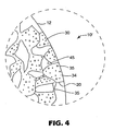
- no extra second binder material is used to bond the composites together to form the abrasive article; rather, the first binder matrix of the abrasive composites themselves bonds the composites together. See, for example, abrasive article 10' in Figure 4, where first binder matrix 34, that which binds the individual abrasive particles 30 within composites 20, also binds multiple composites 20 together.
- First binder matrix 34 defines inter-composite pores 45, and may also define intra-composite pores 35.
- Abrasive article 10' without a second binder material (i.e., only having first binder matrix 34 and no second binder material 40 as in abrasive article 10 of Figure 2), can be made by heating the abrasive composites to a temperature so that first binder matrix 34 begins to flow and fuse the composites together.
- the complete firing of the composites, and the firing of the abrasive article are accomplished in a single heating step. It is understood that during the single heating step, the composites retain their integrity (e.g., shape, size, intra-composite porosity, etc.).
- FIG. 5 Another embodiment is depicted in Figure 5, where abrasive composites 20, with primary abrasive particles 30 bonded within first binder matrix 34 and having intra-composite pores 35, are bonded in an ordered, geometric pattern.
- Composites 20 are bonded together by first binder matrix 34, the same as provides the structure is composites 20.
- Inter-composite pores 45 are defined by composites 20.
- Figure 5 shows a single layer of bonded composites 20; it is understood that this geometric pattern can continue throughout the depth of the abrasive article.
- the abrasive article of the present disclosure is porous and preferably has a measurable porosity.
- the term "porous" can be used to describe either or both the structure of the abrasive composite, which is characterized by having pores or voids distributed throughout its mass, or the structure of the abrasive article, which is characterized by having pores or voids distributed among and between the abrasive composites.
- the pores are defined by the abrasive composites and any second binder material that may be present.
- the pores are void of any material.
- it is preferred that the majority of the porosity of the abrasive article is inter-composite porosity; that is, that majority of the porosity is between the composites rather than within the composites.
- the inter-composite pores within the abrasive article extend between and among the abrasive composites and any second binder material, and can be open to the external surface of the abrasive article or can be sealed. Pores within the abrasive article are believed to aid in the controlled breakdown of the abrasive composites leading to a release of used (i.e., dull) abrasive particles from the composites. Both inter-composite pores and intra-composite pores may increase the performance (e.g., the cut rate and/or surface finish) of the abrasive article by providing a path for the removal of swarf and used abrasive particles from the interface between the abrasive article and the workpiece.
- the inter-composite pores within the abrasive article occupy at least 20% of the volume of the abrasive article.
- the pores occupy no more than about 80%.
- the inter-composite porosity is about 25 to 75%, preferably about 30 to 60%, of the volume of the abrasive article.
- the majority of the porosity within the abrasive article is inter-composite porosity, disposed between the abrasive composites.
- the particular preferred volume percent of inter-composite porosity is dependent on the average particle dimension of the abrasive composites, the dimension of the primary abrasive particles forming the abrasive composites, and the amount of intra-composite porosity. Further, the volume percent of the pores will depend on any second binder material used to bond the abrasive composites together to form the abrasive article.
- the abrasive article should have sufficient strength to be able to withstand the forces exerted during grinding or polishing; the porosity within the abrasive article should not unduly weaken the abrasive article. It should not result in an abrasive article that is significantly weaker than the individual abrasive composites.
- the abrasive articles may further contain other additives such as fillers, grinding aids, pigments, adhesion promoters, cutting aids, and other materials. These additives may be positioned within the inter-composite pores of the composite, be provided as coatings on the abrasive composites, be dispersed throughout the second binder material, or within the inter- or intra-composite pores of the abrasive article.
- individual diamond particles having an average particle dimension of about 0.1 micrometer, are formed into abrasive composites with an alumina-borosilicate first binder matrix.
- the abrasive composites with an intra-composite porosity of about 29%, have a truncated pyramidal shape with an average dimension of about 90 micrometers.
- These abrasive composites are then bonded with an epoxy binder (commercially available as "Epon 828" from Shell) to form an abrasive article having about 33% abrasive composites by volume, 33% organic binder by volume, and 33% inter-composite porosity.
- individual diamond particles having an average particle dimension of about 1 micrometer, are formed into abrasive composites with an alumina-borosilicate first binder matrix.
- the abrasive composites with an intra-composite porosity of about 5-10%, have a truncated pyramidal shape with an average dimension of about 90 micrometers.
- These abrasive composites are placed into a mold, heated to a temperature suitable to cause a portion of the alumina-borosilicate first binder matrix to flow, thereby causing the first binder matrix to bond the composites together. No additional binder is needed to form the abrasive article.
- the resulting abrasive article is about 50% abrasive composites by volume and 50% inter-composite porosity.
- Glass workpieces that are often ground, polished, finished, abraded, fined or otherwise treated with abrasive articles include lenses, prisms, mirrors, CRT screens, windows, automobile and other windshields, hard drive substrates, and other glass items.
- Many various machines, grinders, polishers, and the like can be used to grind glass workpieces with the abrasive articles of the present disclosure. The particular method used to grind the glass workpiece is depending on the type of workpiece and the desired effect.
- the glass workpieces are typically ground by moving at least one of the glass workpiece and the abrasive article in relation to the other. This movement may be rotary, random, linear, or various combinations.
- Rotary motion may be generated by attaching the abrasive article to a rotary tool or by placing the glass workpiece on a rotating holder.
- a random orbital motion may be generated by a random orbital tool, and linear motion may be generated by a continuous abrasive belt.
- the glass surface and abrasive article may rotate in the same direction or opposite directions. Operating rpm may range up to about 4,000 rpm, depending on the abrasive article employed.
- the relative movement between glass and abrasive article may also depend on the dimensions of the glass. If the glass is relatively large, it may be preferred to move the abrasive article during grinding while the glass is held stationary.
- the abrasive article and the glass surface preferably have an interface pressure of about 0.1 kg/cm 2 to about 2 kg/cm 2 , more preferably about 0.25 to 1.25 kg/cm 2 , and even more preferably about 0.4 to 0.85 kg/cm 2 . If the force is too high, the abrasive article may not refine the scratch depth but rather increase the scratch depth. Also, the abrasive article may wear excessively. If the force is too low, the abrasive article may not effectively remove sufficient glass material.
- a liquid commonly referred to as a coolant.
- a liquid commonly referred to as a "lubricant”.
- the liquid inhibits heat build up during grinding and removes the swarf from the grinding interface.
- Swarf is the term used to describe the glass debris that is abraded away by the abrasive article. In some instances, the glass swarf may damage the surface of the glass being ground. Thus, it is desirable to remove the swarf from the interface.
- a temporary binder solution was prepared by dissolving 25 parts by weight "Stadex 230" dextrin (obtained from A.E. Stanley Manufacturing Co. of Decatur, IL) in 75 parts de-ionized water.
- the slurry was dried while in the cavities for one hour at room temperature, after which the tool and slurry was placed in an oven at 75 °C for one hour.
- the dried green composite precursors were removed from the tooling by using an ultrasonically driven bar (ultrasonically driven by a model 902R from Branson Ultrasonic Instruments of Danbury, CT).
- the green composite precursors were fired in a refractor sager (obtained from Ipsen Ceramic of Pecatonica, IL). The temperature was ramped up from room temperature to 400 °C at 1.5 °C/min and fired from 1 hour in an oxidizing (air) atmosphere. After firing, the abrasive composites were cooled to room temperature at a temperature decrease of about 2 °C/minute.
- a temporary binder solution was prepared by dissolving 33 parts "Stadex 230" dextrin in 66 parts deionizied water.
- the paste was molded into a cylindrical grinding wheel having an outside diameter of 3.61 cm (1.42 inches), and inside diameter of 2.92 cm (1.15 inches), and a width of 0.72 cm (0.285 inch). The wheel was dried at room temperature and then placed in an oven, where the temperature was raised to 680 °C at a rate of 2 °/minute and held at 680 °C for 2 hours. The wheel was allowed to cool to room temperature.
- the resulting abrasive article was similar to that shown in Figures 1 and 2.
- the abrasive wheel had fine size abrasive particles and an open, porous structure.
Abstract
Description
Claims (10)
- A shaped, three-dimensional abrasive article comprising:wherein the abrasive article has an inter-composite porosity of at least 20% by volume, and an intra-composite porosity of at least 5% by volume.a plurality of three-dimensionally arranged abrasive composites, the abrasive composites comprising:(i) a plurality of primary abrasive particles haying an average particle dimension of no greater than about 10 micrometers; and(ii) a ceramic first binder matrix binding the plurality of abrasive particles to form the abrasive composites;
- The shaped, three-dimensional abrasive article according to claim 1, wherein the intra-composite porosity is about 6 to 50% by volume.
- The shaped, three-dimensional abrasive article according to claim 1, further comprising:(a) a second binder material bonding together the plurality of abrasive composites; and(b) the inter-composite porosity being defined by the second binder material and the abrasive composites.
- The shaped, three-dimensional abrasive article according to claim 1, wherein the abrasive article has an inter-composite porosity of about 25 to 75% by volume.
- The shaped, three-dimensional abrasive article according to claim 1, wherein the abrasive article comprises a plurality of abrasive segments, each abrasive segment comprising:wherein the abrasive article has an inter-composite porosity of at least 20% by volume, and an intra-composite porosity of at least 5% by volume.a plurality of abrasive composites, the abrasive composites comprising:(i) a plurality of primary abrasive particles having an average particle dimension of no greater than about 10 micrometers; and(ii) a ceramic first.binder matrix binding the plurality of abrasive particles to form the abrasive composites;
- A method of making a shaped, three-dimensional abrasive article, comprising:(a) providing a plurality of abrasive composites, the abrasive composites comprising:(i) a plurality of primary abrasive particles having an average particle dimension of no greater than about 10 micrometers; and(ii) a ceramic first binder matrix binding the plurality of abrasive particles to form the abrasive composites;(b) molding the plurality of abrasive composites to form an abrasive article having an inter-composite porosity between the abrasive composites of at least 20% by volume, and an intra-composite porosity of at least 5% by volume of the hardened abrasive composites.
- The method according to claim 6, where the step (a) of providing a plurality of composites comprises:providing a plurality of at least partially hardened composites, the at least partially hardened composites having been at least partially hardened by the application of heat to a plurality of composite precursors.
- The method according to claim 7, wherein the plurality of at least partially hardened composites has an initial intra-composite porosity; and the step of molding the plurality of abrasive composites to form an abrasive article comprises:molding the plurality of at least partially hardened composites to form an abrasive article and to form hardened abrasive composites, the hardened abrasive composites having a final intra-composite porosity of at least 5% by volume of the hardened abrasive composites.
- The method according to claim 6, wherein the step of molding the plurality of abrasive composites to form an abrasive article having a porosity between the abrasive composites of at least 20% by volume comprises:molding the plurality of abrasive composites to form an abrasive article having a porosity between the abrasive composites of 25-75% by volume.
- A method of refining a workpiece surface, comprising:(a) providing an abrasive article as defined in claims 1 to 5 comprising:
a plurality of abrasive composites;(b) contacting a workpiece surface with the plurality of abrasive composites; and(c) moving the abrasive article and workpiece surface in relation to one another.
Applications Claiming Priority (3)
| Application Number | Priority Date | Filing Date | Title |
|---|---|---|---|
| US20262600P | 2000-05-09 | 2000-05-09 | |
| US202626P | 2000-05-09 | ||
| PCT/US2001/012061 WO2001085393A1 (en) | 2000-05-09 | 2001-04-12 | Porous abrasive article having ceramic abrasive composites, methods of making, and methods of use |
Publications (2)
| Publication Number | Publication Date |
|---|---|
| EP1280631A1 EP1280631A1 (en) | 2003-02-05 |
| EP1280631B1 true EP1280631B1 (en) | 2005-08-17 |
Family
ID=22750655
Family Applications (1)
| Application Number | Title | Priority Date | Filing Date |
|---|---|---|---|
| EP01926948A Expired - Lifetime EP1280631B1 (en) | 2000-05-09 | 2001-04-12 | Porous abrasive article having ceramic abrasive composites, methods of making, and methods of use |
Country Status (10)
| Country | Link |
|---|---|
| US (1) | US6702650B2 (en) |
| EP (1) | EP1280631B1 (en) |
| JP (1) | JP2003532550A (en) |
| KR (1) | KR100790062B1 (en) |
| AT (1) | ATE302094T1 (en) |
| AU (1) | AU2001253447A1 (en) |
| BR (1) | BR0110423A (en) |
| CA (1) | CA2408249A1 (en) |
| DE (1) | DE60112740T2 (en) |
| WO (1) | WO2001085393A1 (en) |
Cited By (1)
| Publication number | Priority date | Publication date | Assignee | Title |
|---|---|---|---|---|
| US9393158B2 (en) | 2011-08-25 | 2016-07-19 | Brightwake Limited | Non-adherent wound dressing |
Families Citing this family (112)
| Publication number | Priority date | Publication date | Assignee | Title |
|---|---|---|---|---|
| GB9106317D0 (en) * | 1991-03-25 | 1991-05-08 | Nat Res Dev | Material having a passage therethrough |
| DE60125808T2 (en) * | 2000-10-06 | 2007-10-11 | 3M Innovative Properties Co., St. Paul | CERAMIC AGGREGATE PARTICLES |
| CA2425190C (en) * | 2000-10-16 | 2010-03-02 | 3M Innovative Properties Company | Method of making an agglomerate particle |
| US20030165638A1 (en) * | 2001-07-06 | 2003-09-04 | Louks John W. | Inorganic fiber substrates for exhaust systems and methods of making same |
| KR20100017974A (en) * | 2001-07-06 | 2010-02-16 | 쓰리엠 이노베이티브 프로퍼티즈 컴파니 | Inorganic fiber substrates for exhaust systems and methods of making same |
| US6988937B2 (en) * | 2002-04-11 | 2006-01-24 | Saint-Gobain Abrasives Technology Company | Method of roll grinding |
| GB2420786B (en) * | 2002-04-11 | 2006-10-25 | Saint Gobain Abrasives Inc | Abrasive articles with novel structures and methods for grinding |
| US6679758B2 (en) * | 2002-04-11 | 2004-01-20 | Saint-Gobain Abrasives Technology Company | Porous abrasive articles with agglomerated abrasives |
| US7090565B2 (en) * | 2002-04-11 | 2006-08-15 | Saint-Gobain Abrasives Technology Company | Method of centerless grinding |
| US7544114B2 (en) * | 2002-04-11 | 2009-06-09 | Saint-Gobain Technology Company | Abrasive articles with novel structures and methods for grinding |
| US6797023B2 (en) * | 2002-05-14 | 2004-09-28 | Saint-Gobain Abrasives Technology Company | Coated abrasives |
| WO2005014504A1 (en) * | 2003-01-08 | 2005-02-17 | 3M Innovative Properties Company | Ceramic fiber composite and method for making the same |
| DE102005007661A1 (en) | 2005-02-19 | 2006-08-24 | Rud. Starcke Gmbh & Co. Kg | Grinding wheels and their production |
| US20060276111A1 (en) * | 2005-06-02 | 2006-12-07 | Applied Materials, Inc. | Conditioning element for electrochemical mechanical processing |
| US7883398B2 (en) * | 2005-08-11 | 2011-02-08 | Saint-Gobain Abrasives, Inc. | Abrasive tool |
| US7722691B2 (en) * | 2005-09-30 | 2010-05-25 | Saint-Gobain Abrasives, Inc. | Abrasive tools having a permeable structure |
| US7594845B2 (en) * | 2005-10-20 | 2009-09-29 | 3M Innovative Properties Company | Abrasive article and method of modifying the surface of a workpiece |
| GB0606661D0 (en) | 2006-04-03 | 2006-05-10 | Brightwake Ltd | Improvements relating to dressings |
| US20080014845A1 (en) * | 2006-07-11 | 2008-01-17 | Alpay Yilmaz | Conditioning disk having uniform structures |
| US8740670B2 (en) | 2006-12-28 | 2014-06-03 | Saint-Gobain Ceramics & Plastics, Inc. | Sapphire substrates and methods of making same |
| EP2094439A2 (en) * | 2006-12-28 | 2009-09-02 | Saint-Gobain Ceramics & Plastics, Inc. | Sapphire substrates and methods of making same |
| JP2010514581A (en) * | 2006-12-28 | 2010-05-06 | サン−ゴバン セラミックス アンド プラスティクス,インコーポレイティド | Sapphire substrate and manufacturing method thereof |
| KR101159658B1 (en) * | 2006-12-28 | 2012-06-25 | 생-고뱅 세라믹스 앤드 플라스틱스, 인코포레이티드 | Method of grinding a sapphire substrate |
| EP2505312B1 (en) * | 2007-03-14 | 2015-11-18 | Saint-Gobain Abrasives, Inc. | Method of making a bonded abrasive article |
| CN101678532B (en) * | 2007-03-14 | 2012-07-04 | 圣戈班磨料磨具有限公司 | Bonded abrasive article and method of making |
| US8715037B2 (en) | 2007-09-13 | 2014-05-06 | Vibraglaz (Uk) Limited | Materials processing medium and method |
| GB2468507B (en) * | 2009-03-11 | 2015-04-29 | Vibraglaz Uk Ltd | Abrasive element |
| GB0717849D0 (en) * | 2007-09-13 | 2007-10-24 | Vibraglaz Uk Ltd | Finishing medium and process |
| CN101909823B (en) * | 2007-12-27 | 2012-11-21 | 3M创新有限公司 | Shaped, fractured abrasive particle, abrasive article using same and method of making |
| US8123828B2 (en) * | 2007-12-27 | 2012-02-28 | 3M Innovative Properties Company | Method of making abrasive shards, shaped abrasive particles with an opening, or dish-shaped abrasive particles |
| PL2174751T3 (en) * | 2008-10-10 | 2014-12-31 | Center For Abrasives And Refractories Res & Development C A R R D Gmbh | Abrasive grain agglomerates, method for their manufacture and their application |
| US8142532B2 (en) * | 2008-12-17 | 2012-03-27 | 3M Innovative Properties Company | Shaped abrasive particles with an opening |
| US10137556B2 (en) * | 2009-06-22 | 2018-11-27 | 3M Innovative Properties Company | Shaped abrasive particles with low roundness factor |
| US8142891B2 (en) * | 2008-12-17 | 2012-03-27 | 3M Innovative Properties Company | Dish-shaped abrasive particles with a recessed surface |
| BRPI0922318B1 (en) | 2008-12-17 | 2020-09-15 | 3M Innovative Properties Company | ABRASIVE PARTICLES MOLDED WITH GROOVES |
| US8142531B2 (en) * | 2008-12-17 | 2012-03-27 | 3M Innovative Properties Company | Shaped abrasive particles with a sloping sidewall |
| US20110045739A1 (en) * | 2009-05-19 | 2011-02-24 | Saint-Gobain Abrasives, Inc. | Method and Apparatus for Roll Grinding |
| BR112012001906A2 (en) | 2009-07-27 | 2016-03-15 | Baker Hughes Inc | abrasive article and forming method |
| CN102548714B (en) * | 2009-08-03 | 2015-04-29 | 圣戈班磨料磨具有限公司 | Abrasive tool having a particular porosity variation |
| EP2461943B1 (en) * | 2009-08-03 | 2018-10-03 | Saint-Gobain Abrasives, Inc. | Abrasive tool having controlled porosity distribution |
| US8480772B2 (en) | 2009-12-22 | 2013-07-09 | 3M Innovative Properties Company | Transfer assisted screen printing method of making shaped abrasive particles and the resulting shaped abrasive particles |
| US8888878B2 (en) | 2010-12-30 | 2014-11-18 | Saint-Gobain Abrasives, Inc. | Coated abrasive aggregates and products containg same |
| CN103370174B (en) | 2010-12-31 | 2017-03-29 | 圣戈本陶瓷及塑料股份有限公司 | The forming method of the abrasive grains with given shape and such particle |
| WO2013003830A2 (en) | 2011-06-30 | 2013-01-03 | Saint-Gobain Ceramics & Plastics, Inc. | Abrasive articles including abrasive particles of silicon nitride |
| WO2013003811A2 (en) * | 2011-06-30 | 2013-01-03 | Saint-Gobain Ceramics & Plastics, Inc. | An abrasive segment comprising abrasive aggregates including silicon carbide particles |
| EP2726248B1 (en) | 2011-06-30 | 2019-06-19 | Saint-Gobain Ceramics & Plastics, Inc. | Liquid phase sintered silicon carbide abrasive particles |
| JP5802336B2 (en) | 2011-09-26 | 2015-10-28 | サン−ゴバン セラミックス アンド プラスティクス,インコーポレイティド | Abrasive product comprising abrasive particle material, abrasive cloth paper using the abrasive particle material, and forming method |
| WO2013049526A2 (en) | 2011-09-29 | 2013-04-04 | Saint-Gobain Abrasives, Inc. | Abrasive products and methods for finishing hard surfaces |
| PL2782712T3 (en) | 2011-11-23 | 2020-12-28 | Saint-Gobain Abrasives, Inc. | Abrasive article for ultra high material removal rate grinding operations |
| KR20140106713A (en) | 2011-12-30 | 2014-09-03 | 생-고뱅 세라믹스 앤드 플라스틱스, 인코포레이티드 | Shaped abrasive particle and method of forming same |
| EP2798032A4 (en) | 2011-12-30 | 2015-12-23 | Saint Gobain Ceramics | Forming shaped abrasive particles |
| PL2797716T3 (en) | 2011-12-30 | 2021-07-05 | Saint-Gobain Ceramics & Plastics, Inc. | Composite shaped abrasive particles and method of forming same |
| AU2013207946B2 (en) | 2012-01-10 | 2016-07-07 | Saint-Gobain Ceramics & Plastics, Inc. | Abrasive particles having complex shapes and methods of forming same |
| US9321947B2 (en) | 2012-01-10 | 2016-04-26 | Saint-Gobain Abrasives, Inc. | Abrasive products and methods for finishing coated surfaces |
| US8840696B2 (en) | 2012-01-10 | 2014-09-23 | Saint-Gobain Ceramics & Plastics, Inc. | Abrasive particles having particular shapes and methods of forming such particles |
| RU2595788C2 (en) | 2012-03-16 | 2016-08-27 | Сэнт-Гобэн Эбрейзивс, Инк. | Abrasive products and methods of finishing surfaces |
| US8968435B2 (en) | 2012-03-30 | 2015-03-03 | Saint-Gobain Abrasives, Inc. | Abrasive products and methods for fine polishing of ophthalmic lenses |
| EP2830829B1 (en) | 2012-03-30 | 2018-01-10 | Saint-Gobain Abrasives, Inc. | Abrasive products having fibrillated fibers |
| CA2869434C (en) | 2012-04-04 | 2021-01-12 | 3M Innovative Properties Company | Abrasive particles, method of making abrasive particles, and abrasive articles |
| IN2014DN10170A (en) | 2012-05-23 | 2015-08-21 | Saint Gobain Ceramics | |
| BR112014032152B1 (en) | 2012-06-29 | 2022-09-20 | Saint-Gobain Ceramics & Plastics, Inc | ABRASIVE PARTICLES HAVING PARTICULAR FORMATS AND ABRASIVE ARTICLES |
| AR091550A1 (en) | 2012-06-29 | 2015-02-11 | Saint Gobain Abrasives Inc | AGLOMERATED ABRASIVE PRODUCT AND FORMATION METHOD |
| US9566562B1 (en) * | 2012-08-21 | 2017-02-14 | Superior Technical Ceramics Corporation | High-temperature open-cell porous ceramic |
| KR101736085B1 (en) | 2012-10-15 | 2017-05-16 | 생-고뱅 어브레이시브즈, 인코포레이티드 | Abrasive particles having particular shapes and methods of forming such particles |
| KR101818946B1 (en) | 2012-12-31 | 2018-01-17 | 생-고뱅 세라믹스 앤드 플라스틱스, 인코포레이티드 | Particulate materials and methods of forming same |
| CN107685296B (en) | 2013-03-29 | 2020-03-06 | 圣戈班磨料磨具有限公司 | Abrasive particles having a particular shape, methods of forming such particles, and uses thereof |
| DE102013212687A1 (en) * | 2013-06-28 | 2014-12-31 | Robert Bosch Gmbh | grinding element |
| TW201502263A (en) | 2013-06-28 | 2015-01-16 | Saint Gobain Ceramics | Abrasive article including shaped abrasive particles |
| WO2015047939A1 (en) | 2013-09-25 | 2015-04-02 | 3M Innovative Properties Company | Composite ceramic abrasive polishing solution |
| EP3050082B1 (en) * | 2013-09-25 | 2021-05-05 | 3M Innovative Properties Company | System for polishing a substrate |
| AU2014324453B2 (en) | 2013-09-30 | 2017-08-03 | Saint-Gobain Ceramics & Plastics, Inc. | Shaped abrasive particles and methods of forming same |
| WO2015073258A1 (en) | 2013-11-12 | 2015-05-21 | 3M Innovative Properties Company | Structured abrasive articles and methods of using the same |
| CN105813808B (en) * | 2013-12-09 | 2018-10-09 | 3M创新有限公司 | Conglomerate abrasive grain, the abrasive product and preparation method thereof containing conglomerate abrasive grain |
| TWI602658B (en) | 2013-12-31 | 2017-10-21 | 聖高拜磨料有限公司 | Abrasive article and method of forming |
| MX2016008494A (en) | 2013-12-31 | 2016-10-28 | Saint Gobain Abrasives Inc | Abrasive article including shaped abrasive particles. |
| US9771507B2 (en) | 2014-01-31 | 2017-09-26 | Saint-Gobain Ceramics & Plastics, Inc. | Shaped abrasive particle including dopant material and method of forming same |
| US9302945B2 (en) * | 2014-03-07 | 2016-04-05 | Lockheed Martin Corporation | 3-D diamond printing using a pre-ceramic polymer with a nanoparticle filler |
| WO2015160855A1 (en) | 2014-04-14 | 2015-10-22 | Saint-Gobain Ceramics & Plastics, Inc. | Abrasive article including shaped abrasive particles |
| EP3131706B8 (en) | 2014-04-14 | 2024-01-10 | Saint-Gobain Ceramics & Plastics, Inc. | Abrasive article including shaped abrasive particles |
| US9902045B2 (en) | 2014-05-30 | 2018-02-27 | Saint-Gobain Abrasives, Inc. | Method of using an abrasive article including shaped abrasive particles |
| KR102442945B1 (en) | 2014-09-15 | 2022-09-14 | 쓰리엠 이노베이티브 프로퍼티즈 컴파니 | Methods of making abrasive articles and bonded abrasive wheel preparable thereby |
| RU2017121313A (en) * | 2014-12-01 | 2019-01-10 | Сен-Гобен Абразивс, Инк. | ABRASIVE PRODUCT CONTAINING AGLOMERATES THAT CONTAIN SILICON CARBIDE AND INORGANIC BINDING MATERIAL |
| RU2017120984A (en) * | 2014-12-01 | 2019-01-09 | Сен-Гобен Абразивс, Инк. | ABRASIVE PRODUCT CONTAINING AGLOMERATES THAT CONTAIN SILICON CARBIDE AND INORGANIC BINDING MATERIAL |
| EP3029113B1 (en) * | 2014-12-05 | 2018-03-07 | Ansaldo Energia Switzerland AG | Abrasive coated substrate and method for manufacturing thereof |
| US9707529B2 (en) | 2014-12-23 | 2017-07-18 | Saint-Gobain Ceramics & Plastics, Inc. | Composite shaped abrasive particles and method of forming same |
| US9914864B2 (en) | 2014-12-23 | 2018-03-13 | Saint-Gobain Ceramics & Plastics, Inc. | Shaped abrasive particles and method of forming same |
| US9676981B2 (en) | 2014-12-24 | 2017-06-13 | Saint-Gobain Ceramics & Plastics, Inc. | Shaped abrasive particle fractions and method of forming same |
| US9926477B2 (en) | 2014-12-31 | 2018-03-27 | Saint-Gobain Abrasives, Inc. | Aggregates of diamond with vitrified bond |
| JP2016172306A (en) * | 2015-03-18 | 2016-09-29 | 株式会社東芝 | Abrasive wheel, processing device, and manufacturing method of abrasive wheel |
| US10307889B2 (en) | 2015-03-30 | 2019-06-04 | 3M Innovative Properties Company | Coated abrasive article and method of making the same |
| TWI634200B (en) * | 2015-03-31 | 2018-09-01 | 聖高拜磨料有限公司 | Fixed abrasive articles and methods of forming same |
| US10196551B2 (en) | 2015-03-31 | 2019-02-05 | Saint-Gobain Abrasives, Inc. | Fixed abrasive articles and methods of forming same |
| EP3307483B1 (en) | 2015-06-11 | 2020-06-17 | Saint-Gobain Ceramics&Plastics, Inc. | Abrasive article including shaped abrasive particles |
| CN108025421A (en) * | 2015-09-08 | 2018-05-11 | 3M创新有限公司 | Grinding throw with abrasive agglomerate |
| KR102243356B1 (en) | 2016-05-10 | 2021-04-23 | 생-고뱅 세라믹스 앤드 플라스틱스, 인코포레이티드 | Abrasive particles and their formation method |
| CN109475998B (en) | 2016-07-20 | 2021-12-31 | 3M创新有限公司 | Shaped vitrified abrasive agglomerates, abrasive articles, and methods of abrading |
| EP4349896A2 (en) | 2016-09-29 | 2024-04-10 | Saint-Gobain Abrasives, Inc. | Fixed abrasive articles and methods of forming same |
| USD813966S1 (en) * | 2016-10-18 | 2018-03-27 | Dunlop Sports Co. Ltd. | Golf club head |
| WO2018080799A1 (en) | 2016-10-25 | 2018-05-03 | 3M Innovative Properties Company | Magnetizable abrasive particle and method of making the same |
| US10655038B2 (en) | 2016-10-25 | 2020-05-19 | 3M Innovative Properties Company | Method of making magnetizable abrasive particles |
| US11478899B2 (en) | 2016-10-25 | 2022-10-25 | 3M Innovative Properties Company | Shaped vitrified abrasive agglomerate with shaped abrasive particles, abrasive articles, and related methods |
| US11253972B2 (en) | 2016-10-25 | 2022-02-22 | 3M Innovative Properties Company | Structured abrasive articles and methods of making the same |
| WO2018080703A1 (en) | 2016-10-25 | 2018-05-03 | 3M Innovative Properties Company | Magnetizable abrasive particles and abrasive articles including them |
| US10563105B2 (en) | 2017-01-31 | 2020-02-18 | Saint-Gobain Ceramics & Plastics, Inc. | Abrasive article including shaped abrasive particles |
| US10759024B2 (en) | 2017-01-31 | 2020-09-01 | Saint-Gobain Ceramics & Plastics, Inc. | Abrasive article including shaped abrasive particles |
| CN110719946B (en) | 2017-06-21 | 2022-07-15 | 圣戈本陶瓷及塑料股份有限公司 | Particulate material and method of forming the same |
| SG11202002342PA (en) * | 2017-10-11 | 2020-04-29 | Almt Corp | Vitrified bond super-abrasive grinding wheel |
| WO2019167022A1 (en) | 2018-03-01 | 2019-09-06 | 3M Innovative Properties Company | Shaped siliceous abrasive agglomerate with shaped abrasive particles, abrasive articles, and related methods |
| EP3826805A1 (en) | 2018-07-23 | 2021-06-02 | 3M Innovative Properties Company | Articles including polyester backing and primer layer and related methods |
| JP7450243B2 (en) | 2019-11-20 | 2024-03-15 | 大和化成工業株式会社 | Composite abrasive grains and elastic wheels |
| WO2021133901A1 (en) | 2019-12-27 | 2021-07-01 | Saint-Gobain Ceramics & Plastics, Inc. | Abrasive articles and methods of forming same |
| CN113231898B (en) * | 2021-04-23 | 2022-12-27 | 西北工业大学 | Ultrasonic vibration auxiliary processing method for difficult-to-process SiCf/SiC ceramic matrix composite |
Family Cites Families (15)
| Publication number | Priority date | Publication date | Assignee | Title |
|---|---|---|---|---|
| US3993495A (en) * | 1974-07-29 | 1976-11-23 | Interpace Corporation | Porous ceramic articles and method for making same |
| DE2813258C2 (en) | 1978-03-28 | 1985-04-25 | Sia Schweizer Schmirgel- & Schleifindustrie Ag, Frauenfeld | Grinding wheel |
| US4311489A (en) | 1978-08-04 | 1982-01-19 | Norton Company | Coated abrasive having brittle agglomerates of abrasive grain |
| US4541842A (en) | 1980-12-29 | 1985-09-17 | Norton Company | Glass bonded abrasive agglomerates |
| SE435373B (en) * | 1983-04-18 | 1984-09-24 | Perstorp Ab | APPLICATION OF FINE-CORN PENTAERYTRITOL, DIPENTAERYTRITOL OR A MIXTURE OF THESE COMPOUNDS AS PREPARING ADDITIVES IN POROSA CERAMIC PRODUCTS |
| JP2651831B2 (en) * | 1988-02-22 | 1997-09-10 | 旭ダイヤモンド工業株式会社 | Super abrasive wheel and method of manufacturing the same |
| US5102429A (en) * | 1988-10-14 | 1992-04-07 | Minnesota Mining And Manufacturing Company | Shelling-resistant abrasive grain, a method of making the same, and abrasive products |
| US5039311A (en) | 1990-03-02 | 1991-08-13 | Minnesota Mining And Manufacturing Company | Abrasive granules |
| US5152917B1 (en) | 1991-02-06 | 1998-01-13 | Minnesota Mining & Mfg | Structured abrasive article |
| US5219462A (en) | 1992-01-13 | 1993-06-15 | Minnesota Mining And Manufacturing Company | Abrasive article having abrasive composite members positioned in recesses |
| US6024245A (en) | 1994-09-27 | 2000-02-15 | Greif Bros. Corp. Of Ohio, Inc. | One-piece blow-molded closed plastic drum with handling ring and method of molding same |
| DE69530780T2 (en) | 1994-09-30 | 2004-03-18 | Minnesota Mining And Mfg. Co., St. Paul | COATED ABRASIVE OBJECT AND METHOD FOR THE PRODUCTION THEREOF |
| US5738697A (en) | 1996-07-26 | 1998-04-14 | Norton Company | High permeability grinding wheels |
| US6354929B1 (en) * | 1998-02-19 | 2002-03-12 | 3M Innovative Properties Company | Abrasive article and method of grinding glass |
| US6319108B1 (en) | 1999-07-09 | 2001-11-20 | 3M Innovative Properties Company | Metal bond abrasive article comprising porous ceramic abrasive composites and method of using same to abrade a workpiece |
-
2001
- 2001-04-12 KR KR1020027014982A patent/KR100790062B1/en not_active IP Right Cessation
- 2001-04-12 AT AT01926948T patent/ATE302094T1/en not_active IP Right Cessation
- 2001-04-12 WO PCT/US2001/012061 patent/WO2001085393A1/en active IP Right Grant
- 2001-04-12 US US09/833,883 patent/US6702650B2/en not_active Expired - Lifetime
- 2001-04-12 JP JP2001582032A patent/JP2003532550A/en active Pending
- 2001-04-12 DE DE60112740T patent/DE60112740T2/en not_active Expired - Lifetime
- 2001-04-12 EP EP01926948A patent/EP1280631B1/en not_active Expired - Lifetime
- 2001-04-12 BR BR0110423-3A patent/BR0110423A/en not_active Application Discontinuation
- 2001-04-12 AU AU2001253447A patent/AU2001253447A1/en not_active Abandoned
- 2001-04-12 CA CA002408249A patent/CA2408249A1/en not_active Abandoned
Cited By (1)
| Publication number | Priority date | Publication date | Assignee | Title |
|---|---|---|---|---|
| US9393158B2 (en) | 2011-08-25 | 2016-07-19 | Brightwake Limited | Non-adherent wound dressing |
Also Published As
| Publication number | Publication date |
|---|---|
| BR0110423A (en) | 2003-02-04 |
| DE60112740T2 (en) | 2006-06-01 |
| ATE302094T1 (en) | 2005-09-15 |
| US20020151265A1 (en) | 2002-10-17 |
| US6702650B2 (en) | 2004-03-09 |
| EP1280631A1 (en) | 2003-02-05 |
| JP2003532550A (en) | 2003-11-05 |
| KR100790062B1 (en) | 2007-12-31 |
| AU2001253447A1 (en) | 2001-11-20 |
| WO2001085393A1 (en) | 2001-11-15 |
| KR20030017971A (en) | 2003-03-04 |
| DE60112740D1 (en) | 2005-09-22 |
| CA2408249A1 (en) | 2001-11-15 |
Similar Documents
| Publication | Publication Date | Title |
|---|---|---|
| EP1280631B1 (en) | Porous abrasive article having ceramic abrasive composites, methods of making, and methods of use | |
| JP3336015B2 (en) | Manufacturing method of highly permeable whetstone | |
| KR100623900B1 (en) | Porous abrasive tool and method for making the same | |
| CN101316684B (en) | Abrasive tools having a permeable structure | |
| EP1337597B1 (en) | Spray drying methods of making agglomerate abrasive grains and abrasive articles | |
| KR102002194B1 (en) | Bonded abrasive article | |
| JP6072223B2 (en) | Abrasive particles, method for producing abrasive particles, and abrasive article | |
| CN101861231B (en) | Abrasive processing of hard and/or brittle materials | |
| JP5539339B2 (en) | High porosity vitrified superabrasive product and manufacturing method | |
| JPH02106273A (en) | Grindstone coupled by frit | |
| JP2008254175A (en) | Abrasive tool and sintered aggregate | |
| JP3779329B2 (en) | Vitreous grinding tool containing metal coated abrasive | |
| CN102066055B (en) | Self-bonded foamed abrasive articles and machining with such articles | |
| JP2007152484A (en) | Manufacturing method of vitrified grinding wheel | |
| JPS62251077A (en) | Vitrifide grinding element | |
| JP3281605B2 (en) | Vitrified bond whetstone and method of manufacturing the same | |
| JPH11156727A (en) | Sol-gel sintered alumina-based grinding wheel | |
| WO2020012977A1 (en) | Granular polishing material, polishing tool, and polishing method | |
| JPH04322969A (en) | Tooling-dressing method of diamond grinding wheel |
Legal Events
| Date | Code | Title | Description |
|---|---|---|---|
| PUAI | Public reference made under article 153(3) epc to a published international application that has entered the european phase |
Free format text: ORIGINAL CODE: 0009012 |
|
| 17P | Request for examination filed |
Effective date: 20021204 |
|
| AK | Designated contracting states |
Designated state(s): AT BE CH CY DE DK ES FI FR GB GR IE IT LI LU MC NL PT SE TR |
|
| AX | Request for extension of the european patent |
Extension state: AL LT LV MK RO SI |
|
| 17Q | First examination report despatched |
Effective date: 20040130 |
|
| GRAP | Despatch of communication of intention to grant a patent |
Free format text: ORIGINAL CODE: EPIDOSNIGR1 |
|
| GRAS | Grant fee paid |
Free format text: ORIGINAL CODE: EPIDOSNIGR3 |
|
| GRAA | (expected) grant |
Free format text: ORIGINAL CODE: 0009210 |
|
| AK | Designated contracting states |
Kind code of ref document: B1 Designated state(s): AT BE CH CY DE DK ES FI FR GB GR IE IT LI LU MC NL PT SE TR |
|
| PG25 | Lapsed in a contracting state [announced via postgrant information from national office to epo] |
Ref country code: IT Free format text: LAPSE BECAUSE OF FAILURE TO SUBMIT A TRANSLATION OF THE DESCRIPTION OR TO PAY THE FEE WITHIN THE PRESCRIBED TIME-LIMIT;WARNING: LAPSES OF ITALIAN PATENTS WITH EFFECTIVE DATE BEFORE 2007 MAY HAVE OCCURRED AT ANY TIME BEFORE 2007. THE CORRECT EFFECTIVE DATE MAY BE DIFFERENT FROM THE ONE RECORDED. Effective date: 20050817 Ref country code: BE Free format text: LAPSE BECAUSE OF FAILURE TO SUBMIT A TRANSLATION OF THE DESCRIPTION OR TO PAY THE FEE WITHIN THE PRESCRIBED TIME-LIMIT Effective date: 20050817 Ref country code: CH Free format text: LAPSE BECAUSE OF FAILURE TO SUBMIT A TRANSLATION OF THE DESCRIPTION OR TO PAY THE FEE WITHIN THE PRESCRIBED TIME-LIMIT Effective date: 20050817 Ref country code: LI Free format text: LAPSE BECAUSE OF FAILURE TO SUBMIT A TRANSLATION OF THE DESCRIPTION OR TO PAY THE FEE WITHIN THE PRESCRIBED TIME-LIMIT Effective date: 20050817 Ref country code: TR Free format text: LAPSE BECAUSE OF FAILURE TO SUBMIT A TRANSLATION OF THE DESCRIPTION OR TO PAY THE FEE WITHIN THE PRESCRIBED TIME-LIMIT Effective date: 20050817 Ref country code: FI Free format text: LAPSE BECAUSE OF FAILURE TO SUBMIT A TRANSLATION OF THE DESCRIPTION OR TO PAY THE FEE WITHIN THE PRESCRIBED TIME-LIMIT Effective date: 20050817 Ref country code: NL Free format text: LAPSE BECAUSE OF FAILURE TO SUBMIT A TRANSLATION OF THE DESCRIPTION OR TO PAY THE FEE WITHIN THE PRESCRIBED TIME-LIMIT Effective date: 20050817 Ref country code: AT Free format text: LAPSE BECAUSE OF FAILURE TO SUBMIT A TRANSLATION OF THE DESCRIPTION OR TO PAY THE FEE WITHIN THE PRESCRIBED TIME-LIMIT Effective date: 20050817 |
|
| REG | Reference to a national code |
Ref country code: GB Ref legal event code: FG4D |
|
| REG | Reference to a national code |
Ref country code: CH Ref legal event code: EP |
|
| REG | Reference to a national code |
Ref country code: IE Ref legal event code: FG4D |
|
| REF | Corresponds to: |
Ref document number: 60112740 Country of ref document: DE Date of ref document: 20050922 Kind code of ref document: P |
|
| PG25 | Lapsed in a contracting state [announced via postgrant information from national office to epo] |
Ref country code: SE Free format text: LAPSE BECAUSE OF FAILURE TO SUBMIT A TRANSLATION OF THE DESCRIPTION OR TO PAY THE FEE WITHIN THE PRESCRIBED TIME-LIMIT Effective date: 20051117 Ref country code: DK Free format text: LAPSE BECAUSE OF FAILURE TO SUBMIT A TRANSLATION OF THE DESCRIPTION OR TO PAY THE FEE WITHIN THE PRESCRIBED TIME-LIMIT Effective date: 20051117 Ref country code: GR Free format text: LAPSE BECAUSE OF FAILURE TO SUBMIT A TRANSLATION OF THE DESCRIPTION OR TO PAY THE FEE WITHIN THE PRESCRIBED TIME-LIMIT Effective date: 20051117 |
|
| PG25 | Lapsed in a contracting state [announced via postgrant information from national office to epo] |
Ref country code: PT Free format text: LAPSE BECAUSE OF FAILURE TO SUBMIT A TRANSLATION OF THE DESCRIPTION OR TO PAY THE FEE WITHIN THE PRESCRIBED TIME-LIMIT Effective date: 20060117 |
|
| NLV1 | Nl: lapsed or annulled due to failure to fulfill the requirements of art. 29p and 29m of the patents act | ||
| REG | Reference to a national code |
Ref country code: CH Ref legal event code: PL |
|
| PG25 | Lapsed in a contracting state [announced via postgrant information from national office to epo] |
Ref country code: IE Free format text: LAPSE BECAUSE OF NON-PAYMENT OF DUE FEES Effective date: 20060412 |
|
| PG25 | Lapsed in a contracting state [announced via postgrant information from national office to epo] |
Ref country code: MC Free format text: LAPSE BECAUSE OF NON-PAYMENT OF DUE FEES Effective date: 20060430 |
|
| ET | Fr: translation filed | ||
| PLBE | No opposition filed within time limit |
Free format text: ORIGINAL CODE: 0009261 |
|
| STAA | Information on the status of an ep patent application or granted ep patent |
Free format text: STATUS: NO OPPOSITION FILED WITHIN TIME LIMIT |
|
| 26N | No opposition filed |
Effective date: 20060518 |
|
| REG | Reference to a national code |
Ref country code: IE Ref legal event code: MM4A |
|
| PG25 | Lapsed in a contracting state [announced via postgrant information from national office to epo] |
Ref country code: LU Free format text: LAPSE BECAUSE OF NON-PAYMENT OF DUE FEES Effective date: 20060412 |
|
| PG25 | Lapsed in a contracting state [announced via postgrant information from national office to epo] |
Ref country code: CY Free format text: LAPSE BECAUSE OF FAILURE TO SUBMIT A TRANSLATION OF THE DESCRIPTION OR TO PAY THE FEE WITHIN THE PRESCRIBED TIME-LIMIT Effective date: 20050817 |
|
| PG25 | Lapsed in a contracting state [announced via postgrant information from national office to epo] |
Ref country code: ES Free format text: LAPSE BECAUSE OF NON-PAYMENT OF DUE FEES Effective date: 20060430 |
|
| REG | Reference to a national code |
Ref country code: FR Ref legal event code: PLFP Year of fee payment: 16 |
|
| REG | Reference to a national code |
Ref country code: FR Ref legal event code: PLFP Year of fee payment: 17 |
|
| REG | Reference to a national code |
Ref country code: FR Ref legal event code: PLFP Year of fee payment: 18 |
|
| PGFP | Annual fee paid to national office [announced via postgrant information from national office to epo] |
Ref country code: FR Payment date: 20190313 Year of fee payment: 19 |
|
| PGFP | Annual fee paid to national office [announced via postgrant information from national office to epo] |
Ref country code: GB Payment date: 20190410 Year of fee payment: 19 |
|
| PGFP | Annual fee paid to national office [announced via postgrant information from national office to epo] |
Ref country code: DE Payment date: 20200331 Year of fee payment: 20 |
|
| PG25 | Lapsed in a contracting state [announced via postgrant information from national office to epo] |
Ref country code: FR Free format text: LAPSE BECAUSE OF NON-PAYMENT OF DUE FEES Effective date: 20200430 |
|
| GBPC | Gb: european patent ceased through non-payment of renewal fee |
Effective date: 20200412 |
|
| REG | Reference to a national code |
Ref country code: DE Ref legal event code: R071 Ref document number: 60112740 Country of ref document: DE |
|
| PG25 | Lapsed in a contracting state [announced via postgrant information from national office to epo] |
Ref country code: GB Free format text: LAPSE BECAUSE OF NON-PAYMENT OF DUE FEES Effective date: 20200412 |