EP1279545A2 - Hybrid drivetrain for a vehicle - Google Patents
Hybrid drivetrain for a vehicle Download PDFInfo
- Publication number
- EP1279545A2 EP1279545A2 EP02016510A EP02016510A EP1279545A2 EP 1279545 A2 EP1279545 A2 EP 1279545A2 EP 02016510 A EP02016510 A EP 02016510A EP 02016510 A EP02016510 A EP 02016510A EP 1279545 A2 EP1279545 A2 EP 1279545A2
- Authority
- EP
- European Patent Office
- Prior art keywords
- motor
- generator
- planetary gear
- engine
- shaft
- Prior art date
- Legal status (The legal status is an assumption and is not a legal conclusion. Google has not performed a legal analysis and makes no representation as to the accuracy of the status listed.)
- Granted
Links
Images


Classifications
-
- B—PERFORMING OPERATIONS; TRANSPORTING
- B60—VEHICLES IN GENERAL
- B60K—ARRANGEMENT OR MOUNTING OF PROPULSION UNITS OR OF TRANSMISSIONS IN VEHICLES; ARRANGEMENT OR MOUNTING OF PLURAL DIVERSE PRIME-MOVERS IN VEHICLES; AUXILIARY DRIVES FOR VEHICLES; INSTRUMENTATION OR DASHBOARDS FOR VEHICLES; ARRANGEMENTS IN CONNECTION WITH COOLING, AIR INTAKE, GAS EXHAUST OR FUEL SUPPLY OF PROPULSION UNITS IN VEHICLES
- B60K6/00—Arrangement or mounting of plural diverse prime-movers for mutual or common propulsion, e.g. hybrid propulsion systems comprising electric motors and internal combustion engines ; Control systems therefor, i.e. systems controlling two or more prime movers, or controlling one of these prime movers and any of the transmission, drive or drive units Informative references: mechanical gearings with secondary electric drive F16H3/72; arrangements for handling mechanical energy structurally associated with the dynamo-electric machine H02K7/00; machines comprising structurally interrelated motor and generator parts H02K51/00; dynamo-electric machines not otherwise provided for in H02K see H02K99/00
- B60K6/20—Arrangement or mounting of plural diverse prime-movers for mutual or common propulsion, e.g. hybrid propulsion systems comprising electric motors and internal combustion engines ; Control systems therefor, i.e. systems controlling two or more prime movers, or controlling one of these prime movers and any of the transmission, drive or drive units Informative references: mechanical gearings with secondary electric drive F16H3/72; arrangements for handling mechanical energy structurally associated with the dynamo-electric machine H02K7/00; machines comprising structurally interrelated motor and generator parts H02K51/00; dynamo-electric machines not otherwise provided for in H02K see H02K99/00 the prime-movers consisting of electric motors and internal combustion engines, e.g. HEVs
- B60K6/22—Arrangement or mounting of plural diverse prime-movers for mutual or common propulsion, e.g. hybrid propulsion systems comprising electric motors and internal combustion engines ; Control systems therefor, i.e. systems controlling two or more prime movers, or controlling one of these prime movers and any of the transmission, drive or drive units Informative references: mechanical gearings with secondary electric drive F16H3/72; arrangements for handling mechanical energy structurally associated with the dynamo-electric machine H02K7/00; machines comprising structurally interrelated motor and generator parts H02K51/00; dynamo-electric machines not otherwise provided for in H02K see H02K99/00 the prime-movers consisting of electric motors and internal combustion engines, e.g. HEVs characterised by apparatus, components or means specially adapted for HEVs
- B60K6/36—Arrangement or mounting of plural diverse prime-movers for mutual or common propulsion, e.g. hybrid propulsion systems comprising electric motors and internal combustion engines ; Control systems therefor, i.e. systems controlling two or more prime movers, or controlling one of these prime movers and any of the transmission, drive or drive units Informative references: mechanical gearings with secondary electric drive F16H3/72; arrangements for handling mechanical energy structurally associated with the dynamo-electric machine H02K7/00; machines comprising structurally interrelated motor and generator parts H02K51/00; dynamo-electric machines not otherwise provided for in H02K see H02K99/00 the prime-movers consisting of electric motors and internal combustion engines, e.g. HEVs characterised by apparatus, components or means specially adapted for HEVs characterised by the transmission gearings
- B60K6/365—Arrangement or mounting of plural diverse prime-movers for mutual or common propulsion, e.g. hybrid propulsion systems comprising electric motors and internal combustion engines ; Control systems therefor, i.e. systems controlling two or more prime movers, or controlling one of these prime movers and any of the transmission, drive or drive units Informative references: mechanical gearings with secondary electric drive F16H3/72; arrangements for handling mechanical energy structurally associated with the dynamo-electric machine H02K7/00; machines comprising structurally interrelated motor and generator parts H02K51/00; dynamo-electric machines not otherwise provided for in H02K see H02K99/00 the prime-movers consisting of electric motors and internal combustion engines, e.g. HEVs characterised by apparatus, components or means specially adapted for HEVs characterised by the transmission gearings with the gears having orbital motion
-
- B—PERFORMING OPERATIONS; TRANSPORTING
- B60—VEHICLES IN GENERAL
- B60K—ARRANGEMENT OR MOUNTING OF PROPULSION UNITS OR OF TRANSMISSIONS IN VEHICLES; ARRANGEMENT OR MOUNTING OF PLURAL DIVERSE PRIME-MOVERS IN VEHICLES; AUXILIARY DRIVES FOR VEHICLES; INSTRUMENTATION OR DASHBOARDS FOR VEHICLES; ARRANGEMENTS IN CONNECTION WITH COOLING, AIR INTAKE, GAS EXHAUST OR FUEL SUPPLY OF PROPULSION UNITS IN VEHICLES
- B60K6/00—Arrangement or mounting of plural diverse prime-movers for mutual or common propulsion, e.g. hybrid propulsion systems comprising electric motors and internal combustion engines ; Control systems therefor, i.e. systems controlling two or more prime movers, or controlling one of these prime movers and any of the transmission, drive or drive units Informative references: mechanical gearings with secondary electric drive F16H3/72; arrangements for handling mechanical energy structurally associated with the dynamo-electric machine H02K7/00; machines comprising structurally interrelated motor and generator parts H02K51/00; dynamo-electric machines not otherwise provided for in H02K see H02K99/00
- B60K6/20—Arrangement or mounting of plural diverse prime-movers for mutual or common propulsion, e.g. hybrid propulsion systems comprising electric motors and internal combustion engines ; Control systems therefor, i.e. systems controlling two or more prime movers, or controlling one of these prime movers and any of the transmission, drive or drive units Informative references: mechanical gearings with secondary electric drive F16H3/72; arrangements for handling mechanical energy structurally associated with the dynamo-electric machine H02K7/00; machines comprising structurally interrelated motor and generator parts H02K51/00; dynamo-electric machines not otherwise provided for in H02K see H02K99/00 the prime-movers consisting of electric motors and internal combustion engines, e.g. HEVs
- B60K6/22—Arrangement or mounting of plural diverse prime-movers for mutual or common propulsion, e.g. hybrid propulsion systems comprising electric motors and internal combustion engines ; Control systems therefor, i.e. systems controlling two or more prime movers, or controlling one of these prime movers and any of the transmission, drive or drive units Informative references: mechanical gearings with secondary electric drive F16H3/72; arrangements for handling mechanical energy structurally associated with the dynamo-electric machine H02K7/00; machines comprising structurally interrelated motor and generator parts H02K51/00; dynamo-electric machines not otherwise provided for in H02K see H02K99/00 the prime-movers consisting of electric motors and internal combustion engines, e.g. HEVs characterised by apparatus, components or means specially adapted for HEVs
- B60K6/38—Arrangement or mounting of plural diverse prime-movers for mutual or common propulsion, e.g. hybrid propulsion systems comprising electric motors and internal combustion engines ; Control systems therefor, i.e. systems controlling two or more prime movers, or controlling one of these prime movers and any of the transmission, drive or drive units Informative references: mechanical gearings with secondary electric drive F16H3/72; arrangements for handling mechanical energy structurally associated with the dynamo-electric machine H02K7/00; machines comprising structurally interrelated motor and generator parts H02K51/00; dynamo-electric machines not otherwise provided for in H02K see H02K99/00 the prime-movers consisting of electric motors and internal combustion engines, e.g. HEVs characterised by apparatus, components or means specially adapted for HEVs characterised by the driveline clutches
-
- B—PERFORMING OPERATIONS; TRANSPORTING
- B60—VEHICLES IN GENERAL
- B60K—ARRANGEMENT OR MOUNTING OF PROPULSION UNITS OR OF TRANSMISSIONS IN VEHICLES; ARRANGEMENT OR MOUNTING OF PLURAL DIVERSE PRIME-MOVERS IN VEHICLES; AUXILIARY DRIVES FOR VEHICLES; INSTRUMENTATION OR DASHBOARDS FOR VEHICLES; ARRANGEMENTS IN CONNECTION WITH COOLING, AIR INTAKE, GAS EXHAUST OR FUEL SUPPLY OF PROPULSION UNITS IN VEHICLES
- B60K6/00—Arrangement or mounting of plural diverse prime-movers for mutual or common propulsion, e.g. hybrid propulsion systems comprising electric motors and internal combustion engines ; Control systems therefor, i.e. systems controlling two or more prime movers, or controlling one of these prime movers and any of the transmission, drive or drive units Informative references: mechanical gearings with secondary electric drive F16H3/72; arrangements for handling mechanical energy structurally associated with the dynamo-electric machine H02K7/00; machines comprising structurally interrelated motor and generator parts H02K51/00; dynamo-electric machines not otherwise provided for in H02K see H02K99/00
- B60K6/20—Arrangement or mounting of plural diverse prime-movers for mutual or common propulsion, e.g. hybrid propulsion systems comprising electric motors and internal combustion engines ; Control systems therefor, i.e. systems controlling two or more prime movers, or controlling one of these prime movers and any of the transmission, drive or drive units Informative references: mechanical gearings with secondary electric drive F16H3/72; arrangements for handling mechanical energy structurally associated with the dynamo-electric machine H02K7/00; machines comprising structurally interrelated motor and generator parts H02K51/00; dynamo-electric machines not otherwise provided for in H02K see H02K99/00 the prime-movers consisting of electric motors and internal combustion engines, e.g. HEVs
- B60K6/22—Arrangement or mounting of plural diverse prime-movers for mutual or common propulsion, e.g. hybrid propulsion systems comprising electric motors and internal combustion engines ; Control systems therefor, i.e. systems controlling two or more prime movers, or controlling one of these prime movers and any of the transmission, drive or drive units Informative references: mechanical gearings with secondary electric drive F16H3/72; arrangements for handling mechanical energy structurally associated with the dynamo-electric machine H02K7/00; machines comprising structurally interrelated motor and generator parts H02K51/00; dynamo-electric machines not otherwise provided for in H02K see H02K99/00 the prime-movers consisting of electric motors and internal combustion engines, e.g. HEVs characterised by apparatus, components or means specially adapted for HEVs
- B60K6/40—Arrangement or mounting of plural diverse prime-movers for mutual or common propulsion, e.g. hybrid propulsion systems comprising electric motors and internal combustion engines ; Control systems therefor, i.e. systems controlling two or more prime movers, or controlling one of these prime movers and any of the transmission, drive or drive units Informative references: mechanical gearings with secondary electric drive F16H3/72; arrangements for handling mechanical energy structurally associated with the dynamo-electric machine H02K7/00; machines comprising structurally interrelated motor and generator parts H02K51/00; dynamo-electric machines not otherwise provided for in H02K see H02K99/00 the prime-movers consisting of electric motors and internal combustion engines, e.g. HEVs characterised by apparatus, components or means specially adapted for HEVs characterised by the assembly or relative disposition of components
-
- B—PERFORMING OPERATIONS; TRANSPORTING
- B60—VEHICLES IN GENERAL
- B60K—ARRANGEMENT OR MOUNTING OF PROPULSION UNITS OR OF TRANSMISSIONS IN VEHICLES; ARRANGEMENT OR MOUNTING OF PLURAL DIVERSE PRIME-MOVERS IN VEHICLES; AUXILIARY DRIVES FOR VEHICLES; INSTRUMENTATION OR DASHBOARDS FOR VEHICLES; ARRANGEMENTS IN CONNECTION WITH COOLING, AIR INTAKE, GAS EXHAUST OR FUEL SUPPLY OF PROPULSION UNITS IN VEHICLES
- B60K6/00—Arrangement or mounting of plural diverse prime-movers for mutual or common propulsion, e.g. hybrid propulsion systems comprising electric motors and internal combustion engines ; Control systems therefor, i.e. systems controlling two or more prime movers, or controlling one of these prime movers and any of the transmission, drive or drive units Informative references: mechanical gearings with secondary electric drive F16H3/72; arrangements for handling mechanical energy structurally associated with the dynamo-electric machine H02K7/00; machines comprising structurally interrelated motor and generator parts H02K51/00; dynamo-electric machines not otherwise provided for in H02K see H02K99/00
- B60K6/20—Arrangement or mounting of plural diverse prime-movers for mutual or common propulsion, e.g. hybrid propulsion systems comprising electric motors and internal combustion engines ; Control systems therefor, i.e. systems controlling two or more prime movers, or controlling one of these prime movers and any of the transmission, drive or drive units Informative references: mechanical gearings with secondary electric drive F16H3/72; arrangements for handling mechanical energy structurally associated with the dynamo-electric machine H02K7/00; machines comprising structurally interrelated motor and generator parts H02K51/00; dynamo-electric machines not otherwise provided for in H02K see H02K99/00 the prime-movers consisting of electric motors and internal combustion engines, e.g. HEVs
- B60K6/42—Arrangement or mounting of plural diverse prime-movers for mutual or common propulsion, e.g. hybrid propulsion systems comprising electric motors and internal combustion engines ; Control systems therefor, i.e. systems controlling two or more prime movers, or controlling one of these prime movers and any of the transmission, drive or drive units Informative references: mechanical gearings with secondary electric drive F16H3/72; arrangements for handling mechanical energy structurally associated with the dynamo-electric machine H02K7/00; machines comprising structurally interrelated motor and generator parts H02K51/00; dynamo-electric machines not otherwise provided for in H02K see H02K99/00 the prime-movers consisting of electric motors and internal combustion engines, e.g. HEVs characterised by the architecture of the hybrid electric vehicle
- B60K6/44—Series-parallel type
- B60K6/445—Differential gearing distribution type
-
- B—PERFORMING OPERATIONS; TRANSPORTING
- B60—VEHICLES IN GENERAL
- B60K—ARRANGEMENT OR MOUNTING OF PROPULSION UNITS OR OF TRANSMISSIONS IN VEHICLES; ARRANGEMENT OR MOUNTING OF PLURAL DIVERSE PRIME-MOVERS IN VEHICLES; AUXILIARY DRIVES FOR VEHICLES; INSTRUMENTATION OR DASHBOARDS FOR VEHICLES; ARRANGEMENTS IN CONNECTION WITH COOLING, AIR INTAKE, GAS EXHAUST OR FUEL SUPPLY OF PROPULSION UNITS IN VEHICLES
- B60K6/00—Arrangement or mounting of plural diverse prime-movers for mutual or common propulsion, e.g. hybrid propulsion systems comprising electric motors and internal combustion engines ; Control systems therefor, i.e. systems controlling two or more prime movers, or controlling one of these prime movers and any of the transmission, drive or drive units Informative references: mechanical gearings with secondary electric drive F16H3/72; arrangements for handling mechanical energy structurally associated with the dynamo-electric machine H02K7/00; machines comprising structurally interrelated motor and generator parts H02K51/00; dynamo-electric machines not otherwise provided for in H02K see H02K99/00
- B60K6/20—Arrangement or mounting of plural diverse prime-movers for mutual or common propulsion, e.g. hybrid propulsion systems comprising electric motors and internal combustion engines ; Control systems therefor, i.e. systems controlling two or more prime movers, or controlling one of these prime movers and any of the transmission, drive or drive units Informative references: mechanical gearings with secondary electric drive F16H3/72; arrangements for handling mechanical energy structurally associated with the dynamo-electric machine H02K7/00; machines comprising structurally interrelated motor and generator parts H02K51/00; dynamo-electric machines not otherwise provided for in H02K see H02K99/00 the prime-movers consisting of electric motors and internal combustion engines, e.g. HEVs
- B60K6/42—Arrangement or mounting of plural diverse prime-movers for mutual or common propulsion, e.g. hybrid propulsion systems comprising electric motors and internal combustion engines ; Control systems therefor, i.e. systems controlling two or more prime movers, or controlling one of these prime movers and any of the transmission, drive or drive units Informative references: mechanical gearings with secondary electric drive F16H3/72; arrangements for handling mechanical energy structurally associated with the dynamo-electric machine H02K7/00; machines comprising structurally interrelated motor and generator parts H02K51/00; dynamo-electric machines not otherwise provided for in H02K see H02K99/00 the prime-movers consisting of electric motors and internal combustion engines, e.g. HEVs characterised by the architecture of the hybrid electric vehicle
- B60K6/44—Series-parallel type
- B60K6/448—Electrical distribution type
-
- B—PERFORMING OPERATIONS; TRANSPORTING
- B60—VEHICLES IN GENERAL
- B60L—PROPULSION OF ELECTRICALLY-PROPELLED VEHICLES; SUPPLYING ELECTRIC POWER FOR AUXILIARY EQUIPMENT OF ELECTRICALLY-PROPELLED VEHICLES; ELECTRODYNAMIC BRAKE SYSTEMS FOR VEHICLES IN GENERAL; MAGNETIC SUSPENSION OR LEVITATION FOR VEHICLES; MONITORING OPERATING VARIABLES OF ELECTRICALLY-PROPELLED VEHICLES; ELECTRIC SAFETY DEVICES FOR ELECTRICALLY-PROPELLED VEHICLES
- B60L15/00—Methods, circuits, or devices for controlling the traction-motor speed of electrically-propelled vehicles
- B60L15/20—Methods, circuits, or devices for controlling the traction-motor speed of electrically-propelled vehicles for control of the vehicle or its driving motor to achieve a desired performance, e.g. speed, torque, programmed variation of speed
- B60L15/2045—Methods, circuits, or devices for controlling the traction-motor speed of electrically-propelled vehicles for control of the vehicle or its driving motor to achieve a desired performance, e.g. speed, torque, programmed variation of speed for optimising the use of energy
-
- B—PERFORMING OPERATIONS; TRANSPORTING
- B60—VEHICLES IN GENERAL
- B60L—PROPULSION OF ELECTRICALLY-PROPELLED VEHICLES; SUPPLYING ELECTRIC POWER FOR AUXILIARY EQUIPMENT OF ELECTRICALLY-PROPELLED VEHICLES; ELECTRODYNAMIC BRAKE SYSTEMS FOR VEHICLES IN GENERAL; MAGNETIC SUSPENSION OR LEVITATION FOR VEHICLES; MONITORING OPERATING VARIABLES OF ELECTRICALLY-PROPELLED VEHICLES; ELECTRIC SAFETY DEVICES FOR ELECTRICALLY-PROPELLED VEHICLES
- B60L15/00—Methods, circuits, or devices for controlling the traction-motor speed of electrically-propelled vehicles
- B60L15/20—Methods, circuits, or devices for controlling the traction-motor speed of electrically-propelled vehicles for control of the vehicle or its driving motor to achieve a desired performance, e.g. speed, torque, programmed variation of speed
- B60L15/2054—Methods, circuits, or devices for controlling the traction-motor speed of electrically-propelled vehicles for control of the vehicle or its driving motor to achieve a desired performance, e.g. speed, torque, programmed variation of speed by controlling transmissions or clutches
-
- B—PERFORMING OPERATIONS; TRANSPORTING
- B60—VEHICLES IN GENERAL
- B60L—PROPULSION OF ELECTRICALLY-PROPELLED VEHICLES; SUPPLYING ELECTRIC POWER FOR AUXILIARY EQUIPMENT OF ELECTRICALLY-PROPELLED VEHICLES; ELECTRODYNAMIC BRAKE SYSTEMS FOR VEHICLES IN GENERAL; MAGNETIC SUSPENSION OR LEVITATION FOR VEHICLES; MONITORING OPERATING VARIABLES OF ELECTRICALLY-PROPELLED VEHICLES; ELECTRIC SAFETY DEVICES FOR ELECTRICALLY-PROPELLED VEHICLES
- B60L50/00—Electric propulsion with power supplied within the vehicle
- B60L50/10—Electric propulsion with power supplied within the vehicle using propulsion power supplied by engine-driven generators, e.g. generators driven by combustion engines
- B60L50/16—Electric propulsion with power supplied within the vehicle using propulsion power supplied by engine-driven generators, e.g. generators driven by combustion engines with provision for separate direct mechanical propulsion
-
- B—PERFORMING OPERATIONS; TRANSPORTING
- B60—VEHICLES IN GENERAL
- B60L—PROPULSION OF ELECTRICALLY-PROPELLED VEHICLES; SUPPLYING ELECTRIC POWER FOR AUXILIARY EQUIPMENT OF ELECTRICALLY-PROPELLED VEHICLES; ELECTRODYNAMIC BRAKE SYSTEMS FOR VEHICLES IN GENERAL; MAGNETIC SUSPENSION OR LEVITATION FOR VEHICLES; MONITORING OPERATING VARIABLES OF ELECTRICALLY-PROPELLED VEHICLES; ELECTRIC SAFETY DEVICES FOR ELECTRICALLY-PROPELLED VEHICLES
- B60L50/00—Electric propulsion with power supplied within the vehicle
- B60L50/50—Electric propulsion with power supplied within the vehicle using propulsion power supplied by batteries or fuel cells
- B60L50/60—Electric propulsion with power supplied within the vehicle using propulsion power supplied by batteries or fuel cells using power supplied by batteries
- B60L50/61—Electric propulsion with power supplied within the vehicle using propulsion power supplied by batteries or fuel cells using power supplied by batteries by batteries charged by engine-driven generators, e.g. series hybrid electric vehicles
-
- F—MECHANICAL ENGINEERING; LIGHTING; HEATING; WEAPONS; BLASTING
- F16—ENGINEERING ELEMENTS AND UNITS; GENERAL MEASURES FOR PRODUCING AND MAINTAINING EFFECTIVE FUNCTIONING OF MACHINES OR INSTALLATIONS; THERMAL INSULATION IN GENERAL
- F16H—GEARING
- F16H3/00—Toothed gearings for conveying rotary motion with variable gear ratio or for reversing rotary motion
- F16H3/44—Toothed gearings for conveying rotary motion with variable gear ratio or for reversing rotary motion using gears having orbital motion
- F16H3/72—Toothed gearings for conveying rotary motion with variable gear ratio or for reversing rotary motion using gears having orbital motion with a secondary drive, e.g. regulating motor, in order to vary speed continuously
- F16H3/727—Toothed gearings for conveying rotary motion with variable gear ratio or for reversing rotary motion using gears having orbital motion with a secondary drive, e.g. regulating motor, in order to vary speed continuously with at least two dynamo electric machines for creating an electric power path inside the gearing, e.g. using generator and motor for a variable power torque path
- F16H3/728—Toothed gearings for conveying rotary motion with variable gear ratio or for reversing rotary motion using gears having orbital motion with a secondary drive, e.g. regulating motor, in order to vary speed continuously with at least two dynamo electric machines for creating an electric power path inside the gearing, e.g. using generator and motor for a variable power torque path with means to change ratio in the mechanical gearing
-
- H—ELECTRICITY
- H02—GENERATION; CONVERSION OR DISTRIBUTION OF ELECTRIC POWER
- H02K—DYNAMO-ELECTRIC MACHINES
- H02K51/00—Dynamo-electric gears, i.e. dynamo-electric means for transmitting mechanical power from a driving shaft to a driven shaft and comprising structurally interrelated motor and generator parts
-
- B—PERFORMING OPERATIONS; TRANSPORTING
- B60—VEHICLES IN GENERAL
- B60K—ARRANGEMENT OR MOUNTING OF PROPULSION UNITS OR OF TRANSMISSIONS IN VEHICLES; ARRANGEMENT OR MOUNTING OF PLURAL DIVERSE PRIME-MOVERS IN VEHICLES; AUXILIARY DRIVES FOR VEHICLES; INSTRUMENTATION OR DASHBOARDS FOR VEHICLES; ARRANGEMENTS IN CONNECTION WITH COOLING, AIR INTAKE, GAS EXHAUST OR FUEL SUPPLY OF PROPULSION UNITS IN VEHICLES
- B60K1/00—Arrangement or mounting of electrical propulsion units
- B60K1/02—Arrangement or mounting of electrical propulsion units comprising more than one electric motor
-
- B—PERFORMING OPERATIONS; TRANSPORTING
- B60—VEHICLES IN GENERAL
- B60K—ARRANGEMENT OR MOUNTING OF PROPULSION UNITS OR OF TRANSMISSIONS IN VEHICLES; ARRANGEMENT OR MOUNTING OF PLURAL DIVERSE PRIME-MOVERS IN VEHICLES; AUXILIARY DRIVES FOR VEHICLES; INSTRUMENTATION OR DASHBOARDS FOR VEHICLES; ARRANGEMENTS IN CONNECTION WITH COOLING, AIR INTAKE, GAS EXHAUST OR FUEL SUPPLY OF PROPULSION UNITS IN VEHICLES
- B60K6/00—Arrangement or mounting of plural diverse prime-movers for mutual or common propulsion, e.g. hybrid propulsion systems comprising electric motors and internal combustion engines ; Control systems therefor, i.e. systems controlling two or more prime movers, or controlling one of these prime movers and any of the transmission, drive or drive units Informative references: mechanical gearings with secondary electric drive F16H3/72; arrangements for handling mechanical energy structurally associated with the dynamo-electric machine H02K7/00; machines comprising structurally interrelated motor and generator parts H02K51/00; dynamo-electric machines not otherwise provided for in H02K see H02K99/00
- B60K6/20—Arrangement or mounting of plural diverse prime-movers for mutual or common propulsion, e.g. hybrid propulsion systems comprising electric motors and internal combustion engines ; Control systems therefor, i.e. systems controlling two or more prime movers, or controlling one of these prime movers and any of the transmission, drive or drive units Informative references: mechanical gearings with secondary electric drive F16H3/72; arrangements for handling mechanical energy structurally associated with the dynamo-electric machine H02K7/00; machines comprising structurally interrelated motor and generator parts H02K51/00; dynamo-electric machines not otherwise provided for in H02K see H02K99/00 the prime-movers consisting of electric motors and internal combustion engines, e.g. HEVs
- B60K6/22—Arrangement or mounting of plural diverse prime-movers for mutual or common propulsion, e.g. hybrid propulsion systems comprising electric motors and internal combustion engines ; Control systems therefor, i.e. systems controlling two or more prime movers, or controlling one of these prime movers and any of the transmission, drive or drive units Informative references: mechanical gearings with secondary electric drive F16H3/72; arrangements for handling mechanical energy structurally associated with the dynamo-electric machine H02K7/00; machines comprising structurally interrelated motor and generator parts H02K51/00; dynamo-electric machines not otherwise provided for in H02K see H02K99/00 the prime-movers consisting of electric motors and internal combustion engines, e.g. HEVs characterised by apparatus, components or means specially adapted for HEVs
- B60K6/26—Arrangement or mounting of plural diverse prime-movers for mutual or common propulsion, e.g. hybrid propulsion systems comprising electric motors and internal combustion engines ; Control systems therefor, i.e. systems controlling two or more prime movers, or controlling one of these prime movers and any of the transmission, drive or drive units Informative references: mechanical gearings with secondary electric drive F16H3/72; arrangements for handling mechanical energy structurally associated with the dynamo-electric machine H02K7/00; machines comprising structurally interrelated motor and generator parts H02K51/00; dynamo-electric machines not otherwise provided for in H02K see H02K99/00 the prime-movers consisting of electric motors and internal combustion engines, e.g. HEVs characterised by apparatus, components or means specially adapted for HEVs characterised by the motors or the generators
- B60K2006/262—Arrangement or mounting of plural diverse prime-movers for mutual or common propulsion, e.g. hybrid propulsion systems comprising electric motors and internal combustion engines ; Control systems therefor, i.e. systems controlling two or more prime movers, or controlling one of these prime movers and any of the transmission, drive or drive units Informative references: mechanical gearings with secondary electric drive F16H3/72; arrangements for handling mechanical energy structurally associated with the dynamo-electric machine H02K7/00; machines comprising structurally interrelated motor and generator parts H02K51/00; dynamo-electric machines not otherwise provided for in H02K see H02K99/00 the prime-movers consisting of electric motors and internal combustion engines, e.g. HEVs characterised by apparatus, components or means specially adapted for HEVs characterised by the motors or the generators the motor or generator are used as clutch, e.g. between engine and driveshaft
-
- B—PERFORMING OPERATIONS; TRANSPORTING
- B60—VEHICLES IN GENERAL
- B60L—PROPULSION OF ELECTRICALLY-PROPELLED VEHICLES; SUPPLYING ELECTRIC POWER FOR AUXILIARY EQUIPMENT OF ELECTRICALLY-PROPELLED VEHICLES; ELECTRODYNAMIC BRAKE SYSTEMS FOR VEHICLES IN GENERAL; MAGNETIC SUSPENSION OR LEVITATION FOR VEHICLES; MONITORING OPERATING VARIABLES OF ELECTRICALLY-PROPELLED VEHICLES; ELECTRIC SAFETY DEVICES FOR ELECTRICALLY-PROPELLED VEHICLES
- B60L2210/00—Converter types
- B60L2210/40—DC to AC converters
-
- B—PERFORMING OPERATIONS; TRANSPORTING
- B60—VEHICLES IN GENERAL
- B60L—PROPULSION OF ELECTRICALLY-PROPELLED VEHICLES; SUPPLYING ELECTRIC POWER FOR AUXILIARY EQUIPMENT OF ELECTRICALLY-PROPELLED VEHICLES; ELECTRODYNAMIC BRAKE SYSTEMS FOR VEHICLES IN GENERAL; MAGNETIC SUSPENSION OR LEVITATION FOR VEHICLES; MONITORING OPERATING VARIABLES OF ELECTRICALLY-PROPELLED VEHICLES; ELECTRIC SAFETY DEVICES FOR ELECTRICALLY-PROPELLED VEHICLES
- B60L2220/00—Electrical machine types; Structures or applications thereof
- B60L2220/50—Structural details of electrical machines
- B60L2220/52—Clutch motors
-
- B—PERFORMING OPERATIONS; TRANSPORTING
- B60—VEHICLES IN GENERAL
- B60L—PROPULSION OF ELECTRICALLY-PROPELLED VEHICLES; SUPPLYING ELECTRIC POWER FOR AUXILIARY EQUIPMENT OF ELECTRICALLY-PROPELLED VEHICLES; ELECTRODYNAMIC BRAKE SYSTEMS FOR VEHICLES IN GENERAL; MAGNETIC SUSPENSION OR LEVITATION FOR VEHICLES; MONITORING OPERATING VARIABLES OF ELECTRICALLY-PROPELLED VEHICLES; ELECTRIC SAFETY DEVICES FOR ELECTRICALLY-PROPELLED VEHICLES
- B60L2240/00—Control parameters of input or output; Target parameters
- B60L2240/10—Vehicle control parameters
- B60L2240/12—Speed
-
- B—PERFORMING OPERATIONS; TRANSPORTING
- B60—VEHICLES IN GENERAL
- B60L—PROPULSION OF ELECTRICALLY-PROPELLED VEHICLES; SUPPLYING ELECTRIC POWER FOR AUXILIARY EQUIPMENT OF ELECTRICALLY-PROPELLED VEHICLES; ELECTRODYNAMIC BRAKE SYSTEMS FOR VEHICLES IN GENERAL; MAGNETIC SUSPENSION OR LEVITATION FOR VEHICLES; MONITORING OPERATING VARIABLES OF ELECTRICALLY-PROPELLED VEHICLES; ELECTRIC SAFETY DEVICES FOR ELECTRICALLY-PROPELLED VEHICLES
- B60L2240/00—Control parameters of input or output; Target parameters
- B60L2240/40—Drive Train control parameters
- B60L2240/42—Drive Train control parameters related to electric machines
- B60L2240/421—Speed
-
- B—PERFORMING OPERATIONS; TRANSPORTING
- B60—VEHICLES IN GENERAL
- B60L—PROPULSION OF ELECTRICALLY-PROPELLED VEHICLES; SUPPLYING ELECTRIC POWER FOR AUXILIARY EQUIPMENT OF ELECTRICALLY-PROPELLED VEHICLES; ELECTRODYNAMIC BRAKE SYSTEMS FOR VEHICLES IN GENERAL; MAGNETIC SUSPENSION OR LEVITATION FOR VEHICLES; MONITORING OPERATING VARIABLES OF ELECTRICALLY-PROPELLED VEHICLES; ELECTRIC SAFETY DEVICES FOR ELECTRICALLY-PROPELLED VEHICLES
- B60L2240/00—Control parameters of input or output; Target parameters
- B60L2240/40—Drive Train control parameters
- B60L2240/42—Drive Train control parameters related to electric machines
- B60L2240/423—Torque
-
- B—PERFORMING OPERATIONS; TRANSPORTING
- B60—VEHICLES IN GENERAL
- B60L—PROPULSION OF ELECTRICALLY-PROPELLED VEHICLES; SUPPLYING ELECTRIC POWER FOR AUXILIARY EQUIPMENT OF ELECTRICALLY-PROPELLED VEHICLES; ELECTRODYNAMIC BRAKE SYSTEMS FOR VEHICLES IN GENERAL; MAGNETIC SUSPENSION OR LEVITATION FOR VEHICLES; MONITORING OPERATING VARIABLES OF ELECTRICALLY-PROPELLED VEHICLES; ELECTRIC SAFETY DEVICES FOR ELECTRICALLY-PROPELLED VEHICLES
- B60L2240/00—Control parameters of input or output; Target parameters
- B60L2240/40—Drive Train control parameters
- B60L2240/44—Drive Train control parameters related to combustion engines
- B60L2240/441—Speed
-
- B—PERFORMING OPERATIONS; TRANSPORTING
- B60—VEHICLES IN GENERAL
- B60L—PROPULSION OF ELECTRICALLY-PROPELLED VEHICLES; SUPPLYING ELECTRIC POWER FOR AUXILIARY EQUIPMENT OF ELECTRICALLY-PROPELLED VEHICLES; ELECTRODYNAMIC BRAKE SYSTEMS FOR VEHICLES IN GENERAL; MAGNETIC SUSPENSION OR LEVITATION FOR VEHICLES; MONITORING OPERATING VARIABLES OF ELECTRICALLY-PROPELLED VEHICLES; ELECTRIC SAFETY DEVICES FOR ELECTRICALLY-PROPELLED VEHICLES
- B60L2240/00—Control parameters of input or output; Target parameters
- B60L2240/40—Drive Train control parameters
- B60L2240/44—Drive Train control parameters related to combustion engines
- B60L2240/443—Torque
-
- B—PERFORMING OPERATIONS; TRANSPORTING
- B60—VEHICLES IN GENERAL
- B60L—PROPULSION OF ELECTRICALLY-PROPELLED VEHICLES; SUPPLYING ELECTRIC POWER FOR AUXILIARY EQUIPMENT OF ELECTRICALLY-PROPELLED VEHICLES; ELECTRODYNAMIC BRAKE SYSTEMS FOR VEHICLES IN GENERAL; MAGNETIC SUSPENSION OR LEVITATION FOR VEHICLES; MONITORING OPERATING VARIABLES OF ELECTRICALLY-PROPELLED VEHICLES; ELECTRIC SAFETY DEVICES FOR ELECTRICALLY-PROPELLED VEHICLES
- B60L2250/00—Driver interactions
- B60L2250/16—Driver interactions by display
-
- B—PERFORMING OPERATIONS; TRANSPORTING
- B60—VEHICLES IN GENERAL
- B60L—PROPULSION OF ELECTRICALLY-PROPELLED VEHICLES; SUPPLYING ELECTRIC POWER FOR AUXILIARY EQUIPMENT OF ELECTRICALLY-PROPELLED VEHICLES; ELECTRODYNAMIC BRAKE SYSTEMS FOR VEHICLES IN GENERAL; MAGNETIC SUSPENSION OR LEVITATION FOR VEHICLES; MONITORING OPERATING VARIABLES OF ELECTRICALLY-PROPELLED VEHICLES; ELECTRIC SAFETY DEVICES FOR ELECTRICALLY-PROPELLED VEHICLES
- B60L2270/00—Problem solutions or means not otherwise provided for
- B60L2270/10—Emission reduction
- B60L2270/14—Emission reduction of noise
- B60L2270/145—Structure borne vibrations
-
- F—MECHANICAL ENGINEERING; LIGHTING; HEATING; WEAPONS; BLASTING
- F16—ENGINEERING ELEMENTS AND UNITS; GENERAL MEASURES FOR PRODUCING AND MAINTAINING EFFECTIVE FUNCTIONING OF MACHINES OR INSTALLATIONS; THERMAL INSULATION IN GENERAL
- F16H—GEARING
- F16H37/00—Combinations of mechanical gearings, not provided for in groups F16H1/00 - F16H35/00
- F16H37/02—Combinations of mechanical gearings, not provided for in groups F16H1/00 - F16H35/00 comprising essentially only toothed or friction gearings
- F16H37/06—Combinations of mechanical gearings, not provided for in groups F16H1/00 - F16H35/00 comprising essentially only toothed or friction gearings with a plurality of driving or driven shafts; with arrangements for dividing torque between two or more intermediate shafts
- F16H37/08—Combinations of mechanical gearings, not provided for in groups F16H1/00 - F16H35/00 comprising essentially only toothed or friction gearings with a plurality of driving or driven shafts; with arrangements for dividing torque between two or more intermediate shafts with differential gearing
- F16H37/10—Combinations of mechanical gearings, not provided for in groups F16H1/00 - F16H35/00 comprising essentially only toothed or friction gearings with a plurality of driving or driven shafts; with arrangements for dividing torque between two or more intermediate shafts with differential gearing at both ends of intermediate shafts
- F16H2037/103—Power split variators with each end of the CVT connected or connectable to a Ravigneaux set
-
- F—MECHANICAL ENGINEERING; LIGHTING; HEATING; WEAPONS; BLASTING
- F16—ENGINEERING ELEMENTS AND UNITS; GENERAL MEASURES FOR PRODUCING AND MAINTAINING EFFECTIVE FUNCTIONING OF MACHINES OR INSTALLATIONS; THERMAL INSULATION IN GENERAL
- F16H—GEARING
- F16H2200/00—Transmissions for multiple ratios
- F16H2200/20—Transmissions using gears with orbital motion
- F16H2200/2002—Transmissions using gears with orbital motion characterised by the number of sets of orbital gears
- F16H2200/2007—Transmissions using gears with orbital motion characterised by the number of sets of orbital gears with two sets of orbital gears
-
- F—MECHANICAL ENGINEERING; LIGHTING; HEATING; WEAPONS; BLASTING
- F16—ENGINEERING ELEMENTS AND UNITS; GENERAL MEASURES FOR PRODUCING AND MAINTAINING EFFECTIVE FUNCTIONING OF MACHINES OR INSTALLATIONS; THERMAL INSULATION IN GENERAL
- F16H—GEARING
- F16H2200/00—Transmissions for multiple ratios
- F16H2200/20—Transmissions using gears with orbital motion
- F16H2200/202—Transmissions using gears with orbital motion characterised by the type of Ravigneaux set
- F16H2200/2023—Transmissions using gears with orbital motion characterised by the type of Ravigneaux set using a Ravigneaux set with 4 connections
-
- F—MECHANICAL ENGINEERING; LIGHTING; HEATING; WEAPONS; BLASTING
- F16—ENGINEERING ELEMENTS AND UNITS; GENERAL MEASURES FOR PRODUCING AND MAINTAINING EFFECTIVE FUNCTIONING OF MACHINES OR INSTALLATIONS; THERMAL INSULATION IN GENERAL
- F16H—GEARING
- F16H2200/00—Transmissions for multiple ratios
- F16H2200/20—Transmissions using gears with orbital motion
- F16H2200/202—Transmissions using gears with orbital motion characterised by the type of Ravigneaux set
- F16H2200/2025—Transmissions using gears with orbital motion characterised by the type of Ravigneaux set using a Ravigneaux set with 5 connections
-
- Y—GENERAL TAGGING OF NEW TECHNOLOGICAL DEVELOPMENTS; GENERAL TAGGING OF CROSS-SECTIONAL TECHNOLOGIES SPANNING OVER SEVERAL SECTIONS OF THE IPC; TECHNICAL SUBJECTS COVERED BY FORMER USPC CROSS-REFERENCE ART COLLECTIONS [XRACs] AND DIGESTS
- Y02—TECHNOLOGIES OR APPLICATIONS FOR MITIGATION OR ADAPTATION AGAINST CLIMATE CHANGE
- Y02T—CLIMATE CHANGE MITIGATION TECHNOLOGIES RELATED TO TRANSPORTATION
- Y02T10/00—Road transport of goods or passengers
- Y02T10/60—Other road transportation technologies with climate change mitigation effect
- Y02T10/62—Hybrid vehicles
-
- Y—GENERAL TAGGING OF NEW TECHNOLOGICAL DEVELOPMENTS; GENERAL TAGGING OF CROSS-SECTIONAL TECHNOLOGIES SPANNING OVER SEVERAL SECTIONS OF THE IPC; TECHNICAL SUBJECTS COVERED BY FORMER USPC CROSS-REFERENCE ART COLLECTIONS [XRACs] AND DIGESTS
- Y02—TECHNOLOGIES OR APPLICATIONS FOR MITIGATION OR ADAPTATION AGAINST CLIMATE CHANGE
- Y02T—CLIMATE CHANGE MITIGATION TECHNOLOGIES RELATED TO TRANSPORTATION
- Y02T10/00—Road transport of goods or passengers
- Y02T10/60—Other road transportation technologies with climate change mitigation effect
- Y02T10/64—Electric machine technologies in electromobility
-
- Y—GENERAL TAGGING OF NEW TECHNOLOGICAL DEVELOPMENTS; GENERAL TAGGING OF CROSS-SECTIONAL TECHNOLOGIES SPANNING OVER SEVERAL SECTIONS OF THE IPC; TECHNICAL SUBJECTS COVERED BY FORMER USPC CROSS-REFERENCE ART COLLECTIONS [XRACs] AND DIGESTS
- Y02—TECHNOLOGIES OR APPLICATIONS FOR MITIGATION OR ADAPTATION AGAINST CLIMATE CHANGE
- Y02T—CLIMATE CHANGE MITIGATION TECHNOLOGIES RELATED TO TRANSPORTATION
- Y02T10/00—Road transport of goods or passengers
- Y02T10/60—Other road transportation technologies with climate change mitigation effect
- Y02T10/70—Energy storage systems for electromobility, e.g. batteries
-
- Y—GENERAL TAGGING OF NEW TECHNOLOGICAL DEVELOPMENTS; GENERAL TAGGING OF CROSS-SECTIONAL TECHNOLOGIES SPANNING OVER SEVERAL SECTIONS OF THE IPC; TECHNICAL SUBJECTS COVERED BY FORMER USPC CROSS-REFERENCE ART COLLECTIONS [XRACs] AND DIGESTS
- Y02—TECHNOLOGIES OR APPLICATIONS FOR MITIGATION OR ADAPTATION AGAINST CLIMATE CHANGE
- Y02T—CLIMATE CHANGE MITIGATION TECHNOLOGIES RELATED TO TRANSPORTATION
- Y02T10/00—Road transport of goods or passengers
- Y02T10/60—Other road transportation technologies with climate change mitigation effect
- Y02T10/7072—Electromobility specific charging systems or methods for batteries, ultracapacitors, supercapacitors or double-layer capacitors
-
- Y—GENERAL TAGGING OF NEW TECHNOLOGICAL DEVELOPMENTS; GENERAL TAGGING OF CROSS-SECTIONAL TECHNOLOGIES SPANNING OVER SEVERAL SECTIONS OF THE IPC; TECHNICAL SUBJECTS COVERED BY FORMER USPC CROSS-REFERENCE ART COLLECTIONS [XRACs] AND DIGESTS
- Y02—TECHNOLOGIES OR APPLICATIONS FOR MITIGATION OR ADAPTATION AGAINST CLIMATE CHANGE
- Y02T—CLIMATE CHANGE MITIGATION TECHNOLOGIES RELATED TO TRANSPORTATION
- Y02T10/00—Road transport of goods or passengers
- Y02T10/60—Other road transportation technologies with climate change mitigation effect
- Y02T10/72—Electric energy management in electromobility
-
- Y—GENERAL TAGGING OF NEW TECHNOLOGICAL DEVELOPMENTS; GENERAL TAGGING OF CROSS-SECTIONAL TECHNOLOGIES SPANNING OVER SEVERAL SECTIONS OF THE IPC; TECHNICAL SUBJECTS COVERED BY FORMER USPC CROSS-REFERENCE ART COLLECTIONS [XRACs] AND DIGESTS
- Y10—TECHNICAL SUBJECTS COVERED BY FORMER USPC
- Y10S—TECHNICAL SUBJECTS COVERED BY FORMER USPC CROSS-REFERENCE ART COLLECTIONS [XRACs] AND DIGESTS
- Y10S903/00—Hybrid electric vehicles, HEVS
- Y10S903/902—Prime movers comprising electrical and internal combustion motors
- Y10S903/903—Prime movers comprising electrical and internal combustion motors having energy storing means, e.g. battery, capacitor
- Y10S903/904—Component specially adapted for hev
- Y10S903/905—Combustion engine
-
- Y—GENERAL TAGGING OF NEW TECHNOLOGICAL DEVELOPMENTS; GENERAL TAGGING OF CROSS-SECTIONAL TECHNOLOGIES SPANNING OVER SEVERAL SECTIONS OF THE IPC; TECHNICAL SUBJECTS COVERED BY FORMER USPC CROSS-REFERENCE ART COLLECTIONS [XRACs] AND DIGESTS
- Y10—TECHNICAL SUBJECTS COVERED BY FORMER USPC
- Y10S—TECHNICAL SUBJECTS COVERED BY FORMER USPC CROSS-REFERENCE ART COLLECTIONS [XRACs] AND DIGESTS
- Y10S903/00—Hybrid electric vehicles, HEVS
- Y10S903/902—Prime movers comprising electrical and internal combustion motors
- Y10S903/903—Prime movers comprising electrical and internal combustion motors having energy storing means, e.g. battery, capacitor
- Y10S903/904—Component specially adapted for hev
- Y10S903/906—Motor or generator
-
- Y—GENERAL TAGGING OF NEW TECHNOLOGICAL DEVELOPMENTS; GENERAL TAGGING OF CROSS-SECTIONAL TECHNOLOGIES SPANNING OVER SEVERAL SECTIONS OF THE IPC; TECHNICAL SUBJECTS COVERED BY FORMER USPC CROSS-REFERENCE ART COLLECTIONS [XRACs] AND DIGESTS
- Y10—TECHNICAL SUBJECTS COVERED BY FORMER USPC
- Y10S—TECHNICAL SUBJECTS COVERED BY FORMER USPC CROSS-REFERENCE ART COLLECTIONS [XRACs] AND DIGESTS
- Y10S903/00—Hybrid electric vehicles, HEVS
- Y10S903/902—Prime movers comprising electrical and internal combustion motors
- Y10S903/903—Prime movers comprising electrical and internal combustion motors having energy storing means, e.g. battery, capacitor
- Y10S903/904—Component specially adapted for hev
- Y10S903/909—Gearing
- Y10S903/91—Orbital, e.g. planetary gears
-
- Y—GENERAL TAGGING OF NEW TECHNOLOGICAL DEVELOPMENTS; GENERAL TAGGING OF CROSS-SECTIONAL TECHNOLOGIES SPANNING OVER SEVERAL SECTIONS OF THE IPC; TECHNICAL SUBJECTS COVERED BY FORMER USPC CROSS-REFERENCE ART COLLECTIONS [XRACs] AND DIGESTS
- Y10—TECHNICAL SUBJECTS COVERED BY FORMER USPC
- Y10S—TECHNICAL SUBJECTS COVERED BY FORMER USPC CROSS-REFERENCE ART COLLECTIONS [XRACs] AND DIGESTS
- Y10S903/00—Hybrid electric vehicles, HEVS
- Y10S903/902—Prime movers comprising electrical and internal combustion motors
- Y10S903/903—Prime movers comprising electrical and internal combustion motors having energy storing means, e.g. battery, capacitor
- Y10S903/904—Component specially adapted for hev
- Y10S903/912—Drive line clutch
- Y10S903/913—One way
-
- Y—GENERAL TAGGING OF NEW TECHNOLOGICAL DEVELOPMENTS; GENERAL TAGGING OF CROSS-SECTIONAL TECHNOLOGIES SPANNING OVER SEVERAL SECTIONS OF THE IPC; TECHNICAL SUBJECTS COVERED BY FORMER USPC CROSS-REFERENCE ART COLLECTIONS [XRACs] AND DIGESTS
- Y10—TECHNICAL SUBJECTS COVERED BY FORMER USPC
- Y10S—TECHNICAL SUBJECTS COVERED BY FORMER USPC CROSS-REFERENCE ART COLLECTIONS [XRACs] AND DIGESTS
- Y10S903/00—Hybrid electric vehicles, HEVS
- Y10S903/902—Prime movers comprising electrical and internal combustion motors
- Y10S903/903—Prime movers comprising electrical and internal combustion motors having energy storing means, e.g. battery, capacitor
- Y10S903/904—Component specially adapted for hev
- Y10S903/912—Drive line clutch
- Y10S903/914—Actuated, e.g. engaged or disengaged by electrical, hydraulic or mechanical means
-
- Y—GENERAL TAGGING OF NEW TECHNOLOGICAL DEVELOPMENTS; GENERAL TAGGING OF CROSS-SECTIONAL TECHNOLOGIES SPANNING OVER SEVERAL SECTIONS OF THE IPC; TECHNICAL SUBJECTS COVERED BY FORMER USPC CROSS-REFERENCE ART COLLECTIONS [XRACs] AND DIGESTS
- Y10—TECHNICAL SUBJECTS COVERED BY FORMER USPC
- Y10S—TECHNICAL SUBJECTS COVERED BY FORMER USPC CROSS-REFERENCE ART COLLECTIONS [XRACs] AND DIGESTS
- Y10S903/00—Hybrid electric vehicles, HEVS
- Y10S903/902—Prime movers comprising electrical and internal combustion motors
- Y10S903/903—Prime movers comprising electrical and internal combustion motors having energy storing means, e.g. battery, capacitor
- Y10S903/951—Assembly or relative location of components
Definitions
- the present invention relates to a drivetrain for a hybrid vehicle including an engine and a motor and, more particularly, to a drivetrain which performs a continuously variable speed change by a differential mechanism such as a planetary gear mechanism.
- JP2000-142146A published by the Japanese Patent Office in 2000 discloses a drivetrain for a hybrid vehicle which is constructed by connecting a generator, an engine and a motor for driving a vehicle to a sun gear, a planetary carrier and a ring gear of a planetary gear mechanism.
- the continuously variable speed change and the increase or decrease of the output torque can be performed by using the differential function of the gears to distribute the engine output partially to the generator and supplying the generated electric power to the motor.
- the electric energy generated by the generator is supplied through a converter and an inverter to the motor so that it is converted into mechanical energy.
- the energy transmission realized by the conversion between the electric energy and the mechanical energy displays considerably lower efficiency than a mechanical transmission by the gears or the like.
- the drivetrain displays lower transmission efficiency as the ratio of the energy passing through the generator and the motor increases.
- this invention provides a drivetrain for transmitting driving force from an engine to a drive shaft of a vehicle, comprising a composite planetary gear mechanism including first to fourth rotational elements arrayed on an alignment chart, the first rotational element being connected to an output shaft of the engine and the second rotational element being connected to the drive shaft, a first motor-generator connected to the third rotational element, and a second motor-generator connected to the fourth rotational element, the second motor-generator being arranged coaxially with the first motor-generator.
- Fig. 1A is a schematic construction diagram of a first embodiment of the present invention and Fig. 1B is its alignment chart.
- Fig. 2A is a schematic construction diagram of the second embodiment of the present invention and Fig. 2B is its alignment chart.
- Fig. 3A is a schematic construction diagram of the third embodiment of the present invention and Fig. 3B is its alignment chart.
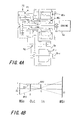
- Fig. 4A is a schematic construction diagram of the fourth embodiment of the present invention and Fig. 4B is its alignment chart.
- Fig. 5A is a schematic construction diagram of the fifth embodiment of the present invention and Fig. 5B is its alignment chart.
- Fig. 6A is a schematic construction diagram of the sixth embodiment of the present invention and Fig. 6B is its alignment chart.
- Fig. 7A is a schematic construction diagram of the seventh embodiment of the present invention and Fig. 7B is its alignment chart.
- Fig. 8A is a schematic construction diagram of the eighth embodiment of the present invention and Fig. 8B is its alignment chart.
- Fig. 9A is a schematic construction diagram of the ninth embodiment of the present invention and Fig. 9B is its alignment chart.
- Fig. 10A is a schematic construction diagram of the tenth embodiment of the present invention and Fig. 10B is its alignment chart.
- Fig. 11A is a schematic construction diagram of the eleventh embodiment of the present invention and Fig. 11B is its alignment chart.
- Fig. 12A is a schematic construction diagram of the twelfth embodiment of the present invention and Fig. 12B is its alignment chart.
- Fig. 13A is a schematic construction diagram of the thirteenth embodiment of the present invention and Fig. 13B is its alignment chart.
- Fig. 14A is a schematic construction diagram of the fourteenth embodiment of the present invention and Fig. 14B is its alignment chart.
- Fig. 15A is a schematic construction diagram of the fifteenth embodiment of the present invention and Fig. 15B is its alignment chart.
- Fig. 16A is a schematic construction diagram of the sixteenth embodiment of the present invention and Fig. 16B is its alignment chart.
- Fig. 17A is a schematic construction diagram of the seventeenth embodiment of the present invention and Fig. 17B is its alignment chart.
- Fig. 18A is a schematic construction diagram of the eighteenth embodiment of the present invention and Fig. 18B is its alignment chart.
- Fig. 19A is a schematic construction diagram of the nineteenth embodiment of the present invention and Fig. 19B is its alignment chart.
- Fig. 20A is a schematic construction diagram of the twentieth embodiment of the present invention and Fig. 20B is its alignment chart.
- Fig. 21A is a schematic construction diagram of the twenty-first embodiment of the present invention and Fig. 21B is its alignment chart.
- Fig. 22A is a schematic construction diagram of the twenty-second embodiment of the present invention and Fig. 22B is its alignment chart.
- Fig. 23A is a schematic construction diagram of the twenty-third embodiment of the present invention and Fig. 23B is its alignment chart.
- Fig. 24A is a schematic construction diagram of the twenty-fourth embodiment of the present invention and Fig. 24B is its alignment chart.
- Fig. 25A is a schematic construction diagram of the twenty-fifth embodiment of the present invention and Fig. 25B is its alignment chart.
- Figs. 26A-26D are explanatory diagrams for explaining the concept of the present invention.
- Fig. 27 is a characteristic diagram illustrating the relation between the output sharing ratio of motor-generators and the speed ratio.
- Fig. 28 is a characteristic diagram illustrating the relation between the output sharing ratio of the motor-generators and the vehicle speed.
- FIG. 1A and 1B show the schematic constructions and their alignment charts of different embodiments. Firstly, the embodiment of Figs 1A and 1B will be described in detail with respect to its construction, and the remaining embodiments will be described only with respect to points of difference. The common members among these embodiments will be designated by common reference numerals.
- reference letters Hm designate a motor housing, Ct a transmission casing, Hc a clutch housing, and Ha an axle housing.
- the clutch housing Hc is provided with a clutch CL for coupling or decoupling an output shaft Je of an engine Eg and a transmission input shaft Jr1.
- a single-pinion planetary gear train P1 and a double-pinion planetary gear train P2 are connected to share their ring gears R and carriers C (composite planetary gear mechanism) and are housed in the casing Ct.
- the input shaft Jr1, to which the clutch CL is connected, is the ring gear shaft of the planetary gear train P1.
- the input shaft Jr1 is equipped with a one-way clutch CLo for preventing the reverse rotation of the engine Eg.
- the suffix numeral 1 designates the components of the first planetary gear train P1
- the suffix numeral 2 designates the components of the second planetary gear train P2.
- the planetary gear train P2 of the double pinion type is expressed (as in the following construction diagrams) in diagrams expanded conveniently in a section extending through the two pinion shafts.
- an inner rotor Rmi and an annular outer rotor Rmo by which compact electric machines are constructed to act as two motor-generators MGi and MGo.
- an annular coil Cm by which the rotors Rmi and Rmo can be respectively actuated as a generator or motor.
- An inner rotor shaft Jmi is connected to a sun gear S1 of the planetary gear train P1 through a hollow outer rotor shaft Jmo, and the outer rotor shaft Jmo is connected to a sun gear S2 of the planetary gear train P2.
- 1A designate rotation speed sensors for detecting the rotation speeds of the inner rotor shaft Jmi and the outer rotor shaft Jmo respectively.
- the suffix letter i designates the components of the first motor-generator MGi
- the suffix letter o designates the components of the second motor-generator MGo.
- the axle housing Ha is connected to the side face of the transmission casing Ct.
- a final reduction mechanism Fin and a drive shaft Drv are supported in parallel with the planetary gear trains P1 and P2.
- the rotation of the carrier C is transmitted to the final reduction mechanism Fin through a reduction gear Rg.
- a carrier shaft Jc is an output shaft connected to the drive shaft Drv via the final reduction mechanism Fin.
- a ring gear R3 which is supported coaxially with the ring gear R of the planetary gear train P1 meshes with inner pinions pi meshing with the sun gear S2 and outer pinions po of the planetary gear train P2.
- a brake B for braking the rotation of the ring gear R3 is mounted in the casing Ct.
- reference letters EV designate characteristics while running only by the motor-generators MGi and MGo, START characteristics at the starting time with the brake B being applied, MAX characteristics at the maximum vehicle speed, and REV characteristics while reverse running.
- reference letters Out designate the output to the drive shaft Drv, and letters In designate the input from the engine Eg.
- the vehicle can be driven only by the motor-generators MGi and MGo by decoupling the engine Eg under the condition in which the engine Eg is frictional.
- the drivetrain can be downsized in order to improve its weight and mountability on the vehicle.
- the ratio of the output rotation speed relative to the input rotation speed increases when the brake B is applied as illustrated in Fig. 1B, i.e., a large speed ratio can be obtained, the large torque can be generated, to improve the driving force and the starting performance from a stationary state.
- Figs. 1A The differences from the construction of Figs. 1A reside in that the clutch CL and the brake B are omitted, in that the planetary gear train P1 having the sun gear S1 connected to the inner rotor shaft Jmi is a double-pinion type whereas the planetary gear train P2 having the sun gear S2 connected to the outer rotor shaft Jmo is a single-pinion type, in that the carrier shaft Jc is the input shaft connected to the engine Eg, and in that the ring gear R is connected to the final reduction mechanism Fin through the reduction gear Rg.
- letters Fw in Fig. 2A designate a flywheel of the engine Eg.
- Fig. 1A The differences from the construction of Fig. 1A reside in that the clutch CL and the brake B are omitted, and in that the motor-generators MGi and MGo which have a large weight and rotate at high speed are arranged between the engine Eg and the planetary gear trains P1 and P2 to reduce vibrations from the motor-generators MGi and MGo.
- the rotor shaft Jmo of the motor-generator MGo is folded back on the engine side and is connected to the sun gear S2 of the planetary gear train P2 through the hollow inner rotor shaft Jmi.
- the coupling portion between the ring gear R and the reduction gear Rg is disposed on the motor-generator side to reduce the size of the drivetrain more.
- the clutch CL is added to the construction of Fig. 2A.
- Fig. 1A The differences from the construction of Fig. 1A reside in that the brake B is omitted, and in that the carrier shaft Jc is the input shaft connected to the engine output shaft Je via the clutch CL whereas the ring gear shaft Jr is connected as the output shaft to the final reduction mechanism Fin via the reduction gear Rg.
- ring gear shaft Jr is the input shaft connected to the engine output shaft Je via the clutch CL whereas the carrier shaft Jc is the output shaft connected to the final reduction mechanism Fin via the reduction gear Rg.
- Fig. 7A The difference from the construction of Fig. 7A resides in that the planetary gear train P1 is a single-pinion type whereas the planetary gear train P2 is a double-pinion type.
- Fig. 8A The differences from the construction of Fig. 8A reside in that the planetary gear trains P1 and P2 are a single-pinion type, in that the carrier C1 of the planetary gear train P1 and the ring gear R2 of the planetary gear train P2 are connected whereas the ring gear R1 of the planetary gear train P1 and the carrier C2 of the planetary gear train P2 are connected, and in that the carrier shaft Jc1 of the planetary gear train P1 is the input shaft connected to the engine Eg whereas the carrier shaft Jc2 of the planetary gear train P2 is the output shaft connected to the final reduction mechanism Fin.
- Fig. 8A The differences from the construction of Fig. 8A reside in that the planetary gear trains P1 and P2 are a single-pinion type, and in that a common sun gear S is connected to the rotor shaft Jmi of the motor-generator MGi whereas the carrier shaft Jc of the common carrier C is the input shaft connected to the engine Eg. Moreover, the ring gear shaft Jr2 of the planetary gear train P2 is connected to the rotor shaft Jmo of the motor-generator MGo whereas the ring gear shaft Jr1 of the planetary gear train P1 is connected to the final reduction mechanism Fin via the reduction gear Rg.
- Fig. 10A The differences from the construction of Fig. 10A reside in that the ring gear shaft Jr1 of the planetary gear train P1 is connected to the engine Eg, and in that the common carrier shaft Jc of the planetary gear trains P1 and P2 is the output shaft connected to the final reduction mechanism Fin via the reduction gear Rg.
- Fig. 7A The differences from the construction of Fig. 7A reside in that the planetary gear trains P1 and P2 are a single-pinion type, and in that the common ring gear R is connected to the outer rotor shaft Jmo whereas the carrier shaft Jc of the common carrier C is connected to the final reduction mechanism Fin via the reduction gear Rg.
- the tooth number ratio between the pinion p1 and the sun gear S1 of the planetary gear train P1 and the tooth number ratio of the pinion p2 and the sun gear S2 of the planetary gear train P2 are made different, the pinions p1 and p2 rotate integrally, and the sun gear shaft Js1 of the planetary gear train P1 is the input shaft connected to the engine Eg via the clutch CL whereas the sun gear shaft Js2 of the planetary gear train P2 is connected to the inner rotor shaft Jmi.
- Fig. 2A The differences from the construction of Fig. 2A reside in that the ring gear R3 meshes with the inner pinions pi of the planetary gear train P1, and in that the brake B brakes the ring gear R3.
- Fig. 8A The differences from the construction of Fig. 8A reside in that the ring gear R3 meshes with the inner pinions pi of the planetary gear train P2, and in that the brake B brakes the ring gear R3.
- Fig. 14A The difference from the construction of Fig. 14A resides in that the sun gear shaft Js1 of the planetary gear train P1 is connected to the outer rotor shaft Jmo whereas the sun gear shaft Js2 of the P2 is connected to the inner rotor shaft Jmi.
- Fig. 13A The differences from the construction of Fig. 13A reside in that the inner pinions pi of the planetary gear train P1 is shaped to have a small diameter and a tooth face split across the sun gear S2, the ring gear R3 having no axial overlap with the outer pinions po meshes with the inner pinions pi, and in that the ring gear shaft Jr is the input shaft connected to the engine output shaft Je whereas the carrier shaft Jc is the output shaft connected to the final reduction mechanism Fin via the reduction gear Rg.
- ring gear shaft Jr is the input shaft connected to the engine output shaft Je via the clutch CL.
- ring gear shaft Jr is the input shaft connected to the engine output shaft Je via the clutch CL.
- Fig. 13A The difference from the construction of Fig. 13A resides in that the carrier shaft Jc is the input shaft connected to the engine output shaft Je via the clutch CL.
- Fig. 4A The differences from the construction of Fig. 4A reside in that the ring gear R3 meshes with the inner pinions pi of the planetary gear train P2, and in that the brake B brakes the ring gear R3.
- Fig. 5A The difference from the construction of Fig. 5A resides in that the construction is provided with the brake B for braking the inner rotor shaft Jmi.
- Fig. 10A The differences from the construction of Fig. 10A reside in that the clutch CL is omitted and the construction is provided with the brake B for braking the ring gear R2 of the planetary gear train P2.
- Fig. 21A The difference from the construction of Fig. 21A resides in that the carrier shaft Jc is the input shaft connected to the engine output shaft Je via the clutch CL.
- Fig. 22A The difference from the construction of Fig. 22A resides in that the carrier shaft Jc is the input shaft connected to the engine output shaft Je via the clutch CL.
- Fig. 3A The difference from the construction of Fig. 3A resides in that the construction is provided with the brake B for braking the carrier shaft Jc which is the input shaft.
- the drivetrain including the differential mechanism having four or more input/output elements arrayed on the alignment chart.
- the input from the engine is assigned to one of two elements of the elements arrayed on the inner side whereas the output to output shaft is assigned to the other, the motor-generators are connected to the two elements arrayed on the two outer sides of the inner elements.
- the differential mechanism is constructed of the planetary gear mechanism.
- the planetary gear mechanism includes the single-pinion type first planetary gear train and the double-pinion type second planetary gear train, any two elements -of the sun gears, carriers and ring gears are shared to construct the two-freedom-degree, four-element differential mechanism.
- the two motor-generators of the first invention are constructed by inner and outer rotors arranged coaxially.
- the inner one of the two rotors of the fifth invention is rotated at a higher speed than the outer one.
- the motor-generators of the fifth invention having the inner and outer rotors are arranged between the planetary gear mechanism and the engine, and the outer rotor shaft of the motor-generators is folded back on the engine side and is connected to one element of the planetary gear mechanism through the hollow inner rotor shaft.
- the differential mechanism of the second invention is connected through the reduction gear to the drive shaft arranged in parallel with the planetary gear mechanism, to construct the drivetrain of the front-wheel drive vehicle.
- the rotation transmission mechanism is disposed in the coupling portion of the element of the differential mechanism of the first invention.
- the reverse rotation preventing mechanism is connected to the engine of the first invention.
- the motor-generator is connected to the element which is positioned on the outer side of the element connected to the engine or the output shaft on the alignment chart of the differential mechanism having four or more elements.
- the ratio, as shared by the motor-generator, of the energy to be transmitted from the engine to the output shaft can be reduced.
- the size of the motor-generator is reduced accordingly and the transmission efficiency of the drivetrain is enhanced. This point will be described in detail with reference to the alignment chart, as follows.
- Figs. 26A-26D present a construction and alignment charts of the differential mechanism of four elements.
- the differential mechanism can be realized by various mechanisms, here will be representatively described the differential mechanism which is constructed, as shown, by combining a single-pinion type first planetary gear train P1 and a double-pinion type second planetary gear train P2.
- reference letter S designates the sun gear
- C the planetary carrier (as will be shortly called the "carrier")
- R the ring gear
- the suffix numeral 1 designates the components of the first planetary gear train P1
- the suffix numeral 2 designates the components of the second planetary gear train P2.
- the second planetary gear train P2 is conveniently illustrated on its structure in diagrams exploded in a section extending through two pinion shafts.
- Figs. 26B and 26C illustrate the relations of Formulas (1) and (2) respectively. If the tooth number is distributed on an abscissa and if the rotation speed of each element is expressed on an ordinate at a point distributed at a tooth number ratio, the rotation speeds of the elements always take linear relations proportional to the tooth ratio. In this planetary gear train of the three elements, where the motor-generator, the engine, the motor-generator for driving the drive shaft are connected to the each elements, the energy supported by the motor-generators increases and has an adverse effect on transmission efficiency, because of the limitation on the relationship between the speed ratio between the engine and the output shaft and the rotation speeds of the two motor-generators.
- the elements to be connected to the input/output sides are four: the sun gear S1 of the first planetary gear train P1, the sun gear S2 of the second planetary gear train P2, and the carrier C (C1 and C2) and the ring gear R (R1 and R2) shared between the planetary gear trains.
- An alignment chart of this case is shown in Fig. 26D.
- This composite planetary gear mechanism is known as a Ravineaux planetary gear train. This composite planetary gear mechanism has four elements and two degrees of freedom. That is, if the rotation speeds of any two elements are determined, the rotation speeds of the remaining two elements are determined.
- an input In from the engine and an output Out to the output shaft are assigned to the two elements on the inner side in the alignment chart of Fig. 26D, and motor-generators MGi and MGo are individually connected to the two elements on the outer sides. Therefore, the torque supported by the motor-generator with respect to the engine output, that is, the energy passing through the motor-generators can be lower and consequently improves the transmission efficiency of drivetrain.
- Fig. 27 illustrates relations between the speed ratio between the engine and the output shaft and the ratio of the output (as will be called the "output sharing ratio") passing through the motor-generators MGi and MGo to the engine output under the balanced condition of the input/output between the motor-generators MGi and MGo.
- the output sharing ratio of the motor-generators MGi and MGo is suppressed within about 30% of the output generated by the engine.
- Fig. 28 illustrates relations between the output sharing ratio of the motor generators and the vehicle speed of the case where the aforementioned construction is applied to the hybrid vehicle.
- the "PRESENT INVENTION (1)” and the “PRESENT INVENTION (2)” in Fig. 28 are different from each other only in the settings of the final reduction ratio of the vehicle, and the drive can be made in most vehicle speed ranges in either case at the output sharing ratio of 30 % or less of the motor-generators.
- the output share of the motor-generators can be decreased by setting the motor-generators at as a high rotation speed as possible (i.e., by enlarging the length between the motor-generators and the input/output on the alignment chart), and the efficiency can be enhanced by rotating the motor-generator closer to the element connected to the output shaft, at a high speed.
- the two motor-generators can be downsized by arranging the inner and outer rotors coaxially, and the output share of the motor-generator can be optimized by setting the inner rotor to rotate at a higher speed.
- the motor-generators having the inner and outer rotors are arranged between the planetary gear mechanism and the engine, and the outer rotor shaft of the motor-generator is folded back on the engine side and is connected to one element of the planetary gear mechanism through a hollow inner rotor shaft. With this construction, therefore, the motor-generators can be arranged at a position closer to the engine thereby to decrease vibrations.
- the engine, the motor-generators and the planetary gear mechanism can be coaxially arranged.
- the drive shaft arranged in parallel with the planetary gear mechanism can be connected through the reduction mechanism to construct a compact drivetrain suitable
- Each elements of the planetary gear mechanism composing the differential mechanism according to the present invention can be constructed such that the engine or the output shaft is connected to them either directly or through a rotation transmitting mechanism such as a reduction gear or clutch.
- the reverse torque may be inputted to the engine in a certain running state of the two motor-generators. It is, therefore, desirable that the engine is provided with a reverse rotation preventing mechanism such as a one-way clutch.
Abstract
Description
- The present invention relates to a drivetrain for a hybrid vehicle including an engine and a motor and, more particularly, to a drivetrain which performs a continuously variable speed change by a differential mechanism such as a planetary gear mechanism.
- JP2000-142146A published by the Japanese Patent Office in 2000 discloses a drivetrain for a hybrid vehicle which is constructed by connecting a generator, an engine and a motor for driving a vehicle to a sun gear, a planetary carrier and a ring gear of a planetary gear mechanism. According to this drivetrain, the continuously variable speed change and the increase or decrease of the output torque can be performed by using the differential function of the gears to distribute the engine output partially to the generator and supplying the generated electric power to the motor.
- In the above drivetrain using the three-component planetary gear mechanism, a large generator and a motor are required since it is difficult to increase the energy passing through the planetary gears due to mechanical restrictions. If the energy passing through the generator and the motor is high, the transmission efficiency of the drivetrain decreases.
- The electric energy generated by the generator is supplied through a converter and an inverter to the motor so that it is converted into mechanical energy. The energy transmission realized by the conversion between the electric energy and the mechanical energy displays considerably lower efficiency than a mechanical transmission by the gears or the like. In other words, the drivetrain displays lower transmission efficiency as the ratio of the energy passing through the generator and the motor increases.
- It is therefore an object of this invention to improve the transmission efficiency of the drivetrain by distributing the motive power by a differential mechanism having at least four elements and to increase the energy mechanically transmitted from an engine to a drive shaft.
- In order to achieve above object, this invention provides a drivetrain for transmitting driving force from an engine to a drive shaft of a vehicle, comprising a composite planetary gear mechanism including first to fourth rotational elements arrayed on an alignment chart, the first rotational element being connected to an output shaft of the engine and the second rotational element being connected to the drive shaft, a first motor-generator connected to the third rotational element, and a second motor-generator connected to the fourth rotational element, the second motor-generator being arranged coaxially with the first motor-generator.
- The details as well as other features and advantages of this invention are set forth in the remainder of the specification and are shown in the accompanying drawings.
- Fig. 1A is a schematic construction diagram of a first embodiment of the present invention and Fig. 1B is its alignment chart.
- Fig. 2A is a schematic construction diagram of the second embodiment of the present invention and Fig. 2B is its alignment chart.
- Fig. 3A is a schematic construction diagram of the third embodiment of the present invention and Fig. 3B is its alignment chart.
- Fig. 4A is a schematic construction diagram of the fourth embodiment of the present invention and Fig. 4B is its alignment chart.
- Fig. 5A is a schematic construction diagram of the fifth embodiment of the present invention and Fig. 5B is its alignment chart.
- Fig. 6A is a schematic construction diagram of the sixth embodiment of the present invention and Fig. 6B is its alignment chart.
- Fig. 7A is a schematic construction diagram of the seventh embodiment of the present invention and Fig. 7B is its alignment chart.
- Fig. 8A is a schematic construction diagram of the eighth embodiment of the present invention and Fig. 8B is its alignment chart.
- Fig. 9A is a schematic construction diagram of the ninth embodiment of the present invention and Fig. 9B is its alignment chart.
- Fig. 10A is a schematic construction diagram of the tenth embodiment of the present invention and Fig. 10B is its alignment chart.
- Fig. 11A is a schematic construction diagram of the eleventh embodiment of the present invention and Fig. 11B is its alignment chart.
- Fig. 12A is a schematic construction diagram of the twelfth embodiment of the present invention and Fig. 12B is its alignment chart.
- Fig. 13A is a schematic construction diagram of the thirteenth embodiment of the present invention and Fig. 13B is its alignment chart.
- Fig. 14A is a schematic construction diagram of the fourteenth embodiment of the present invention and Fig. 14B is its alignment chart.
- Fig. 15A is a schematic construction diagram of the fifteenth embodiment of the present invention and Fig. 15B is its alignment chart.
- Fig. 16A is a schematic construction diagram of the sixteenth embodiment of the present invention and Fig. 16B is its alignment chart.
- Fig. 17A is a schematic construction diagram of the seventeenth embodiment of the present invention and Fig. 17B is its alignment chart.
- Fig. 18A is a schematic construction diagram of the eighteenth embodiment of the present invention and Fig. 18B is its alignment chart.
- Fig. 19A is a schematic construction diagram of the nineteenth embodiment of the present invention and Fig. 19B is its alignment chart.
- Fig. 20A is a schematic construction diagram of the twentieth embodiment of the present invention and Fig. 20B is its alignment chart.
- Fig. 21A is a schematic construction diagram of the twenty-first embodiment of the present invention and Fig. 21B is its alignment chart.
- Fig. 22A is a schematic construction diagram of the twenty-second embodiment of the present invention and Fig. 22B is its alignment chart.
- Fig. 23A is a schematic construction diagram of the twenty-third embodiment of the present invention and Fig. 23B is its alignment chart.
- Fig. 24A is a schematic construction diagram of the twenty-fourth embodiment of the present invention and Fig. 24B is its alignment chart.
- Fig. 25A is a schematic construction diagram of the twenty-fifth embodiment of the present invention and Fig. 25B is its alignment chart.
- Figs. 26A-26D are explanatory diagrams for explaining the concept of the present invention.
- Fig. 27 is a characteristic diagram illustrating the relation between the output sharing ratio of motor-generators and the speed ratio.
- Fig. 28 is a characteristic diagram illustrating the relation between the output sharing ratio of the motor-generators and the vehicle speed.
- With reference to the accompanying drawings, embodiments in which the present invention is applied to a drivetrain for a front-wheel drive vehicle will be described. Figs. 1A and 1B and succeeding figures show the schematic constructions and their alignment charts of different embodiments. Firstly, the embodiment of Figs 1A and 1B will be described in detail with respect to its construction, and the remaining embodiments will be described only with respect to points of difference. The common members among these embodiments will be designated by common reference numerals.
- In Figs. 1A and 1B, reference letters Hm designate a motor housing, Ct a transmission casing, Hc a clutch housing, and Ha an axle housing. The clutch housing Hc is provided with a clutch CL for coupling or decoupling an output shaft Je of an engine Eg and a transmission input shaft Jr1. A single-pinion planetary gear train P1 and a double-pinion planetary gear train P2 are connected to share their ring gears R and carriers C (composite planetary gear mechanism) and are housed in the casing Ct. The input shaft Jr1, to which the clutch CL is connected, is the ring gear shaft of the planetary gear train P1. The input shaft Jr1 is equipped with a one-way clutch CLo for preventing the reverse rotation of the engine Eg. Here, in the reference numerals designating the components of the planetary gear trains P1 and P2, the
suffix numeral 1 designates the components of the first planetary gear train P1, and thesuffix numeral 2 designates the components of the second planetary gear train P2. Moreover, the planetary gear train P2 of the double pinion type is expressed (as in the following construction diagrams) in diagrams expanded conveniently in a section extending through the two pinion shafts. - In the motor housing Hm, there are coaxially supported an inner rotor Rmi and an annular outer rotor Rmo, by which compact electric machines are constructed to act as two motor-generators MGi and MGo. Between the inner and outer rotors Rmi and Rmo, there is interposed an annular coil Cm, by which the rotors Rmi and Rmo can be respectively actuated as a generator or motor. An inner rotor shaft Jmi is connected to a sun gear S1 of the planetary gear train P1 through a hollow outer rotor shaft Jmo, and the outer rotor shaft Jmo is connected to a sun gear S2 of the planetary gear train P2. Letters Ssi and Sso in Fig. 1A designate rotation speed sensors for detecting the rotation speeds of the inner rotor shaft Jmi and the outer rotor shaft Jmo respectively. Here, in the reference numerals designating the components of the motor-generators MGi and MGo, the suffix letter i designates the components of the first motor-generator MGi, and the suffix letter o designates the components of the second motor-generator MGo.
- The axle housing Ha is connected to the side face of the transmission casing Ct. In the axle housing Ha, a final reduction mechanism Fin and a drive shaft Drv are supported in parallel with the planetary gear trains P1 and P2. The rotation of the carrier C is transmitted to the final reduction mechanism Fin through a reduction gear Rg. In this case, a carrier shaft Jc is an output shaft connected to the drive shaft Drv via the final reduction mechanism Fin.
- A ring gear R3 which is supported coaxially with the ring gear R of the planetary gear train P1 meshes with inner pinions pi meshing with the sun gear S2 and outer pinions po of the planetary gear train P2. A brake B for braking the rotation of the ring gear R3 is mounted in the casing Ct.
- In the alignment chart of Fig 1B, reference letters EV designate characteristics while running only by the motor-generators MGi and MGo, START characteristics at the starting time with the brake B being applied, MAX characteristics at the maximum vehicle speed, and REV characteristics while reverse running. Moreover, reference letters Out designate the output to the drive shaft Drv, and letters In designate the input from the engine Eg.
- In this embodiment, by providing the clutch CL, the vehicle can be driven only by the motor-generators MGi and MGo by decoupling the engine Eg under the condition in which the engine Eg is frictional.
- Moreover, since these two motor-generators MGi and MGo are coaxially arranged to enable more compact construction, the drivetrain can be downsized in order to improve its weight and mountability on the vehicle.
- Further, since the ratio of the output rotation speed relative to the input rotation speed increases when the brake B is applied as illustrated in Fig. 1B, i.e., a large speed ratio can be obtained, the large torque can be generated, to improve the driving force and the starting performance from a stationary state.
- The differences from the construction of Figs. 1A reside in that the clutch CL and the brake B are omitted, in that the planetary gear train P1 having the sun gear S1 connected to the inner rotor shaft Jmi is a double-pinion type whereas the planetary gear train P2 having the sun gear S2 connected to the outer rotor shaft Jmo is a single-pinion type, in that the carrier shaft Jc is the input shaft connected to the engine Eg, and in that the ring gear R is connected to the final reduction mechanism Fin through the reduction gear Rg. Here, letters Fw in Fig. 2A designate a flywheel of the engine Eg.
- The differences from the construction of Fig. 1A reside in that the clutch CL and the brake B are omitted, and in that the motor-generators MGi and MGo which have a large weight and rotate at high speed are arranged between the engine Eg and the planetary gear trains P1 and P2 to reduce vibrations from the motor-generators MGi and MGo. The rotor shaft Jmo of the motor-generator MGo is folded back on the engine side and is connected to the sun gear S2 of the planetary gear train P2 through the hollow inner rotor shaft Jmi.
- Contrary to the Embodiment as shown in Fig. 3A, the coupling portion between the ring gear R and the reduction gear Rg is disposed on the motor-generator side to reduce the size of the drivetrain more.
- The clutch CL is added to the construction of Fig. 2A.
- The differences from the construction of Fig. 1A reside in that the brake B is omitted, and in that the carrier shaft Jc is the input shaft connected to the engine output shaft Je via the clutch CL whereas the ring gear shaft Jr is connected as the output shaft to the final reduction mechanism Fin via the reduction gear Rg.
- The difference from the construction of Fig. 2A resides in that the ring gear shaft Jr is the input shaft connected to the engine output shaft Je via the clutch CL whereas the carrier shaft Jc is the output shaft connected to the final reduction mechanism Fin via the reduction gear Rg.
- The difference from the construction of Fig. 7A resides in that the planetary gear train P1 is a single-pinion type whereas the planetary gear train P2 is a double-pinion type.
- The differences from the construction of Fig. 8A reside in that the planetary gear trains P1 and P2 are a single-pinion type, in that the carrier C1 of the planetary gear train P1 and the ring gear R2 of the planetary gear train P2 are connected whereas the ring gear R1 of the planetary gear train P1 and the carrier C2 of the planetary gear train P2 are connected, and in that the carrier shaft Jc1 of the planetary gear train P1 is the input shaft connected to the engine Eg whereas the carrier shaft Jc2 of the planetary gear train P2 is the output shaft connected to the final reduction mechanism Fin.
- The differences from the construction of Fig. 8A reside in that the planetary gear trains P1 and P2 are a single-pinion type, and in that a common sun gear S is connected to the rotor shaft Jmi of the motor-generator MGi whereas the carrier shaft Jc of the common carrier C is the input shaft connected to the engine Eg. Moreover, the ring gear shaft Jr2 of the planetary gear train P2 is connected to the rotor shaft Jmo of the motor-generator MGo whereas the ring gear shaft Jr1 of the planetary gear train P1 is connected to the final reduction mechanism Fin via the reduction gear Rg.
- The differences from the construction of Fig. 10A reside in that the ring gear shaft Jr1 of the planetary gear train P1 is connected to the engine Eg, and in that the common carrier shaft Jc of the planetary gear trains P1 and P2 is the output shaft connected to the final reduction mechanism Fin via the reduction gear Rg.
- The differences from the construction of Fig. 7A reside in that the planetary gear trains P1 and P2 are a single-pinion type, and in that the common ring gear R is connected to the outer rotor shaft Jmo whereas the carrier shaft Jc of the common carrier C is connected to the final reduction mechanism Fin via the reduction gear Rg. Moreover, the tooth number ratio between the pinion p1 and the sun gear S1 of the planetary gear train P1 and the tooth number ratio of the pinion p2 and the sun gear S2 of the planetary gear train P2 are made different, the pinions p1 and p2 rotate integrally, and the sun gear shaft Js1 of the planetary gear train P1 is the input shaft connected to the engine Eg via the clutch CL whereas the sun gear shaft Js2 of the planetary gear train P2 is connected to the inner rotor shaft Jmi.
- The differences from the construction of Fig. 2A reside in that the ring gear R3 meshes with the inner pinions pi of the planetary gear train P1, and in that the brake B brakes the ring gear R3.
- The differences from the construction of Fig. 8A reside in that the ring gear R3 meshes with the inner pinions pi of the planetary gear train P2, and in that the brake B brakes the ring gear R3.
- The difference from the construction of Fig. 14A resides in that the sun gear shaft Js1 of the planetary gear train P1 is connected to the outer rotor shaft Jmo whereas the sun gear shaft Js2 of the P2 is connected to the inner rotor shaft Jmi.
- The differences from the construction of Fig. 13A reside in that the inner pinions pi of the planetary gear train P1 is shaped to have a small diameter and a tooth face split across the sun gear S2, the ring gear R3 having no axial overlap with the outer pinions po meshes with the inner pinions pi, and in that the ring gear shaft Jr is the input shaft connected to the engine output shaft Je whereas the carrier shaft Jc is the output shaft connected to the final reduction mechanism Fin via the reduction gear Rg.
- The difference from the construction of Fig. 15A resides in that the ring gear shaft Jr is the input shaft connected to the engine output shaft Je via the clutch CL.
- The difference from the construction of Fig. 16A resides in that the ring gear shaft Jr is the input shaft connected to the engine output shaft Je via the clutch CL.
- The difference from the construction of Fig. 13A resides in that the carrier shaft Jc is the input shaft connected to the engine output shaft Je via the clutch CL.
- The differences from the construction of Fig. 4A reside in that the ring gear R3 meshes with the inner pinions pi of the planetary gear train P2, and in that the brake B brakes the ring gear R3.
- The difference from the construction of Fig. 5A resides in that the construction is provided with the brake B for braking the inner rotor shaft Jmi.
- The differences from the construction of Fig. 10A reside in that the clutch CL is omitted and the construction is provided with the brake B for braking the ring gear R2 of the planetary gear train P2.
- The difference from the construction of Fig. 21A resides in that the carrier shaft Jc is the input shaft connected to the engine output shaft Je via the clutch CL.
- The difference from the construction of Fig. 22A resides in that the carrier shaft Jc is the input shaft connected to the engine output shaft Je via the clutch CL.
- The difference from the construction of Fig. 3A resides in that the construction is provided with the brake B for braking the carrier shaft Jc which is the input shaft.
- The inventions supported by the above-mentioned embodiments are as follows:
- In the first invention, there is provided the drivetrain including the differential mechanism having four or more input/output elements arrayed on the alignment chart. The input from the engine is assigned to one of two elements of the elements arrayed on the inner side whereas the output to output shaft is assigned to the other, the motor-generators are connected to the two elements arrayed on the two outer sides of the inner elements.
- In the second invention, the differential mechanism is constructed of the planetary gear mechanism.
- In the third invention, the planetary gear mechanism includes the single-pinion type first planetary gear train and the double-pinion type second planetary gear train, any two elements -of the sun gears, carriers and ring gears are shared to construct the two-freedom-degree, four-element differential mechanism.
- In the fourth invention, of the two motor-generators of the first invention, one connected to the element closer to the element assigned to the output shaft is rotated at a higher speed than the other motor-generator.
- In the fifth invention, the two motor-generators of the first invention are constructed by inner and outer rotors arranged coaxially.
- In the sixth invention, the inner one of the two rotors of the fifth invention is rotated at a higher speed than the outer one.
- In the seventh invention, the motor-generators of the fifth invention having the inner and outer rotors are arranged between the planetary gear mechanism and the engine, and the outer rotor shaft of the motor-generators is folded back on the engine side and is connected to one element of the planetary gear mechanism through the hollow inner rotor shaft.
- In the eighth invention, the differential mechanism of the second invention is connected through the reduction gear to the drive shaft arranged in parallel with the planetary gear mechanism, to construct the drivetrain of the front-wheel drive vehicle.
- In the ninth invention, the rotation transmission mechanism is disposed in the coupling portion of the element of the differential mechanism of the first invention.
- In the tenth invention, the reverse rotation preventing mechanism is connected to the engine of the first invention.
- According to the first and subsequent inventions, the motor-generator is connected to the element which is positioned on the outer side of the element connected to the engine or the output shaft on the alignment chart of the differential mechanism having four or more elements. The ratio, as shared by the motor-generator, of the energy to be transmitted from the engine to the output shaft can be reduced. The size of the motor-generator is reduced accordingly and the transmission efficiency of the drivetrain is enhanced. This point will be described in detail with reference to the alignment chart, as follows.
- Figs. 26A-26D present a construction and alignment charts of the differential mechanism of four elements. Although the differential mechanism can be realized by various mechanisms, here will be representatively described the differential mechanism which is constructed, as shown, by combining a single-pinion type first planetary gear train P1 and a double-pinion type second planetary gear train P2.
- In Fig. 26A, reference letter S designates the sun gear, C the planetary carrier (as will be shortly called the "carrier"), and R the ring gear. The
suffix numeral 1 designates the components of the first planetary gear train P1, and thesuffix numeral 2 designates the components of the second planetary gear train P2. Here, the second planetary gear train P2 is conveniently illustrated on its structure in diagrams exploded in a section extending through two pinion shafts. - Now, if the sun gear and the ring gear have respective tooth numbers of Za and Zr and if the sun gear, the carrier and the ring gear have respective rotation speeds of Na, Nc and Nr, the individual rotation speeds are expressed in the following relations (1) for the first planetary gear train P1 and (2) for the second planetary gear train P2:


- Figs. 26B and 26C illustrate the relations of Formulas (1) and (2) respectively. If the tooth number is distributed on an abscissa and if the rotation speed of each element is expressed on an ordinate at a point distributed at a tooth number ratio, the rotation speeds of the elements always take linear relations proportional to the tooth ratio. In this planetary gear train of the three elements, where the motor-generator, the engine, the motor-generator for driving the drive shaft are connected to the each elements, the energy supported by the motor-generators increases and has an adverse effect on transmission efficiency, because of the limitation on the relationship between the speed ratio between the engine and the output shaft and the rotation speeds of the two motor-generators.
- On the other hand, if two sets of planetary gear trains are combined by sharing the ring gear R1 and the carrier C1 of the first planetary gear train P1 with the ring gear R2 and the carrier C2 of the second planetary gear train P2, as illustrated, the elements to be connected to the input/output sides are four: the sun gear S1 of the first planetary gear train P1, the sun gear S2 of the second planetary gear train P2, and the carrier C (C1 and C2) and the ring gear R (R1 and R2) shared between the planetary gear trains. An alignment chart of this case is shown in Fig. 26D. This composite planetary gear mechanism is known as a Ravineaux planetary gear train. This composite planetary gear mechanism has four elements and two degrees of freedom. That is, if the rotation speeds of any two elements are determined, the rotation speeds of the remaining two elements are determined.
- If the input from the engine and the output to the output shaft are assigned to any two of the four elements and if the motor-generators are connected to the remaining two elements, there are many combinations of the speeds of the two motor-generators which achieves a certain speed ratio between the input rotation speed and output rotation speed. From these combinations, therefore, there can be selected the combination which can minimize the power supported by the motor-generators.
- Especially in the present invention, an input In from the engine and an output Out to the output shaft are assigned to the two elements on the inner side in the alignment chart of Fig. 26D, and motor-generators MGi and MGo are individually connected to the two elements on the outer sides. Therefore, the torque supported by the motor-generator with respect to the engine output, that is, the energy passing through the motor-generators can be lower and consequently improves the transmission efficiency of drivetrain.
- Fig. 27 illustrates relations between the speed ratio between the engine and the output shaft and the ratio of the output (as will be called the "output sharing ratio") passing through the motor-generators MGi and MGo to the engine output under the balanced condition of the input/output between the motor-generators MGi and MGo. In the region of a speed ratio of 0.4 to 2.0 (or a reduction ratio of 2.5 to 0.5), as illustrated, the output sharing ratio of the motor-generators MGi and MGo is suppressed within about 30% of the output generated by the engine.
- Fig. 28 illustrates relations between the output sharing ratio of the motor generators and the vehicle speed of the case where the aforementioned construction is applied to the hybrid vehicle. The "PRESENT INVENTION (1)" and the "PRESENT INVENTION (2)" in Fig. 28 are different from each other only in the settings of the final reduction ratio of the vehicle, and the drive can be made in most vehicle speed ranges in either case at the output sharing ratio of 30 % or less of the motor-generators.
- From these figures, according to the present invention, it is found that motor-generators of a lower output can be applied and a higher transmission efficiency can be achieved than the related art where the present invention is not applied. The letters SHV in Fig. 28 designate the case of a series hybrid vehicle, which is always given an output sharing ratio of 1 because the engine output is wholly used for driving the generator.
- In the drivetrain according to the present invention, the output share of the motor-generators can be decreased by setting the motor-generators at as a high rotation speed as possible (i.e., by enlarging the length between the motor-generators and the input/output on the alignment chart), and the efficiency can be enhanced by rotating the motor-generator closer to the element connected to the output shaft, at a high speed.
- Moreover, the two motor-generators can be downsized by arranging the inner and outer rotors coaxially, and the output share of the motor-generator can be optimized by setting the inner rotor to rotate at a higher speed. Moreover, the motor-generators having the inner and outer rotors are arranged between the planetary gear mechanism and the engine, and the outer rotor shaft of the motor-generator is folded back on the engine side and is connected to one element of the planetary gear mechanism through a hollow inner rotor shaft. With this construction, therefore, the motor-generators can be arranged at a position closer to the engine thereby to decrease vibrations.
- The engine, the motor-generators and the planetary gear mechanism can be coaxially arranged. The drive shaft arranged in parallel with the planetary gear mechanism can be connected through the reduction mechanism to construct a compact drivetrain suitable
- Each elements of the planetary gear mechanism composing the differential mechanism according to the present invention can be constructed such that the engine or the output shaft is connected to them either directly or through a rotation transmitting mechanism such as a reduction gear or clutch.
- Since the reverse torque may be inputted to the engine in a certain running state of the two motor-generators. It is, therefore, desirable that the engine is provided with a reverse rotation preventing mechanism such as a one-way clutch.
- The entire contents of Japanese Patent Application P2001-221222 (filed July 23, 2001) are incorporated herein by reference.
- Although the invention has been described above by reference to a certain embodiment of the invention, the invention is not limited to the embodiment described above. Modifications and variations of the embodiments described above will occur to those skilled in the art, in the light of the above teachings. The scope of the invention is defined with reference to the following claims.
Claims (10)
- A drivetrain for transmitting driving force from an engine (Eg) to a drive shaft (Drv) of a vehicle, comprising:a composite planetary gear mechanism (P1, P2) including first to fourth rotational elements arrayed on an alignment chart, the first rotational element being connected to an output shaft of the engine and the second rotational element being connected to the drive shaft,a first motor-generator (MGi) connected to the third rotational element, anda second motor-generator (MGo) connected to the fourth rotational element, the second motor-generator being arranged coaxially with the first motor-generator.
- A drivetrain according to claim 1, wherein:the first motor-generator (MGi) is constructed by a stator and a rotor arranged inside the stator, andthe second motor-generator (MGo) is constructed by the stator and a rotor arranged outside the stator.
- A drivetrain according to claim 2, wherein a rotation speed of the first motor-generator (MGi) is higher than a rotation speed of the second motor-generator (MGo).
- A drivetrain according to claim 2, wherein:the planetary gear mechanism (P1, P2) is arranged between the engine (Eg) and the two motor-generators (MGi, MGo), anda rotor shaft of the first motor-generator (MGi) is arranged through a hollow rotor shaft of the second motor-generator (MGo).
- A drivetrain according to claim 2, wherein:the planetary gear mechanism (P1, P2) is arranged between the engine (Eg) and the two motor-generators (MGi, MGo), anda rotor shaft of the second motor-generator (MGo) is arranged through a hollow rotor shaft of the first motor-generator (MGi).
- A drivetrain according to claim 2, wherein:the two motor-generators (MGi, MGo) are arranged between the engine (Eg) and the planetary gear mechanism (P1, P2), anda rotor shaft of the second motor-generator (MGo) is arranged through a hollow rotor shaft of the first motor-generator (MGi).
- A drivetrain according to claim 6, wherein:the rotor shaft of the second motor-generator (MGo) is hollow, andthe output shaft of the engine (Eg) is arranged through the hollow rotation shaft of the second motor-generator (MGo).
- A drivetrain according to claim 1, wherein:a distance on the alignment chart between the second rotational element and the third rotational element is shorter than a distance on the alignment chart between the second rotational element and the fourth rotational element, anda rotation speed of the first motor-generator (MGi) is higher than a rotation speed of the second motor-generator (MGo).
- A drivetrain according to claim 1, further comprising a clutch (CL) interposed between the output shaft of the engine (Eg) and the first rotational element.
- A drivetrain according to claim 1, further comprising a reverse rotation preventing mechanism (CLo) for preventing the first rotational element from rotating in reverse direction.
Applications Claiming Priority (2)
| Application Number | Priority Date | Filing Date | Title |
|---|---|---|---|
| JP2001221222A JP3578451B2 (en) | 2001-07-23 | 2001-07-23 | Drive |
| JP2001221222 | 2001-07-23 |
Publications (3)
| Publication Number | Publication Date |
|---|---|
| EP1279545A2 true EP1279545A2 (en) | 2003-01-29 |
| EP1279545A3 EP1279545A3 (en) | 2003-11-12 |
| EP1279545B1 EP1279545B1 (en) | 2010-04-28 |
Family
ID=19054920
Family Applications (1)
| Application Number | Title | Priority Date | Filing Date |
|---|---|---|---|
| EP02016510A Expired - Fee Related EP1279545B1 (en) | 2001-07-23 | 2002-07-23 | Hybrid drivetrain for a vehicle |
Country Status (4)
| Country | Link |
|---|---|
| US (1) | US6852053B2 (en) |
| EP (1) | EP1279545B1 (en) |
| JP (1) | JP3578451B2 (en) |
| DE (1) | DE60236125D1 (en) |
Cited By (18)
| Publication number | Priority date | Publication date | Assignee | Title |
|---|---|---|---|---|
| EP1375226A2 (en) | 2002-05-31 | 2004-01-02 | Nissan Motor Co., Ltd. | Hybridgetriebe |
| EP1375963A2 (en) * | 2002-06-17 | 2004-01-02 | Nissan Motor Co., Ltd. | Hybrid transmission |
| WO2004088168A1 (en) | 2003-03-29 | 2004-10-14 | Drivetec (Uk) Limited | Four branch differential transmission systems |
| WO2005101622A1 (en) * | 2004-04-15 | 2005-10-27 | Keiper Gmbh & Co. Kg | Drive unit of an adjusting device in a vehicle |
| WO2006032820A1 (en) * | 2004-09-24 | 2006-03-30 | Peugeot Citroen Automobiles Sa | Device for power transmission in a vehicle between a heat engine shaft and a wheel shaft |
| WO2006103501A3 (en) * | 2005-02-23 | 2006-11-23 | Toyota Motor Co Ltd | Power output device, control method for the same, and vehicle equipped therewith |
| EP1728666A1 (en) * | 2005-06-03 | 2006-12-06 | Nissan Motor Co., Ltd. | Vehicle drive control apparatus and method |
| EP1698504A3 (en) * | 2005-02-03 | 2006-12-06 | Nissan Motor Co., Ltd. | Hybrid vehicle and control method thereof |
| WO2007017719A2 (en) * | 2005-08-05 | 2007-02-15 | Bordini Engineering Srl | Hybrid traction system |
| US7294081B2 (en) | 2004-04-15 | 2007-11-13 | Keiper Gmbh & Co. Kg | Drive unit for a vehicle seat |
| US7329200B2 (en) | 2004-04-15 | 2008-02-12 | Keiper Gmbh & Co. Kg | Drive unit of an adjuster of a vehicle seat |
| US7345390B2 (en) | 2004-04-15 | 2008-03-18 | Keiper Gmbh & Co. Kg | Drive unit of an adjuster of a vehicle seat |
| US7544142B2 (en) | 2004-04-15 | 2009-06-09 | Keiper Gmbh & Co. Kg | Adjuster for a vehicle seat |
| AT513986A4 (en) * | 2013-03-15 | 2014-09-15 | Avl List Gmbh | Powertrain for a hybrid vehicle |
| JPWO2013140527A1 (en) * | 2012-03-19 | 2015-08-03 | トヨタ自動車株式会社 | Vehicle transmission |
| DE102004027139B4 (en) * | 2003-06-05 | 2015-09-10 | Toyota Jidosha Kabushiki Kaisha | Control system for hybrid vehicle |
| EP3234408B1 (en) * | 2014-12-19 | 2020-05-27 | Caleb Chung | Continuously variable transmission |
| US10774901B2 (en) | 2014-12-19 | 2020-09-15 | Caleb Chung | Continuously variable transmission |
Families Citing this family (58)
| Publication number | Priority date | Publication date | Assignee | Title |
|---|---|---|---|---|
| JP3641243B2 (en) * | 2002-02-26 | 2005-04-20 | 日産自動車株式会社 | Hybrid transmission |
| US7110867B2 (en) * | 2002-08-26 | 2006-09-19 | Nissan Motor Co., Ltd. | Vibration suppression apparatus and method for hybrid vehicle |
| US7001297B2 (en) * | 2002-11-14 | 2006-02-21 | Nissan Motor Co., Ltd. | Hybrid transmission |
| US6958027B2 (en) * | 2002-11-14 | 2005-10-25 | Nissan Motor Co., Ltd. | Hybrid transmission |
| US6932733B2 (en) * | 2002-11-22 | 2005-08-23 | Sauer-Danfoss Inc. | Hydromechanical transmission with differential steer |
| JP3626166B2 (en) * | 2003-01-17 | 2005-03-02 | 日産自動車株式会社 | Hybrid transmission |
| JP4543304B2 (en) * | 2003-05-06 | 2010-09-15 | アイシン・エィ・ダブリュ株式会社 | Split drive |
| JP3823949B2 (en) * | 2003-06-23 | 2006-09-20 | 日産自動車株式会社 | Hybrid vehicle mode transition control device |
| WO2005000620A1 (en) * | 2003-06-30 | 2005-01-06 | Toyota Jidosha Kabushiki Kaisha | Hybrid drive device and automobile with device mounted thereon |
| JP4088574B2 (en) * | 2003-09-05 | 2008-05-21 | トヨタ自動車株式会社 | Power output device and automobile equipped with the same |
| EP1524145A3 (en) | 2003-10-15 | 2006-01-04 | Nissan Motor Company, Limited | Drive train for hybrid vehicle |
| JP2005119573A (en) * | 2003-10-20 | 2005-05-12 | Toyota Motor Corp | Hybrid vehicle |
| JP3864950B2 (en) | 2003-11-18 | 2007-01-10 | 日産自動車株式会社 | Hybrid transmission |
| JP3858904B2 (en) * | 2004-03-11 | 2006-12-20 | 日産自動車株式会社 | Engagement method of engine clutch for hybrid transmission |
| JP4055725B2 (en) | 2004-03-17 | 2008-03-05 | 日産自動車株式会社 | Hybrid vehicle mode transition control device |
| JP4055726B2 (en) | 2004-03-17 | 2008-03-05 | 日産自動車株式会社 | Hybrid vehicle mode transition control device |
| JP4513387B2 (en) * | 2004-04-05 | 2010-07-28 | 日産自動車株式会社 | Hybrid vehicle generated power control device |
| JP4069901B2 (en) | 2004-05-20 | 2008-04-02 | トヨタ自動車株式会社 | Hybrid vehicle drivetrain |
| JP4026622B2 (en) * | 2004-07-06 | 2007-12-26 | 日産自動車株式会社 | Control device for hybrid vehicle |
| JP4239923B2 (en) * | 2004-08-02 | 2009-03-18 | 日産自動車株式会社 | Electric power transmission device |
| JP4059876B2 (en) * | 2004-10-14 | 2008-03-12 | トヨタ自動車株式会社 | Hybrid drive device |
| JP4179266B2 (en) * | 2004-11-08 | 2008-11-12 | 日産自動車株式会社 | Hybrid four-wheel drive system |
| US7588108B2 (en) * | 2005-03-16 | 2009-09-15 | Takayuki Miyao | Method of controlling vehicle driving system |
| EP1707905A1 (en) | 2005-03-16 | 2006-10-04 | Lg Electronics Inc. | Method for controlling operation of air conditioner |
| US7252612B2 (en) * | 2005-04-14 | 2007-08-07 | Gm Global Technology Operations, Inc. | Electrically variable transmission having two planetary gear sets with one fixed interconnection and a stationary member |
| US7220201B2 (en) * | 2005-04-22 | 2007-05-22 | Gm Global Technology Operations, Inc. | Electrically variable transmission having two planetary gear sets with two fixed interconnections and clutch input |
| JP4258496B2 (en) * | 2005-06-24 | 2009-04-30 | トヨタ自動車株式会社 | Vehicle drive device |
| JP4461078B2 (en) * | 2005-07-27 | 2010-05-12 | 三菱重工業株式会社 | Wind power generator |
| US7273435B2 (en) * | 2005-09-29 | 2007-09-25 | Gm Global Technology Operations, Inc. | Multi-mode electrically variable transmissions having two planetary gear sets with one fixed interconnection and clutched input |
| US7544141B2 (en) * | 2006-07-18 | 2009-06-09 | Gm Global Technology Operations, Inc. | Transmission device with selectable motor connections |
| US7712560B2 (en) * | 2006-09-06 | 2010-05-11 | Ford Global Technologies, Llc | Hybrid electric vehicle powertrain |
| US7704176B2 (en) * | 2007-01-31 | 2010-04-27 | Gm Global Technology Operations, Inc. | Electrically variable transmission device using multiple pairings of electrical machines |
| JP4505521B2 (en) * | 2008-07-09 | 2010-07-21 | 本田技研工業株式会社 | Power equipment |
| US8491431B2 (en) * | 2008-12-19 | 2013-07-23 | Caterpillar Inc. | Reconfigurable hybrid gear train |
| US7998016B2 (en) * | 2008-12-19 | 2011-08-16 | Caterpillar Inc. | Universal gear train |
| JP5268783B2 (en) * | 2009-05-29 | 2013-08-21 | 本田技研工業株式会社 | Power equipment |
| US8479851B2 (en) * | 2009-10-27 | 2013-07-09 | Magna Powertrain Of America, Inc. | Electric drive unit with modular motor assembly |
| US8517875B2 (en) * | 2009-11-12 | 2013-08-27 | Magna Powertrain, Inc. | Transmission having planetary gear drive with variable speed reduction |
| US8337352B2 (en) | 2010-06-22 | 2012-12-25 | Oshkosh Corporation | Electromechanical variable transmission |
| DE102011106530A1 (en) * | 2010-07-12 | 2012-01-12 | Schaeffler Technologies Gmbh & Co. Kg | Powertrain of a hybrid vehicle and hybrid vehicle |
| WO2012086036A1 (en) | 2010-12-22 | 2012-06-28 | トヨタ自動車株式会社 | Power transmitting device for vehicle |
| US8948950B2 (en) | 2011-02-21 | 2015-02-03 | Suzuki Motor Corporation | Drive control apparatus of hybrid vehicle |
| CN103380047B (en) | 2011-02-21 | 2016-04-06 | 铃木株式会社 | The driving control device of motor vehicle driven by mixed power |
| JP5824737B2 (en) | 2012-01-24 | 2015-11-25 | ジヤトコ株式会社 | Hybrid vehicle engine start control device |
| DE112013003825T5 (en) * | 2012-08-01 | 2015-04-30 | Honda Motor Co., Ltd. | drive system |
| US9132736B1 (en) | 2013-03-14 | 2015-09-15 | Oshkosh Defense, Llc | Methods, systems, and vehicles with electromechanical variable transmission |
| US9481256B2 (en) * | 2014-01-30 | 2016-11-01 | Amp Electric Vehicles Inc. | Onboard generator drive system for electric vehicles |
| CN103978882B (en) * | 2014-05-30 | 2016-08-17 | 长城汽车股份有限公司 | The power transmission of motor vehicle driven by mixed power |
| US11701959B2 (en) | 2015-02-17 | 2023-07-18 | Oshkosh Corporation | Inline electromechanical variable transmission system |
| US10982736B2 (en) | 2015-02-17 | 2021-04-20 | Oshkosh Corporation | Multi-mode electromechanical variable transmission |
| US10578195B2 (en) | 2015-02-17 | 2020-03-03 | Oshkosh Corporation | Inline electromechanical variable transmission system |
| US9651120B2 (en) | 2015-02-17 | 2017-05-16 | Oshkosh Corporation | Multi-mode electromechanical variable transmission |
| US9650032B2 (en) | 2015-02-17 | 2017-05-16 | Oshkosh Corporation | Multi-mode electromechanical variable transmission |
| US10584775B2 (en) | 2015-02-17 | 2020-03-10 | Oshkosh Corporation | Inline electromechanical variable transmission system |
| US10421350B2 (en) | 2015-10-20 | 2019-09-24 | Oshkosh Corporation | Inline electromechanical variable transmission system |
| US9656659B2 (en) | 2015-02-17 | 2017-05-23 | Oshkosh Corporation | Multi-mode electromechanical variable transmission |
| US9694663B2 (en) * | 2015-07-24 | 2017-07-04 | Ford Global Technologies, Llc | Hybrid transmission |
| DE102017204520A1 (en) | 2017-03-17 | 2018-09-20 | Magna powertrain gmbh & co kg | planetary gear |
Citations (2)
| Publication number | Priority date | Publication date | Assignee | Title |
|---|---|---|---|---|
| JP2000142146A (en) | 1998-11-04 | 2000-05-23 | Nissan Motor Co Ltd | Drive device for hybrid vehicle |
| JP2001221222A (en) | 2000-02-10 | 2001-08-17 | Skf Mekan Ab | Lock nut |
Family Cites Families (23)
| Publication number | Priority date | Publication date | Assignee | Title |
|---|---|---|---|---|
| US1515321A (en) | 1920-11-30 | 1924-11-11 | William A Neracher | Electromagnetic transmission mechanism |
| US3861484A (en) * | 1971-02-01 | 1975-01-21 | Kenneth E Joslin | Hybrid vehicular power system |
| JPH06323378A (en) * | 1993-05-11 | 1994-11-25 | Bridgestone Cycle Co | Transmission gear |
| US5558589A (en) | 1995-07-20 | 1996-09-24 | General Motors Corporation | Two-mode, compound-split, electro-mechanical vehicular transmission |
| GB9612231D0 (en) * | 1996-06-12 | 1996-08-14 | Harris Michael A | Variable transmission apparatus |
| JP3214368B2 (en) * | 1996-08-13 | 2001-10-02 | トヨタ自動車株式会社 | Power output device |
| CA2259771C (en) | 1998-02-19 | 2003-04-01 | Hitachi, Ltd. | Transmission, and vehicle and bicycle using the same |
| EP0945963B1 (en) | 1998-03-25 | 2003-11-05 | Nissan Motor Co., Ltd. | Motor/generator |
| JP3559891B2 (en) * | 1998-06-22 | 2004-09-02 | 日産自動車株式会社 | Cooling structure of multilayer motor |
| US5931757A (en) | 1998-06-24 | 1999-08-03 | General Motors Corporation | Two-mode, compound-split electro-mechanical vehicular transmission |
| US6022287A (en) | 1998-08-19 | 2000-02-08 | General Motors Corporation | Modularly constructed vehicular transmission |
| WO2000026053A1 (en) * | 1998-11-03 | 2000-05-11 | Robert Bosch Gmbh | Hybrid transmission, especially for motor vehicles |
| WO2000032433A1 (en) * | 1998-12-01 | 2000-06-08 | Hitachi, Ltd. | Drive device and vehicle |
| JP3412544B2 (en) * | 1999-02-04 | 2003-06-03 | トヨタ自動車株式会社 | Power output device and control method thereof |
| DE19909424A1 (en) | 1999-02-23 | 2000-08-24 | Peter Tenberge | Hybrid gearing for vehicle |
| FR2790615A1 (en) * | 1999-03-03 | 2000-09-08 | Patrick Boissiere | Rotating electrical machine such as generator or motor, comprises two rotors, concentrically mounted, in a fixed frame, and rotating in opposite senses |
| US6090005A (en) | 1999-07-26 | 2000-07-18 | General Motors Corporation | Two-mode, compound-split, vehicular transmission having both enhanced speed and enhanced tractive power |
| FR2799418B1 (en) | 1999-10-11 | 2001-12-14 | Renault | MOTOR-PROPELLER GROUP OF A HYBRID VEHICLE WITH ELECTROMAGNETIC COUPLER |
| US6563246B1 (en) * | 1999-10-14 | 2003-05-13 | Denso Corporation | Rotary electric machine for electric vehicle |
| JP4439640B2 (en) | 1999-11-12 | 2010-03-24 | パナソニック株式会社 | Image display device |
| US6472845B2 (en) * | 2000-08-07 | 2002-10-29 | Nissan Motor Co., Ltd. | Motor/generator device |
| US6455947B1 (en) * | 2001-02-14 | 2002-09-24 | Bae Systems Controls, Inc. | Power combining apparatus for hybrid electric vehicle |
| US6551208B1 (en) * | 2001-10-18 | 2003-04-22 | General Motors Corporation | Three-mode, compound-split, electrically-variable transmission |
-
2001
- 2001-07-23 JP JP2001221222A patent/JP3578451B2/en not_active Expired - Fee Related
-
2002
- 2002-07-23 US US10/200,551 patent/US6852053B2/en not_active Expired - Lifetime
- 2002-07-23 DE DE60236125T patent/DE60236125D1/en not_active Expired - Lifetime
- 2002-07-23 EP EP02016510A patent/EP1279545B1/en not_active Expired - Fee Related
Patent Citations (2)
| Publication number | Priority date | Publication date | Assignee | Title |
|---|---|---|---|---|
| JP2000142146A (en) | 1998-11-04 | 2000-05-23 | Nissan Motor Co Ltd | Drive device for hybrid vehicle |
| JP2001221222A (en) | 2000-02-10 | 2001-08-17 | Skf Mekan Ab | Lock nut |
Cited By (31)
| Publication number | Priority date | Publication date | Assignee | Title |
|---|---|---|---|---|
| EP1375226A3 (en) * | 2002-05-31 | 2008-01-30 | Nissan Motor Co., Ltd. | Hybrid transmission |
| EP1375226A2 (en) | 2002-05-31 | 2004-01-02 | Nissan Motor Co., Ltd. | Hybridgetriebe |
| EP1375963A2 (en) * | 2002-06-17 | 2004-01-02 | Nissan Motor Co., Ltd. | Hybrid transmission |
| EP1375963A3 (en) * | 2002-06-17 | 2006-03-29 | Nissan Motor Co., Ltd. | Hybrid transmission |
| US7455608B2 (en) | 2003-03-29 | 2008-11-25 | Drivetec (Uk) Limited | Four branch differential transmission systems |
| WO2004088168A1 (en) | 2003-03-29 | 2004-10-14 | Drivetec (Uk) Limited | Four branch differential transmission systems |
| DE10314234B3 (en) * | 2003-03-29 | 2004-10-28 | Aurator Treuhandgesellschaft Mbh | Four-wave power split transmission |
| CN100400928C (en) * | 2003-03-29 | 2008-07-09 | 动力技术(英国)有限公司 | Four branch differential transmission systems. |
| DE102004027139B4 (en) * | 2003-06-05 | 2015-09-10 | Toyota Jidosha Kabushiki Kaisha | Control system for hybrid vehicle |
| WO2005101622A1 (en) * | 2004-04-15 | 2005-10-27 | Keiper Gmbh & Co. Kg | Drive unit of an adjusting device in a vehicle |
| US7544142B2 (en) | 2004-04-15 | 2009-06-09 | Keiper Gmbh & Co. Kg | Adjuster for a vehicle seat |
| US7544143B2 (en) | 2004-04-15 | 2009-06-09 | Keiper Gmbh & Co. Kg | Drive unit of an adjuster in a vehicle |
| CN1943096B (en) * | 2004-04-15 | 2010-05-05 | 凯波有限责任两合公司 | Drive unit of an adjusting device in a vehicle |
| US7294081B2 (en) | 2004-04-15 | 2007-11-13 | Keiper Gmbh & Co. Kg | Drive unit for a vehicle seat |
| US7345390B2 (en) | 2004-04-15 | 2008-03-18 | Keiper Gmbh & Co. Kg | Drive unit of an adjuster of a vehicle seat |
| US7329200B2 (en) | 2004-04-15 | 2008-02-12 | Keiper Gmbh & Co. Kg | Drive unit of an adjuster of a vehicle seat |
| FR2875747A1 (en) * | 2004-09-24 | 2006-03-31 | Peugeot Citroen Automobiles Sa | DEVICE FOR TRANSMITTING POWER IN A VEHICLE BETWEEN A SHAFT OF A HEAT ENGINE AND A WHEEL SHAFT |
| WO2006032820A1 (en) * | 2004-09-24 | 2006-03-30 | Peugeot Citroen Automobiles Sa | Device for power transmission in a vehicle between a heat engine shaft and a wheel shaft |
| EP1698504A3 (en) * | 2005-02-03 | 2006-12-06 | Nissan Motor Co., Ltd. | Hybrid vehicle and control method thereof |
| WO2006103501A3 (en) * | 2005-02-23 | 2006-11-23 | Toyota Motor Co Ltd | Power output device, control method for the same, and vehicle equipped therewith |
| US7962257B2 (en) | 2005-02-23 | 2011-06-14 | Toyota Jidosha Kabushiki Kaisha | Power output device, control method for the same, and vehicle equipped therewith |
| EP1728666A1 (en) * | 2005-06-03 | 2006-12-06 | Nissan Motor Co., Ltd. | Vehicle drive control apparatus and method |
| US7650956B2 (en) | 2005-06-03 | 2010-01-26 | Nissan Motor Co., Ltd. | Vehicle drive control apparatus and method |
| WO2007017719A3 (en) * | 2005-08-05 | 2007-04-26 | Bordini Engineering Srl | Hybrid traction system |
| US8091660B2 (en) | 2005-08-05 | 2012-01-10 | Bordini Engineering S.R.L. | Hybrid traction system |
| WO2007017719A2 (en) * | 2005-08-05 | 2007-02-15 | Bordini Engineering Srl | Hybrid traction system |
| JPWO2013140527A1 (en) * | 2012-03-19 | 2015-08-03 | トヨタ自動車株式会社 | Vehicle transmission |
| AT513986A4 (en) * | 2013-03-15 | 2014-09-15 | Avl List Gmbh | Powertrain for a hybrid vehicle |
| AT513986B1 (en) * | 2013-03-15 | 2014-09-15 | Avl List Gmbh | Powertrain for a hybrid vehicle |
| EP3234408B1 (en) * | 2014-12-19 | 2020-05-27 | Caleb Chung | Continuously variable transmission |
| US10774901B2 (en) | 2014-12-19 | 2020-09-15 | Caleb Chung | Continuously variable transmission |
Also Published As
| Publication number | Publication date |
|---|---|
| JP2003032808A (en) | 2003-01-31 |
| US6852053B2 (en) | 2005-02-08 |
| EP1279545B1 (en) | 2010-04-28 |
| EP1279545A3 (en) | 2003-11-12 |
| JP3578451B2 (en) | 2004-10-20 |
| DE60236125D1 (en) | 2010-06-10 |
| US20030069104A1 (en) | 2003-04-10 |
Similar Documents
| Publication | Publication Date | Title |
|---|---|---|
| EP1279545B1 (en) | Hybrid drivetrain for a vehicle | |
| EP1279543B1 (en) | Hybrid drivetrain for a vehicle | |
| EP1279544A2 (en) | Hybrid drivetrain for a vehicle | |
| EP1707416B1 (en) | Hybrid drive unit | |
| US7276007B2 (en) | Hybrid drive unit | |
| CN106274426B (en) | Four-wheel drive power transmission system of hybrid electric vehicle | |
| EP1640202B1 (en) | Hybrid drive device and automobile mounted with device | |
| EP1426223B1 (en) | Hybrid Transmission | |
| JP3578212B2 (en) | Drive | |
| US9387757B2 (en) | Hybrid drive configuration for a motor vehicle | |
| EP1743795B1 (en) | Hybrid transmission | |
| JP3824125B2 (en) | Hybrid drive device | |
| KR20070021445A (en) | Hybrid vehicles | |
| WO2007018979A2 (en) | Electrically variable transmission having two or three planetary gear sets with two or three fixed interconnections | |
| JP2002281607A (en) | Power input/output device | |
| CN107199874B (en) | Drive assembly for hybrid vehicle | |
| KR20180121407A (en) | Geared transmission unit | |
| JP2003034154A (en) | Drive unit | |
| KR102256766B1 (en) | Gear train and vehicle installing gear train | |
| JP2003034155A (en) | Drive unit | |
| KR100792859B1 (en) | Power train structure for a hybrid vehicle | |
| JP2024051897A (en) | Vehicle drive device | |
| KR20120036696A (en) | Reduction gear for electric vehicle |
Legal Events
| Date | Code | Title | Description |
|---|---|---|---|
| PUAI | Public reference made under article 153(3) epc to a published international application that has entered the european phase |
Free format text: ORIGINAL CODE: 0009012 |
|
| 17P | Request for examination filed |
Effective date: 20020723 |
|
| AK | Designated contracting states |
Designated state(s): AT BE BG CH CY CZ DE DK EE ES FI FR GB GR IE IT LI LU MC NL PT SE SK TR |
|
| AX | Request for extension of the european patent |
Extension state: AL LT LV MK RO SI |
|
| RIN1 | Information on inventor provided before grant (corrected) |
Inventor name: NAKANO, MASAKI Inventor name: KARGAR, KEYVAN Inventor name: POUPON, JOEL Inventor name: OSHIDARI, TOSHIKAZU |
|
| PUAL | Search report despatched |
Free format text: ORIGINAL CODE: 0009013 |
|
| AK | Designated contracting states |
Kind code of ref document: A3 Designated state(s): AT BE BG CH CY CZ DE DK EE ES FI FR GB GR IE IT LI LU MC NL PT SE SK TR |
|
| AX | Request for extension of the european patent |
Extension state: AL LT LV MK RO SI |
|
| 17Q | First examination report despatched |
Effective date: 20040210 |
|
| AKX | Designation fees paid |
Designated state(s): DE FR GB |
|
| GRAJ | Information related to disapproval of communication of intention to grant by the applicant or resumption of examination proceedings by the epo deleted |
Free format text: ORIGINAL CODE: EPIDOSDIGR1 |
|
| GRAP | Despatch of communication of intention to grant a patent |
Free format text: ORIGINAL CODE: EPIDOSNIGR1 |
|
| RIC1 | Information provided on ipc code assigned before grant |
Ipc: F16H 3/72 20060101ALI20091117BHEP Ipc: H02K 57/00 20060101ALI20091117BHEP Ipc: B60K 6/445 20071001AFI20091117BHEP |
|
| GRAP | Despatch of communication of intention to grant a patent |
Free format text: ORIGINAL CODE: EPIDOSNIGR1 |
|
| GRAS | Grant fee paid |
Free format text: ORIGINAL CODE: EPIDOSNIGR3 |
|
| GRAA | (expected) grant |
Free format text: ORIGINAL CODE: 0009210 |
|
| AK | Designated contracting states |
Kind code of ref document: B1 Designated state(s): DE FR GB |
|
| REG | Reference to a national code |
Ref country code: GB Ref legal event code: FG4D |
|
| REF | Corresponds to: |
Ref document number: 60236125 Country of ref document: DE Date of ref document: 20100610 Kind code of ref document: P |
|
| PLBE | No opposition filed within time limit |
Free format text: ORIGINAL CODE: 0009261 |
|
| STAA | Information on the status of an ep patent application or granted ep patent |
Free format text: STATUS: NO OPPOSITION FILED WITHIN TIME LIMIT |
|
| 26N | No opposition filed |
Effective date: 20110131 |
|
| REG | Reference to a national code |
Ref country code: FR Ref legal event code: PLFP Year of fee payment: 15 |
|
| REG | Reference to a national code |
Ref country code: FR Ref legal event code: PLFP Year of fee payment: 16 |
|
| PGFP | Annual fee paid to national office [announced via postgrant information from national office to epo] |
Ref country code: FR Payment date: 20170613 Year of fee payment: 16 |
|
| PGFP | Annual fee paid to national office [announced via postgrant information from national office to epo] |
Ref country code: DE Payment date: 20170719 Year of fee payment: 16 Ref country code: GB Payment date: 20170719 Year of fee payment: 16 |
|
| REG | Reference to a national code |
Ref country code: DE Ref legal event code: R119 Ref document number: 60236125 Country of ref document: DE |
|
| GBPC | Gb: european patent ceased through non-payment of renewal fee |
Effective date: 20180723 |
|
| PG25 | Lapsed in a contracting state [announced via postgrant information from national office to epo] |
Ref country code: GB Free format text: LAPSE BECAUSE OF NON-PAYMENT OF DUE FEES Effective date: 20180723 Ref country code: FR Free format text: LAPSE BECAUSE OF NON-PAYMENT OF DUE FEES Effective date: 20180731 Ref country code: DE Free format text: LAPSE BECAUSE OF NON-PAYMENT OF DUE FEES Effective date: 20190201 |