EP1278377A2 - Anzeigevorrichtung - Google Patents
Anzeigevorrichtung Download PDFInfo
- Publication number
- EP1278377A2 EP1278377A2 EP01307851A EP01307851A EP1278377A2 EP 1278377 A2 EP1278377 A2 EP 1278377A2 EP 01307851 A EP01307851 A EP 01307851A EP 01307851 A EP01307851 A EP 01307851A EP 1278377 A2 EP1278377 A2 EP 1278377A2
- Authority
- EP
- European Patent Office
- Prior art keywords
- clamp
- display apparatus
- electron gun
- main body
- unit
- Prior art date
- Legal status (The legal status is an assumption and is not a legal conclusion. Google has not performed a legal analysis and makes no representation as to the accuracy of the status listed.)
- Withdrawn
Links
Images


Classifications
-
- H—ELECTRICITY
- H04—ELECTRIC COMMUNICATION TECHNIQUE
- H04N—PICTORIAL COMMUNICATION, e.g. TELEVISION
- H04N5/00—Details of television systems
- H04N5/64—Constructional details of receivers, e.g. cabinets or dust covers
-
- H—ELECTRICITY
- H04—ELECTRIC COMMUNICATION TECHNIQUE
- H04N—PICTORIAL COMMUNICATION, e.g. TELEVISION
- H04N5/00—Details of television systems
- H04N5/64—Constructional details of receivers, e.g. cabinets or dust covers
- H04N5/645—Mounting of picture tube on chassis or in housing
Definitions
- the present invention relates to a display apparatus comprising a cathode ray tube having a neck portion, an electron gun unit located in the neck portion and a video unit mounted to said neck portion for providing control signals to the electron gun unit.
- display apparatus collectively refers to monitors for TV sets or computer systems, and encompasses LCD (liquid crystal display) monitors, CRT (cathode ray tube) monitors, and CDT (colour display tube) monitors.
- LCD liquid crystal display
- CRT cathode ray tube
- CDT colour display tube
- CDT monitor and CRT monitor refer to monitors for computer systems and TV sets respectively, employing a cathode ray tube.
- CRT monitor will cover both CRT and CDT monitors.
- a conventional CRT display apparatus is comprised of a cathode ray tube formed by combining a screen and a funnel.
- An electron gun unit is mounted in the neck of the cathode ray tube and emits an electron beam into the cathode ray tube.
- a video unit is connected to the electron gun unit and supplies a video signal to the cathode ray tube.
- the electron gun unit emits an electron beam into the cathode ray tube in accordance with the intensity of the video signal.
- the electron beam collides with fluorescent materials of monochrome or RGB (red, green, blue) colours coated on an inner surface of the screen, thereby displaying a picture on the screen.
- the video and electron gun units are fastened together by a cable-tie.
- Such conventional means may not have sufficient strength to secure the larger, heavier units that would be required in a high quality display apparatus of increased size.
- the video unit may be directly attached to the neck of the cathode ray tube.
- the neck which is made of glass, may break under the weight of the video unit.
- the present invention addresses these shortcomings by providing a display apparatus in which a video unit is easily fastened to, and prevented from separating from, an electron gun unit.
- a display apparatus comprises a cathode ray tube having a neck portion, an electron gun unit the neck portion and a video unit mounted to said neck portion for providing control signals to the electron gun unit, characterised in that the video unit is attached to the neck portion by first and second clamps.
- the first clamp preferably comprises a ring-shaped first clamp main body, and a first tightening member connecting opposite ends of the first clamp main body so as to fasten the first clamp main body on the neck of the funnel.
- a preferred second clamp comprises a ring-shaped second clamp main body, which may be mounted on a plurality of ribs located in the video unit, and a second tightening member connecting opposite ends of the second clamp main body so as to fasten the second clamp main body on the first clamp main body.
- At least one hole is provided on one of the first and second clamp main bodies, and a pin is provided on the other, so that the pin may lock into the hole, preventing separation of the video and electron gun units.
- the hole may be of an elongated shape.
- a hook may be provided at an end of each rib, for co-operation with a hook hole located on the second clamp main body , to mount the second clamp main body on the ribs.
- the video unit may further include a shield member having an aperture through which the electron gun unit is inserted, a reinforcement member which is attached to the shield member and comprises the plurality of ribs extending towards the electron gun unit, and a video PCB fastened to the rear of the shield member with a boss holder for receiving the boss of the electron gun unit.
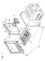
- a display apparatus comprises a housing 10, a cathode ray tube 20, an electron gun unit 30 which emits an electron beam through the cathode ray tube 20 and a video unit 40, connected to the electron gun unit 30, for supplying a video signal to the cathode ray tube 20.
- a printed circuit board (PCB) 51 for supplying an electrical signal to the cathode ray tube 20 is mounted on a substrate frame 50.
- the housing 10 surrounding the cathode ray tube 20 includes a front casing 10a and a rear casing 10b which are fastened together by a snap-fitting arrangement comprising a plurality of projections 14, located in an upper part of the front casing 10a and a plurality of snap-holders on an upper part of the front of the rear casing 10b.
- An opening 12 is provided in the front casing 10a for viewing a picture displayed on a screen 20a of the cathode ray tube 20.
- a support member 16 on a lower part of the front casing 10a supports a lower part of the cathode ray tube 20.
- the rear casing 10b further includes a plurality of slots 17 for dissipating heat generated by the display apparatus components.
- the cathode ray tube 20 comprises the screen 20a and an attached funnel 20b.
- a band of metal 26 extends around the circumference of the front part of the cathode ray tube 20.
- An attachment member 27 is provided at each corner of the band 26. Each attachment member comprises a screw hole for receiving a boss (not shown) protruding from the rear of the front casing 10a.
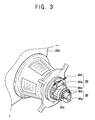
- the electron gun unit 30 is mounted on the neck 20c of the cathode ray tube 20.
- the electron gun unit 30 emits an electron beam which collides with monochrome or red, green and blue (RGB) fluorescent materials of monochrome or RGB (red, green, blue) colours coated on an inner surface of the screen 20a, thereby displaying a picture.
- RGB red, green, blue
- the electron gun unit 30 includes an insertion part (not shown) placed within the neck 20c of the cathode ray tube 20, and a boss 30a provided at the rear of the insertion part, protruding from the neck 20c.
- the boss 30a has a non-circular cross-section to prevent rotation of the video unit 40 when the boss 30a is placed in a boss holder 45 (see Figure 5).
- a plurality of pins 30b are located around the boss 30a for insertion into pinholes 46 (see Figure 5) provided on the boss holder 45, providing electrical connections therebetween.
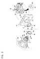
- the video unit 40 comprises a shield member 41 made of metal, which forms part of the outer surface of the video unit 40, a reinforcement member 42 attached to the rear of the shield member 41 and a video PCB 44 fastened to the rear of the shield member 41 by bolts 47.
- An aperture 41a is provided in a central area at the front of the shield member 41, through which the neck 20c and the boss 30a of the electron gun unit 30 are inserted.
- a plurality of hook holes 41b situated around the aperture 41a receive the hooks 42d on the reinforcement member.
- the reinforcement member 42 has a main body 42a with an opening at its centre.
- a plurality of ribs 42b are provided on the main body 42a and extend through the aperture 41a when the reinforcement member 42 is attached to the shield member 41.
- the ribs 42b are placed around the aperture 41a and support a second clamp member 70 (to be described later).
- a hook 42c is provided at an end of each rib 42b. The hooks 42c selectively lock into a notch 70d and hook holes 70e on the second clamp member 70. Thus, the second clamp member 70 is held by the ribs 42b.
- the boss holder 45 is mounted on the video PCB 44 and is shaped to correspond with, and receive, boss 30a. Pin holes 46 on the boss holder 45 receive pins 30b provided on the electron gun unit 30 for electric connection therebetween.
- Clamp members 60 and 70 are attached to the electron gun unit 30 and the video unit 40 and fastened to each other to prevent separation of the two units 30, 40.
- the clamp member provided on the electron gun unit 30 will be referred to as the first clamp member 60
- the clamp member provided at the video unit 40 will be called the second clamp member 70.
- the first clamp member 60 is comprised of a ring-shaped first clamp main body 60a and first tightening members 60b and 60d connecting opposite ends 60e and 60f of the first clamp main body 60a so as to fasten the first clamp main body 60a around the neck 20c of the cathode ray tube 20.
- first clamp main body 60a On the first clamp main body 60a are a plurality of holes 60c to which pins 70c of the second clamp main body 70a are locked.
- Each hole 60c has an elongated shape, so that each pin 70c can be easily locked into the hole 60c.
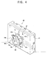
- the second clamp member 70 is comprised of a second clamp main body 70a for mounting on the plurality of ribs 42b of the video unit 40 and a second tightening member 70b connecting opposite ends 70f and 70g of the second clamp main body 70a, thereby keeping the pins 70c located on the second clamp main body 70a from coming out of the holes 60c of the first clamp member 60 when the clamp members are locked together.
- the second clamp main body 70a also includes the notch 20d and hook holes 70e in which the hooks 42c provided at the end parts of the ribs 42b are locked.
- the first clamp main body 60a of the first clamp members 60 is placed around the neck 20c.
- the opposite ends 60e and 60f of the first clamp main body 60a are then connected to each other by means of the tightening members 60b and 60d, thereby fastening the first clamp main body 60a on the neck 20c.
- the second clamp main body 70a of the second clamp member 70 is mounted on the ribs 42b of the video unit 40. That is, the hooks 42c provided at the ends of the ribs 42b are hooked onto the notch 70d and the hook holes 70e.
- the boss 30a of the electron gun unit 30 is inserted into the boss holder 45 of the video PCB 44 through the aperture 41a of the video unit 40, plugging the pins 30b of the electron gun unit 30 into the pin holes 46 provided on the video PCB 44. Then, the pins 70c on the second clamp main body 70a are hooked onto the holes 60c of the first clamp main body 60a. The second tightening member 70b is then tightened so as to urge the opposite ends 70f and 70g of the second clamp main body 70a together, thereby keeping the pins 70c from coming out of the holes 60c. Thus, the fastening of the electron gun unit 30 to the video unit 40 is completed.
- first and second clamp members 60 and 70 are mounted on the electron gun unit 30 and the video unit 40 respectively, thereby providing means for attaching the video unit 40 and the electron gun unit 30 and preventing their separation. Moreover, this arrangement should not cause breakage of the neck 20c of the cathode ray tube 20.
Landscapes
- Engineering & Computer Science (AREA)
- Multimedia (AREA)
- Signal Processing (AREA)
- Vessels, Lead-In Wires, Accessory Apparatuses For Cathode-Ray Tubes (AREA)
- Manufacture Of Electron Tubes, Discharge Lamp Vessels, Lead-In Wires, And The Like (AREA)
Applications Claiming Priority (2)
| Application Number | Priority Date | Filing Date | Title |
|---|---|---|---|
| KR10-2001-0037073A KR100395638B1 (ko) | 2001-06-27 | 2001-06-27 | 디스플레이장치 |
| KR2001037073 | 2001-06-27 |
Publications (2)
| Publication Number | Publication Date |
|---|---|
| EP1278377A2 true EP1278377A2 (de) | 2003-01-22 |
| EP1278377A3 EP1278377A3 (de) | 2004-03-24 |
Family
ID=19711410
Family Applications (1)
| Application Number | Title | Priority Date | Filing Date |
|---|---|---|---|
| EP01307851A Withdrawn EP1278377A3 (de) | 2001-06-27 | 2001-09-14 | Anzeigevorrichtung |
Country Status (7)
| Country | Link |
|---|---|
| US (1) | US6633140B2 (de) |
| EP (1) | EP1278377A3 (de) |
| JP (1) | JP3706569B2 (de) |
| KR (1) | KR100395638B1 (de) |
| CN (1) | CN1152565C (de) |
| MX (1) | MXPA01009219A (de) |
| MY (1) | MY134108A (de) |
Families Citing this family (4)
| Publication number | Priority date | Publication date | Assignee | Title |
|---|---|---|---|---|
| KR100420654B1 (ko) * | 2001-10-15 | 2004-03-02 | 엘지전자 주식회사 | 영상표시기기의 영상유닛 소켓 이탈방지장치 |
| US7209345B2 (en) * | 2003-10-16 | 2007-04-24 | Richco Inc. | Cathode ray tube clamp |
| KR100577430B1 (ko) * | 2004-09-03 | 2006-05-08 | 삼성전자주식회사 | 디스플레이 장치 |
| KR101135889B1 (ko) * | 2006-01-23 | 2012-04-13 | 삼성전자주식회사 | 디스플레이장치 및 그 제조방법 |
Family Cites Families (11)
| Publication number | Priority date | Publication date | Assignee | Title |
|---|---|---|---|---|
| US4338635A (en) * | 1980-06-03 | 1982-07-06 | Audiotronics Video Display Division, Inc. | Cathode ray tube monitor |
| US4687966A (en) * | 1986-08-27 | 1987-08-18 | Rca Corporation | Deflection yoke for adhesive assembly and mounting |
| KR910009637B1 (ko) * | 1987-12-26 | 1991-11-23 | 가부시끼가이샤 도시바 | 칼라 수상관 장치 |
| US5350978A (en) * | 1993-02-10 | 1994-09-27 | Chunghwa Picture Tubes, Ltd. | Multi-beam group electron gun for color CRT |
| GB2275400B (en) * | 1993-02-23 | 1996-11-27 | Rank Brimar Ltd | Cathode ray tube packages |
| KR970003294Y1 (ko) * | 1994-05-30 | 1997-04-14 | 삼성전자 주식회사 | 음극선관의 네크부 고정구조 |
| KR0141449B1 (ko) * | 1994-12-02 | 1998-08-17 | 김광호 | 전자제품의 음극선관용 pcb 결합장치 |
| KR100225045B1 (ko) * | 1996-05-13 | 1999-10-15 | 구자홍 | 영상표시기기의 전면 전계 복사 노이즈 차단 장치 |
| KR200162382Y1 (ko) * | 1996-08-20 | 1999-12-15 | 윤종용 | 모니터의 비데오 pcb 어셈블리 결착장치 |
| JPH11312565A (ja) * | 1998-04-28 | 1999-11-09 | Sony Corp | 回路基板装置及びこの回路基板装置を用いた画像表示装置 |
| KR100283939B1 (ko) * | 1999-02-13 | 2001-02-15 | 윤종용 | 모니터의 비디오 쉴드 |
-
2001
- 2001-06-27 KR KR10-2001-0037073A patent/KR100395638B1/ko not_active Expired - Fee Related
- 2001-08-30 MY MYPI20014085 patent/MY134108A/en unknown
- 2001-09-12 MX MXPA01009219A patent/MXPA01009219A/es active IP Right Grant
- 2001-09-14 EP EP01307851A patent/EP1278377A3/de not_active Withdrawn
- 2001-09-28 CN CNB011360216A patent/CN1152565C/zh not_active Expired - Fee Related
- 2001-10-29 JP JP2001330790A patent/JP3706569B2/ja not_active Expired - Fee Related
- 2001-11-30 US US09/996,817 patent/US6633140B2/en not_active Expired - Fee Related
Also Published As
| Publication number | Publication date |
|---|---|
| CN1394080A (zh) | 2003-01-29 |
| MY134108A (en) | 2007-11-30 |
| US20030001525A1 (en) | 2003-01-02 |
| US6633140B2 (en) | 2003-10-14 |
| JP2003032575A (ja) | 2003-01-31 |
| CN1152565C (zh) | 2004-06-02 |
| KR20030001728A (ko) | 2003-01-08 |
| JP3706569B2 (ja) | 2005-10-12 |
| KR100395638B1 (ko) | 2003-08-21 |
| EP1278377A3 (de) | 2004-03-24 |
| MXPA01009219A (es) | 2003-08-20 |
Similar Documents
| Publication | Publication Date | Title |
|---|---|---|
| US7864263B2 (en) | Thin display apparatus | |
| US20050264985A1 (en) | Plasma display device | |
| EP1278377A2 (de) | Anzeigevorrichtung | |
| US5592045A (en) | Auxiliary coil fastener in a deflection yoke | |
| US6894732B2 (en) | Display apparatus having improved interconnection to video printed circuit board | |
| US5343111A (en) | Cathode ray tube and degaussing coil employed therein | |
| CA1267682A (en) | Deflection yoke for adhesive assembly and mounting | |
| KR100392459B1 (ko) | 디스플레이장치 | |
| US6795131B1 (en) | Structure for fastening flat braun tube to cabinet | |
| US6773274B2 (en) | Mounting arrangement for CRT socket board | |
| KR20040008859A (ko) | 디스플레이장치 | |
| KR20040009336A (ko) | 디스플레이장치 | |
| US7301585B2 (en) | Display apparatus | |
| KR0136475Y1 (ko) | 소자코일 고정장치 | |
| JP3371181B2 (ja) | フラット型テレビ受像機 | |
| JPH0562615A (ja) | 実装基板の取付構造 | |
| KR100483615B1 (ko) | 밴트리스 타입의 편향 요크 | |
| KR970006012Y1 (ko) | 디가우징 코일 고정장치 | |
| KR19980022394U (ko) | 모니터에 설치되는 디가우싱 코일의 고정 홀더 | |
| KR20040013317A (ko) | 디스플레이장치 | |
| US20030001980A1 (en) | Display apparatus | |
| US20080061672A1 (en) | Cathode Ray Tube Deflection Yoke Securing Device | |
| JP2002320241A (ja) | 陰極線管装着装置 | |
| JPH07264612A (ja) | 受像機 | |
| JP2000307975A (ja) | テレビジョン受像機におけるアンテナ取付構造 |
Legal Events
| Date | Code | Title | Description |
|---|---|---|---|
| PUAI | Public reference made under article 153(3) epc to a published international application that has entered the european phase |
Free format text: ORIGINAL CODE: 0009012 |
|
| AK | Designated contracting states |
Kind code of ref document: A2 Designated state(s): AT BE CH CY DE DK ES FI FR GB GR IE IT LI LU MC NL PT SE TR |
|
| AX | Request for extension of the european patent |
Free format text: AL;LT;LV;MK;RO;SI |
|
| PUAL | Search report despatched |
Free format text: ORIGINAL CODE: 0009013 |
|
| AK | Designated contracting states |
Kind code of ref document: A3 Designated state(s): AT BE CH CY DE DK ES FI FR GB GR IE IT LI LU MC NL PT SE TR |
|
| AX | Request for extension of the european patent |
Extension state: AL LT LV MK RO SI |
|
| RAP1 | Party data changed (applicant data changed or rights of an application transferred) |
Owner name: SAMSUNG ELECTRONICS CO., LTD. |
|
| 17P | Request for examination filed |
Effective date: 20040925 |
|
| AKX | Designation fees paid |
Designated state(s): DE FR GB IT NL |
|
| 17Q | First examination report despatched |
Effective date: 20050609 |
|
| 17Q | First examination report despatched |
Effective date: 20050609 |
|
| 17Q | First examination report despatched |
Effective date: 20050609 |
|
| GRAP | Despatch of communication of intention to grant a patent |
Free format text: ORIGINAL CODE: EPIDOSNIGR1 |
|
| STAA | Information on the status of an ep patent application or granted ep patent |
Free format text: STATUS: THE APPLICATION IS DEEMED TO BE WITHDRAWN |
|
| 18D | Application deemed to be withdrawn |
Effective date: 20080917 |