Technical Field
-
The present invention relates to a decoding apparatus
used in a digital mobile communication system.
Background Art
-
In a reception side apparatus of a digital mobile
communication system, usually, a demodulated data is
obtained by carrying out the following processing. First,
from a reception signal received over a propagation path,
i.e., a phase modulated signal (a signal modulated by
predetermined phase modulation method in a transmission
side apparatus), a wave shape distortion caused by delay
waves, etc. is compensated for by an equalizer. Next, using
the phase modulated signal of which wave shape distortion
was compensated for, a decoding processing is executed by
decoding apparatus. Finally, an error correction decoding
processing is performed on the signal obtained after
decoding processing. Thus, the demodulated data of which
the error that is occurred in a propagation path was
corrected is obtained.
-
The aforementioned decoding processing are carried
out specifically as given below. FIG. 1 is a diagram
illustrating a signal space diagram of 8PSK used by a
conventional decoding apparatus.
-
In a conventional decoding apparatus, threshold
values A-D are set in the signal space diagram of 8PSK as
shown in FIG. 1, and decoding processing are then executed.
Specifically, a decision (positive/negative decision) on
the I signal in the signal of which wave shape distortion
was compensated for by an equalizer (hereinafter, it is
referred to as "I signal") whether it has positive or
negative value is carried out.
-
Next, a decision whether the Q signal in the signal
of which a wave shape distortion was compensated for by
an equalizer (hereinafter, it is referred to as "Q signal")
is larger than threshold value A is carried out by a decision
circuit. When Q signal is larger than threshold value A,
a symbol becoming a decoding point is decided uniquely as
(0,1,0).
-
When Q signal is smaller than threshold value A, a
decision whether Q signal is larger than threshold value
B is carried out by decision circuit. When Q signal is larger
than threshold value B whereas I signal is determined to
have a positive value in the above-mentioned
positive/negative decision, a symbol becomes a decoded
object is determined as (0,1,1), and when I signal is
determined to have a negative value in the above-mentioned
positive/negative decision, a symbol becomes a decoded
object is determined as (0,0,0).
-
When Q signal is smaller than threshold value B, a
decision whether Q signal is larger than threshold value
C is carried out by decision circuit. When Q signal is larger
than threshold value C whereas I signal is determined to
have a positive value in the above-mentioned
positive/negative decision, a symbol becomes a decoded
object is determined as (1,1,1), and when I signal is
determined to have a negative value in the above-mentioned
positive/negative decision, a symbol becomes a decoded
object is determined as (0,0,1).
-
When Q signal is smaller than threshold value C, a
decision whether Q signal is larger than threshold value
D is carried out by decision circuit. When Q signal is larger
than threshold value D whereas I signal is determined to
have a positive value in the above-mentioned
positive/negative decision, a symbol becomes a decoded
object is determined as (1,1,0), and when I signal is
determined to have a negative value in the above-mentioned
positive/negative decision, a symbol becomes a decoded
object is determined as (1,0,1). When a Q signal is less
than threshold value D, a symbol becomes a decoded object
is determined uniquely as (1,0,0).
-
In the execution of processing such as
described-above, a phase modulated signal can be decoded
as a symbol unit.
-
However, problems, as explained below, exist in the
conventional decoding apparatus . First, in order to realize
the decoding of a phase modulated signal, a large number
of decision circuits such as decision circuits used for
deciding whether such a phase modulated signal is larger
than a threshold value, decision circuits used for executing
positive/negative decision of the phase modulated signal,
etc. become necessary in the aforementioned conventional
decoding apparatus. As a result, the size of conventional
decoding apparatus and the amount of calculations become
impractically large.
-
Second, in an error correction decoding apparatus
which performs an error correction decoding on the signal
decoded by the aforementioned conventional decoding
apparatus, it is preferred to perform error correction
decoding using not only the decoded symbol but also the
likelihood of each bit included in such a symbol, rather
than performing error correction decoding using only the
decoded symbol because it is possible to generate a
demodulated data with a remarkably high precision. That
is to say, the aforementioned conventional decoding
apparatus is required to output not only the decoded symbol
but also the likelihood of each bit included in such a symbol
to the error correction decoding apparatus in order to
improve the precision of the demodulated data obtained by
error correction decoding. However, the aforementioned
conventional decoding apparatus is required to provide
circuits which calculate the likelihood of each bit included
in the symbol separately because the phase modulated signal
is decoded in a symbol unit. Thus, the size of conventional
decoding apparatus and amount of calculations become
impractically large.
Disclosure of Invention
-
It is an object of the present invention to provide
a decoding apparatus that can carry out decoding of a phase
modulated signal while keeping the apparatus size and
calculations amount. Moreover, the present invention is
to provide a decoding apparatus to calculate the likelihood
of each bit included in a decoded symbol while keeping the
apparatus size and calculations amount.
-
Such an object is achieved by decoding a phase
modulated signal transmitted by a transmission side
apparatus based on the locations of signal points with the
same predetermined bit value in a mapping symbol that is
based on M-ary phase modulation method applied by the
transmission side apparatus.
Brief Description of Drawings
-
- FIG. 1 is a schematic diagram illustrating a signal
space diagram of 8PSK used by a conventional decoding
apparatus;
- FIG. 2A is a schematic diagram illustrating a state
of a signal space diagram of 8PSK used by a decoding apparatus
according to Embodiment 1 of the present invention;
- FIG. 2B is a schematic diagram illustrating a state
of a signal space diagram of 8PSK used by a decoding apparatus
according to Embodiment 1 of the present invention;
- FIG. 3 is a schematic diagram illustrating a state
of a signal space diagram of 8PSK used by a decoding apparatus
according to Embodiment 1 of the present invention;
- FIG. 4 is a block diagram showing a configuration
of a decoding apparatus according to Embodiment 1 of the
present invention;
- FIG. 5 is a schematic diagram illustrating a state
of a signal space diagram of π/4 shift 4PSK used by a decoding
apparatus according to Embodiment 1 of the present
invention;
- FIG. 6 is a schematic diagram illustrating a state
of a signal space diagram of an initial phase rotated 8PSK
used by a decoding apparatus according to Embodiment 1 of
the present invention;
- FIG. 7 is a block diagram showing a configuration
of a decoding apparatus according to Embodiment 2 of the
present invention;
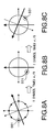
- FIG. 8A is a schematic illustration of an exemplary
state of a symbol mapping which rotates every symbol;
- FIG. 8B is a schematic illustration of an exemplary
state of a symbol mapping which rotates every symbol;
- FIG. 8C is a schematic illustration of an exemplary
state of a symbol mapping which rotates every symbol;
- FIG. 9 is a block diagram showing a configuration
of a decoding apparatus according to Embodiment 3 of the
present invention;
- FIG. 10 is a block diagram showing a configuration
of an equalizer which outputs a phase modulated signal to
a decoding apparatus according to Embodiment 4 of the present
invention;
- FIG. 11 is a block diagram showing a configuration
of a DFE-type equalizer which outputs a phase modulated
signal to a decoding apparatus according to Embodiment 5
of the present invention;
- FIG. 12 is a block diagram showing a configuration
of an MLSE-type equalizer which outputs a phase modulated
signal to a decoding apparatus according to Embodiment 6
of the present invention;
- FIG. 13A is a schematic diagram illustrating a state
of a signal space diagram of 8PSK used by a decoding apparatus
according to Embodiment 7 of the present invention;
- FIG. 13B is a schematic diagram illustrating a state
of a signal space diagram of 8PSK used by a decoding apparatus
according to Embodiment 7 of the present invention;
- FIG. 14 is a schematic diagram illustrating a state
of a signal space diagram of 8PSK used by a decoding apparatus
according to Embodiment 7 of the present invention; and
- FIG. 15 is a block diagram showing a configuration
of a decoding apparatus according to Embodiment 7 of the
present invention.
-
Best Mode for Carrying out the Invention
-
Hereinafter, embodiments of the present invention
will be specifically described with reference to the
accompanying drawings.
(Embodiment 1)
-
First, a brief explanation of a decoding apparatus
according to the present embodiment will be given below.
A transmission side apparatus which is a decoding apparatus
of a communication partner according to the present
embodiment generates a phase modulated signal by performing
modulation using a predetermined M-ary phase modulation
method on a transmission signal subjected to an error
correction coding. This transmission side apparatus
transmits the generated phase modulated signal according
to a decoding apparatus of the present embodiment
(hereinafter, it is referred to as "decoding apparatus").
-
A decoding apparatus receives a phase modulated
signal transmitted over a propagation path by a transmission
side apparatus. In addition, a decoding apparatus
compensates for wave shape distortion in the received phase
modulated signal (reception signal) by an equalizer. Then,
a decoding apparatus carries out a decoding of the phase
modulated signal of which wave shape distortion was
compensated for. In particular, such a decoding apparatus
carries out the decoding based on the locations of signal
points with the same predetermined bit value in a symbol
mapping that is based on M-ary phase modulation method used
by transmission side apparatus.
-
The case when using 8PSK modulation as an M-ary phase
modulation method in the present embodiment will be
explained below with reference to FIG. 2A, FIG. 2B and FIG.
3. FIG. 2A, FIG. 2 B and FIG. 3 are schematic diagrams
illustrating the state of signal space diagram of 8PSK
(symbol mapping based on 8PSK) used by the decoding apparatus
according to Embodiment 1 of the present invention. Each
symbol (each signal point) includes 3 bits in the symbol
mapping based on 8PSK. In FIG. 2A, FIG. 2B and FIG. 3, signal
point 101 to signal point 108 are located in a plane
(hereinafter, it is referred to as "I-Q plane") which is
formed by making the standard axis of an in-phase component
as I-axis 110 and the standard axis of a quadrature component
as Q-axis 111. Here, each signal point includes 3 bits,
the most bit, medium bit and least bit which are expressed,
respectively, by "bit 3N", "bit 3N+1" and "bit 3N+2".
-
First, paying attention to bit 3N of each signal point
referring to FIG. 2A, signal points in which bit 3N is "0"
are signal point 102 to signal point 105 whereas signal
points in which bit 3N is "1" are signal point 106 to signal
point 108 and signal point 101.
-
In other words, the signal point in which bit 3N is
"0" is located in a domain formed I' axis 112 as a standard
in the upper-half direction of the figure, and the signal
point in which bit 3N is "1" is located in a domain formed
I' axis as a standard in lower-half direction of the figure.
The I' axis 112 (Q' axis 113) is obtained by rotating the
I axis 110 (Q axis 111) with phase only π/8 anticlockwise
around the original point O.
-
That is to say, the signal points in which bit 3N
is "0" are equivalent to the signal points which have
positive values of Q' component whereas the signal points
in which bit 3N is "1" is equivalent to the signal points
which have negative values of Q' component.
-
The Q' component (I' component) is equivalent to the
signal point of quadrature component (in-phase component)
allocated in the plane formed by I' axis 112 and Q' axis
113 (hereinafter, it is referred to as "I'-Q' plane).
-
Considering the locations related to signal points
of the same value of bit 3N in the symbol mapping, if Q'
component in the I'-Q' plane of the phase modulated signal
of which wave shape distortion was compensated for is
positive, the bit 3N included in the symbol which becomes
a decoded object can be decoded as "0". Similarly, if Q'
component in the I'-Q' plane of the phase modulated signal
of which wave shape distortion was compensated for is
negative, the symbol which becomes a decoded object and
includes bit 3N can be decoded as "1".
-
In addition, the I' axis 112 is determined as in the
following example. The mutual distance between the signal
point of which bit 3N is "0" (for instance, signal point
102) and the signal point of which bit 3N is "1" (for instance,
signal point 101) which becomes small is detected, and the
axis passing through the middle point in the distance between
every signal point and the original point O becomes I' axis
112.
-
Next, paying attention to bit 3N+1 of each signal
point referring to FIG. 2B, signal points in which bit 3N+1
is "1" are signal point 101 to signal point 103 and signal
point 108 whereas signal points in which bit 3N+1 is "0"
are signal point 104 to signal point 107.
-
In other words, the signal points in which bit 3N+1
is "1" is located in a domain formed Q' axis 113 as a standard
in upper-half direction of the figure, and the signal points
in which bit 3N+1 is "0" is located in a domain formed Q'
axis as a standard in lower-half direction of the figure.
-
In other words, the signal points in which bit 3N+1
is "1" are equivalent to the signal points which have
positive value of I' component whereas the signal points
in which bit 3N+1 is "0" is equivalent to the signal points
which have negative value of I' component.
-
Considering the location related to signal points
of the same value of bit 3N+1 in such a symbol mapping,
if I' component in the I'-Q' plane of the phase modulated
signal of which wave shape distortion was compensated for
is positive, the bit 3N+1 included in the symbol which
becomes a decoded object can be decoded as "1". Similarly,
if I' component in the I'-Q' plane of the phase modulated
signal of which wave shape distortion was compensated for
is negative, the bit 3N+1 included in the symbol which
becomes a decoded object can be decoded as "0".
-
In addition, the Q' axis 113 is determined as in the
following example. The mutual distance between the signal
point of which bit 3N+1 is "0" (for instance, signal point
104) and the signal point of which bit 3N+1 is "1" (for
instance, signal point 103) which becomes small is detected,
and the axis passing through the middle point in the distance
between every signal point and the original point O becomes
Q' axis 113.
-
Next, paying attention to bit 3N+2 of each signal
point referring to FIG. 3, signal points in which bit 3N+2
is "1" are the signal point 101, signal point 102, signal
point 105 and signal point 106 whereas signal points in
which bit 3N+2 is "0" are signal point 103, signal point
104, signal point 107 and signal point 108.
-
That is to say, signal points in which bit 3N+2 is
"1" are equivalent to signal points of which |I' component|
> |Q' component| whereas signal points in which bit 3N+2
is "0" are equivalent to signal points of which |I'
component| < |Q' component|.
-
Considering the locations related to signal points
of the same value of bit 3N+2 in such a symbol mapping,
if the absolute value of I' component is larger than the
absolute value of Q' component in the I'-Q' plane of the
phase modulated signal of which wave shape distortion was
compensated for, the bit 3N+2 included in the symbol which
becomes a decoded object can be decoded as "1". Similarly,
if the absolute value of Q' component is larger than the
absolute value of I' component in the I'-Q' plane of the
phase modulated signal of which wave shape distortion was
compensated for, the bit 3N+2 included in the symbol which
becomes a decoded object can be decoded as "0".
-
According to the aforementioned such a decoding, each
bit (bit 3N to bit 3N+2) included in the symbol which becomes
a decoded object can be decoded.
-
With reference to FIG. 4, specific configuration of
the decoding apparatus realizes decoding as described above
will be explained below. FIG. 4 is a block diagram showing
a configuration of a decoding apparatus according to
Embodiment 1 of the present invention.
-
In FIG. 4, I signal (I component) and Q signal (Q
component) in a phase modulated signal of which a wave shape
distortion is compensated for by an equalizer not shown
in the figure are inputted into converting section 201.
A conversion of I signal and Q signal in the phase modulated
signal is executed in converting section 201. In other words,
in converting section 201, I signal and Q signal perform
an I-Q plane are converted into I' signal and Q' signal
to perform an I'-Q' plane, respectively. That is to say,
the I signal and Q signal shown by the I-Q plane are converted,
respectively, into I' signal and Q' signal shown by the
I'-Q' plane in converting section 201. Specifically,
referring to FIG. 2A, for instance, when a phase modulated
signal corresponds to signal point 102 is inputted into
converting section 201, the I signal of such a phase
modulated signal is converted from I1 shown by I-Q plane
into I1' shown by I'-Q' plane. Similarly, the Q signal of
such a phase modulated signal is converted from Q1 shown
by I-Q plane into Q1' shown by I'-Q' plane. Such a conversion
is equivalent to rotating the phase of the phase modulated
signal by only π/8 in anticlockwise direction. According
to such a conversion, I' signal and Q' signal are obtained
in converting section 201.
-
The obtained I' signal is outputted to
positive/negative decision section 202 and absolute value
calculating section 203. The obtained Q' signal is outputted
to positive/negative decision section 205 and absolute
value calculating section 204.
-
A positive/negative decision is carried out on the
I' signal in positive/negative decision section 202. As
a result of such positive/negative decision, when an I'
signal is of positive value, "1" is outputted as bit 3N+1
to parallel/serial (it is referred to as "P/S") converting
section 207, while when I' signal is of negative value,
"0" is outputted as bit 3N+1 to P/S converting section 207.
In other words, a code bit in the I' signal is just outputted
as bit 3N+1 to P/S converting section 207 from
positive/negative decision section 202.
-
A positive/negative decision is carried out on the
Q' signal in positive/negative decision section 205. As
a result of such positive/negative decision, when Q' signal
is of positive value, "0" is outputted as bit 3N to P/S
converting section 207 whereas if Q' signal is a negative
number, "1" is outputted as bit 3N. In other words, a value
that reverse the rotation of the code bit in the Q' signal
is just outputted as bit 3N to P/S converting section 207
from positive/negative decision section 205.
-
The absolute value of the I' signal is calculated
in absolute value calculating section 203. The obtained
absolute value of the I' signal is outputted to subtractor
206. The absolute value of the Q' signal is calculated in
absolute value calculating section 204. The obtained
absolute value of the Q' signal is outputted to subtractor
206.
-
A subtraction is carried out in subtractor 206 using
the absolute value of I' signal and absolute value of Q'
signal, i.e., carrying out |I' signal| - |Q' signal|. As
a result of such subtraction, when |I' signal| > |Q' signal|,
"1" is outputted as bit 3N+2 to P/S converting section 207,
while when |I' signal| < |Q' signal|, "0" is outputted as
bit 3N+2 to P/S converting section 207. That is to say,
the code bit in the signal obtained by subtraction calculated
in subtractor 206 is just outputted as bit 3N+2 to P/S
converting section 207.
-
Bit 3N from positive/negative decision section 205,
bit 3N+1 from positive/negative decision section 202 and
bit 3N+2 from subtractor 206 are rearranged in P/S converting
section 207. Then, bit 3N, bit 3N+1 and bit 3N+2 are outputted
sequentially from P/S converting section 207.
-
In addition, the aforementioned explained decoding
can be realized not only by hardware but it can be realized
by CPU microprocessors or monolithic IC such as LSI, etc.
-
In the decoding apparatus according to the present
embodiment as shown above, considering the locations of
signal points with the same predetermined bit value in the
symbol mapping that is based on M-ary phase modulation method
used by a decoding apparatus in transmission side, it is
possible to decode a phase modulated signal easily by using
the in-phase/quadrature component of the phase modulated
signal and the difference between the absolute value of
in-phase component and absolute value of quadrature
component of the phase modulated signal. It is possible
to keep the apparatus size and calculations amount of the
decoding apparatus according to the present embodiment
because a decision circuits become unnecessary when
decoding a phase modulated signal.
-
In addition, in the present embodiment, although a
case when using 8PSK as an M-ary phase modulation method
was explained, but the present invention can be applied
also to the case when using any other M-ary phase modulation
method beside the 8PSK method (for example, 4PSK method,
16PSK method, etc.). In this case, considering locations
of signal points with the same predetermined bit value in
symbol mapping that is based on M-ary phasemodulationmethod,
it is possible to decode the phase modulated signal easily
if using the features inherent in such symbol mapping (for
instance, in 8ASK method, bit 3N+1 included in a symbol which
becomes a decoded object can be decoded as "1" if I' component
is positive, etc.).
-
Referring to FIG. 5, decoding method in the case when
using π/4 shift 4PSK as an M-ary phase modulation method
beside the 8PSK method will be explained below. FIG. 5 is
a schematic diagram illustrating a state of signal space
diagram of π/4 shift 4PSK (symbol mapping based on π/4
shift 4PSK) used by decoding apparatus according to
Embodiment 1 of the present invention.
-
In symbol mapping based on 4PSK, each symbol (each
signal point) includes 2 bits. Here, the most bit and least
bit are expressed, respectively, by "bit 2N" and "bit 2N+1"
in each signal point that includes 2 bits.
-
Paying attention to signal points of the same bit
2N value in symbol mapping shown in FIG. 5, signal points
in which bit 2N is "0" are signal point 301 and signal point
302 whereas signal points in which bit 2N is "1" are signal
point 303 and signal point 304. In other words, the signal
points in which bit 2N is "0" are located in a domain formed
I axis as a standard in upper-half direction of the figure,
and signal points in which bit 2N is "1" are located in
a domain formed I axis as a standard in lower-half direction
of the figure. That is to say, the signal points in which
bit 2N is "0" are equivalent to signal points which have
positive values of Q component whereas signal points in
which bit 2N is "1" are equivalent to signal points which
have negative number of Q component.
-
Considering the locations related to signal points
of the same value of bit 2N in such a symbol mapping, if
Q component in the I-Q plane of the phase modulated signal
is positive, bit 2N included in the symbol which becomes
a decoded object can be decoded as "0". Similarly, if Q
component in the I-Q plane of the phase modulated signal
is negative, bit 2N included in the symbol which becomes
a decoded object can be decoded as "1".
-
On the other hand, paying attention to signal points
of similar bit 2N+1 value in symbol mapping shown in FIG.
5, signal points in which bit 2N+1 is "0" are signal point
301 and signal point 304 whereas signal points in which
bit 2N+1 is "1" are signal point 302 and signal point 303.
In other words, signal points in which bit 2N+1 is "0" are
located in a domain formed Q axis as a standard in right-half
of the figure, and signal points in which bit 2N+1 is "1"
are located in a domain formed Q axis as a standard in
left-half of the figure. That is to say, signal points in
which bit 2N+1 is "0" are equivalent to signal points which
have positive values of I component whereas signal points
in which bit 2N+1 is "1" are equivalent to signal points
which have negative number of I component.
-
Considering the locations related to signal points
of the same value of bit 2N+1 in such a symbol mapping,
if I component in the I-Q plane of the phase modulated signal
is positive, bit 2N+1 included in the symbol which becomes
a decoded object can be decoded as "0". Similarly, if I
component in the I-Q plane of the phase modulated signal
is negative, bit 2N+1 included in the symbol which becomes
a decoded object can be decoded as "1".
-
Moreover, it is possible to decode easily a phase
modulated signal not only in the case when using π/4 shift
4PSK method, but also in the case when using 4PSK method
as paying attention to the locations of signal points with
the same predetermined bit value in the symbol mapping that
is based on 4PSK method.
(Embodiment 2)
-
In Embodiment 1, initial phase of the symbol mapping
in the received phase modulated signal is detected, the
case when executing a decoding based on the detected initial
phase in Embodiment 2 of the present invention will be
explained.
-
The decoding apparatus according to the
aforementioned Embodiment 1 is in synchronous with
transmission side apparatus when starting communication.
Thus, symbol mapping in a decoding apparatus coincide with
symbol mapping in a transmission side apparatus. However,
there is a case where the state of the symbol mapping in
a decoding apparatus rotates into a symbol mapping in a
transmission side apparatus because of the influence of
propagation path during reception. Such a case will be
explained with reference to FIG. 6. FIG. 6 is a schematic
diagram illustrating a state of a signal space diagram of
a rotated initial phase 8PSK which is used by a decoding
apparatus according to Embodiment 1 of the present
invention.
-
As shown in FIG. 6, initial phase of symbol mapping
in a decoding apparatus, by the effect of propagation path,
in comparison to initial phase of symbol mapping of a
transmission side apparatus (refers to FIG. 2A) is rotated
180 degree. In this case, if a decoding apparatus uses a
method explained in Embodiment 1, it is expected that a
wrong decoding is carried out. Specifically, in the case
when initial phase is not rotated as shown in FIG. 2A, if
Q' component in the I'-Q' plane of the phase modulated signal
is positive, it is possible to decode correctly bit 3N as
"0". However, in the case when initial phase is rotated
180 degree as shown in FIG. 6, if Q' component in the I'-Q'
plane of the phase modulated signal is positive, bit 3N
is erroneously decoded as "0" despite the fact that original
bit 3N should be decoded as "1".
-
The decoding apparatus according to the present
embodiment, detects the phase rotation amount of the symbol
mapping in the received phase modulated signal using any
known signal transmitted by a transmission side apparatus
even after acquiring synchronization with such a
transmission side apparatus, and the decoding is carried
out based on the detection result.
-
A configuration of a decoding apparatus according
to the present invention will be explained with reference
to
FIG. 7. FIG. 7 is a block diagram showing a configuration
of a decoding apparatus according to Embodiment 2 of the
present invention. In addition, sections in FIG. 7 which
are similar to those in FIG. 4 are assigned similar reference
numerals and explanations thereof will be omitted.
-
In FIG. 7, initial phase detecting section 501 detects
the initial phase of symbol mapping in a phase modulated
signal by detecting the phase rotation amount of the symbol
mapping in the phase modulated signal using any known signal
transmitted by transmission side apparatus. Such an initial
phase detecting element 501 notifies positive/negative
decision section 502 and positive/negative decision
section 503 of the detected initial phase.
-
Positive/negative decision section 502 has a
configuration similar to positive/negative decision
section 202 shown in FIG. 4 except the following point.
That is, positive/negative decision section 502 outputs
bit 3N+1 to P/S converting section 207 using the initial
phase detected by initial phase detecting section 501.
Specifically, in the case when initial phase is rotated
180 degree as shown in FIG. 6, if I' component in the I'-Q'
plane of the phase modulated signal is positive, bit 3N+1
is decoded as "0" and decoded as "1" if I' component is
negative. In addition, it is needless to say that when
initial phase does not rotate, positive/negative decision
section 502 outputs bit 3N+1 same as positive/negative
decision section 202 in Embodiment 1. Moreover, it is needles
also to say that when initial phase rotates with any phase
except 180 degrees, positive/negative decision section 502
outputs bit 3N+1 corresponding to the phase of which initial
phase is rotated.
-
Positive/negative decision section 503 has a
configuration similar to positive/negative decision
section 205 shown in FIG. 4 except the following point.
That is, positive/negative decision section 503 outputs
bit 3N to P/S converting section 207 using the initial phase
detected by initial phase detecting section 501.
Specifically, in the case when initial phase is rotated
180 degree as shown in FIG. 6, for instance, if Q' component
in the I'-Q' plane of the phase modulated signal is positive,
bit 3N is decoded as "1" and decoded as "0" if Q' component
is negative. In addition, it is needless to say that when
initial phase does not rotate, positive/negative decision
section 503 outputs bit 3N same as positive/negative
decision section 205 in Embodiment 1. Moreover, when initial
phase rotates with any phase except 180 degrees,
positive/negative decision section 503 outputs bit 3N
corresponding to the phase of which initial phase is rotated.
-
Subtractor 504 has a configuration similar to
subtractor 206 shown in FIG. 4 except the following point.
That is, subtractor 504 outputs bit 3N+2 to P/S converting
section 207 using the initial phase detected by initial
phase detecting section 501. Specifically, when initial
phase rotates 180 degree as shown in FIG. 6, for instance,
similar to subtractor 206 in Embodiment 1, bit 3N+2 is
outputted. Moreover, it is needles to say that when initial
phase rotates with any phase except 180 degrees, subtractor
504 outputs bit 3N+2 corresponding to the phase of which
initial phase is rotated.
-
In the decoding apparatus according to the present
embodiment as shown above, considering the locations of
signal points with the same predetermined bit value in symbol
mapping that is based on an M-ary phase modulation method
used by a decoding apparatus in transmission side, it is
possible to decode a phase modulated signal easily by using
the in-phase/quadrature component of the phase modulated
signal and the difference between the absolute value of
the in-phase component and absolute value of quadrature
component of the phase modulated signal. It is possible to
keep the apparatus size and calculations amount of the
decoding apparatus according to the present embodiment
because decision circuits become unnecessary when decoding
a phase modulated signal.
-
Moreover, in decoding apparatus according to the
present embodiment, phase rotation amount of symbol mapping
in the received phase modulated signal is detected, the
initial phase is detected using the detected phase rotation
amount, and a decoding based on the detected initial phase
is carried out. Thus, it is possible to correctly decode
the phase modulated signal even in the case when there is
state rotation in the symbol mapping in a received phase
modulated signal from symbol mapping in a transmission side
apparatus caused by the influence of propagation path.
(Embodiment 3)
-
In Embodiment 3 of the present invention, the case
when demodulating the phase modulated signal which rotates
symbol mapping in Embodiment 1 every unit time will be
explained below.
-
Recently, in EDGE (Enhanced Data rate for Global
Evolution) that attracts attention as a digital radio
communication system of the next generation as shown in
FIG. 8A to FIG. 8C, the rotation of symbol mapping every
symbol in a transmission side apparatus is proposed. In
particular, considering the signal point 601, for example,
such signal point 601 moves to a location that rotates Only
3π/8 every symbol. When such a feature is applied, a decoding
apparatus according to Embodiment 1 is to receive the phase
modulated signal of which the symbol mapping rotates every
symbol. Thus, a decoding apparatus according to the present
embodiment decodes a phasemodulation signal based on symbol
mapping which rotates every unit time (here, every symbol).
-
A configuration of a decoding apparatus according
to the present invention will be explained with reference
to FIG. 9. FIG. 9 is a block diagram showing a configuration
of a decoding apparatus according to Embodiment 3 of the
present invention. In addition, sections in FIG. 9 which
are similar to those in FIG. 4 are assigned similar reference
numerals and explanations thereof will be omitted.
-
Timer 701 in FIG. 9 acquires the time corresponding
to 1 symbol then notifies logical converting section 703.
Rotation pattern generating section 702 generates rotation
pattern that shows only the phase of which symbol mapping
rotates every 1 symbol, and notifies the logical converting
section 703. In addition, it is needless to say that the
same rotation pattern generated by rotation pattern
generating section 702 are used by a transmission side
apparatus. Logical converting section 703 uses the time
acquired in timer 701 and rotation pattern generated by
rotation pattern generating section 702, estimates the
symbol mapping in the phase modulated signal presently
received, notifies estimation result to converting section
700.
-
First, converting section 700 adds both fixed
rotation amount corresponds to symbol mapping of phase
modulated signal and rotation amount based on the result
of estimation in logical converting section 703. Next,
converting section 700 uses the rotation amount obtained
by such addition, and converts I signal and Q signal in
a phase modulated signal into I' signal and Q' signal,
respectively. I' signal and Q' signal obtained by converting
section 700 are subjected to the same processing explained
in the aforementioned Embodiment 1 (FIG. 3).
-
In the decoding apparatus according to the present
embodiment as shown above, considering the locations of
signal points with the same predetermined bit value in the
symbol mapping which is based on M-ary phase modulation
method used by a decoding apparatus in transmission side,
it is possible to decode phase modulated signal easily by
using the in-phase/quadrature component of the phase
modulated signal and difference between the absolute value
of in-phase component and absolute value of quadrature
component of phase modulated signal. It is possible to keep
apparatus size and calculations amount of the decoding
apparatus according to the present embodiment because
decision circuits become unnecessary when decoding a phase
modulated signal.
-
Moreover, in decoding apparatus according to the
present embodiment, rotation pattern which is applied by
transmission side apparatus in a phase modulated signal
is restored and decoding is carried out. Accordingly, it
is possible to correctly decode a phase modulated signal
even when transmission side apparatus rotates the symbol
mapping every unit time.
-
In addition, although the case when symbol mapping
is rotated in unit time, time corresponds to 1 symbol is
explained in the present invention, but the same effect
can be obtained as described above also in the case when
using any other time as a unit time.
(Embodiment 4)
-
In Embodiment 4 of the present invention, a case when
an equalizer which outputs a phase modulated signal to
decoding apparatus when the phase modulated signal of which
the symbol mapping is rotated every symbol is decoded, uses
tap coefficients of which phase rotation corresponds to
rotation pattern and generates a phase modulated signal
of which the rotation pattern is restored in order to
compensate for wave shape distortion will be explained.
-
As described in Embodiment 3, when a phase modulated
signal of which the symbol mapping rotates every symbol
is decoded, that is to say, when a phase modulated signal
of which the symbol mapping rotates, for instance, 3π
/8 every symbol is decoded, a signal point (here, the signal
point is assumed to be (0,0,1)) can mapped into 16 positions .
In this case, such a signal point is mapped on I axis or
Q axis every 4 symbols. As a result, it is necessary for
the phase modulated signal to rotate every 4 symbol when
the phase modulated signal is decoded using a decoding
apparatus according to Embodiment 1.
-
Thus, the rotated phase modulated signal in the
decoding apparatus according to Embodiment 1 is changed
in the present embodiment, and a phase rotating is multiplied
by tap coefficients used by an equalizer. The phase
modulated signal of a rotated phase is outputted from the
equalizer. Therefore, a decoding apparatus according to the
present embodiment can demodulate the phase modulated
signal of which rotation pattern was stored so that a wave
shape distortion is compensated for by such an equalizer.
-
A configuration of an equalizer which outputs phase
modulated signal to a decoding apparatus according to the
present embodiment will be explained with reference to FIG.
10. FIG. 10 is a block diagram showing a configuration of
an equalizer which outputs a phase modulated signal to a
decoding apparatus according to Embodiment 4 of the present
invention.
-
After the phase modulated signal received via a
propagation path is subjected to predetermined radio
reception processing, it is inputted into training section
802 in equalizer 801. Training section 802
generates/updates tap coefficients using a phase modulated
signal. In addition, generating/updating of tap
coefficients in training section 802 can be realized, for
instance, by using the correlation value of the phase
modulated signal and unique word or using an impulse response
value obtained by an adaptive algorithm. The
generated/updated tap coefficients are stored in memory
807, and outputted to phase rotating section 805.
-
Rotation pattern generating section 804 generates
rotation pattern that shows only the phase of which symbol
mapping rotates every 1 symbol, and outputs the result to
phase rotating section 805. Phase rotating section 805
multiplies the phase rotation every symbol mapping by tap
coefficients from training section 802 based on rotation
pattern generated by rotation pattern generating section
804. Phase rotation which is multiplied by tap coefficients
is stored in memory 807.
-
Timer 806 acquires the time corresponding to 1 symbol
and outputs the result to memory 807. Memory 807 outputs
either phase rotation which is not multiplied by tap
coefficients in training section 802 or phase rotation which
is multiplied by tap coefficients in phase rotating section
to data demodulating section 803 according to the time
acquired by timer 806. Data demodulating section 803 not
only compensates for wave shape distortion using tap
coefficients from memory 807 and phase modulated signal
(input signal) but also outputs the phase modulated signal
of which the phase is multiplied to decoding apparatus
according to the present invention (or decoding apparatus
according to Embodiment 1, decoding apparatus having
equivalent configuration, etc.).
-
Thus, the decoding apparatus according to present
invention not only can perform phase rotation on the phase
modulated signal every symbol when phase modulated signal
of which symbol mapping rotates every symbol is demodulated
in transmission side apparatus, but also can correctly
decode such a phase modulated signal.
-
As described above, in the present embodiment, a case
when an equalizer which outputs a phase modulated signal
to decoding apparatus when the phase modulated signal of
which the symbol mapping rotates every symbol is decoded,
uses tap coefficients of which phase rotation corresponds
to rotation pattern and generates a phase modulated signal
of which rotation pattern is restored to compensate for
wave shape. As a result, a decoding apparatus according
to the present embodiment can simply demodulate the phase
modulated signal of which wave shape distortion is
compensated for by such an equalizer.
(Embodiment 5)
-
In Embodiment 5 of the present invention the case
when using a DFE (Decision Feedback Equalizer)-type
equalizer as the equalizer in Embodiment 4 will be explained
with reference to FIG. 11. FIG. 11 is a block diagram showing
a configuration of a DFE-type equalizer which outputs a
phase modulated signal to a decoding apparatus according
to Embodiment 5 of the present invention.
-
After the phase modulated signal which is received
via propagation path is subjected to predetermined
reception processing, it is inputted into training section
901 and feed forward filter (hereinafter, it is abbreviated
as FFF) 902 in a DFE-type equalizer as shown in FIG. 11.
Training section 901 carries out generating/updating of
tap coefficients using subtraction result from the
subtractor 907 to be described later and phase modulated
signal. Generated/updated tap coefficients are used by FFF
902 and feedback filter (hereinafter, it is abbreviated
as FBF) 903. The phase modulated signal which passed through
FFF 902 is outputted to phase rotating section 906.
-
Rotation pattern generating section 904 generates
rotation pattern that shows only the phase of which symbol
mapping rotates every 1 symbol, and outputs the result to
phase rotating section 906. Timer 905 acquires the time
corresponding to 1 symbol and outputs the result to phase
rotating section 906. Phase rotating section 906 acquires
the phase rotation of the phase modulated signal which passed
through FFF 902 every symbol mapping based on rotation
pattern generated by rotation pattern generating section
904 and the time acquired by timer 905. The phase modulated
signal which is acquired by phase rotation is outputted
to subtractor 907.
-
Subtractor 907 not only compensates for wave shape
distortion by executing subtraction using a phase modulated
signal acquired by phase rotation and phase modulated signal
passed through FBF 903, but also outputs the phase modulated
signal of which the phase is multiplied to decoding apparatus
according to the present invention (decoding apparatus
according to Embodiment 1, decoding apparatus having
equivalent configuration, etc.).
-
Thus, the decoding apparatus according to the present
invention not only can perform phase rotation on the phase
modulated signal every symbol when phase modulated signal
of which symbol mapping rotates every symbol is demodulated
in transmission side apparatus, but also can correctly
decode such a phase modulated signal.
-
As described above, in the present embodiment, a case
when a DFE-type equalizer which outputs a phase modulated
signal to decoding apparatus when the phase modulated signal
of which the symbol mapping rotates every symbol is decoded,
uses tap coefficients of which phase rotation corresponds
to rotation pattern and generates a phase modulated signal
of which a wave shape distortion is compensated for. As
a result, a decoding apparatus according to the present
embodiment can simply demodulate the phase modulated signal
of which the wave shape distortion is compensated for by
such a DEF-type equalizer.
(Embodiment 6)
-
In Embodiment 6 of the present invention the case
when using an MLSE (Maximum Likelihood Sequence
Estimation)-type equalizer as the equalizer in Embodiment
4 will be explained with reference to FIG. 12. FIG. 12 is
a block diagram showing a configuration of an MLSE-type
equalizer which outputs a phase modulated signal to a
decoding apparatus according to Embodiment 6 of the present
invention.
-
After the phase modulated signal which is received
via propagation path is subjected to predetermined
reception processing, it is inputted into training section
1001 in an MLSE-type equalizer and phase rotating section
1005 as shown in FIG. 12.
-
Training section 1001 carries out
generating/updating of tap coefficients using modulated
signal and subtraction result from subtractor 1006 to be
described later. The generated/updated tap coefficients
are outputted to replica generating section 1002. Replica
generating section 1002 generates a replica signal based
on tap coefficients generated/updated in training section
1001 and outputs the result to subtractor 1006.
-
Rotation Pattern generating section 1003 generates
rotation pattern which shows only the phase of which symbol
mapping rotates every 1 symbol, and outputs the result to
phase rotating section 1005. Timer 1004 acquires the time
corresponding to 1 symbol and outputs the result to phase
rotating section 1005. Phase rotating section 1005 acquires
the phase rotation of the phase modulated signal every symbol
mapping based on the rotation pattern generated by rotation
pattern generating section 1003 and the time acquired by
timer 1004. Phase modulated signal which is acquired by
phase rotation is outputted to subtractor 1006.
-
Subtractor 1006 subtracts a replica signal generated
in replica generating section 1002 from the phase modulated
signal of which a phase rotation is acquired and the
subtraction result is outputted to training section 1001
and Viterbi manipulating section 1007.
-
Viterbi manipulating section 1007 not only carries
out Viterbi manipulation in which branch metric in the path
metric of each state is calculated and the minimum path
is selected based on the calculation result, but also outputs
the phase modulated signal of which the phase is acquired
to compensate for wave shape distortion to decoding
apparatus according to the present invention (decoding
apparatus according to Embodiment 1, decoding apparatus
having a equivalent configuration, etc.).
-
Thus, the decoding apparatus according to present
invention not only can perform phase rotation on the phase
modulated signal every symbol when phase modulated signal
of which symbol mapping rotates every symbol is demodulated
in transmission side apparatus, but also can correctly
decode such a phase modulated signal.
-
As described above, in the present embodiment, a case
when an MLSE-type equalizer which outputs a phase modulated
signal to decoding apparatus when the phase modulated signal
of which the symbol mapping rotates every symbol is decoded,
uses tap coefficients of which phase rotation corresponds
to rotation pattern and generates a phase modulated signal
of which a wave shape distortion is compensated for. As a
result, a decoding apparatus according to the present
embodiment can simply demodulate the phase modulated signal
of which the wave shape distortion is compensated for by
such an MLSE-type equalizer.
(Embodiment 7)
-
The case when calculating the likelihood of each bit
included in the symbol decoded in Embodiment 1 to Embodiment
5 will be explained in Embodiment 7 of the present invention
with reference to FIG. 13A, FIG. 13B and FIG. 14. FIG. 13A,
FIG. 13B and FIG. 14 are schematic diagrams illustrating
state of signal space diagram of 8PSK (symbol mapping based
on 8PSK) used by decoding apparatus according to Embodiment
7 of the present invention. In addition, elements in FIG.
13 and FIG. 14 which are similar to those in FIG. 2 and
FIG. 3 are assigned the same reference numerals as in FIG.
2 and FIG. 3 and explanation thereof is omitted.
-
considering bit 3N in each signal point as shown in
FIG. 13A, the likelihood of bit 3N of the signal point is
of distance from I' axis 112 of such signal point. For example,
the likelihood of bit 3N of signal point 105 is of distance
1001 from I' axis 112 of this signal point 105. Such an
I' axis 112 is equivalent to the boundary line of which
bit 3N is either "0" or "1". The large (small) distance
from I' axis 112 of signal point is equivalent to large
(small) likelihood of bit 3N corresponding to such signal
point.
-
Considering bit 3N+1 in each signal point as shown
in FIG. 13B, the likelihood of bit 3N+1 of the signal point
is of distance from Q' axis 113 of such signal point. For
example, the likelihood of bit 3N+1 of signal point 105
is of distance 1002 from Q' axis 113 of this signal point
105. Such a Q' axis 113 is equivalent to the boundary line
of which bit 3N+1 is either "0" or "1". The large (small)
distance from Q' axis 113 of signal point is equivalent
to large (smal1) likelihood of bit 3N+1 corresponding to
such a signal point.
-
Considering bit 3N+2 in each signal point as shown
in FIG. 14, the likelihood of bit 3N+2 of the signal point
becomes the absolute value of the difference between the
distance from I' axis 112 of such signal point and the
distance from Q' axis 113 of this signal point. For example,
the likelihood of bit 3N+2 of signal point 105 becomes the
absolute value of the difference between distance 1002 from
Q' axis 113 of such a signal point 105 and distance 1001
from I' axis of such a signal point 105. The large (small)
difference absolute value of the distance between the
distance from I' axis 112 of the signal point and distance
from Q' axis 113 of such a signal point is equivalent to
large (small) likelihood of bit 3N+2 corresponding to such
signal point.
-
Specific configuration of the a decoding apparatus
which calculates the likelihood as described above will
be explained below with reference to FIG. 15. FIG. 15 is
a block diagram showing a configuration of a decoding
apparatus according to Embodiment 7 of the present invention.
In addition, a configuration in FIG. 15 which are similar
to that in Embodiment 1 (FIG. 4) is assigned similar
reference numerals as in FIG. 4 and explanations thereof
will be omitted.
-
In FIG. 15, the Q signal (Q component) and I signal
(I component) in a phase modulated signal of which wave
shape distortion is compensated for by a not-shown equalizer
are subjected to similar conversion to that explained in
Embodiment 1 by converting section 201. The Q' signal and
I' signal obtained by converting section 201 are outputted
to absolute value calculating section 1201 and absolute
value calculating section 1202, respectively.
-
Absolute value calculating section 1201 calculates
the absolute value of Q' signal amplitude. The calculated
absolute value of the Q' signal amplitude is equivalent
to the distance from I' axis 112 of each signal point shown
in FIG. 13A. An absolute value of this Q' signal amplitude
is outputted as a likelihood of bit 3N.
-
Absolute value calculating section 1202 calculates
the absolute value of I' signal amplitude. The calculated
absolute value of the I' signal amplitude is equivalent
to the distance from Q' axis 113 of each signal point shown
in FIG. 13B. An absolute value of this I' signal amplitude
is outputted as a likelihood of bit 3N+1.
-
Absolute value calculating section 1203 calculates
the difference of the absolute value of Q' signal amplitude
and absolute value of I' signal amplitude then calculates
the absolute value of such a difference. The calculated
difference of the absolute value is equivalent to the
absolute value of the difference between the distance from
I' axis 112 and distance from Q' axis 113 of each signal
point as shown in FIG. 14. The calculated difference of
the absolute value is outputted as a likelihood of bit 3N+2.
-
In addition, the aforementioned explained likelihood
calculation can be realized not only by hardware but it
can be realized by CPU microprocessors or monolithic IC
such as LSI, etc.
-
Thus, the likelihood calculated by a decoding
apparatus according to the present embodiment is outputted
to a not-shown error correction decoding apparatus along
with a signal (symbol) decoded by a decoding apparatus
according to either one of the Embodiment 1 to Embodiment
5. Accordingly, such an error correction decoding apparatus
can generate the demodulated data with high precision at
the time of error correction decoding because it is possible
not only to use the decoded symbol but also the likelihood
of each bit included in such a symbol.
-
Moreover, in the present embodiment, although the
calculation method of the likelihood of each bit in the
case when using 8PSK method as an M-ary phase modulation
method was explained, but the present invention can be
applied to a calculation method of a likelihood in the case
when using other M-ary phase modulation methods such as
(for instance, 4PSK method or 16PSK method, etc.). In such
a case, considering the locations of signal points with
the same predetermined bit value in symbol mapping that
is based on M-ary phase modulation method, it is possible
to calculate the likelihood of each bit if using the features
inherent in such a symbol mapping (in the above-mentioned
8PSK method, for instance, the likelihood of bit 3N is the
specific feature of "an absolute value of Q' signal
amplitude", etc.).
-
Referring to the previously used FIG. 5, the
likelihood calculation method in the case when using π
/4 shift 4PSK as an M-ary phase modulation method beside
the 8PSK method will be explained below. The likelihood
of a predetermined bit (assume bit 2N in FIG. 5) that compose
a certain signal point (here, "signal point object" is
assumed) is calculated as given below. The signal point
of a value of such a predetermined bit (bit 2N) is different
from an object signal point is detected as a candidate signal
point (here, signal point 303 and signal point 304). Next,
from candidate signal points, the signal point of which
the distance becomes the smallest and object signal point
(here, signal point 303) is detected. Finally, the
distance/2 in between the detected signal point (here,
signal point 303) and object signal point is the likelihood
of the aforementioned predetermined bit of the object signal
point.
-
A decoding apparatus according to any of the
above-mentioned embodiments can be implemented in
communication terminal apparatus or base station apparatus
of a digital mobile communication system. The decoding
apparatus according to any of the above-mentioned
embodiments, further, can execute decoding of a phase
modulated signal while keeping the apparatus size and
calculation amount.
-
As it is clear to a person skilled in the art, it
is possible to implement the present invention by using
a normally programmed commercial computer and
microprocessor based on the technology described in the
aforementioned embodiments. As it is clear to a person
skilled in the art, further, the present invention includes
a computer program carried out by the person skilled in
the art based on the technology described in the
aforementioned embodiments.
-
A computer program product which is a recording medium
including instructions that can be used to program the
computer to implement the present invention is included
in the claims range of the present invention. Such a
recording medium is equivalent to floppy disk, Laser disk,
CD-ROM and any disk such as magnetic disk, ROM, RAM, EPROM,
EEPROM, magnetic-optical card, memory card, DVD, etc., but
in particular it is not limited to these.
-
As described above and according to the present
invention, it is possible to provide a decoding apparatus
that can perform decoding of a phase modulated signal while
keeping apparatus size and calculations amount. Moreover,
according to the present invention, it is possible to provide
a decoding apparatus that calculates the likelihood of each
bit included in decoded symbol while keeping apparatus size
and calculations amount.
-
The present application is based on the Japanese
Patent Application No. 2001-053189 filed on Feb. 27, 2001,
entire content of which is expressly incorporated by
reference herein.
Industrial Applicability
-
The present invention is applicable to a
communication terminal apparatus or a base station
apparatus of a digital mobile communication system.