EP1278314A1 - Ueberwachungseinheit für optische Burst-Signale - Google Patents
Ueberwachungseinheit für optische Burst-Signale Download PDFInfo
- Publication number
- EP1278314A1 EP1278314A1 EP01440225A EP01440225A EP1278314A1 EP 1278314 A1 EP1278314 A1 EP 1278314A1 EP 01440225 A EP01440225 A EP 01440225A EP 01440225 A EP01440225 A EP 01440225A EP 1278314 A1 EP1278314 A1 EP 1278314A1
- Authority
- EP
- European Patent Office
- Prior art keywords
- burst
- signals
- monitoring unit
- variable
- detector
- Prior art date
- Legal status (The legal status is an assumption and is not a legal conclusion. Google has not performed a legal analysis and makes no representation as to the accuracy of the status listed.)
- Granted
Links
Images
Classifications
-
- H—ELECTRICITY
- H04—ELECTRIC COMMUNICATION TECHNIQUE
- H04L—TRANSMISSION OF DIGITAL INFORMATION, e.g. TELEGRAPHIC COMMUNICATION
- H04L1/00—Arrangements for detecting or preventing errors in the information received
- H04L1/20—Arrangements for detecting or preventing errors in the information received using signal quality detector
-
- H—ELECTRICITY
- H04—ELECTRIC COMMUNICATION TECHNIQUE
- H04B—TRANSMISSION
- H04B10/00—Transmission systems employing electromagnetic waves other than radio-waves, e.g. infrared, visible or ultraviolet light, or employing corpuscular radiation, e.g. quantum communication
- H04B10/07—Arrangements for monitoring or testing transmission systems; Arrangements for fault measurement of transmission systems
- H04B10/075—Arrangements for monitoring or testing transmission systems; Arrangements for fault measurement of transmission systems using an in-service signal
- H04B10/079—Arrangements for monitoring or testing transmission systems; Arrangements for fault measurement of transmission systems using an in-service signal using measurements of the data signal
- H04B10/0795—Performance monitoring; Measurement of transmission parameters
- H04B10/07953—Monitoring or measuring OSNR, BER or Q
Definitions
- the invention relates to a monitoring unit, in particular for optical Burst signals.
- an optical synchronous network e.g. of a DWDM-SDH / SONET network
- DWDM Dense Wavelength Division Multiplex
- SDH Synchronous Digital Hierarchy
- SONET Synchronous Optical Network. This will be a Q-factor measurement which directly reflects the quality of the optical signal; Q stands for the Gaussian error integral. Q is won from the Observation of the analog signal on the electrical level with his Amplitude and phase course.
- the process is based on targeted Albertabtastung to a poor signal-to-noise ratio and a to simulate increased bit error rates. With statistical methods lets then determine the Q-factor, the ratios at optimal Sample corresponds.
- the principle of the Q-factor measuring device is based on a random sampling of the eye pattern. In a two-way detector a comparator works as a center sampler with a solid Amplitude threshold and fixed phase, while another Comparator as a measuring scanner these two parameters can vary.
- the Results of the two comparators are from an exclusive OR circuit compared and counting differences as bit errors.
- the procedure is based on synchronous, time-continuous signals with a stable, limited to the previously known sampling clock phase.
- the monitoring unit which is also referred to as measuring circuit can monitor optical bursts of fixed and / or variable length.
- the individual bursts are with so-called guard bands of each other separated. From burst to burst, signal level fluctuations in the range by a few dB.
- the clock frequency and the Phasing vary from burst to burst.
- Each burst has a short, predefined preamble for clock and amplitude recovery.
- the inventive circuit allows scaling of the measured Burst signal amplitude.
- the circuit also allows a very fast Burst clock recovery, which adjusts the measurement to the current one Burst allows.
- the circuit also allows a start-of-burst Detection, which is a rough determination of the start time of a current Bursts based on the detection of the guard band performs.
- a start-of-burst Detection which is a rough determination of the start time of a current Bursts based on the detection of the guard band performs.
- a Downstream burst synchronization logic becomes a fine determination the start of the payload of the burst.
- a basic idea of the invention is to allow every received burst synchronize and for each burst a variable and a fixed one Amplitude threshold as well as a variable and a fixed Determine phase position value. Instead of every burst in the Q factor Alternatively, only part of the bursts can be included in the measurement synchronized and the corresponding values are determined.
- the number the bursts flowing into the measurement can be at equidistant intervals be selected, e.g. everyone, every second, every third, or for example at irregular intervals, e.g. selected by one Random number generator.
- the invention is not optical to the monitoring Bursts are limited, but may be just as good for surveillance electrical bursts are used.
- the resulting error signal from the comparisons of the amplitude thresholds and the phase angle values is determined by means of a gate forwarded or not.
- the gate is controlled by the synchronization logic controlled so that only the payload information of the burst data stream is used for the pseudo error measurement. Using a software based Processing will extrapolate to the current bit error rate carried out. Thus, early signal degradation can be detected become.
- the header and Control information of each burst at least partially monitored and processed.
- the header and control information is used to distinguish between special burst emergence, special-named burst flows, and special, switched paths, so called Label Switched Paths.
- the latter include a special one Header information, the labels.
- General allows for inclusion of header and / or control information the measurement of special, selected burst data streams, e.g. Flows, Connections, Label Switched Paths, with the possibility of such burst currents throughout the network too follow.
- IP based optical networks and optical terabit routing nodes are from particular interest for the telecoms and data industries.
- the present The invention provides performance monitoring that is contemplated Any part of the network or node can be used, in particular in an optically transparent domain, the so-called optical Transparency Domain to receive burst signals without special knowledge of the monitor the transport protocol used.
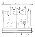
- the figure shows a monitoring unit according to the invention for optical Burst signals.
- Optical networks are increasingly based on asynchronous, packet-oriented networks such as ATM or Internet.
- burst-to-burst variations in signal level, clock frequency, and phase may occur.
- the monitoring unit takes these variations into account in the Q-factor measurement, which can be called a signal quality measurement, and performs a separate measurement for each burst.
- Each burst is synchronized and four measurement parameters are determined for each burst.
- the measurement parameters include a variable amplitude threshold, a fixed amplitude threshold, a variable phase position value, and a fixed phase position value.
- the eye diagram is evaluated at varying amplitude thresholds and sampling clock phases. This performs a pseudo-error measurement.
- the Q-factor and the current bit error rate are extrapolated and estimated from the measured values.
- bit error measurement of a data signal is then determined at the end of a transmission path through the network in a receiver taking into account decoding, eg Viterbi decoder, error correction, eg Forward Error Correction, etc., such a receiver is not part of the monitoring unit described here.
- the monitoring unit includes a detector for a Q-factor Measurement as a function of at least one variable and at least one fixed amplitude threshold and at least one variable and at least one fixed phase position value comprising a burst amplitude detector 9 for generating a fixed amplitude threshold for each burst, a burst clock recovery 10 to Generation of a fixed phase position value for each burst, a burst detector 11 for detecting the beginning of a burst, and a control logic 15 for generating a variable amplitude threshold and a variable phase position value for each burst.
- the monitoring unit is via an asymmetric optical coupler 1 connected to an optical line.
- the optical coupler 1 couples, for example, 10% of the Signal level of the received signals and passes them to a Optical / electrical converter 2 further; the remaining 90% will be for example, e.g. to an optical receiver for data evaluation forwarded.
- the received optical Burst signals converted into electrical signals and then to five Forwarded components.
- the forwarding takes place to a first Comparator 3, a second comparator 5, the burst amplitude detector 9, the burst clock recovery 10 and the burst detector 11th
- the comparator 3 the amplitudes of the electrical signal with compared to variable amplitude thresholds. For each burst, a new, variable amplitude threshold determined.
- the comparator 5 the amplitudes of the electrical signal with fixed Amplitude thresholds compared. For each burst, a new, fixed Amplitude threshold determined. The determination takes place in the amplitude detector 9, which selects an average, e.g. in the form of a solid Threshold.
- the comparator 3 is followed by a decision maker 4.
- the decision maker 4 the output signal supplied from the comparator 3 is sampled, and although depending on a variable phase. For each burst a new, variable phase position value determined. In the output signal of Thus, a variable amplitude threshold value and / or a variable phase position value.
- the comparator 5 is followed by a decision maker 6.
- the decision maker 6 the output signal supplied from the comparator 5 is sampled, and although depending on a solid phase. For each burst a new, determined fixed phase value.
- a fixed amplitude threshold and a fixed Phase angle value In the output signal of the decider thus flows per burst a fixed amplitude threshold and a fixed Phase angle value.
- the determination of the fixed phase position value takes place in the burst clock recovery 10, which is an average of a fixed Phase from the sampling clock selects.
- Gate 8 provides an error signal which is fed to a processing unit 16 becomes.
- the processing unit 16 is for example a corresponding programmed microprocessor. Your will be tax data for calculation supplied by extrapolation and estimation. From the error signal and the Control data 16, the processing unit 16 determines an estimate of the Q factor, which is output via an output and for monitoring and controlling the network, e.g. for the readjustment of Signal power on the transmission side or for reconfiguration of the network, if the signal quality of the relevant, monitored path determined Limits are below.
- the burst detector 11 is used to detect the beginning of a burst. To a start-of-burst detection is performed, which is a rough determination the start time of a current burst based on the detection of the Guard bands performs. This start-of-burst information becomes one the control logic 15 provided and the other one downstream burst synchronization logic 12, which is a fine Determining the start of the payload of the burst. This start-of-payload Information is provided to the control logic 15.
- Control logic 15 generated from the start-of-burst and the start-of-payload Information as well as further information that you receive from the Processing unit 16 receives and the information about the Eye diagram include a variable amplitude threshold and a variable phasing value for each burst.
- the control logic 15 is for example, as a suitably programmed microprocessor executed.
- Control logic 15 and processing unit 16 can also on a microprocessor, digital signal processor, FPGA or the like be executed together and have at least one data interface for the purpose of data exchange.
- the start-of-payload information is further an extraction unit 13 and a switch 14 and the control logic 15th
- the extraction unit 13 is used to extract the header and / or from Control information.
- the header information and / or the control information serves to selectively measure specific bursts and becomes the switch 14 forwarded to the control logic 15.
- Switch 14 is driven by the control logic 15, which selects which Variant of the measurement is to be performed, a general Q-factor Measurement for all bursts or a selective Q-factor measurement for special ones Bursts.
- the start-of-payload information is called Control signal forwarded to the gate 8, for the second variant, the headers Information.
- the variable amplitude thresholds and the variable phase position values in addition Depending on the header information determined.
- Extraction unit 13 and switch 14 are optional. Is not a Q-factor Measurement or estimation of special bursts provided, so they can by a direct connection of output burst synchronization logic 12 and Control input Gate 8 to be replaced.
Landscapes
- Engineering & Computer Science (AREA)
- Computer Networks & Wireless Communication (AREA)
- Signal Processing (AREA)
- Physics & Mathematics (AREA)
- Electromagnetism (AREA)
- Quality & Reliability (AREA)
- Optical Communication System (AREA)
- Data Exchanges In Wide-Area Networks (AREA)
Abstract
Description
Die eigentliche Bitfehlermessung eines Datensignals wird aber dann am Ende eines Übertragungspfades durch das Netz in einem Empfänger bestimmt unter Berücksichtigung von Dekodierung, z.B. Viterbi-Dekoder, Fehlerkorrektur, z.B. Forward Error Correction, etc, wobei ein solcher Empfänger nicht Teil der hier beschriebenen Überwachungseinheit ist.
Claims (5)
- Überwachungseinheit für Burst-Signale, beinhaltend einen Detektor für eine Q-Faktor Messung in Abhängigkeit mindestens eines variablen und mindestens eines festen Amplituden-Schwellwerts und mindestens eines variablen und mindestens eines festen Phasenlagen-Werts, der einen Burst-Amplitudendetektor (9) zur Generierung eines festen Amplituden-Schwellwertes für jedes in die Messung einzubeziehende Burst-Signal, eine Burst-Taktrückgewinnung (10) zur Generierung eines festen Phasenlagen-Wertes für jedes in die Messung einzubeziehende Burst-Signal, einen Burst-Detektor (11) zur Erkennung des jeweiligen Beginns von Burst-Signalen, und eine Steuerlogik (15) zur Generierung eines variablen Amplituden-Schwellwertes und eines variablen Phasenlagen-Wertes für jedes in die Messung einzubeziehende Burst-Signal beinhaltet.
- Überwachungseinheit nach Anspruch 1, dadurch gekennzeichnet, dass die Überwachungseinheit beinhaltet einen ersten Komparator (3) zum Vergleich von empfangenen Burst-Signalen mit zugehörigen generierten, variablen Amplituden-Schwellwerten, einen zweiten Komparator (5) zum Vergleich der empfangenen Burst-Signale mit zugehörigen generierten, festen Amplituden-Schwellwerten, einem dem ersten Komparator (3) nachgeschalteten ersten Entscheider (4) zur Weiterleitung der Ausgangssignale des ersten Komparators (3) in Abhängigkeit von den Burst-Signalen zugehörigen generierten, variablen Phasenlagen-Werten, einem dem zweiten Komparator (5) nachgeschalteten zweiten Entscheider (6) zur Weiterleitung der Ausgangssignale des zweiten Komparators (5) in Abhängigkeit von den Burst-Signalen zugehörigen generierten, festen Phasenlagen-Werten, und einem EXOR-Gatter (7) zur Verknüpfung der Ausgangssignale des ersten und zweiten Entscheiders (5, 6).
- Überwachungseinheit nach Anspruch 2, dadurch gekennzeichnet, dass die Überwachungseinheit beinhaltet eine dem Burst-Detektor (11) nachgeschaltete Burst-Synchronisationslogik (12) zur Bestimmung des jeweiligen Beginns der Payload von Burst-Signalen und einem dem EXOR-Gatter nachgeschalteten und von der Burst-Synchronisationslogik (12) gesteuerten Gate (8) zur Weiterleitung von Fehlersignalen zu einer Verarbeitungseinheit (16), die zur Schätzung eines Q-Faktors dient.
- Überwachungseinheit nach Anspruch 3, dadurch gekennzeichnet, dass die Überwachungseinheit beinhaltet eine der Burst-Synchronisationslogik (12) nachgeschalteten Extraktionseinheit (13) zur Extraktion von Headerund/oder von Steuerinformation zur selektiven Messung spezieller Burst-Signale und einem von der Steuerlogik (15) angesteuerten Schalter (14), der zwischen Extraktionseinheit (13), Burst-Synchronisationslogik (12) und Gate (8) geschaltet ist.
- Überwachungseinheit nach Anspruch 1, dadurch gekennzeichnet, dass die Überwachungseinheit zur Überwachung optischer Burst-Signale dient und einen Optisch/Elektrischen Umsetzer (2) zur Generierung von elektrischen Eingangssignalen für den Burst-Amplitudendetektor (9) die Burst-Taktrückgewinnung (10) und den Burst-Detektor (11) beinhaltet.
Priority Applications (3)
| Application Number | Priority Date | Filing Date | Title |
|---|---|---|---|
| EP01440225A EP1278314B1 (de) | 2001-07-17 | 2001-07-17 | Überwachungseinheit für optische Burst-Signale |
| DE50111853T DE50111853D1 (de) | 2001-07-17 | 2001-07-17 | Überwachungseinheit für optische Burst-Signale |
| US10/194,049 US7031616B2 (en) | 2001-07-17 | 2002-07-15 | Monitoring unit for optical burst mode signals |
Applications Claiming Priority (1)
| Application Number | Priority Date | Filing Date | Title |
|---|---|---|---|
| EP01440225A EP1278314B1 (de) | 2001-07-17 | 2001-07-17 | Überwachungseinheit für optische Burst-Signale |
Publications (2)
| Publication Number | Publication Date |
|---|---|
| EP1278314A1 true EP1278314A1 (de) | 2003-01-22 |
| EP1278314B1 EP1278314B1 (de) | 2007-01-10 |
Family
ID=8183260
Family Applications (1)
| Application Number | Title | Priority Date | Filing Date |
|---|---|---|---|
| EP01440225A Expired - Lifetime EP1278314B1 (de) | 2001-07-17 | 2001-07-17 | Überwachungseinheit für optische Burst-Signale |
Country Status (3)
| Country | Link |
|---|---|
| US (1) | US7031616B2 (de) |
| EP (1) | EP1278314B1 (de) |
| DE (1) | DE50111853D1 (de) |
Families Citing this family (60)
| Publication number | Priority date | Publication date | Assignee | Title |
|---|---|---|---|---|
| JP2003158493A (ja) * | 2001-11-21 | 2003-05-30 | Mitsubishi Electric Corp | 光遮断検出装置、光受信器、光送信器及び光遮断検出方法 |
| US7791290B2 (en) * | 2005-09-30 | 2010-09-07 | Virgin Islands Microsystems, Inc. | Ultra-small resonating charged particle beam modulator |
| US7586097B2 (en) * | 2006-01-05 | 2009-09-08 | Virgin Islands Microsystems, Inc. | Switching micro-resonant structures using at least one director |
| US20070034518A1 (en) * | 2005-08-15 | 2007-02-15 | Virgin Islands Microsystems, Inc. | Method of patterning ultra-small structures |
| US7626179B2 (en) * | 2005-09-30 | 2009-12-01 | Virgin Island Microsystems, Inc. | Electron beam induced resonance |
| US7573815B2 (en) * | 2005-03-04 | 2009-08-11 | Alcatel-Lucent Usa Inc. | Flow control and congestion management for random scheduling in time-domain wavelength interleaved networks |
| WO2007014243A2 (en) * | 2005-07-25 | 2007-02-01 | Mrv Communications, Inc. | Signal presence detector |
| US20070116465A1 (en) * | 2005-11-21 | 2007-05-24 | Tellabs Operations, Inc. | Systems and methods for dynamic alignment of data bursts conveyed over a passive optical net work |
| US7579609B2 (en) * | 2005-12-14 | 2009-08-25 | Virgin Islands Microsystems, Inc. | Coupling light of light emitting resonator to waveguide |
| US20070152781A1 (en) * | 2006-01-05 | 2007-07-05 | Virgin Islands Microsystems, Inc. | Switching micro-resonant structures by modulating a beam of charged particles |
| US7470920B2 (en) * | 2006-01-05 | 2008-12-30 | Virgin Islands Microsystems, Inc. | Resonant structure-based display |
| US7619373B2 (en) * | 2006-01-05 | 2009-11-17 | Virgin Islands Microsystems, Inc. | Selectable frequency light emitter |
| US20070200063A1 (en) * | 2006-02-28 | 2007-08-30 | Virgin Islands Microsystems, Inc. | Wafer-level testing of light-emitting resonant structures |
| US20070200071A1 (en) * | 2006-02-28 | 2007-08-30 | Virgin Islands Microsystems, Inc. | Coupling output from a micro resonator to a plasmon transmission line |
| US7605835B2 (en) * | 2006-02-28 | 2009-10-20 | Virgin Islands Microsystems, Inc. | Electro-photographic devices incorporating ultra-small resonant structures |
| US7443358B2 (en) * | 2006-02-28 | 2008-10-28 | Virgin Island Microsystems, Inc. | Integrated filter in antenna-based detector |
| US20070200646A1 (en) * | 2006-02-28 | 2007-08-30 | Virgin Island Microsystems, Inc. | Method for coupling out of a magnetic device |
| US7558490B2 (en) * | 2006-04-10 | 2009-07-07 | Virgin Islands Microsystems, Inc. | Resonant detector for optical signals |
| US7492868B2 (en) * | 2006-04-26 | 2009-02-17 | Virgin Islands Microsystems, Inc. | Source of x-rays |
| US20070252089A1 (en) * | 2006-04-26 | 2007-11-01 | Virgin Islands Microsystems, Inc. | Charged particle acceleration apparatus and method |
| US7876793B2 (en) * | 2006-04-26 | 2011-01-25 | Virgin Islands Microsystems, Inc. | Micro free electron laser (FEL) |
| US20070264023A1 (en) * | 2006-04-26 | 2007-11-15 | Virgin Islands Microsystems, Inc. | Free space interchip communications |
| US7583370B2 (en) * | 2006-05-05 | 2009-09-01 | Virgin Islands Microsystems, Inc. | Resonant structures and methods for encoding signals into surface plasmons |
| US7359589B2 (en) * | 2006-05-05 | 2008-04-15 | Virgin Islands Microsystems, Inc. | Coupling electromagnetic wave through microcircuit |
| US7718977B2 (en) * | 2006-05-05 | 2010-05-18 | Virgin Island Microsystems, Inc. | Stray charged particle removal device |
| US7746532B2 (en) * | 2006-05-05 | 2010-06-29 | Virgin Island Microsystems, Inc. | Electro-optical switching system and method |
| US7728702B2 (en) * | 2006-05-05 | 2010-06-01 | Virgin Islands Microsystems, Inc. | Shielding of integrated circuit package with high-permeability magnetic material |
| US7442940B2 (en) | 2006-05-05 | 2008-10-28 | Virgin Island Microsystems, Inc. | Focal plane array incorporating ultra-small resonant structures |
| US7557647B2 (en) * | 2006-05-05 | 2009-07-07 | Virgin Islands Microsystems, Inc. | Heterodyne receiver using resonant structures |
| US20070258492A1 (en) * | 2006-05-05 | 2007-11-08 | Virgin Islands Microsystems, Inc. | Light-emitting resonant structure driving raman laser |
| US8188431B2 (en) * | 2006-05-05 | 2012-05-29 | Jonathan Gorrell | Integration of vacuum microelectronic device with integrated circuit |
| US7342441B2 (en) | 2006-05-05 | 2008-03-11 | Virgin Islands Microsystems, Inc. | Heterodyne receiver array using resonant structures |
| US7710040B2 (en) * | 2006-05-05 | 2010-05-04 | Virgin Islands Microsystems, Inc. | Single layer construction for ultra small devices |
| US7436177B2 (en) | 2006-05-05 | 2008-10-14 | Virgin Islands Microsystems, Inc. | SEM test apparatus |
| US7723698B2 (en) * | 2006-05-05 | 2010-05-25 | Virgin Islands Microsystems, Inc. | Top metal layer shield for ultra-small resonant structures |
| US7728397B2 (en) * | 2006-05-05 | 2010-06-01 | Virgin Islands Microsystems, Inc. | Coupled nano-resonating energy emitting structures |
| US7476907B2 (en) * | 2006-05-05 | 2009-01-13 | Virgin Island Microsystems, Inc. | Plated multi-faceted reflector |
| US20070258675A1 (en) * | 2006-05-05 | 2007-11-08 | Virgin Islands Microsystems, Inc. | Multiplexed optical communication between chips on a multi-chip module |
| US7986113B2 (en) * | 2006-05-05 | 2011-07-26 | Virgin Islands Microsystems, Inc. | Selectable frequency light emitter |
| US7586167B2 (en) * | 2006-05-05 | 2009-09-08 | Virgin Islands Microsystems, Inc. | Detecting plasmons using a metallurgical junction |
| US7656094B2 (en) * | 2006-05-05 | 2010-02-02 | Virgin Islands Microsystems, Inc. | Electron accelerator for ultra-small resonant structures |
| US7554083B2 (en) * | 2006-05-05 | 2009-06-30 | Virgin Islands Microsystems, Inc. | Integration of electromagnetic detector on integrated chip |
| US20070272931A1 (en) * | 2006-05-05 | 2007-11-29 | Virgin Islands Microsystems, Inc. | Methods, devices and systems producing illumination and effects |
| US7741934B2 (en) * | 2006-05-05 | 2010-06-22 | Virgin Islands Microsystems, Inc. | Coupling a signal through a window |
| US7569836B2 (en) * | 2006-05-05 | 2009-08-04 | Virgin Islands Microsystems, Inc. | Transmission of data between microchips using a particle beam |
| US7443577B2 (en) * | 2006-05-05 | 2008-10-28 | Virgin Islands Microsystems, Inc. | Reflecting filtering cover |
| US7732786B2 (en) * | 2006-05-05 | 2010-06-08 | Virgin Islands Microsystems, Inc. | Coupling energy in a plasmon wave to an electron beam |
| US7573045B2 (en) * | 2006-05-15 | 2009-08-11 | Virgin Islands Microsystems, Inc. | Plasmon wave propagation devices and methods |
| US7679067B2 (en) * | 2006-05-26 | 2010-03-16 | Virgin Island Microsystems, Inc. | Receiver array using shared electron beam |
| US20070274365A1 (en) * | 2006-05-26 | 2007-11-29 | Virgin Islands Microsystems, Inc. | Periodically complex resonant structures |
| US7655934B2 (en) * | 2006-06-28 | 2010-02-02 | Virgin Island Microsystems, Inc. | Data on light bulb |
| US7450794B2 (en) * | 2006-09-19 | 2008-11-11 | Virgin Islands Microsystems, Inc. | Microcircuit using electromagnetic wave routing |
| US7560716B2 (en) * | 2006-09-22 | 2009-07-14 | Virgin Islands Microsystems, Inc. | Free electron oscillator |
| US8243869B2 (en) * | 2006-11-28 | 2012-08-14 | Broadlight Ltd. | Burst mode clock and data recovery circuit and method |
| US7659513B2 (en) * | 2006-12-20 | 2010-02-09 | Virgin Islands Microsystems, Inc. | Low terahertz source and detector |
| US7925156B2 (en) * | 2007-01-16 | 2011-04-12 | Broadlight, Ltd. | Apparatus and method for measuring the quality of burst signals and performing optical line diagnostics |
| US7990336B2 (en) * | 2007-06-19 | 2011-08-02 | Virgin Islands Microsystems, Inc. | Microwave coupled excitation of solid state resonant arrays |
| CN102088320B (zh) * | 2009-12-03 | 2013-10-30 | 建兴电子科技股份有限公司 | 超音波系统及其通讯方法 |
| US8693593B2 (en) * | 2010-12-30 | 2014-04-08 | Lsi Corporation | Methods and apparatus for automatic gain control using samples taken at desired sampling phase and target voltage level |
| CN103957066B (zh) * | 2014-05-21 | 2015-09-09 | 电子科技大学 | 一种基于非参数核函数的短时突发通信信号检测方法 |
Citations (4)
| Publication number | Priority date | Publication date | Assignee | Title |
|---|---|---|---|---|
| US5585954A (en) * | 1993-12-01 | 1996-12-17 | Kokusai Denshin Denwa Kabushiki Kaisha | Apparatus for measuring optical transmission characteristic |
| US5617237A (en) * | 1993-02-04 | 1997-04-01 | International Business Machines Corporation | Automated system, and corresponding method, for measuring transmitter extinction ratio of electro-optic modules |
| EP0999670A2 (de) * | 1998-11-02 | 2000-05-10 | Wandel & Goltermann GmbH & Co. Elektronische Messtechnik | Verfahren und Vorrichtung zur Messung der Signalgüte eines digitalen Nachrichtenübertragungssystems |
| WO2001020452A1 (en) * | 1999-09-17 | 2001-03-22 | Digital Lightwave, Inc. | Protocol and bit rate independent test system |
Family Cites Families (2)
| Publication number | Priority date | Publication date | Assignee | Title |
|---|---|---|---|---|
| US5040194A (en) * | 1986-07-15 | 1991-08-13 | Hayes Microcomputer Products, Inc. | Method and apparatus for providing for automatic gain control of incoming signals in a modem |
| US5365516A (en) * | 1991-08-16 | 1994-11-15 | Pinpoint Communications, Inc. | Communication system and method for determining the location of a transponder unit |
-
2001
- 2001-07-17 DE DE50111853T patent/DE50111853D1/de not_active Expired - Lifetime
- 2001-07-17 EP EP01440225A patent/EP1278314B1/de not_active Expired - Lifetime
-
2002
- 2002-07-15 US US10/194,049 patent/US7031616B2/en not_active Expired - Lifetime
Patent Citations (4)
| Publication number | Priority date | Publication date | Assignee | Title |
|---|---|---|---|---|
| US5617237A (en) * | 1993-02-04 | 1997-04-01 | International Business Machines Corporation | Automated system, and corresponding method, for measuring transmitter extinction ratio of electro-optic modules |
| US5585954A (en) * | 1993-12-01 | 1996-12-17 | Kokusai Denshin Denwa Kabushiki Kaisha | Apparatus for measuring optical transmission characteristic |
| EP0999670A2 (de) * | 1998-11-02 | 2000-05-10 | Wandel & Goltermann GmbH & Co. Elektronische Messtechnik | Verfahren und Vorrichtung zur Messung der Signalgüte eines digitalen Nachrichtenübertragungssystems |
| WO2001020452A1 (en) * | 1999-09-17 | 2001-03-22 | Digital Lightwave, Inc. | Protocol and bit rate independent test system |
Also Published As
| Publication number | Publication date |
|---|---|
| EP1278314B1 (de) | 2007-01-10 |
| US20030016412A1 (en) | 2003-01-23 |
| US7031616B2 (en) | 2006-04-18 |
| DE50111853D1 (de) | 2007-02-22 |
Similar Documents
| Publication | Publication Date | Title |
|---|---|---|
| EP1278314B1 (de) | Überwachungseinheit für optische Burst-Signale | |
| DE60129881T2 (de) | Optischer Transponder und automatisches Verfahren zur Identifizierung einer optischen Signalart | |
| DE69934852T2 (de) | IP-Paketkommunikationsvorrichtung | |
| DE60317588T2 (de) | Verfahren zur Ermittlung der peer-to-peer Servicequalität (QOS) | |
| DE60226190T2 (de) | Verfahren und Vorrichtung zur Messung und Bestimmung des optischen Signal-Rauschverhältnis in optischen Netzwerken | |
| EP1155531B1 (de) | System und verfahren zur messung der übertragungsdauer und der verluste in einem hochleistungs-telekommunikationsnetz | |
| DE102004014695A1 (de) | Takt- und Datenwiedergewinnungseinheit | |
| WO2002098035A1 (en) | Multi-protocol agile framer | |
| DE10219154A1 (de) | Verfahren zur Überwachung der Verfügbarkeit von Verbindungen in MPLS-Netzen | |
| DE69929881T2 (de) | Verfahren und gerät zum automatisierten zeitdomänenüberwachen in optischen netzen | |
| DE69533541T2 (de) | Phasendetektor und Taktrückgewinnungsanordnung in einem Empfänger für eine Multiplex- Funkanordnung | |
| JP4189000B2 (ja) | エンドポイントデータを使用したネットワークにおけるパケット損失率の測定 | |
| EP1502396A1 (de) | Verfahren zur unterstützung von ersatzschaltungen in mpls-netzen | |
| DE102006032545B3 (de) | Verfahren und Anordnungen zur Bestimmung des optischen Signal-Rausch-Verhältnisses für ein optisches Übertragungssystem | |
| CA1269137A (fr) | Procede et dispositif de calage en phase de trains numeriques synchrones | |
| EP0999670B1 (de) | Verfahren und Vorrichtung zur Messung der Signalgüte eines digitalen Nachrichtenübertragungssystems | |
| DE2921089C3 (de) | Verfahren zum Erzeugen eines Pseudofehlersignals in einer Fehlerrate-Überwachungseinheit und Schaltung zur Ausführung des Verfahrens | |
| EP1221221B1 (de) | Takt- und datenregenerator für unterschiedliche datenraten | |
| WO2004073244A1 (en) | Bit error rate monitoring method and device | |
| EP1159807A1 (de) | Gewinnung von taktsignalen zur abtastung von datensignalen unterschiedlicher datenraten mit hilfe eines phasenregelkreises | |
| DE69525391T2 (de) | Signalerkennungseinrichtung und Taktrückgewinnungseinrichtung welche diese Signalerkennungseinrichtung verwendet | |
| CA2372136C (en) | Technique for monitoring sonet signal | |
| DE102006045050B4 (de) | Verfahren und Vorrichtung zur Bestimmung der Latenzzeit eines digitalen Übertragungssystems, insbesondere eines digitalen optischen Übertragungssystems | |
| DE10010947A1 (de) | Takt- und Datenregenerator für unterschiedliche Datenraten | |
| Foroughi et al. | Detection of State Transitions in Network elements: On-box demo |
Legal Events
| Date | Code | Title | Description |
|---|---|---|---|
| PUAI | Public reference made under article 153(3) epc to a published international application that has entered the european phase |
Free format text: ORIGINAL CODE: 0009012 |
|
| 17P | Request for examination filed |
Effective date: 20021001 |
|
| AK | Designated contracting states |
Kind code of ref document: A1 Designated state(s): AT BE CH CY DE DK ES FI FR GB GR IE IT LI LU MC NL PT SE TR |
|
| AX | Request for extension of the european patent |
Free format text: AL;LT;LV;MK;RO;SI |
|
| AKX | Designation fees paid |
Designated state(s): AT BE CH CY DE DK ES FI FR GB GR IE IT LI LU MC NL PT SE TR |
|
| 17Q | First examination report despatched |
Effective date: 20031103 |
|
| GRAP | Despatch of communication of intention to grant a patent |
Free format text: ORIGINAL CODE: EPIDOSNIGR1 |
|
| GRAS | Grant fee paid |
Free format text: ORIGINAL CODE: EPIDOSNIGR3 |
|
| GRAA | (expected) grant |
Free format text: ORIGINAL CODE: 0009210 |
|
| AK | Designated contracting states |
Kind code of ref document: B1 Designated state(s): AT BE CH CY DE DK ES FI FR GB GR IE IT LI LU MC NL PT SE TR |
|
| PG25 | Lapsed in a contracting state [announced via postgrant information from national office to epo] |
Ref country code: DK Free format text: LAPSE BECAUSE OF FAILURE TO SUBMIT A TRANSLATION OF THE DESCRIPTION OR TO PAY THE FEE WITHIN THE PRESCRIBED TIME-LIMIT Effective date: 20070110 Ref country code: NL Free format text: LAPSE BECAUSE OF FAILURE TO SUBMIT A TRANSLATION OF THE DESCRIPTION OR TO PAY THE FEE WITHIN THE PRESCRIBED TIME-LIMIT Effective date: 20070110 Ref country code: FI Free format text: LAPSE BECAUSE OF FAILURE TO SUBMIT A TRANSLATION OF THE DESCRIPTION OR TO PAY THE FEE WITHIN THE PRESCRIBED TIME-LIMIT Effective date: 20070110 Ref country code: IE Free format text: LAPSE BECAUSE OF FAILURE TO SUBMIT A TRANSLATION OF THE DESCRIPTION OR TO PAY THE FEE WITHIN THE PRESCRIBED TIME-LIMIT Effective date: 20070110 |
|
| REG | Reference to a national code |
Ref country code: GB Ref legal event code: FG4D Free format text: NOT ENGLISH |
|
| RIN1 | Information on inventor provided before grant (corrected) |
Inventor name: BIGALK, UWE Inventor name: EILENBERGER, GERT, DR. |
|
| REG | Reference to a national code |
Ref country code: IE Ref legal event code: FG4D Free format text: LANGUAGE OF EP DOCUMENT: GERMAN |
|
| REF | Corresponds to: |
Ref document number: 50111853 Country of ref document: DE Date of ref document: 20070222 Kind code of ref document: P |
|
| GBT | Gb: translation of ep patent filed (gb section 77(6)(a)/1977) |
Effective date: 20070207 |
|
| RAP2 | Party data changed (patent owner data changed or rights of a patent transferred) |
Owner name: ALCATEL LUCENT |
|
| PG25 | Lapsed in a contracting state [announced via postgrant information from national office to epo] |
Ref country code: SE Free format text: LAPSE BECAUSE OF FAILURE TO SUBMIT A TRANSLATION OF THE DESCRIPTION OR TO PAY THE FEE WITHIN THE PRESCRIBED TIME-LIMIT Effective date: 20070410 |
|
| PG25 | Lapsed in a contracting state [announced via postgrant information from national office to epo] |
Ref country code: ES Free format text: LAPSE BECAUSE OF FAILURE TO SUBMIT A TRANSLATION OF THE DESCRIPTION OR TO PAY THE FEE WITHIN THE PRESCRIBED TIME-LIMIT Effective date: 20070421 |
|
| NLT2 | Nl: modifications (of names), taken from the european patent patent bulletin |
Owner name: ALCATEL LUCENT Effective date: 20070404 |
|
| PG25 | Lapsed in a contracting state [announced via postgrant information from national office to epo] |
Ref country code: PT Free format text: LAPSE BECAUSE OF FAILURE TO SUBMIT A TRANSLATION OF THE DESCRIPTION OR TO PAY THE FEE WITHIN THE PRESCRIBED TIME-LIMIT Effective date: 20070611 |
|
| NLV1 | Nl: lapsed or annulled due to failure to fulfill the requirements of art. 29p and 29m of the patents act | ||
| ET | Fr: translation filed | ||
| REG | Reference to a national code |
Ref country code: IE Ref legal event code: FD4D |
|
| PLBE | No opposition filed within time limit |
Free format text: ORIGINAL CODE: 0009261 |
|
| STAA | Information on the status of an ep patent application or granted ep patent |
Free format text: STATUS: NO OPPOSITION FILED WITHIN TIME LIMIT |
|
| 26N | No opposition filed |
Effective date: 20071011 |
|
| BERE | Be: lapsed |
Owner name: ALCATEL Effective date: 20070731 |
|
| REG | Reference to a national code |
Ref country code: CH Ref legal event code: PL |
|
| PG25 | Lapsed in a contracting state [announced via postgrant information from national office to epo] |
Ref country code: MC Free format text: LAPSE BECAUSE OF NON-PAYMENT OF DUE FEES Effective date: 20070731 Ref country code: LI Free format text: LAPSE BECAUSE OF NON-PAYMENT OF DUE FEES Effective date: 20070731 Ref country code: CH Free format text: LAPSE BECAUSE OF NON-PAYMENT OF DUE FEES Effective date: 20070731 Ref country code: GR Free format text: LAPSE BECAUSE OF FAILURE TO SUBMIT A TRANSLATION OF THE DESCRIPTION OR TO PAY THE FEE WITHIN THE PRESCRIBED TIME-LIMIT Effective date: 20070411 |
|
| PG25 | Lapsed in a contracting state [announced via postgrant information from national office to epo] |
Ref country code: BE Free format text: LAPSE BECAUSE OF NON-PAYMENT OF DUE FEES Effective date: 20070731 |
|
| PG25 | Lapsed in a contracting state [announced via postgrant information from national office to epo] |
Ref country code: AT Free format text: LAPSE BECAUSE OF NON-PAYMENT OF DUE FEES Effective date: 20070717 |
|
| PG25 | Lapsed in a contracting state [announced via postgrant information from national office to epo] |
Ref country code: CY Free format text: LAPSE BECAUSE OF FAILURE TO SUBMIT A TRANSLATION OF THE DESCRIPTION OR TO PAY THE FEE WITHIN THE PRESCRIBED TIME-LIMIT Effective date: 20070110 |
|
| PG25 | Lapsed in a contracting state [announced via postgrant information from national office to epo] |
Ref country code: LU Free format text: LAPSE BECAUSE OF NON-PAYMENT OF DUE FEES Effective date: 20070717 |
|
| PG25 | Lapsed in a contracting state [announced via postgrant information from national office to epo] |
Ref country code: TR Free format text: LAPSE BECAUSE OF FAILURE TO SUBMIT A TRANSLATION OF THE DESCRIPTION OR TO PAY THE FEE WITHIN THE PRESCRIBED TIME-LIMIT Effective date: 20070110 |
|
| REG | Reference to a national code |
Ref country code: FR Ref legal event code: GC Effective date: 20140717 |
|
| REG | Reference to a national code |
Ref country code: FR Ref legal event code: RG Effective date: 20141016 |
|
| REG | Reference to a national code |
Ref country code: FR Ref legal event code: PLFP Year of fee payment: 15 |
|
| REG | Reference to a national code |
Ref country code: FR Ref legal event code: CA Effective date: 20150521 |
|
| REG | Reference to a national code |
Ref country code: FR Ref legal event code: CA Effective date: 20150521 |
|
| REG | Reference to a national code |
Ref country code: FR Ref legal event code: PLFP Year of fee payment: 16 |
|
| REG | Reference to a national code |
Ref country code: FR Ref legal event code: PLFP Year of fee payment: 17 |
|
| PGFP | Annual fee paid to national office [announced via postgrant information from national office to epo] |
Ref country code: IT Payment date: 20170728 Year of fee payment: 17 |
|
| REG | Reference to a national code |
Ref country code: FR Ref legal event code: PLFP Year of fee payment: 18 |
|
| REG | Reference to a national code |
Ref country code: DE Ref legal event code: R081 Ref document number: 50111853 Country of ref document: DE Owner name: PROVENANCE ASSET GROUP LLC, PITTSFORD, US Free format text: FORMER OWNER: ALCATEL LUCENT, PARIS, FR |
|
| PG25 | Lapsed in a contracting state [announced via postgrant information from national office to epo] |
Ref country code: IT Free format text: LAPSE BECAUSE OF NON-PAYMENT OF DUE FEES Effective date: 20180717 |
|
| REG | Reference to a national code |
Ref country code: GB Ref legal event code: 732E Free format text: REGISTERED BETWEEN 20190829 AND 20190904 |
|
| PGFP | Annual fee paid to national office [announced via postgrant information from national office to epo] |
Ref country code: FR Payment date: 20200629 Year of fee payment: 20 |
|
| PGFP | Annual fee paid to national office [announced via postgrant information from national office to epo] |
Ref country code: GB Payment date: 20200609 Year of fee payment: 20 |
|
| PGFP | Annual fee paid to national office [announced via postgrant information from national office to epo] |
Ref country code: DE Payment date: 20200601 Year of fee payment: 20 |
|
| REG | Reference to a national code |
Ref country code: DE Ref legal event code: R071 Ref document number: 50111853 Country of ref document: DE |
|
| REG | Reference to a national code |
Ref country code: GB Ref legal event code: PE20 Expiry date: 20210716 |
|
| PG25 | Lapsed in a contracting state [announced via postgrant information from national office to epo] |
Ref country code: GB Free format text: LAPSE BECAUSE OF EXPIRATION OF PROTECTION Effective date: 20210716 |