EP1278287A1 - Capacitor unit with electric double layer capacitors, control method and control apparatus for the same, and accumulator system for motor vehicles - Google Patents
Capacitor unit with electric double layer capacitors, control method and control apparatus for the same, and accumulator system for motor vehicles Download PDFInfo
- Publication number
- EP1278287A1 EP1278287A1 EP02291790A EP02291790A EP1278287A1 EP 1278287 A1 EP1278287 A1 EP 1278287A1 EP 02291790 A EP02291790 A EP 02291790A EP 02291790 A EP02291790 A EP 02291790A EP 1278287 A1 EP1278287 A1 EP 1278287A1
- Authority
- EP
- European Patent Office
- Prior art keywords
- double layer
- electric double
- state
- capacitor
- charge
- Prior art date
- Legal status (The legal status is an assumption and is not a legal conclusion. Google has not performed a legal analysis and makes no representation as to the accuracy of the status listed.)
- Ceased
Links
Images



Classifications
-
- H—ELECTRICITY
- H02—GENERATION; CONVERSION OR DISTRIBUTION OF ELECTRIC POWER
- H02J—ELECTRIC POWER NETWORKS; CIRCUIT ARRANGEMENTS OR SYSTEMS FOR SUPPLYING OR DISTRIBUTING ELECTRIC POWER; SYSTEMS FOR STORING ELECTRIC ENERGY
- H02J7/00—Circuit arrangements for charging or discharging batteries or for supplying loads from batteries
- H02J7/50—Circuit arrangements for charging or discharging batteries or for supplying loads from batteries acting upon multiple batteries simultaneously or sequentially
- H02J7/52—Circuit arrangements for charging or discharging batteries or for supplying loads from batteries acting upon multiple batteries simultaneously or sequentially for charge balancing, e.g. equalisation of charge between batteries
- H02J7/54—Passive balancing, e.g. using resistors or parallel MOSFETs
-
- H—ELECTRICITY
- H02—GENERATION; CONVERSION OR DISTRIBUTION OF ELECTRIC POWER
- H02J—ELECTRIC POWER NETWORKS; CIRCUIT ARRANGEMENTS OR SYSTEMS FOR SUPPLYING OR DISTRIBUTING ELECTRIC POWER; SYSTEMS FOR STORING ELECTRIC ENERGY
- H02J7/00—Circuit arrangements for charging or discharging batteries or for supplying loads from batteries
- H02J7/34—Parallel operation in networks using both storage and other DC sources, e.g. providing buffering
- H02J7/345—Parallel operation in networks using both storage and other DC sources, e.g. providing buffering using capacitors as storage or buffering devices
-
- Y—GENERAL TAGGING OF NEW TECHNOLOGICAL DEVELOPMENTS; GENERAL TAGGING OF CROSS-SECTIONAL TECHNOLOGIES SPANNING OVER SEVERAL SECTIONS OF THE IPC; TECHNICAL SUBJECTS COVERED BY FORMER USPC CROSS-REFERENCE ART COLLECTIONS [XRACs] AND DIGESTS
- Y02—TECHNOLOGIES OR APPLICATIONS FOR MITIGATION OR ADAPTATION AGAINST CLIMATE CHANGE
- Y02T—CLIMATE CHANGE MITIGATION TECHNOLOGIES RELATED TO TRANSPORTATION
- Y02T10/00—Road transport of goods or passengers
- Y02T10/60—Other road transportation technologies with climate change mitigation effect
- Y02T10/70—Energy storage systems for electromobility, e.g. batteries
Definitions
- This invention relates to controlling of charging and discharging of a chargeable and dischargeable capacitor unit with plural electric double layer capacitors connected in series and more particularly to controlling of charging and discharging of electric double layer capacitors to be a power source used for the purpose of improving energy efficiency of vehicles including a 12V vehicle, a 42V vehicle, an electric vehicle, and a hybrid powered vehicle and a power storage such as road leveling.
- the 12V vehicle employs a lead battery while the hybrid powered vehicle employs a nickel metal hydride battery. Also, the lead battery and the nickel-cadmium battery have been used as the power storage.
- a conventional power storage device including the lead storage battery, nickel-cadmium battery, and nickel metal hydride battery is a chemical cell utilizing chemical reaction. Accordingly, the conventional power storage devices are not suitable for high output because reaction speed relative to charging and discharging is extremely slow relative to electronic conduction and has shorter lifetime comparing with other electric and electronic components because reaction reversibility is apt to be degraded in connection with charging and discharging cycle.
- An object of this invention is to improve a capacitor unit with plural double layer capacitors to eliminate irregularity in a state of charge of the respective double layer capacitor in the capacitor unit.
- Another object of this invention is to downsize a discharging circuit for electric double layer capacitors.
- this invention has an advantage of its suitability in high output and its longer lifetime because capacitors utilizing electric double layers only absorb and desorb relative to charging and discharging the capacitor, thereby proving very fast reaction speed and maintaining its theoretical reversibility.
- a capacitor unit composed of plural electric double layer capacitors connected in series causes irregularity in the state of charge among the electric double layer capacitors and overcharging and degradation of the electric double layer capacitors. Accordingly, another object of this invention is to equalize the state of charge of plural electric double layer capacitors connected in series.
- this invention provides a chargeable and dischargeable capacitor unit with plural electronic double layer capacitors connected in series is characterized in that electric double layer capacitors in a higher state of charge is subject to discharge so that a state of charging of the respective electric double layer capacitor may become approximately equal to each other.
- This invention further provides the capacitor unit with plural electric double layer capacitors connected in series as above, wherein a state of charge of an electric double layer capacitor is calculated by the voltage of the electric double layer capacitor.
- This invention still further provides a capacitor unit with plural electric double layer capacitors connected in series as above, wherein plural series circuits, each comprising an adjusting resistance and an electric switch, are parallelly connected relative to the respective electric double layer capacitor; and when an electric switch is turned on, an electric current running through the adjusting resistance is to be within an allowable range for the electric double layer capacitor.
- This invention still further provides the capacitor unit with plural electric double layer capacitors connected in series as above, wherein an adjusting resistance being connected parallel to the respective electric double layer capacitor and adjusting a state of charge of the respective electric double layer capacitor is to be larger than a value dividing a rated voltage or a withstand voltage of the electric double layer capacitor by an upper limit current of wiring materials and parts.
- This invention still further is the capacitor unit with plural electric double layer capacitors connected in series as above, wherein if a difference between a state of charging of an electric double layer capacitor in a highest state of charge and an average state of charge of the rest of electric double layer capacitors becomes an upper limit value or more, the electric double layer capacitor in the highest state of charge is subject to discharge and if the difference becomes a lower limit value or less, discharging of the electric double layer capacitor in the highest state of charge is suspended.
- This invention still further is the capacitor unit with plural electric double layer capacitors connected in series as above, wherein if a difference between a state of charging of an electric double layer capacitor in a highest state of charge and a state of charging of an electric double layer capacitor in a lowest state of charge becomes an upper limit value or more, the electric double layer capacitor in the highest state of charge is subject to discharge and if the difference becomes a lower limit value or less, discharging of the electric double layer capacitor in the highest state of charge is suspended.
- This invention further provides a control method of a chargeable and dischargeable capacitor unit with plural electronic double layer capacitors connected in series is characterized in that electric double layer capacitors in a higher state of charge is subject to discharge so that a state of charging of the respective electric double layer capacitor may become approximately equal to each other.
- This invention still further provides a capacitor unit control apparatus, comprising a chargeable and dischargeable capacitor unit with plural electric double layer capacitors connected in series; a voltmeter measuring the voltage of the respective electric double layer capacitor; a series circuit having an adjusting resistance and an electric switch connected parallel to the respective electric double layer capacitor; and an electric switch control device turning the electric switch on to discharge the electric double layer capacitor, wherein an electric switch for an electric double layer capacitor in a higher state of charge is turned on to discharge the same so that a state of charging of the respective electric double layer capacitor may become approximately equal to each other.
- This invention yet further is a chargeable and dischargeable capacitor system with plural electronic double layer capacitors connected in series, wherein an electric double layer capacitor in a higher state of charge is subject to discharge so that a state of charging of the respective electric double layer capacitor may become approximately equal to each other.
- a capacitor unit of this invention is characterized in that plural electric double layer capacitor calls or plural capacitor modules, each having 2 or more parallely connected capacitor cells, are connected in series, wherein adjusting reisistances R i ( ⁇ ) and electric switches SW i are connected in parallel to the respective electric double layer capacitor C i as shown in FIG. 1.
- the adjusting resistance R i is to be V i /I o ( ⁇ ) or more if the rated voltage or the withstand voltage of the electric double layer capacitor C i connected in parallel is V i (V) and a current value durable for electric switch SW i connected with adjusting resistances R i ( ⁇ ) in series or a copper wire is I o (A).
- V the rated voltage or the withstand voltage of the electric double layer capacitor C i connected in parallel
- I o (A) a current value durable for electric switch SW i connected with adjusting resistances R i ( ⁇ ) in series or a copper wire
- a capacitor unit control apparatus 2 is designed to avoid irregularity in the respective state of charge of plural electric double layer capacitors 11 constituting a capacitor unit 1 and to prevent overcharging of the capacitor unit 1.
- the capacitor unit control device 2 measures voltage of the respective electric double layer capacitor 11 and controls discharging of the electric double layer capacitor 11 with higher state of charge than other electric double layer capacitors 11 by utilizing a switch control device 21.
- the capacitor unit 1 comprises the electric double layer capacitors 11 connected in series.
- the electric double layer capacitor 11 means an electric double layer capacitor cell or a capacitor module of plural electric double layer capacitor cells arranged in parallel.
- ion conductive materials are arranged between a pair of electrode structures, and an electrical double layer is formed between a material with high surface area in the electrode structure and an electrolyte of the ion conductive material.
- a large surface area material is a powdery large surface area material pulling many ions thereon, and it is preferable to use activated carbon, which can be obtained from carbon material by steam activation method or by melted KOH activation process.
- activated carbon which can be obtained from carbon material by steam activation method or by melted KOH activation process.
- palmae shell type activated carbon types, phenol type activated carbon, petroleum coke type activated carbon, and polyacene may be used as activated carbon. These materials may be used alone or in a combination of two types or more. Among those, because of a large electrostatic capacity, phenol type activated carbon, petroleum cokes type activated carbon, and polyacene are preferable
- the state of charge of the electric double layer capacitor 11 means a condition of an accumulated amount of electric charge, which for example may be measured by a voltmeter 22 and an ammeter. If the voltmeter 22 is used, the voltage of the electrical double layer capacitor may be measured to determine the state of charge. For example, the voltmeter 22 may be connected between the electric double layer capacitors. The measured value is transmitted to the switch control device 21 via a voltage measuring wire 23.
- the adjusting resistance 12 means resistance adjusting the state of charge of the electric double layer capacitor 11, wherein electricity charged in the electric double layer capacitor 11 may be discharged via the resistance.
- the adjusting resistance 12 may parallelly be connected with the electric double layer capacitor 11.
- the adjusting resistance R i is to be V i /I o ( ⁇ ) or more if the rated voltage or the withstand voltage of the electric double layer capacitor C i connected in parallel is V i (V) and a current value durable for electric switch SW i connected with adjusting resistances R i ( ⁇ )in series or a copper wire is I o (A). As such, downsizing of a section positioning the adjusting resistance 12 and the electric switch 13 becomes possible.
- the electric switch 13 is a device to switch the electric double layer capacitor 11 to discharge electricity charged therein via the adjusting resistance 12, which for example is connected with the adjusting resistance 12 in series.
- the switch control device 21 controls the electric switch 13 to be turned on or off via the switch control wire 24.
- a relay device and a thyristor may be used as the electric switch 13.
- the switch control device 21 measures the voltage V l -V n of the respective electric double layer capacitor 11 to select the respective electric double layer capacitor 11 in a higher state of charge; turns on the electric switch 13 of the electric double layer capacitor 11 in the higher state of charge so as to discharge the accumulated electric charge; and upon the state of charging of the respective electric double layer capacitor becoming approximately equal to other electric double layer capacitors, turns off the electric switch so as to control the state of charge of the electric double layer capacitors 11.
- the switch control device 21 regardless of the state of charge, pause, and discharge of the respective electric double layer capacitor 11, discharges only the electric double layer capacitor connected in parallel to the adjusting resistance R i by turning on and off the electric switch 21 of the adjusting resistance R i , thereby enabling to lower the state of charge.
- the capacitor unit 1 may be composed of 17 electric double layer capacitor cells 11 with rated electrostatic capacity of 4,000F and rated voltage of 2.47V, all connected in series.
- a circuit in FIG. 2 may be designed such that the resistance of 2.47 ⁇ and the electric switch 13 are connected in parallel with the respective electric double layer capacitor 11 utilizing wiring materials capable of flowing electric current 1A.
- the switch control device 21 has a voltage detecting and measuring function and may turn the electric switch 13 on and off to control the same.
- a vehicle capacitor system is an applicable system for the capacitor unit 1.
- the vehicle capacitor unit is a charging system for a 12V vehicle, a 42V vehicle, an electric vehicle, or a hybrid powered vehicle, which comprises a capacitor unit 1 made in combination of electrical double layer capacitor cells, at least capable of being charged by an alternator A, recharged after braking by a charger B, discharged by an engine starter D, or charged and discharged by any other load E. That is, the capacitor unit 1 may employ one type of charging and discharging means or plural types of charging and discharging means. This construction satisfies necessary conditions for a power supply of a vehicle, for example conditions of voltage and electric current relative to the engine start and other electric devices and conditions of charging by an alternator and recharging by braking.
- ⁇ SOC i (%) SOC k (%) - ( ⁇ SOC k - SOC k ) / (n - 1) (which is shown as S13).
- the electric switch SW k is turned on (and the rest of switches are turned off) (as shown in S15).
- Voltage V i of the respective electric double layer capacitor C i and the state of charge SOC i are measured without determining whether the state of charge SOC k of the electric double layer capacitors C k is the highest state; and ⁇ SOC i relative to "k" is determined even if the electric double layer capacitor C k is discharged and the state of charge SOC k becomes non-highest state (as shown in S16).
- the electric switch SW k is turned on (and the rest of switches SW i are turned off) (as shown in S15).
- Voltage V i of the respective electric double layer capacitor C i and the state of charge SOC i and ⁇ SOC i are measured without determining whether the state of charge SOC k of the electric double layer capacitors C k is the highest state (as shown in S16).
- the irregularity ⁇ SOC i (%) determined relative to "k" is a threshold value B (%), which is lower than the threshold value A, or lower (as shown in S17), the electric switch SW k is turned off (as shown in S18) and the process goes back to an initial step in the flowchart of FIG. 4 to repeat detection and control.
- this invention renders the advantages to improve a capacitor unit with plural double layer capacitors to eliminate irregularity in a state of charge of the respective double layer capacitor in the capacitor unit and also to downsize a discharging circuit for electric double layer capacitors.
Landscapes
- Engineering & Computer Science (AREA)
- Power Engineering (AREA)
- Charge And Discharge Circuits For Batteries Or The Like (AREA)
- Electric Propulsion And Braking For Vehicles (AREA)
Abstract
Description
- This invention relates to controlling of charging and discharging of a chargeable and dischargeable capacitor unit with plural electric double layer capacitors connected in series and more particularly to controlling of charging and discharging of electric double layer capacitors to be a power source used for the purpose of improving energy efficiency of vehicles including a 12V vehicle, a 42V vehicle, an electric vehicle, and a hybrid powered vehicle and a power storage such as road leveling.
- As a conventional capacitor device for a vehicle, the 12V vehicle employs a lead battery while the hybrid powered vehicle employs a nickel metal hydride battery. Also, the lead battery and the nickel-cadmium battery have been used as the power storage.
- A conventional power storage device including the lead storage battery, nickel-cadmium battery, and nickel metal hydride battery is a chemical cell utilizing chemical reaction. Accordingly, the conventional power storage devices are not suitable for high output because reaction speed relative to charging and discharging is extremely slow relative to electronic conduction and has shorter lifetime comparing with other electric and electronic components because reaction reversibility is apt to be degraded in connection with charging and discharging cycle.
- An object of this invention is to improve a capacitor unit with plural double layer capacitors to eliminate irregularity in a state of charge of the respective double layer capacitor in the capacitor unit.
- Another object of this invention is to downsize a discharging circuit for electric double layer capacitors.
- More concretely, this invention has an advantage of its suitability in high output and its longer lifetime because capacitors utilizing electric double layers only absorb and desorb relative to charging and discharging the capacitor, thereby proving very fast reaction speed and maintaining its theoretical reversibility. However, a capacitor unit composed of plural electric double layer capacitors connected in series causes irregularity in the state of charge among the electric double layer capacitors and overcharging and degradation of the electric double layer capacitors. Accordingly, another object of this invention is to equalize the state of charge of plural electric double layer capacitors connected in series.
- In order to resolve the above-problems, this invention provides a chargeable and dischargeable capacitor unit with plural electronic double layer capacitors connected in series is characterized in that electric double layer capacitors in a higher state of charge is subject to discharge so that a state of charging of the respective electric double layer capacitor may become approximately equal to each other.
- This invention further provides the capacitor unit with plural electric double layer capacitors connected in series as above, wherein a state of charge of an electric double layer capacitor is calculated by the voltage of the electric double layer capacitor.
- This invention still further provides a capacitor unit with plural electric double layer capacitors connected in series as above, wherein plural series circuits, each comprising an adjusting resistance and an electric switch, are parallelly connected relative to the respective electric double layer capacitor; and when an electric switch is turned on, an electric current running through the adjusting resistance is to be within an allowable range for the electric double layer capacitor.
- This invention still further provides the capacitor unit with plural electric double layer capacitors connected in series as above, wherein an adjusting resistance being connected parallel to the respective electric double layer capacitor and adjusting a state of charge of the respective electric double layer capacitor is to be larger than a value dividing a rated voltage or a withstand voltage of the electric double layer capacitor by an upper limit current of wiring materials and parts.
- This invention still further is the capacitor unit with plural electric double layer capacitors connected in series as above, wherein if a difference between a state of charging of an electric double layer capacitor in a highest state of charge and an average state of charge of the rest of electric double layer capacitors becomes an upper limit value or more, the electric double layer capacitor in the highest state of charge is subject to discharge and if the difference becomes a lower limit value or less, discharging of the electric double layer capacitor in the highest state of charge is suspended.
- This invention still further is the capacitor unit with plural electric double layer capacitors connected in series as above, wherein if a difference between a state of charging of an electric double layer capacitor in a highest state of charge and a state of charging of an electric double layer capacitor in a lowest state of charge becomes an upper limit value or more, the electric double layer capacitor in the highest state of charge is subject to discharge and if the difference becomes a lower limit value or less, discharging of the electric double layer capacitor in the highest state of charge is suspended.
- This invention further provides a control method of a chargeable and dischargeable capacitor unit with plural electronic double layer capacitors connected in series is characterized in that electric double layer capacitors in a higher state of charge is subject to discharge so that a state of charging of the respective electric double layer capacitor may become approximately equal to each other.
- This invention still further provides a capacitor unit control apparatus, comprising a chargeable and dischargeable capacitor unit with plural electric double layer capacitors connected in series; a voltmeter measuring the voltage of the respective electric double layer capacitor; a series circuit having an adjusting resistance and an electric switch connected parallel to the respective electric double layer capacitor; and an electric switch control device turning the electric switch on to discharge the electric double layer capacitor, wherein an electric switch for an electric double layer capacitor in a higher state of charge is turned on to discharge the same so that a state of charging of the respective electric double layer capacitor may become approximately equal to each other.
- This invention yet further is a chargeable and dischargeable capacitor system with plural electronic double layer capacitors connected in series, wherein an electric double layer capacitor in a higher state of charge is subject to discharge so that a state of charging of the respective electric double layer capacitor may become approximately equal to each other.
- More concretely, a capacitor unit of this invention is characterized in that plural electric double layer capacitor calls or plural capacitor modules, each having 2 or more parallely connected capacitor cells, are connected in series, wherein adjusting reisistances Ri(Ω) and electric switches SWi are connected in parallel to the respective electric double layer capacitor Ci as shown in FIG. 1.
- At that time, the adjusting resistance Ri is to be Vi/Io (Ω) or more if the rated voltage or the withstand voltage of the electric double layer capacitor Ci connected in parallel is Vi(V) and a current value durable for electric switch SWi connected with adjusting resistances Ri (Ω) in series or a copper wire is Io(A). As such, downsizing of a section positioning the adjusting resistance and the electric switch becomes possible.
- In this system, regardless of the state of charge, pause, and discharge, only the electric double layer capacitor connected in parallel to the adjusting resistance is discharged by turning the electric switch of the adjusting resistance Ri on and off.
- The above and other objects and the attendant advantages of the present invention will become readily apparent by reference to the following detailed description when considered in conjunction with the accompanying drawings wherein:
- FIG. 1 is a circuit drawing of a capacitor system for a vehicle with a capacitor unit with plural connected electric double layer capacitors;
- FIG. 2 is a drawing to explain a capacitor unit control device;
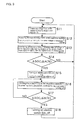
- FIG. 3 is a flowchart of a process in reducing irregularity of a state of charge of the respective electric double layer capacitor and;
- FIG. 4 is another flowchart of a process in reducing irregularity of a state of charge of the respective electric double layer capacitor.
-
- The embodiments of the invention are next described while referring to the accompanying drawings.
- A capacitor
unit control apparatus 2 is designed to avoid irregularity in the respective state of charge of plural electricdouble layer capacitors 11 constituting acapacitor unit 1 and to prevent overcharging of thecapacitor unit 1. For that purpose, the capacitorunit control device 2 measures voltage of the respective electricdouble layer capacitor 11 and controls discharging of the electricdouble layer capacitor 11 with higher state of charge than other electricdouble layer capacitors 11 by utilizing aswitch control device 21. - The
capacitor unit 1 comprises the electricdouble layer capacitors 11 connected in series. The electricdouble layer capacitor 11 means an electric double layer capacitor cell or a capacitor module of plural electric double layer capacitor cells arranged in parallel. - In the electrical double layer capacitor cell, ion conductive materials are arranged between a pair of electrode structures, and an electrical double layer is formed between a material with high surface area in the electrode structure and an electrolyte of the ion conductive material. A large surface area material is a powdery large surface area material pulling many ions thereon, and it is preferable to use activated carbon, which can be obtained from carbon material by steam activation method or by melted KOH activation process. For example palmae shell type activated carbon types, phenol type activated carbon, petroleum coke type activated carbon, and polyacene may be used as activated carbon. These materials may be used alone or in a combination of two types or more. Among those, because of a large electrostatic capacity, phenol type activated carbon, petroleum cokes type activated carbon, and polyacene are preferable
- The state of charge of the electric
double layer capacitor 11 means a condition of an accumulated amount of electric charge, which for example may be measured by avoltmeter 22 and an ammeter. If thevoltmeter 22 is used, the voltage of the electrical double layer capacitor may be measured to determine the state of charge. For example, thevoltmeter 22 may be connected between the electric double layer capacitors. The measured value is transmitted to theswitch control device 21 via avoltage measuring wire 23. - The adjusting
resistance 12 means resistance adjusting the state of charge of the electricdouble layer capacitor 11, wherein electricity charged in the electricdouble layer capacitor 11 may be discharged via the resistance. For example, the adjustingresistance 12 may parallelly be connected with the electricdouble layer capacitor 11. The adjusting resistance Ri is to be Vi/Io (Ω) or more if the rated voltage or the withstand voltage of the electric double layer capacitor Ci connected in parallel is Vi(V) and a current value durable for electric switch SWi connected with adjusting resistances Ri (Ω)in series or a copper wire is Io(A). As such, downsizing of a section positioning the adjustingresistance 12 and theelectric switch 13 becomes possible. - The
electric switch 13 is a device to switch the electricdouble layer capacitor 11 to discharge electricity charged therein via the adjustingresistance 12, which for example is connected with the adjustingresistance 12 in series. Theswitch control device 21 controls theelectric switch 13 to be turned on or off via theswitch control wire 24. A relay device and a thyristor may be used as theelectric switch 13. - The
switch control device 21 measures the voltage Vl-Vn of the respective electricdouble layer capacitor 11 to select the respective electricdouble layer capacitor 11 in a higher state of charge; turns on theelectric switch 13 of the electricdouble layer capacitor 11 in the higher state of charge so as to discharge the accumulated electric charge; and upon the state of charging of the respective electric double layer capacitor becoming approximately equal to other electric double layer capacitors, turns off the electric switch so as to control the state of charge of the electricdouble layer capacitors 11. - The
switch control device 21, regardless of the state of charge, pause, and discharge of the respective electricdouble layer capacitor 11, discharges only the electric double layer capacitor connected in parallel to the adjusting resistance Ri by turning on and off theelectric switch 21 of the adjusting resistance Ri, thereby enabling to lower the state of charge. - For example, the
capacitor unit 1 may be composed of 17 electric doublelayer capacitor cells 11 with rated electrostatic capacity of 4,000F and rated voltage of 2.47V, all connected in series. A circuit in FIG. 2 may be designed such that the resistance of 2.47Ω and theelectric switch 13 are connected in parallel with the respective electricdouble layer capacitor 11 utilizing wiring materials capable of flowing electric current 1A. Theswitch control device 21 has a voltage detecting and measuring function and may turn theelectric switch 13 on and off to control the same. - A vehicle capacitor system is an applicable system for the
capacitor unit 1. The vehicle capacitor unit is a charging system for a 12V vehicle, a 42V vehicle, an electric vehicle, or a hybrid powered vehicle, which comprises acapacitor unit 1 made in combination of electrical double layer capacitor cells, at least capable of being charged by an alternator A, recharged after braking by a charger B, discharged by an engine starter D, or charged and discharged by any other load E. That is, thecapacitor unit 1 may employ one type of charging and discharging means or plural types of charging and discharging means. This construction satisfies necessary conditions for a power supply of a vehicle, for example conditions of voltage and electric current relative to the engine start and other electric devices and conditions of charging by an alternator and recharging by braking. - In the following section, a procedure of equalizing the state of charge of the electric double layer capacitors is disclosed.
- According to a flowchart shown in FIG. 3, voltage V of the respective electric double layer capacitor Ci is measured while charging and discharging (which is shown as S11); the state of charge SOCi (%) of the respective capacitor Ci is measured by the rated voltage or withstand voltage Vo(V) of the electric
double layer capacitor 11, i.e., SOCi (%) = Vi(V)/Vo(V) x 100 (which is shown as S12). Accordingly, the state of charge of the respective electric double layer capacitor Ci is measured. - Then, "i" with a highest state of charge within SOCi, is determined and is expressed as Ck. Irregularity ΔSOCi (%) of Ci, i.e., a difference between the state of charge SOCk of the electric double layer capacitor cell Ck with the highest state of charge and average state of charge of other capacitor cells, is determined by ΔSOCi (%) = SOCk (%) - (ΣSOCk - SOCk) / (n - 1) (which is shown as S13).
- If the irregularity ΔSOCi (%) is a threshold value A (%) or more, for example 30% or more (as shown in S14), the electric switch SWk is turned on (and the rest of switches are turned off) (as shown in S15). Voltage Vi of the respective electric double layer capacitor Ci and the state of charge SOCi, are measured without determining whether the state of charge SOCk of the electric double layer capacitors Ck is the highest state; and ΔSOCi relative to "k" is determined even if the electric double layer capacitor Ck is discharged and the state of charge SOCk becomes non-highest state (as shown in S16). If the irregularity ΔSOCi (%) is a threshold value B (%) which is lower than A (%) or lower (as shown in S17), the electric switch SWk is turned off (as shown in S18) and the process goes back to an initial step in the flowchart of FIG. 3 to repeat detection and control.
- According to a control flowchart in FIG. 4, "i" with a highest state of charge within SOCi, is determined and is expressed as Ck; and "i" with a lowest state of charge within SOCi is determined and is expressed as Cl (as shown in S21). Same reference numbers in the identical steps of the flowchart of FIG. 3 are placed on a flowchart of FIG. 4. Irregularity ΔSOCi (%) of Ci, i.e., a difference between the highest state of charge SOCk and the lowest state of charge SOCl (%), is determined by ΔSOCi (%) = SOCk (%) - SOCl (which is shown as S21).
- If the irregularity ΔSOCi (%) is a threshold value A (%) or more, for example 30% or more (as shown in S14), the electric switch SWk is turned on (and the rest of switches SWi are turned off) (as shown in S15). Voltage Vi of the respective electric double layer capacitor Ci and the state of charge SOCi and ΔSOCi are measured without determining whether the state of charge SOCk of the electric double layer capacitors Ck is the highest state (as shown in S16). Even if the electric double layer capacitor Ck is discharged and the state of charge SOCk becomes non-highest state, the irregularity ΔSOCi (%) determined relative to "k" is a threshold value B (%), which is lower than the threshold value A, or lower (as shown in S17), the electric switch SWk is turned off (as shown in S18) and the process goes back to an initial step in the flowchart of FIG. 4 to repeat detection and control.
- Accordingly, this invention, as described above, renders the advantages to improve a capacitor unit with plural double layer capacitors to eliminate irregularity in a state of charge of the respective double layer capacitor in the capacitor unit and also to downsize a discharging circuit for electric double layer capacitors.
- It is readily apparent that the above-described also has the advantages of wide commercial utility. It should be understood that the specific form of the invention hereinabove described is intended to be representative only, as certain modifications within the scope of these teachings will be apparent to those skilled in the art.
- Accordingly, reference should be made to the following claims in determining the full scope of the invention.
Claims (9)
- A chargeable and dischargeable capacitor unit with plural electronic double layer capacitors connected in series is characterized in that an electric double layer capacitor in a higher state of charge is subject to discharge so that a state of charging of the respective electric double layer capacitor may become approximately equal to other electric double layer capacitors.
- The capacitor unit with plural electric double layer capacitors connected in series according to Claim 1, characterized in that a state of charge of an electric double layer capacitor is calculated by the voltage of the electric double layer capacitor.
- The capacitor unit with plural electric double layer capacitors connected in series according to Claim 1, characterized in that plural series circuits, each comprising an adjusting resistance and an electric switch, are connected parallel to the respective electric double layer capacitor; and when an electric switch is turned on, an electric current running through the adjusting resistance is to be within an allowable range for the electric double layer capacitor.
- The capacitor unit with plural electric double layer capacitors connected in series according to Claim 1, characterized in that an adjusting resistance being connected parallel to the respective electric double layer capacitor and adjusting a state of charge of the respective electric double layer capacitor is to be larger than a value dividing a rated voltage or a withstand voltage of the electric double layer capacitor by an upper limit current of wiring materials and parts.
- The capacitor unit with plural electric double layer capacitors connected in series according to Claim 1, characterized in that if a difference between a state of charging of an electric double layer capacitor in a highest state of charge and an average state of charge of the rest of electric double layer capacitors becomes an upper limit value or more, the electric double layer capacitor in the highest state of charge is subject to discharge and if the difference becomes a lower limit value or less, discharging of the electric double layer capacitor in the highest state of charge is suspended.
- The capacitor unit with plural electric double layer capacitors connected in series according to Claim 1, characterized in that if a difference between a state of charging of an electric double layer capacitor in a highest state of charge and a state of charging of an electric double layer capacitor in a lowest state of charge becomes an upper limit value or more, the electric double layer capacitor in the highest state of charge is subject to discharge and if the difference becomes a lower limit value or less, discharging of the electric double layer capacitor in the highest state of charge is suspended.
- A control method of a chargeable and dischargeable capacitor unit with plural electronic double layer capacitors connected in series is characterized in that electric double layer capacitors in a higher state of charge is subject to discharge so that a state of charging of the respective electric double layer capacitor may become approximately equal to other electric double layer capacitors.
- A capacitor unit control apparatus, comprising a chargeable and dischargeable capacitor unit with plural electric double layer capacitors connected in series; a voltmeter measuring the voltage of the respective electric double layer capacitor; a series circuit having an adjusting resistance and an electric switch connected parallel to the respective electric double layer capacitor; and an electric switch control device turning the electric switch on to discharge the electric double layer capacitor, wherein an electric switch for an electric double layer capacitor in a higher state of charge is turned on to discharge the same so that a state of charging of the respective electric double layer capacitor may become approximately equal to other electric double layer capacitors.
- A chargeable and dischargeable capacitor system with plural electronic double layer capacitors connected in series, characterized in that an electric double layer capacitor in a higher state of charge is subject to discharge so that a state of charging of the respective electric double layer capacitor may become approximately equal to other electric double layer capacitors.
Applications Claiming Priority (2)
| Application Number | Priority Date | Filing Date | Title |
|---|---|---|---|
| JP2001220397 | 2001-07-19 | ||
| JP2001220397A JP2003032908A (en) | 2001-07-19 | 2001-07-19 | Capacitor assembled battery, control method therefor, control device therefor, and power storage system for automobile |
Publications (1)
| Publication Number | Publication Date |
|---|---|
| EP1278287A1 true EP1278287A1 (en) | 2003-01-22 |
Family
ID=19054218
Family Applications (1)
| Application Number | Title | Priority Date | Filing Date |
|---|---|---|---|
| EP02291790A Ceased EP1278287A1 (en) | 2001-07-19 | 2002-07-16 | Capacitor unit with electric double layer capacitors, control method and control apparatus for the same, and accumulator system for motor vehicles |
Country Status (3)
| Country | Link |
|---|---|
| US (1) | US6809433B2 (en) |
| EP (1) | EP1278287A1 (en) |
| JP (1) | JP2003032908A (en) |
Cited By (5)
| Publication number | Priority date | Publication date | Assignee | Title |
|---|---|---|---|---|
| EP1670113A3 (en) * | 2004-12-08 | 2006-10-11 | Fuji Jukogyo Kabushiki Kaisha | Voltage equalization control system of accumulator |
| EP1724900A1 (en) * | 2005-05-21 | 2006-11-22 | Diehl Aerospace GmbH | Device and method for monitoring and control a pluratilty of series connected capacitors |
| WO2007134471A1 (en) * | 2006-05-24 | 2007-11-29 | Belimo Holding Ag | Safety drive for a flap or a valve |
| CN100358214C (en) * | 2003-11-20 | 2007-12-26 | 松下电器产业株式会社 | Vehicle power supply unit |
| CN105742741A (en) * | 2016-04-08 | 2016-07-06 | 深圳市清友能源技术有限公司 | SOC correction control method |
Families Citing this family (49)
| Publication number | Priority date | Publication date | Assignee | Title |
|---|---|---|---|---|
| JP4133019B2 (en) | 2002-06-21 | 2008-08-13 | 日産ディーゼル工業株式会社 | Power storage control device for vehicle |
| DE10349072B3 (en) * | 2003-10-14 | 2005-02-03 | Msa Auer Gmbh | Switching in current limiting circuit for electronic module fitted in rack, using comparator for comparing reference voltage with operating voltage supplied via charging capacitors defining switching in delay |
| US7394996B2 (en) * | 2004-06-16 | 2008-07-01 | Industrial Technology Research Institute | Burst mode optical receiver and system and method therefor |
| US20070001651A1 (en) * | 2004-07-02 | 2007-01-04 | Harvey Troy A | Distributed networks of electric double layer capacitor supervisory controllers and networks thereof |
| JP4237733B2 (en) | 2004-08-02 | 2009-03-11 | 株式会社リコー | Auxiliary power supply unit and image forming apparatus |
| JP4024814B2 (en) * | 2005-02-24 | 2007-12-19 | シャープ株式会社 | Charge pump type DC / DC converter circuit |
| DE102005023486B4 (en) * | 2005-05-21 | 2007-05-10 | Diehl Aerospace Gmbh | Apparatus and method for monitoring and controlling multiple series connected capacities |
| US7471068B2 (en) * | 2006-11-03 | 2008-12-30 | Ivus Industries, Llc | Ultra-fast ultracapacitor charging method and charger |
| US8262900B2 (en) | 2006-12-14 | 2012-09-11 | Life Technologies Corporation | Methods and apparatus for measuring analytes using large scale FET arrays |
| US8349167B2 (en) | 2006-12-14 | 2013-01-08 | Life Technologies Corporation | Methods and apparatus for detecting molecular interactions using FET arrays |
| US11339430B2 (en) | 2007-07-10 | 2022-05-24 | Life Technologies Corporation | Methods and apparatus for measuring analytes using large scale FET arrays |
| GB2457851B (en) | 2006-12-14 | 2011-01-05 | Ion Torrent Systems Inc | Methods and apparatus for measuring analytes using large scale fet arrays |
| EP2307577B1 (en) | 2008-06-25 | 2015-06-03 | Life Technologies Corporation | Methods for measuring analytes using large scale fet arrays |
| US20100301398A1 (en) | 2009-05-29 | 2010-12-02 | Ion Torrent Systems Incorporated | Methods and apparatus for measuring analytes |
| US20100137143A1 (en) | 2008-10-22 | 2010-06-03 | Ion Torrent Systems Incorporated | Methods and apparatus for measuring analytes |
| US20120261274A1 (en) | 2009-05-29 | 2012-10-18 | Life Technologies Corporation | Methods and apparatus for measuring analytes |
| US8776573B2 (en) | 2009-05-29 | 2014-07-15 | Life Technologies Corporation | Methods and apparatus for measuring analytes |
| US8207706B2 (en) * | 2009-08-04 | 2012-06-26 | Honda Motor Co., Ltd. | Method of estimating battery state of charge |
| EP2588850B1 (en) | 2010-06-30 | 2016-12-28 | Life Technologies Corporation | Method for dry testing isfet arrays |
| EP2588851B1 (en) | 2010-06-30 | 2016-12-21 | Life Technologies Corporation | Ion-sensing charge-accumulation circuit and method |
| TWI465716B (en) | 2010-06-30 | 2014-12-21 | 生命技術公司 | Transistor circuit for detecting and measuring chemical reactions and compounds |
| US11307166B2 (en) | 2010-07-01 | 2022-04-19 | Life Technologies Corporation | Column ADC |
| DE102010030885A1 (en) * | 2010-07-02 | 2012-01-05 | Robert Bosch Gmbh | Method for controlling the power supply of an electric motor |
| US8653567B2 (en) | 2010-07-03 | 2014-02-18 | Life Technologies Corporation | Chemically sensitive sensor with lightly doped drains |
| WO2012036679A1 (en) | 2010-09-15 | 2012-03-22 | Life Technologies Corporation | Methods and apparatus for measuring analytes |
| US8685324B2 (en) | 2010-09-24 | 2014-04-01 | Life Technologies Corporation | Matched pair transistor circuits |
| US8742729B2 (en) * | 2011-06-07 | 2014-06-03 | Flashsilicon Incorporation | Rechargeable battery |
| US9970984B2 (en) | 2011-12-01 | 2018-05-15 | Life Technologies Corporation | Method and apparatus for identifying defects in a chemical sensor array |
| JP2013126343A (en) * | 2011-12-16 | 2013-06-24 | Hitachi Ltd | Power storage system with storage device |
| KR101147500B1 (en) | 2012-02-22 | 2012-05-21 | 코칩 주식회사 | Balancer of electric double layer capacitor |
| US8786331B2 (en) | 2012-05-29 | 2014-07-22 | Life Technologies Corporation | System for reducing noise in a chemical sensor array |
| US9966758B2 (en) | 2012-06-11 | 2018-05-08 | Panduit Corp. | Capacitor-based UPS |
| US9080968B2 (en) | 2013-01-04 | 2015-07-14 | Life Technologies Corporation | Methods and systems for point of use removal of sacrificial material |
| US9841398B2 (en) | 2013-01-08 | 2017-12-12 | Life Technologies Corporation | Methods for manufacturing well structures for low-noise chemical sensors |
| US8963216B2 (en) | 2013-03-13 | 2015-02-24 | Life Technologies Corporation | Chemical sensor with sidewall spacer sensor surface |
| US9116117B2 (en) | 2013-03-15 | 2015-08-25 | Life Technologies Corporation | Chemical sensor with sidewall sensor surface |
| EP2972279B1 (en) | 2013-03-15 | 2021-10-06 | Life Technologies Corporation | Chemical sensors with consistent sensor surface areas |
| WO2014149779A1 (en) | 2013-03-15 | 2014-09-25 | Life Technologies Corporation | Chemical device with thin conductive element |
| US9835585B2 (en) | 2013-03-15 | 2017-12-05 | Life Technologies Corporation | Chemical sensor with protruded sensor surface |
| CN105264366B (en) | 2013-03-15 | 2019-04-16 | 生命科技公司 | Chemical sensors with consistent sensor surface area |
| US20140336063A1 (en) | 2013-05-09 | 2014-11-13 | Life Technologies Corporation | Windowed Sequencing |
| US10458942B2 (en) | 2013-06-10 | 2019-10-29 | Life Technologies Corporation | Chemical sensor array having multiple sensors per well |
| WO2016100521A1 (en) | 2014-12-18 | 2016-06-23 | Life Technologies Corporation | Methods and apparatus for measuring analytes using large scale fet arrays |
| KR102593647B1 (en) | 2014-12-18 | 2023-10-26 | 라이프 테크놀로지스 코포레이션 | High data rate integrated circuit with transmitter configuration |
| US10077472B2 (en) | 2014-12-18 | 2018-09-18 | Life Technologies Corporation | High data rate integrated circuit with power management |
| US10574076B2 (en) * | 2016-12-20 | 2020-02-25 | Maxwell Technologies, Inc. | Systems and methods for improving cell balancing and cell failure detection |
| EP3627170B1 (en) * | 2018-09-18 | 2023-03-22 | KNORR-BREMSE Systeme für Nutzfahrzeuge GmbH | A sensor arrangement and a method for monitoring a storage system |
| US10998760B2 (en) | 2018-09-27 | 2021-05-04 | General Electric Company | System and method for controlling uninterruptible power supply of electrical power systems |
| US12512692B1 (en) * | 2024-11-25 | 2025-12-30 | Shenzhen Leagend Optoelectronics Co., Ltd. | Supercapacitor control circuit and method for intelligently identifying starting mode of vehicle |
Citations (8)
| Publication number | Priority date | Publication date | Assignee | Title |
|---|---|---|---|---|
| EP0795947A2 (en) * | 1996-03-14 | 1997-09-17 | Fuji Jukogyo Kabushiki Kaisha | Power supply unit for automotive vehicle |
| US5713426A (en) * | 1996-03-19 | 1998-02-03 | Jeol Ltd. | Hybrid vehicle |
| US5783928A (en) * | 1992-04-03 | 1998-07-21 | Jeol Ltd. | Storage capacitor power supply |
| EP0932240A2 (en) * | 1997-12-26 | 1999-07-28 | Hitachi, Ltd. | Battery system and electric vehicle using the battery system |
| US5994873A (en) * | 1996-12-26 | 1999-11-30 | Toshiba Battery Co., Ltd. | Correction device and correction method for secondary batteries connected in series |
| EP1035627A1 (en) * | 1999-03-09 | 2000-09-13 | Asahi Glass Company Ltd. | Apparatus having plural electric double layer capacitors and method for adjusting voltages of the capacitors |
| JP2001016771A (en) * | 1999-06-24 | 2001-01-19 | Ngk Insulators Ltd | Uniform charging circuit and uniform charging method for electric double-layered capacitor |
| JP2001025162A (en) * | 1999-07-08 | 2001-01-26 | Ngk Insulators Ltd | Equivalent charging device for electric double layer capacitors |
Family Cites Families (2)
| Publication number | Priority date | Publication date | Assignee | Title |
|---|---|---|---|---|
| US5977748A (en) * | 1992-04-03 | 1999-11-02 | Jeol Ltd. | Storage capacitor power supply and method of operating same |
| JP2001085281A (en) * | 1999-09-09 | 2001-03-30 | Honda Motor Co Ltd | Wiring structure of electric double layer capacitor |
-
2001
- 2001-07-19 JP JP2001220397A patent/JP2003032908A/en active Pending
-
2002
- 2002-07-08 US US10/189,735 patent/US6809433B2/en not_active Expired - Fee Related
- 2002-07-16 EP EP02291790A patent/EP1278287A1/en not_active Ceased
Patent Citations (8)
| Publication number | Priority date | Publication date | Assignee | Title |
|---|---|---|---|---|
| US5783928A (en) * | 1992-04-03 | 1998-07-21 | Jeol Ltd. | Storage capacitor power supply |
| EP0795947A2 (en) * | 1996-03-14 | 1997-09-17 | Fuji Jukogyo Kabushiki Kaisha | Power supply unit for automotive vehicle |
| US5713426A (en) * | 1996-03-19 | 1998-02-03 | Jeol Ltd. | Hybrid vehicle |
| US5994873A (en) * | 1996-12-26 | 1999-11-30 | Toshiba Battery Co., Ltd. | Correction device and correction method for secondary batteries connected in series |
| EP0932240A2 (en) * | 1997-12-26 | 1999-07-28 | Hitachi, Ltd. | Battery system and electric vehicle using the battery system |
| EP1035627A1 (en) * | 1999-03-09 | 2000-09-13 | Asahi Glass Company Ltd. | Apparatus having plural electric double layer capacitors and method for adjusting voltages of the capacitors |
| JP2001016771A (en) * | 1999-06-24 | 2001-01-19 | Ngk Insulators Ltd | Uniform charging circuit and uniform charging method for electric double-layered capacitor |
| JP2001025162A (en) * | 1999-07-08 | 2001-01-26 | Ngk Insulators Ltd | Equivalent charging device for electric double layer capacitors |
Non-Patent Citations (1)
| Title |
|---|
| PATENT ABSTRACTS OF JAPAN vol. 2000, no. 16 8 May 2001 (2001-05-08) * |
Cited By (8)
| Publication number | Priority date | Publication date | Assignee | Title |
|---|---|---|---|---|
| CN100358214C (en) * | 2003-11-20 | 2007-12-26 | 松下电器产业株式会社 | Vehicle power supply unit |
| EP1670113A3 (en) * | 2004-12-08 | 2006-10-11 | Fuji Jukogyo Kabushiki Kaisha | Voltage equalization control system of accumulator |
| EP1724900A1 (en) * | 2005-05-21 | 2006-11-22 | Diehl Aerospace GmbH | Device and method for monitoring and control a pluratilty of series connected capacitors |
| WO2007134471A1 (en) * | 2006-05-24 | 2007-11-29 | Belimo Holding Ag | Safety drive for a flap or a valve |
| CN101454960B (en) * | 2006-05-24 | 2011-11-30 | 贝利莫控股公司 | Safety drive for valves or valves |
| US8138706B2 (en) | 2006-05-24 | 2012-03-20 | Belimo Holding Ag | Safety drive for a flap or a valve |
| CN105742741A (en) * | 2016-04-08 | 2016-07-06 | 深圳市清友能源技术有限公司 | SOC correction control method |
| CN105742741B (en) * | 2016-04-08 | 2018-03-27 | 深圳市清友能源技术有限公司 | A kind of SOC control method for correcting |
Also Published As
| Publication number | Publication date |
|---|---|
| JP2003032908A (en) | 2003-01-31 |
| US6809433B2 (en) | 2004-10-26 |
| US20030020334A1 (en) | 2003-01-30 |
Similar Documents
| Publication | Publication Date | Title |
|---|---|---|
| US6809433B2 (en) | Capacitor unit with electric double layer capacitors, control method and control apparatus for the same, and accumulator system for motor vehicles | |
| EP1830449B1 (en) | A capacitor system for a vehicle | |
| US8993140B2 (en) | Rechargeable battery cell and battery | |
| KR100825208B1 (en) | Highly efficient hybrid battery pack | |
| CN104285336B (en) | capacitor and battery combination | |
| CN1104771C (en) | Power supply device | |
| Omar et al. | Power and life enhancement of battery-electrical double layer capacitor for hybrid electric and charge-depleting plug-in vehicle applications | |
| JP5262027B2 (en) | Battery pack and battery system | |
| US8674659B2 (en) | Charge control device and vehicle equipped with the same | |
| KR101921135B1 (en) | Leadless starting accumulator battery, processing method and its use, particularly for combustion engines and motor vehicles | |
| US9431180B2 (en) | Energy storage arrangement | |
| CN1322029A (en) | Method for replacing secondary cell | |
| JP2009004349A (en) | Battery pack and battery system | |
| CN103563206A (en) | Electricity storage system | |
| KR101567557B1 (en) | Voltage balancing apparatus and method of secondary battery cells | |
| JP2011155774A (en) | Control device of power storage element | |
| KR101572178B1 (en) | Voltage balancing apparatus and method of secondary battery cells | |
| JPH11355966A (en) | Battery charging and discharging devices | |
| JP2012069405A (en) | Electrical storage device abnormal condition detection device | |
| EP4480736A1 (en) | Method for charging an electrical energy storage system | |
| WO2020024259A1 (en) | Methods for discharging and for charging a hybrid battery system and battery system |
Legal Events
| Date | Code | Title | Description |
|---|---|---|---|
| PUAI | Public reference made under article 153(3) epc to a published international application that has entered the european phase |
Free format text: ORIGINAL CODE: 0009012 |
|
| AK | Designated contracting states |
Kind code of ref document: A1 Designated state(s): AT BE BG CH CY CZ DE DK EE ES FI FR GB GR IE IT LI LU MC NL PT SE SK TR |
|
| AX | Request for extension of the european patent |
Free format text: AL;LT;LV;MK;RO;SI |
|
| 17P | Request for examination filed |
Effective date: 20030710 |
|
| AKX | Designation fees paid |
Designated state(s): AT BE BG CH CY CZ DE DK EE ES FI FR GB GR IE IT LI LU MC NL PT SE SK TR |
|
| 17Q | First examination report despatched |
Effective date: 20031216 |
|
| STAA | Information on the status of an ep patent application or granted ep patent |
Free format text: STATUS: THE APPLICATION HAS BEEN REFUSED |
|
| 18R | Application refused |
Effective date: 20060315 |