EP1278075A2 - Vehicle control apparatus with obstruction detection unit - Google Patents
Vehicle control apparatus with obstruction detection unit Download PDFInfo
- Publication number
- EP1278075A2 EP1278075A2 EP02003282A EP02003282A EP1278075A2 EP 1278075 A2 EP1278075 A2 EP 1278075A2 EP 02003282 A EP02003282 A EP 02003282A EP 02003282 A EP02003282 A EP 02003282A EP 1278075 A2 EP1278075 A2 EP 1278075A2
- Authority
- EP
- European Patent Office
- Prior art keywords
- obstruction
- vehicle
- detection
- distance
- detection means
- Prior art date
- Legal status (The legal status is an assumption and is not a legal conclusion. Google has not performed a legal analysis and makes no representation as to the accuracy of the status listed.)
- Granted
Links
Images




Classifications
-
- G—PHYSICS
- G01—MEASURING; TESTING
- G01S—RADIO DIRECTION-FINDING; RADIO NAVIGATION; DETERMINING DISTANCE OR VELOCITY BY USE OF RADIO WAVES; LOCATING OR PRESENCE-DETECTING BY USE OF THE REFLECTION OR RERADIATION OF RADIO WAVES; ANALOGOUS ARRANGEMENTS USING OTHER WAVES
- G01S13/00—Systems using the reflection or reradiation of radio waves, e.g. radar systems; Analogous systems using reflection or reradiation of waves whose nature or wavelength is irrelevant or unspecified
- G01S13/88—Radar or analogous systems specially adapted for specific applications
- G01S13/93—Radar or analogous systems specially adapted for specific applications for anti-collision purposes
- G01S13/931—Radar or analogous systems specially adapted for specific applications for anti-collision purposes of land vehicles
-
- G—PHYSICS
- G01—MEASURING; TESTING
- G01S—RADIO DIRECTION-FINDING; RADIO NAVIGATION; DETERMINING DISTANCE OR VELOCITY BY USE OF RADIO WAVES; LOCATING OR PRESENCE-DETECTING BY USE OF THE REFLECTION OR RERADIATION OF RADIO WAVES; ANALOGOUS ARRANGEMENTS USING OTHER WAVES
- G01S7/00—Details of systems according to groups G01S13/00, G01S15/00, G01S17/00
- G01S7/02—Details of systems according to groups G01S13/00, G01S15/00, G01S17/00 of systems according to group G01S13/00
- G01S7/40—Means for monitoring or calibrating
-
- G—PHYSICS
- G01—MEASURING; TESTING
- G01S—RADIO DIRECTION-FINDING; RADIO NAVIGATION; DETERMINING DISTANCE OR VELOCITY BY USE OF RADIO WAVES; LOCATING OR PRESENCE-DETECTING BY USE OF THE REFLECTION OR RERADIATION OF RADIO WAVES; ANALOGOUS ARRANGEMENTS USING OTHER WAVES
- G01S7/00—Details of systems according to groups G01S13/00, G01S15/00, G01S17/00
- G01S7/02—Details of systems according to groups G01S13/00, G01S15/00, G01S17/00 of systems according to group G01S13/00
- G01S7/41—Details of systems according to groups G01S13/00, G01S15/00, G01S17/00 of systems according to group G01S13/00 using analysis of echo signal for target characterisation; Target signature; Target cross-section
- G01S7/411—Identification of targets based on measurements of radar reflectivity
- G01S7/412—Identification of targets based on measurements of radar reflectivity based on a comparison between measured values and known or stored values
-
- B—PERFORMING OPERATIONS; TRANSPORTING
- B60—VEHICLES IN GENERAL
- B60W—CONJOINT CONTROL OF VEHICLE SUB-UNITS OF DIFFERENT TYPE OR DIFFERENT FUNCTION; CONTROL SYSTEMS SPECIALLY ADAPTED FOR HYBRID VEHICLES; ROAD VEHICLE DRIVE CONTROL SYSTEMS FOR PURPOSES NOT RELATED TO THE CONTROL OF A PARTICULAR SUB-UNIT
- B60W50/00—Details of control systems for road vehicle drive control not related to the control of a particular sub-unit, e.g. process diagnostic or vehicle driver interfaces
- B60W50/08—Interaction between the driver and the control system
- B60W50/14—Means for informing the driver, warning the driver or prompting a driver intervention
- B60W2050/143—Alarm means
-
- B—PERFORMING OPERATIONS; TRANSPORTING
- B60—VEHICLES IN GENERAL
- B60W—CONJOINT CONTROL OF VEHICLE SUB-UNITS OF DIFFERENT TYPE OR DIFFERENT FUNCTION; CONTROL SYSTEMS SPECIALLY ADAPTED FOR HYBRID VEHICLES; ROAD VEHICLE DRIVE CONTROL SYSTEMS FOR PURPOSES NOT RELATED TO THE CONTROL OF A PARTICULAR SUB-UNIT
- B60W30/00—Purposes of road vehicle drive control systems not related to the control of a particular sub-unit, e.g. of systems using conjoint control of vehicle sub-units
- B60W30/08—Active safety systems predicting or avoiding probable or impending collision or attempting to minimise its consequences
- B60W30/09—Taking automatic action to avoid collision, e.g. braking and steering
-
- G—PHYSICS
- G01—MEASURING; TESTING
- G01S—RADIO DIRECTION-FINDING; RADIO NAVIGATION; DETERMINING DISTANCE OR VELOCITY BY USE OF RADIO WAVES; LOCATING OR PRESENCE-DETECTING BY USE OF THE REFLECTION OR RERADIATION OF RADIO WAVES; ANALOGOUS ARRANGEMENTS USING OTHER WAVES
- G01S13/00—Systems using the reflection or reradiation of radio waves, e.g. radar systems; Analogous systems using reflection or reradiation of waves whose nature or wavelength is irrelevant or unspecified
- G01S13/88—Radar or analogous systems specially adapted for specific applications
- G01S13/93—Radar or analogous systems specially adapted for specific applications for anti-collision purposes
- G01S13/931—Radar or analogous systems specially adapted for specific applications for anti-collision purposes of land vehicles
- G01S2013/93185—Controlling the brakes
-
- G—PHYSICS
- G01—MEASURING; TESTING
- G01S—RADIO DIRECTION-FINDING; RADIO NAVIGATION; DETERMINING DISTANCE OR VELOCITY BY USE OF RADIO WAVES; LOCATING OR PRESENCE-DETECTING BY USE OF THE REFLECTION OR RERADIATION OF RADIO WAVES; ANALOGOUS ARRANGEMENTS USING OTHER WAVES
- G01S13/00—Systems using the reflection or reradiation of radio waves, e.g. radar systems; Analogous systems using reflection or reradiation of waves whose nature or wavelength is irrelevant or unspecified
- G01S13/88—Radar or analogous systems specially adapted for specific applications
- G01S13/93—Radar or analogous systems specially adapted for specific applications for anti-collision purposes
- G01S13/931—Radar or analogous systems specially adapted for specific applications for anti-collision purposes of land vehicles
- G01S2013/9319—Controlling the accelerator
-
- G—PHYSICS
- G01—MEASURING; TESTING
- G01S—RADIO DIRECTION-FINDING; RADIO NAVIGATION; DETERMINING DISTANCE OR VELOCITY BY USE OF RADIO WAVES; LOCATING OR PRESENCE-DETECTING BY USE OF THE REFLECTION OR RERADIATION OF RADIO WAVES; ANALOGOUS ARRANGEMENTS USING OTHER WAVES
- G01S13/00—Systems using the reflection or reradiation of radio waves, e.g. radar systems; Analogous systems using reflection or reradiation of waves whose nature or wavelength is irrelevant or unspecified
- G01S13/88—Radar or analogous systems specially adapted for specific applications
- G01S13/93—Radar or analogous systems specially adapted for specific applications for anti-collision purposes
- G01S13/931—Radar or analogous systems specially adapted for specific applications for anti-collision purposes of land vehicles
- G01S2013/932—Radar or analogous systems specially adapted for specific applications for anti-collision purposes of land vehicles using own vehicle data, e.g. ground speed, steering wheel direction
-
- G—PHYSICS
- G01—MEASURING; TESTING
- G01S—RADIO DIRECTION-FINDING; RADIO NAVIGATION; DETERMINING DISTANCE OR VELOCITY BY USE OF RADIO WAVES; LOCATING OR PRESENCE-DETECTING BY USE OF THE REFLECTION OR RERADIATION OF RADIO WAVES; ANALOGOUS ARRANGEMENTS USING OTHER WAVES
- G01S13/00—Systems using the reflection or reradiation of radio waves, e.g. radar systems; Analogous systems using reflection or reradiation of waves whose nature or wavelength is irrelevant or unspecified
- G01S13/88—Radar or analogous systems specially adapted for specific applications
- G01S13/93—Radar or analogous systems specially adapted for specific applications for anti-collision purposes
- G01S13/931—Radar or analogous systems specially adapted for specific applications for anti-collision purposes of land vehicles
- G01S2013/9321—Velocity regulation, e.g. cruise control
-
- G—PHYSICS
- G01—MEASURING; TESTING
- G01S—RADIO DIRECTION-FINDING; RADIO NAVIGATION; DETERMINING DISTANCE OR VELOCITY BY USE OF RADIO WAVES; LOCATING OR PRESENCE-DETECTING BY USE OF THE REFLECTION OR RERADIATION OF RADIO WAVES; ANALOGOUS ARRANGEMENTS USING OTHER WAVES
- G01S7/00—Details of systems according to groups G01S13/00, G01S15/00, G01S17/00
- G01S7/02—Details of systems according to groups G01S13/00, G01S15/00, G01S17/00 of systems according to group G01S13/00
- G01S7/41—Details of systems according to groups G01S13/00, G01S15/00, G01S17/00 of systems according to group G01S13/00 using analysis of echo signal for target characterisation; Target signature; Target cross-section
- G01S7/411—Identification of targets based on measurements of radar reflectivity
Definitions
- the present invention relates to a radar apparatus for detecting an object on the periphery of a vehicle and a vehicle control apparatus for operating two or more traveling control apparatuses or alarm control apparatuses by means of the radar apparatus and stopping operation of traveling control or alarm control when detection performance of the radar apparatus is deteriorated.
- U.S. Patent No. 5,530,651 discloses a traveling safety device which changes a control logic so that traveling can be made in safety within the range that a radar apparatus can make detection when detection performance of the radar apparatus is reduced.
- a control range for a distance at which control is started is changed in accordance with detection performance of the radar apparatus and accordingly when judgment accuracy of detection performance deteriorates or when a strong reflection signal from a large obstruction is received, the obstruction is sometimes detected far from the maximum detecting distance of the detection performance of the radar apparatus. In such a case, alarm cannot be produced.
- the above object can be achieved by the provision of obstruction detection means for measuring a headway distance until an obstruction existing in front of a vehicle by means of a radar apparatus, means for performing vehicle control or alarm control on the basis of the headway distance, means for detecting detection performance of the obstruction detection means in a vehicle in which the obstruction detection means is used to perform two or more controls containing the vehicle control or alarm control, and means for controlling to stop operation of the vehicle control or alarm control in accordance with the detection performance individually.
- the present invention comprises means for notifying an operation stopped state of vehicle control or alarm control to a driver.
- the present invention comprises obstruction detection means for detecting an obstruction existing in front of the vehicle by means of the radar apparatus, means for acquiring a speed of the vehicle, means for identifying a moving body from the obstruction on the basis of the speed, means of calculating an RCS value of the moving body, statistical processing means for calculating an average or dispersion of the RCS value, and means for detecting detection performance of the obstruction detection means on the basis of a result of said statistical processing.
- the present invention comprises obstruction detection means for detecting an obstruction existing in front of the vehicle by means of the radar apparatus, means for acquiring a distance at which an obstruction begins to be detected or a distance at which an obstruction begins to be missed, and means for detecting detection performance of the obstruction detection means on the basis of the distance at which the obstruction begins to be detected or the distance at which the obstruction begins to be missed.
- the present invention comprises obstruction detection means for measuring a headway distance until an obstruction existing in front of the vehicle or a relative speed to the obstruction, means for classifying detection performance of the obstruction detection means into a plurality of levels, and means for outputting the level outside.
- Fig. 1 is a block diagram schematically illustrating a vehicle control apparatus according to an embodiment of the present invention.
- a millimeter-wave radar is used as an obstruction detection unit 1 for detecting an obstruction.
- the obstruction detection unit produces information concerning a headway distance between a detected obstruction and a vehicle, a relative speed therebetween, a radar cross section (RCS) value and the like.
- the RCS value is described later.
- the information concerning the headway distance and the relative speed is supplied to an adaptive cruise control (ACC) unit 5, a tracking-upon-congestion control unit 6, a headway distance alarm unit 7, a collision reduction control unit 8 to thereby perform various control operations.
- ACC adaptive cruise control
- a moving body identification unit 10 uses a speed value detected by a speed detection unit 9 to judge whether a detected obstruction is a moving body or not.
- the speed detection unit 9 uses the following equation (1) as a judgment equation thereof and judges that the obstruction satisfying the equation (1) is a moving body.
- the left side of the equation (1) represents a moving speed of the obstruction and Vc represents a predetermined speed threshold.
- the RCS value of the obstruction judged as a moving body is processed in a detection performance level judgment unit 2 to thereby calculate three detection performance levels (0 to 2) in accordance with detection performance of the obstruction detection unit 1.
- a stop-of-operation judgment unit 4 uses the calculated detection performance level to control to stop operation of the ACC control unit 5, the tracking-upon-congestion control unit 6, the headway distance alarm unit 7 and the collision reduction control unit 8 individually.
- a control state notification unit 3 notifies that effect to the driver by means of sound or light.
- Fig. 10 is a block diagram explaining the control contents. Portion shown by broken line in Fig. 1 is described.
- the ACC control unit 5 is first described.
- the ACC control unit 5 includes, as shown in Fig. 10, the obstruction detection unit 1, a vehicle information detection unit 14, an ACC target vehicle detection unit 16, a control changing-over unit 20, a target speed calculation unit 21, a set speed acquisition unit 22, a traveling control unit 23, an automatic transmission control unit 25, a throttle control unit 26 and a brake control unit 27.
- the obstruction detection unit 1 detects an obstruction existing on the periphery of the vehicle (a host vehicle) and calculates obstruction detection information containing a headway distance between the obstruction and the host vehicle, a relative speed (moving speed) and an azimuth angle.
- the vehicle information detection unit 14 acquires information containing a vehicle speed, a brake, an angular speed and a transmission gear ratio of the automatic transmission.
- the ACC target vehicle detection unit 16 calculates a moving speed of the obstruction on the basis of the speed of the host vehicle and its relative speed to the obstruction and determines that the nearest moving object running on the same lane of the host vehicle is a preceding vehicle as a target for the ACC of the host vehicle on the basis of obstruction detection information. It may be defined that when the moving speed of the obstruction is higher than or equal to a predetermined value (for example, 15 percents of the speed of host vehicle), it is determined that the obstruction is a moving body.
- a predetermined value for example, 15 percents of the speed of host vehicle
- the control changing-over unit 20 changes over the ACC control unit and the tracking-upon-congestion control unit and sends information concerning the detected preceding vehicle followed by the host vehicle having ACC to the target speed calculation unit 21 as a target object in order to perform ACC control when the vehicle speed value is higher than or equal to a predetermined value (for example, 40 km/h).
- a predetermined value for example, 40 km/h.
- the target speed calculation unit 21 calculates a target speed of host vehicle on the basis of the received information concerning the object whose headway distance is to be controlled and the vehicle speed. Further, the set speed acquisition unit 22 acquires a speed value set by the driver and supplies the set speed value together with the calculated target speed value to the traveling control unit 23.
- the traveling control unit 23 prepares an automatic transmission control signal, a throttle control signal and a brake control signal so that the actual vehicle speed is equal to the target speed and controls the automatic transmission control unit 25 for shifting the transmission, the throttle control unit 26 for opening and closing the throttle, and the brake control unit 27 for turning on and off the brake. However, when the target speed exceeds the set speed, the target speed value is replaced with the set speed value so that the set speed value becomes the target speed value.
- the tracking-upon-congestion control unit 6 includes, as shown in Fig. 10, the obstruction detection unit 1 (for example, a radar device), the vehicle information detection unit 14, an object-to-be tracked-upon-congestion detection unit 17, the control changing-over unit 20, the target speed calculation unit 21, the set speed acquisition unit 22, the traveling control unit 23, the automatic transmission control unit 25, the throttle control unit 26 and the brake control unit 27.
- the obstruction detection unit 1 for example, a radar device
- vehicle information detection unit 14 for example, the vehicle information detection unit 14
- an object-to-be tracked-upon-congestion detection unit 17 the control changing-over unit 20
- the target speed calculation unit 21 the set speed acquisition unit 22
- the traveling control unit 23 the automatic transmission control unit 25
- the throttle control unit 26 and the brake control unit 27.
- the obstruction detection unit 1 detects an obstruction existing on the periphery of the vehicle and calculates obstruction detection information containing a headway distance, a relative speed (moving speed) and an azimuth angle.
- the vehicle information detection unit 14 acquires information containing a vehicle speed, braking operation, an angular speed and a gear ratio of the automatic transmission.
- the object-to-be-tracked-upon-congestion detection unit 17 detects an obstruction nearest to host vehicle within the lane in which host vehicle travels as an object to be tracked upon congestion.
- the control changing-over unit 20 changes over the ACC control unit and the tracking-upon-congestion control unit and supplies information concerning the detected object-to-be-tracked-upon-congestion to the target speed calculation unit 21 as a target object in order to make control by the tracking-upon-congestion control unit when the speed of the vehicle is smaller than a predetermined value (for example 40 km/h).
- the headway distance alarm unit 7 includes, as shown in Fig. 10, the obstruction detection unit 1, the vehicle information detection unit 14, an object-of-alarm detection unit 18, a headway distance alarm control unit 24 and an alarm unit 28.
- the obstruction detection unit 1 detects an obstruction existing on the periphery of the vehicle and calculates obstruction detection information containing a headway distance, a relative speed (moving speed) and an azimuth angle.
- the vehicle information detection unit 14 acquires information containing a vehicle speed, a brake, an angular speed and a gear ratio of the automatic transmission.
- the object-of-alarm detection unit 18 calculates a time taken until host vehicle collides with each of all the detected obstructions on the basis of the relative speed and the vehicle speed thereof and detects the obstruction having a minimum time as an object of alarm. However, when there is no possibility that host vehicle collides with each of all the obstructions, the object-of-alarm detection unit 18 regards the obstruction nearest to host vehicle on the lane in which host vehicle travels as an object of alarm.
- the headway distance alarm control unit 24 judges whether an alarm is produced or not on the basis of the object of alarm. When the headway distance between the object of alarm and host vehicle is shorter than or equal to a predetermined value (changed in accordance with the vehicle speed and the relative speed), the control unit 24 produces an alarm control signal to cause the alarm unit 28 to warn the driver by means of light or sound.
- the collision reduction control unit 8 includes, as shown in Fig. 10, the obstruction detection unit 1, the vehicle information detection unit 14, an object-of-collision detection unit 15, a collision judgment unit 19, the traveling control unit 23, the automatic transmission control unit 25, the throttle control unit 26, the brake control unit 27 and the alarm unit 28.
- the obstruction detection unit 1 detects an obstruction existing on the periphery of the vehicle and calculates obstruction detection information containing a headway distance, a relative speed (moving speed) and an azimuth angle.
- the vehicle information detection unit 14 acquires information containing a vehicle speed, a brake, an angular speed and a transmission gear ratio of the automatic transmission.
- the object-of-collision detection unit 15 detects the obstruction as the object of collision.
- the collision judgment unit 19 calculates a hazardous degree for the object of collision.
- the relative speed is used as the degree of hazardous.
- a predetermined value for example -30 km/h
- the traveling control unit 23 When the traveling control unit 23 receives the emergency speed reduction signal, the traveling control unit 23 produces an alarm control signal to cause the alarm unit 28 to warn the driver by means of light or sound and controls the automatic transmission control unit 25, the throttle control unit 26 and the brake control unit 27 to reduce the speed rapidly.
- the detection performance levels 0 to 2 are equivalent to the maximum detection distance of the obstruction detection unit 1 classified into three levels.
- the detection performance level of 2 indicates that the maximum detection distance is usual (e.g. 120 meters or more)
- the detection performance level of 1 indicates that the maximum detection distance is deteriorated (e.g. between 40 to 120 meters)
- the detection performance level of 0 indicates that the maximum detection distance is very deteriorated (e.g. between 0 to 40 meters).
- the table shown in Fig. 2 represents that when the detection performance level is 2, all functions of the ACC control, the tracking-upon-congestion control, the headway distance alarm and the collision reduction control can be operated. Further, when the detection performance level is 1, only the ACC control is prohibited to be operated and when the detection performance level is 0, the ACC control and the tracking-upon-congestion are prohibited to be operated. That is, the headway distance alarm and the collision reduction control are operated in all levels even when the detection performance of the radar apparatus is reduced.
- the radar cross section is a scale indicative of a reflection factor of an obstruction and can be calculated by a radar equation (2).
- RCS radar cross section
- the received power Pr for the same distance R is reduced and accordingly the calculated RCS value ⁇ is also calculated to be small.
- a reduced value of the calculated RCS value can be detected to thereby calculate the detection performance of the obstruction detection unit 1.
- Fig. 3 shows calculated RCS values of a vehicle and a distribution thereof.
- the left of Fig. 3 shows an example of calculated RCS values for a vehicle calculated actually.
- the reflection factor of the radar is sometimes changed because of a vehicle squeezing before host vehicle to thereby reduce an amount of information received or the direction of a target (e.g. a preceding vehicle) is sometimes changed to thereby reduce an amount of information received.
- Fig. 3 shows a distribution of frequency of the calculated RCS values ⁇ shown in the left thereof.
- the calculated RCS values of vehicle are distributed to be concentrated near Sm as shown by solid line of Fig. 3 ( ⁇ ⁇ Sm).
- Sm is a fixed value previously measured when the detection performance is normal.
- Sm can be set as a statistic such as, for example, an average value, a center of gravity and a mode.
- the calculated RCS values ⁇ of vehicle are distributed to be concentrated near Sx smaller than Sm as shown by dotted line of Fig. 3. Accordingly, a center position Sx of the calculated RCS values distributed can be calculated to be compared with Sm, so that the detection performance of the obstruction detection unit 1 can be detected.
- Fig. 4 shows a relation of the calculated Sx and the detection performance level.
- the detection performance level is calculated in accordance with this table. That is, when ⁇ -Sm ⁇ 0 [db], the maximum detection distance is judged to be normal (e.g. 120 m or more) since the detection performance is not reduced and the detection performance level is set to 2. Further, when -19 ⁇ -Sm ⁇ 0 [db], the maximum detection distance is judged to be deteriorated (e.g. 40 to 120 m) and the detection performance level is set to 1. When ⁇ -Sm ⁇ -19 [db], the maximum detection distance is judged to be very deteriorated (e.g. 40 m or less) and the detection performance level is set to 0.
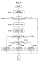
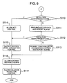
- Figs. 5 and 6 show a processing flow described above.
- step S101 the radar apparatus mounted in a vehicle is used to detect an obstruction existing in front of the vehicle.
- step S102 the radar apparatus mounted in a vehicle is used to detect an obstruction existing in front of the vehicle.
- step S102 the radar apparatus mounted in a vehicle is used to detect an obstruction existing in front of the vehicle.
- step S102 the radar apparatus mounted in a vehicle is used to detect an obstruction existing in front of the vehicle.
- a moving speed of the obstruction is calculated to judge whether the moving speed is larger than or equal to a predetermined value Vc.
- the obstruction is judged to be a vehicle and the processing procedure proceeds to S103. Further, when the moving speed is smaller than or equal to the predetermined value Vc, the processing procedure skips the processing of judging the detection performance level and proceeds to S110.
- step S103 an RCS value ⁇ is calculated from a received power for the vehicle and a headway distance and an average value ⁇ ave of the RCS value is calculated in S104.
- step S105 the RCS average value ⁇ ave is compared with S 1 and when the RCS average value ⁇ ave is larger than S 1 , the detection performance level is judged to be 2. Further, when the RCS average value is smaller than or equal to S 1 , the processing procedure proceeds to S106 and the RCS average value ⁇ ave is compared with S 2 .
- the detection performance level is judged to be 1 and when it is not larger than S 2 , the detection performance level is judged to be 0.
- the detection performance level calculated is used to judge whether the ACC control is stopped or not in S110.
- the processing procedure proceeds to S114 and operation of the ACC control is allowed.
- the processing procedure proceeds to S111 and an alarm for reporting that the detection performance is reduced and the ACC control is stopped is given by means of sound or light (S111).
- S111 sound or light
- the processing procedure proceeds to S115 and operation of the tracking-upon-congestion control is allowed.
- the processing procedure proceeds to S113, in which an alarm for reporting that the detection performance is reduced and the tracking-upon-congestion control is stopped is given by means of sound or light (S113) and the processing procedure proceeds to S116. Operation of the headway distance alarm in S116 and the collision reduction control in S117 is performed regardless of the detection performance level.
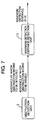
- Fig. 7 shows a next embodiment.
- the obstruction detection unit 1 is used to calculate a distance at which an approaching obstruction begins to be detected or a distance at which an obstruction going away begins to be missed and the maximum detection distance detection unit 11 uses the distance to calculate a maximum detection distance of the obstruction detection unit 1. Its processing flow is shown in Fig. 9.
- an obstruction is detected in step S201 and it is judged whether the obstruction is a newly detected obstruction or not in S202.
- a distance to the obstruction is regarded as a maximum detection distance in S203 while when it is an already detected obstruction, the processing procedure jumps to S204.
- S204 it is judged whether the already detected obstruction is missed or not.
- the processing procedure proceeds to S206, in which the distance at which the obstruction is missed is regarded as the maximum detection distance.
- S207 the maximum detection distance is used to calculate its average value. The calculated average value of the maximum detection distance is used to decide the detection performance level as shown in Fig. 2.
- Fig. 8 shows a next embodiment.
- the obstruction detection unit 1, the detection performance level judgment unit 2 and an external output unit 13 may be included in the radar apparatus 12 to thereby output the detection performance level classified into the plurality of levels outside of the radar apparatus 12.
- the detection performance level is divided into three levels, while it may be divided two or four levels.
- the detection performance level of the radar apparatus is detected and even when the detection performance level is reduced, control of vehicle and operation control of the alarm controller are made individually so that the detection information of the radar apparatus can be utilized at the maximum and accordingly the safety can be improved.
- the operation stopped state of vehicle control or alarm control can be notified to the driver to thereby enhance the safety of the system.
- the RCS value of the moving body detected can be used to detect the detection performance of the radar apparatus, so that the detection performance can be detected automatically.
- the maximum detection distance of the detected moving body or stationary object can be used to detect the detection performance of the radar apparatus, so that the detection performance can be detected automatically.
- the detection performance level of the radar apparatus can be outputted outside, so that the external controller can judge to stop operation individually.
Landscapes
- Engineering & Computer Science (AREA)
- Radar, Positioning & Navigation (AREA)
- Remote Sensing (AREA)
- Physics & Mathematics (AREA)
- Computer Networks & Wireless Communication (AREA)
- General Physics & Mathematics (AREA)
- Electromagnetism (AREA)
- Radar Systems Or Details Thereof (AREA)
- Traffic Control Systems (AREA)
- Control Of Driving Devices And Active Controlling Of Vehicle (AREA)
- Controls For Constant Speed Travelling (AREA)
- Control Of Vehicle Engines Or Engines For Specific Uses (AREA)
Abstract
Description
Claims (19)
- A control apparatus for a vehicle comprising:obstruction detection means (1) for measuring a headway distance until an obstruction existing ahead of said vehicle by means of a radar apparatus;means (5-8) for performing vehicle control or alarm control on the basis of said headway distance;means (2) for detecting detection performance of said obstruction detection means (1) in a vehicle in which said obstruction detection means is used to perform two or more controls containing said vehicle control or alarm control; andmeans (4) for controlling to stop operation of said vehicle control or alarm control in accordance with said detection performance individually.
- A control apparatus for a vehicle according to Claim 1, further comprising means (3) for notifying an operation stopped state of said vehicle control or alarm control to a driver.
- A radar apparatus mounted in a vehicle, comprising:obstruction detection means (1) for detecting an obstruction existing ahead of said vehicle by means of said radar apparatus;means (9) for acquiring a speed of the vehicle;means (10) for identifying a moving body from said obstruction on the basis of said speed;means of calculating an RCS value of said moving body;means for statistically processing said RCS value; andmeans (2) for detecting detection performance of said obstruction detection means on the basis of a result of said statistical processing.
- A radar apparatus mounted in a vehicle, comprising:obstruction detection means (1) for detecting an obstruction existing ahead of said vehicle by means of said radar apparatus;means (1) for acquiring a distance at which an approaching obstruction begins to be detected or a distance at which an obstruction going away begins to be missed, andmeans (2) for detecting detection performance of said obstruction detection means (1) on the basis of said distance at which the approaching obstruction begins to be detected or said distance at which the obstruction going away begins to be missed.
- A radar apparatus mounted in a vehicle, comprising:obstruction detection means (1) for measuring a headway distance until an obstruction existing ahead of said vehicle or a relative speed to the obstruction;means (2) for classifying detection performance of said obstruction detection means into a plurality of levels, andmeans (13) for outputting said level outside.
- A vehicle comprising:wherein traveling control of said vehicle is performed on the basis of said speed of said vehicle and/or said measured headway distance;means (9) for acquiring a speed of said vehicle;obstruction detection means (1) for measuring a headway distance until an obstruction existing ahead of said vehicle; andmeans (3) for notifying information concerning a relation of said vehicle and said obstruction to a driver on the basis of said speed of said vehicle and/or said measured headway distance;
said vehicle further comprising:wherein a method of said notification by said notifying means is changed on the basis of said judged detection performance.means (2) for judging detection performance of said obstruction detection means (1); - A control apparatus of a vehicle, wherein:a vehicle speed is acquired,a headway distance until an obstruction existing ahead of said vehicle is measured by means of obstruction detection means,information concerning a relation of said vehicle and said obstruction is notified to a driver on the basis of said speed of said vehicle and/or said measured headway distance, andtraveling control of said vehicle is performed on the basis of said speed of said vehicle and/or said measured headway distance,detection performance of said obstruction detection means (1) is judged; anda method of said notification of said information to the driver is changed on the basis of said judged detection performance.
- A vehicle according to Claim 6, further comprising
means for canceling said traveling control of said vehicle on the basis of said judged detection performance. - A vehicle according to Claim 8, further comprising
means for notifying the driver that said traveling control of said vehicle has been canceled. - A vehicle according to Claim 6, further comprising
means for notifying the driver that said method of said notification by said notifying means has been changed. - A radar system mounted in a vehicle, comprising:means (1) for detecting an obstruction;means for calculating an RCS value of said detected obstruction on the basis of a speed of said vehicle acquired by means for acquiring said speed of said vehicle; andmeans (2) for judging detection performance of said obstruction detection means (1) on the basis of said RCS value.
- A method of judging detection performance of obstruction detection means (1), comprising the steps of:acquiring a speed of a vehicle;detecting an obstruction by means of obstruction detection means (1);calculating an RCS value of said detected obstruction by means of said speed of said vehicle; andcomparing a value calculated on the basis of said RCS value with a predetermined value set previously to thereby judge detection performance of said obstruction detection means (1).
- A vehicle according to Claim 6, wherein
said means (2) for judging detection performance of said obstruction detection means (1) comprises
means for calculating an RCS value of said detected obstruction on the basis of said speed of said vehicle and comparing a value calculated on the basis of said RCS value with a predetermined value set previously to thereby judge detection performance of said obstruction detection means. - A radar system mounted in a vehicle, comprising:obstruction detection means (1) for measuring a headway distance until an obstruction existing ahead of said vehicle;storage means for storing a distance at which an obstruction approaching to said vehicle begins to be detected or a distance at which an obstruction going away from said vehicle begins to be missed as an initial value when said obstruction detection means is normal;means for calculating a current value of said distance at which the obstruction approaching to said vehicle begins to be detected or said distance at which the obstruction going away from said vehicle begins to be missed; andjudgment means for comparing said initial value with said current value to thereby judging detection performance of said obstruction detection means.
- A method of judging detection performance of obstruction detection means (1), comprising the steps of:setting as an initial value a distance at which an obstruction approaching to a vehicle begins to be detected when said obstruction detection means is normal, said obstruction being detected by said obstruction detection means;calculating a current value of the distance at which said obstruction approaching to said vehicle begins to be detected; andcomparing said initial value with said current value to thereby judge detection performance of said obstruction detection means (1).
- A method of judging detection performance of obstruction detection means (1), comprising the steps of:setting as an initial value a distance at which an obstruction going away from a vehicle begins to be missed when said obstruction detection means is normal, said obstruction being detected by said obstruction detection means;calculating a current value of the distance at which said obstruction going away from said vehicle begins to be missed; andcomparing said initial value with said current value to thereby judge detection performance of said obstruction detection means (1).
- A vehicle according to Claim 6, wherein
said means (2) for judging the detection performance of said obstruction detection means (1), comprising:means for setting as an initial value a distance at which an obstruction approaching to said vehicle begins to be detected and/or a distance at which an obstruction going away from said vehicle begins to be missed when said obstruction detection means is normal, calculating a current value of said distance at which said obstruction approaching to said vehicle begins to be detected and/or a current value of said distance at which said obstruction going away from said vehicle begins to be missed, and comparing said initial value with said current value to thereby judge the detection performance of said obstruction detection means. - A vehicle control apparatus according to Claim 1, further comprising means for classifying said detection performance into a plurality of levels.
- A control apparatus for a vehicle according to Claim 1, wherein said obstruction detection means is a millimeter-wave radar.
Applications Claiming Priority (2)
| Application Number | Priority Date | Filing Date | Title |
|---|---|---|---|
| JP2001217515 | 2001-07-18 | ||
| JP2001217515A JP3893912B2 (en) | 2001-07-18 | 2001-07-18 | Vehicle control device |
Publications (3)
| Publication Number | Publication Date |
|---|---|
| EP1278075A2 true EP1278075A2 (en) | 2003-01-22 |
| EP1278075A3 EP1278075A3 (en) | 2005-03-30 |
| EP1278075B1 EP1278075B1 (en) | 2013-01-23 |
Family
ID=19051816
Family Applications (1)
| Application Number | Title | Priority Date | Filing Date |
|---|---|---|---|
| EP02003282A Expired - Lifetime EP1278075B1 (en) | 2001-07-18 | 2002-02-22 | Vehicle control apparatus with obstruction detection unit |
Country Status (3)
| Country | Link |
|---|---|
| US (2) | US6819283B2 (en) |
| EP (1) | EP1278075B1 (en) |
| JP (1) | JP3893912B2 (en) |
Cited By (4)
| Publication number | Priority date | Publication date | Assignee | Title |
|---|---|---|---|---|
| EP1519203A1 (en) * | 2003-09-25 | 2005-03-30 | Robert Bosch Gmbh | Method for the determination of the measuring characteristics of a radar sensor of a motor vehicle |
| CN105189236A (en) * | 2013-05-29 | 2015-12-23 | 万国卡车知识产权有限公司 | Adaptive automatic transmission control system |
| EP3299839A1 (en) * | 2016-09-26 | 2018-03-28 | Continental Automotive GmbH | Method, monitoring unit, and radar sensor |
| DE102018213169A1 (en) * | 2018-08-07 | 2020-02-13 | Continental Automotive Gmbh | RADAR CROSS-SECTION (RCS) MONITOR FOR DETECTION OF RESTRICTION |
Families Citing this family (31)
| Publication number | Priority date | Publication date | Assignee | Title |
|---|---|---|---|---|
| US6679702B1 (en) * | 2001-12-18 | 2004-01-20 | Paul S. Rau | Vehicle-based headway distance training system |
| WO2004052597A1 (en) * | 2002-12-10 | 2004-06-24 | Honda Motor Co.,Ltd. | Robot control device, robot control method, and robot control program |
| JP2004255928A (en) * | 2003-02-24 | 2004-09-16 | Denso Corp | Vehicle control device |
| JP2004309190A (en) | 2003-04-03 | 2004-11-04 | Hitachi Ltd | Radar equipment |
| JP2004361155A (en) * | 2003-06-03 | 2004-12-24 | Fujitsu Ten Ltd | Target object determination device, target object determination device, and determination auxiliary device |
| JP4033106B2 (en) * | 2003-10-22 | 2008-01-16 | 日産自動車株式会社 | Ranging performance degradation detection device for vehicles |
| JP2005271721A (en) * | 2004-03-24 | 2005-10-06 | Denso Corp | Vehicle control apparatus and program |
| JP4259368B2 (en) * | 2004-03-26 | 2009-04-30 | 三菱自動車工業株式会社 | Nose view monitor device |
| US7492306B2 (en) * | 2006-03-24 | 2009-02-17 | Tdk Corporation | Boundary crossing object detection system |
| JP4254821B2 (en) * | 2006-08-15 | 2009-04-15 | トヨタ自動車株式会社 | Braking control device |
| DE102007053989A1 (en) * | 2007-11-13 | 2009-05-14 | Wabco Gmbh | Method and arrangement for warning against obstacles with insufficient headroom and / or insufficient passage width |
| JP2009187424A (en) * | 2008-02-08 | 2009-08-20 | Alpine Electronics Inc | Perimeter monitoring device and perimeter monitoring method |
| US8755997B2 (en) * | 2008-07-30 | 2014-06-17 | Honeywell International Inc. | Laser ranging process for road and obstacle detection in navigating an autonomous vehicle |
| US8364334B2 (en) * | 2008-10-30 | 2013-01-29 | Honeywell International Inc. | System and method for navigating an autonomous vehicle using laser detection and ranging |
| JP5078944B2 (en) * | 2009-04-27 | 2012-11-21 | 本田技研工業株式会社 | Vehicle travel control device |
| US7982637B2 (en) * | 2009-08-14 | 2011-07-19 | Stephen Allyn Joyce | Data encoding method |
| JP2011122876A (en) * | 2009-12-09 | 2011-06-23 | Toyota Central R&D Labs Inc | Obstacle detector |
| JP5601930B2 (en) * | 2010-08-09 | 2014-10-08 | 本田技研工業株式会社 | Vehicle display device |
| US9511751B2 (en) * | 2011-07-22 | 2016-12-06 | GM Global Technology Operations LLC | Object identification and active safety control for vehicles |
| JP5953716B2 (en) * | 2011-11-28 | 2016-07-20 | トヨタ自動車株式会社 | Vehicle control apparatus, specific object determination apparatus, specific object determination method, specific object determination program |
| US9810783B2 (en) * | 2014-05-15 | 2017-11-07 | Empire Technology Development Llc | Vehicle detection |
| JP6470039B2 (en) * | 2014-12-26 | 2019-02-13 | 日立オートモティブシステムズ株式会社 | Vehicle control system |
| US9725091B2 (en) * | 2015-07-02 | 2017-08-08 | Cummins, Inc. | Vehicle speed management integrated with vehicle monitoring system |
| DE102016223068A1 (en) * | 2016-11-23 | 2018-05-24 | Robert Bosch Gmbh | Method for detecting blindness in radar sensors for motor vehicles |
| JP6809331B2 (en) * | 2017-03-28 | 2021-01-06 | トヨタ自動車株式会社 | Vehicle control device |
| DE102017106851A1 (en) * | 2017-03-30 | 2018-10-04 | Geopraevent Ag | Radar system with clearing device |
| DE102018205322A1 (en) * | 2018-04-10 | 2019-10-10 | Audi Ag | Method and control device for detecting a malfunction of at least one environmental sensor of a motor vehicle |
| CN108535714B (en) * | 2018-05-25 | 2021-10-22 | 厦门精益远达智能科技有限公司 | Method and device for detecting object sheltered in open space by millimeter wave radar |
| DE102019111679A1 (en) | 2019-05-06 | 2020-11-12 | S.M.S Smart Microwave Sensors Gmbh | Procedure for recording road users |
| WO2020240813A1 (en) | 2019-05-31 | 2020-12-03 | 三菱電機株式会社 | Object detection system and object detection method |
| JP7424237B2 (en) * | 2020-07-20 | 2024-01-30 | 株式会社デンソー | distance detection device |
Family Cites Families (27)
| Publication number | Priority date | Publication date | Assignee | Title |
|---|---|---|---|---|
| US3703702A (en) * | 1970-11-16 | 1972-11-21 | Toyota Motor Co Ltd | Air bag safety device for vehicle passengers |
| JPS5437495A (en) * | 1977-08-29 | 1979-03-19 | Nissan Motor | Radar diagnosing device |
| JPH0652500A (en) * | 1992-08-03 | 1994-02-25 | Mazda Motor Corp | Travelling safety device for vehicle |
| US5530651A (en) | 1992-08-03 | 1996-06-25 | Mazda Motor Corporation | Running-safety system for an automotive vehicle |
| US5432516A (en) * | 1994-01-13 | 1995-07-11 | Armatron International, Inc. | Radar obstacle detection system with self test |
| JP3470453B2 (en) * | 1995-04-06 | 2003-11-25 | 株式会社デンソー | Inter-vehicle distance control device |
| JP3644149B2 (en) * | 1996-09-10 | 2005-04-27 | 日産自動車株式会社 | Inter-vehicle distance control type constant speed travel device |
| JPH1194946A (en) * | 1997-07-23 | 1999-04-09 | Denso Corp | Obstacle recognition device for vehicles |
| JP2000113397A (en) * | 1998-10-08 | 2000-04-21 | Mitsubishi Motors Corp | Vehicle travel control device |
| JP3853991B2 (en) * | 1998-11-04 | 2006-12-06 | 本田技研工業株式会社 | Vehicle travel safety device |
| JP4045041B2 (en) * | 1999-02-05 | 2008-02-13 | 本田技研工業株式会社 | Radar apparatus and radar apparatus abnormality detection method |
| JP2000241529A (en) * | 1999-02-22 | 2000-09-08 | Honda Motor Co Ltd | Radar apparatus and radar apparatus abnormality detection method |
| JP4045043B2 (en) * | 1999-02-24 | 2008-02-13 | 本田技研工業株式会社 | Radar equipment |
| JP3308231B2 (en) * | 1999-05-17 | 2002-07-29 | 本田技研工業株式会社 | Radar equipment |
| JP4564611B2 (en) * | 1999-08-04 | 2010-10-20 | 本田技研工業株式会社 | Radar equipment |
| DE19937723C2 (en) * | 1999-08-10 | 2001-10-04 | Bosch Gmbh Robert | Method and device for determining a height angle error of a multi-beam radar sensor |
| DE19945250B4 (en) * | 1999-09-21 | 2011-06-09 | Bayerische Motoren Werke Aktiengesellschaft | Method and device for state detection in a system for automatic longitudinal and / or transverse control in a motor vehicle |
| JP3411866B2 (en) * | 1999-10-25 | 2003-06-03 | 株式会社日立製作所 | Millimeter wave radar device |
| JP3562408B2 (en) * | 1999-11-10 | 2004-09-08 | 株式会社デンソー | Radar device characteristic detecting device and recording medium |
| JP3600499B2 (en) * | 2000-03-17 | 2004-12-15 | 三菱電機株式会社 | FM pulse Doppler radar device |
| JP4390359B2 (en) * | 2000-04-28 | 2009-12-24 | 富士通株式会社 | FM-CW radar equipment |
| GB2363016A (en) * | 2000-05-31 | 2001-12-05 | Roke Manor Research | Automotive radar |
| US6469659B1 (en) * | 2001-05-03 | 2002-10-22 | Delphi Technologies, Inc. | Apparatus and method for detecting radar obstruction |
| JP4698087B2 (en) * | 2001-08-15 | 2011-06-08 | 富士通テン株式会社 | Radar horizontal axis deviation occurrence detection apparatus, axis deviation determination apparatus, and axis deviation correction apparatus |
| US6611227B1 (en) * | 2002-08-08 | 2003-08-26 | Raytheon Company | Automotive side object detection sensor blockage detection system and related techniques |
| JP3757936B2 (en) * | 2002-11-29 | 2006-03-22 | 株式会社デンソー | Obstacle recognition device for vehicles |
| JP4313089B2 (en) * | 2003-05-23 | 2009-08-12 | 富士通テン株式会社 | Radar apparatus for automobile and its mounting direction adjusting method |
-
2001
- 2001-07-18 JP JP2001217515A patent/JP3893912B2/en not_active Expired - Fee Related
-
2002
- 2002-02-22 EP EP02003282A patent/EP1278075B1/en not_active Expired - Lifetime
- 2002-02-27 US US10/083,473 patent/US6819283B2/en not_active Expired - Lifetime
-
2003
- 2003-12-19 US US10/739,223 patent/US7259711B2/en not_active Expired - Lifetime
Cited By (5)
| Publication number | Priority date | Publication date | Assignee | Title |
|---|---|---|---|---|
| EP1519203A1 (en) * | 2003-09-25 | 2005-03-30 | Robert Bosch Gmbh | Method for the determination of the measuring characteristics of a radar sensor of a motor vehicle |
| CN105189236A (en) * | 2013-05-29 | 2015-12-23 | 万国卡车知识产权有限公司 | Adaptive automatic transmission control system |
| CN105189236B (en) * | 2013-05-29 | 2018-01-02 | 万国卡车知识产权有限公司 | Self-adapting automatic gear shift case control system |
| EP3299839A1 (en) * | 2016-09-26 | 2018-03-28 | Continental Automotive GmbH | Method, monitoring unit, and radar sensor |
| DE102018213169A1 (en) * | 2018-08-07 | 2020-02-13 | Continental Automotive Gmbh | RADAR CROSS-SECTION (RCS) MONITOR FOR DETECTION OF RESTRICTION |
Also Published As
| Publication number | Publication date |
|---|---|
| EP1278075A3 (en) | 2005-03-30 |
| US7259711B2 (en) | 2007-08-21 |
| JP3893912B2 (en) | 2007-03-14 |
| US20040130481A1 (en) | 2004-07-08 |
| US6819283B2 (en) | 2004-11-16 |
| JP2003030798A (en) | 2003-01-31 |
| US20030016161A1 (en) | 2003-01-23 |
| EP1278075B1 (en) | 2013-01-23 |
Similar Documents
| Publication | Publication Date | Title |
|---|---|---|
| EP1278075B1 (en) | Vehicle control apparatus with obstruction detection unit | |
| EP3208165B1 (en) | Vehicle safety assist system | |
| JP3232724B2 (en) | Inter-vehicle distance control device | |
| US6567039B2 (en) | Road-shape recognition system | |
| EP2302412B1 (en) | System and method for evaluation of an automotive vehicle forward collision threat | |
| US20190219681A1 (en) | Mining work machine and obstacle discrimination device | |
| US20150239472A1 (en) | Vehicle-installed obstacle detection apparatus having function for judging motion condition of detected object | |
| US20080042894A1 (en) | Vehicle control system | |
| US7457699B2 (en) | Technique for detecting truck trailer for stop and go adaptive cruise control | |
| JP5938518B2 (en) | Collision safety control device | |
| EP1065087A2 (en) | Automobile running control system for optimum inter-vehicle spacing | |
| US7103478B2 (en) | Vehicular control object determination system | |
| JP2004239792A (en) | Automotive radar equipment | |
| JP2000132799A (en) | Control target sorting device | |
| JP4928896B2 (en) | Vehicle control device | |
| JP2019021027A (en) | Speed bump detection device | |
| JP4944535B2 (en) | Vehicle control device | |
| JP3873967B2 (en) | Weather determination device and weather determination method | |
| KR20190011630A (en) | Smart cruise control apparatus and method with rear impact mitigation function | |
| JP2019021028A (en) | Speed bump position evaluation device and driving support device | |
| JP4757147B2 (en) | Object detection device | |
| JPH0880840A (en) | Brake deterioration detecting system and method | |
| JP5050002B2 (en) | Vehicle object detection device | |
| JP3233123B2 (en) | Inter-vehicle distance control device | |
| KR20100133042A (en) | Driver comfort system and driving control method |
Legal Events
| Date | Code | Title | Description |
|---|---|---|---|
| PUAI | Public reference made under article 153(3) epc to a published international application that has entered the european phase |
Free format text: ORIGINAL CODE: 0009012 |
|
| AK | Designated contracting states |
Kind code of ref document: A2 Designated state(s): AT BE CH CY DE DK ES FI FR GB GR IE IT LI LU MC NL PT SE TR |
|
| AX | Request for extension of the european patent |
Free format text: AL;LT;LV;MK;RO;SI |
|
| RIC1 | Information provided on ipc code assigned before grant |
Ipc: 7G 01S 13/93 B Ipc: 7G 01S 7/40 A |
|
| PUAL | Search report despatched |
Free format text: ORIGINAL CODE: 0009013 |
|
| AK | Designated contracting states |
Kind code of ref document: A3 Designated state(s): AT BE CH CY DE DK ES FI FR GB GR IE IT LI LU MC NL PT SE TR |
|
| AX | Request for extension of the european patent |
Extension state: AL LT LV MK RO SI |
|
| 17P | Request for examination filed |
Effective date: 20050721 |
|
| AKX | Designation fees paid |
Designated state(s): DE FR GB IT |
|
| GRAP | Despatch of communication of intention to grant a patent |
Free format text: ORIGINAL CODE: EPIDOSNIGR1 |
|
| GRAS | Grant fee paid |
Free format text: ORIGINAL CODE: EPIDOSNIGR3 |
|
| GRAA | (expected) grant |
Free format text: ORIGINAL CODE: 0009210 |
|
| RIN1 | Information on inventor provided before grant (corrected) |
Inventor name: KURODA, HIROSHI, HITACHI,LTD. INTELL.PROP.GROUP Inventor name: OKAI, FUMIHIKO, HITACHI,LTD. INTELL.PROP.GROUP |
|
| RAP1 | Party data changed (applicant data changed or rights of an application transferred) |
Owner name: HITACHI, LTD. |
|
| AK | Designated contracting states |
Kind code of ref document: B1 Designated state(s): DE FR GB IT |
|
| REG | Reference to a national code |
Ref country code: GB Ref legal event code: FG4D |
|
| REG | Reference to a national code |
Ref country code: DE Ref legal event code: R096 Ref document number: 60244441 Country of ref document: DE Effective date: 20130321 |
|
| PLBE | No opposition filed within time limit |
Free format text: ORIGINAL CODE: 0009261 |
|
| STAA | Information on the status of an ep patent application or granted ep patent |
Free format text: STATUS: NO OPPOSITION FILED WITHIN TIME LIMIT |
|
| GBPC | Gb: european patent ceased through non-payment of renewal fee |
Effective date: 20130423 |
|
| PG25 | Lapsed in a contracting state [announced via postgrant information from national office to epo] |
Ref country code: IT Free format text: LAPSE BECAUSE OF FAILURE TO SUBMIT A TRANSLATION OF THE DESCRIPTION OR TO PAY THE FEE WITHIN THE PRESCRIBED TIME-LIMIT Effective date: 20130123 |
|
| 26N | No opposition filed |
Effective date: 20131024 |
|
| PG25 | Lapsed in a contracting state [announced via postgrant information from national office to epo] |
Ref country code: GB Free format text: LAPSE BECAUSE OF NON-PAYMENT OF DUE FEES Effective date: 20130423 |
|
| REG | Reference to a national code |
Ref country code: DE Ref legal event code: R097 Ref document number: 60244441 Country of ref document: DE Effective date: 20131024 |
|
| REG | Reference to a national code |
Ref country code: FR Ref legal event code: PLFP Year of fee payment: 15 |
|
| REG | Reference to a national code |
Ref country code: FR Ref legal event code: PLFP Year of fee payment: 16 |
|
| REG | Reference to a national code |
Ref country code: FR Ref legal event code: PLFP Year of fee payment: 17 |
|
| PGFP | Annual fee paid to national office [announced via postgrant information from national office to epo] |
Ref country code: DE Payment date: 20200211 Year of fee payment: 19 |
|
| PGFP | Annual fee paid to national office [announced via postgrant information from national office to epo] |
Ref country code: FR Payment date: 20200113 Year of fee payment: 19 |
|
| REG | Reference to a national code |
Ref country code: DE Ref legal event code: R119 Ref document number: 60244441 Country of ref document: DE |
|
| PG25 | Lapsed in a contracting state [announced via postgrant information from national office to epo] |
Ref country code: FR Free format text: LAPSE BECAUSE OF NON-PAYMENT OF DUE FEES Effective date: 20210228 Ref country code: DE Free format text: LAPSE BECAUSE OF NON-PAYMENT OF DUE FEES Effective date: 20210901 |