EP1277972A1 - Spreizdübel - Google Patents
Spreizdübel Download PDFInfo
- Publication number
- EP1277972A1 EP1277972A1 EP02405571A EP02405571A EP1277972A1 EP 1277972 A1 EP1277972 A1 EP 1277972A1 EP 02405571 A EP02405571 A EP 02405571A EP 02405571 A EP02405571 A EP 02405571A EP 1277972 A1 EP1277972 A1 EP 1277972A1
- Authority
- EP
- European Patent Office
- Prior art keywords
- expansion
- fastening element
- segments
- element according
- setting direction
- Prior art date
- Legal status (The legal status is an assumption and is not a legal conclusion. Google has not performed a legal analysis and makes no representation as to the accuracy of the status listed.)
- Granted
Links
- 239000004033 plastic Substances 0.000 claims description 8
- 239000002184 metal Substances 0.000 claims description 7
- 238000001125 extrusion Methods 0.000 claims description 3
- 230000000295 complement effect Effects 0.000 description 1
- 238000004519 manufacturing process Methods 0.000 description 1
- 238000000465 moulding Methods 0.000 description 1
Images
Classifications
-
- F—MECHANICAL ENGINEERING; LIGHTING; HEATING; WEAPONS; BLASTING
- F16—ENGINEERING ELEMENTS AND UNITS; GENERAL MEASURES FOR PRODUCING AND MAINTAINING EFFECTIVE FUNCTIONING OF MACHINES OR INSTALLATIONS; THERMAL INSULATION IN GENERAL
- F16B—DEVICES FOR FASTENING OR SECURING CONSTRUCTIONAL ELEMENTS OR MACHINE PARTS TOGETHER, e.g. NAILS, BOLTS, CIRCLIPS, CLAMPS, CLIPS OR WEDGES; JOINTS OR JOINTING
- F16B13/00—Dowels or other devices fastened in walls or the like by inserting them in holes made therein for that purpose
- F16B13/04—Dowels or other devices fastened in walls or the like by inserting them in holes made therein for that purpose with parts gripping in the hole or behind the reverse side of the wall after inserting from the front
- F16B13/06—Dowels or other devices fastened in walls or the like by inserting them in holes made therein for that purpose with parts gripping in the hole or behind the reverse side of the wall after inserting from the front combined with expanding sleeve
- F16B13/063—Dowels or other devices fastened in walls or the like by inserting them in holes made therein for that purpose with parts gripping in the hole or behind the reverse side of the wall after inserting from the front combined with expanding sleeve by the use of an expander
- F16B13/066—Dowels or other devices fastened in walls or the like by inserting them in holes made therein for that purpose with parts gripping in the hole or behind the reverse side of the wall after inserting from the front combined with expanding sleeve by the use of an expander fastened by extracting a separate expander-part, actuated by the screw, nail or the like
-
- F—MECHANICAL ENGINEERING; LIGHTING; HEATING; WEAPONS; BLASTING
- F16—ENGINEERING ELEMENTS AND UNITS; GENERAL MEASURES FOR PRODUCING AND MAINTAINING EFFECTIVE FUNCTIONING OF MACHINES OR INSTALLATIONS; THERMAL INSULATION IN GENERAL
- F16B—DEVICES FOR FASTENING OR SECURING CONSTRUCTIONAL ELEMENTS OR MACHINE PARTS TOGETHER, e.g. NAILS, BOLTS, CIRCLIPS, CLAMPS, CLIPS OR WEDGES; JOINTS OR JOINTING
- F16B37/00—Nuts or like thread-engaging members
- F16B37/08—Quickly-detachable or mountable nuts, e.g. consisting of two or more parts; Nuts movable along the bolt after tilting the nut
- F16B37/0871—Quickly-detachable or mountable nuts, e.g. consisting of two or more parts; Nuts movable along the bolt after tilting the nut engaging the bolt laterally, i.e. without the need to engage the end of the bolt
- F16B37/0885—Quickly-detachable or mountable nuts, e.g. consisting of two or more parts; Nuts movable along the bolt after tilting the nut engaging the bolt laterally, i.e. without the need to engage the end of the bolt in two halves hingedly connected
Definitions
- the invention relates to a fastening element with a cylindrical, from the setting direction side End at least partially longitudinally slotted, expansion sleeve, which has a through hole has, and with a retractable into the through hole, one in the setting direction widening outer contour, expanding body, which has a bore with a Has internal thread.
- Fasteners of the type mentioned are used in a wide variety of applications, for example as a segment anchor in a concrete component.
- the fastener is inserted into a borehole created in the component.
- a load acting against the setting direction causes the expansion body to move into the Expansion sleeve is pulled and this expands radially. This causes a spread the expansion sleeve in the borehole.
- An advantage of the known fastening element is that the design of the load application means and the fastener pre-assembly in a simple manner ensure that the load engaging means designed as a screw in the setting direction by the Expansion sleeve is guided and the expansion body at the end of the screw on the setting direction is screwed on.
- a disadvantage of the known fastening means is that the load application means during the pre-assembly must be screwed into the internal thread of the expansion body. This requires on the one hand, a lot of time and on the other hand requires a perfectly cut Load application means, otherwise screwing the load application means into the Internal thread designed very difficult or even impossible.
- the present invention has for its object a fastener with a create an expandable expanding sleeve that is both a handy Pre-assembly ensures and is also economical to manufacture.
- the object is achieved in that the expansion body at least consists of two body segments.
- the expansion body consists of several body segments, one is extremely easy pre-assembly of the fastener ensured, as this by simple Assembling the body segments pre-assembled at the desired point on the load application means becomes.
- the pre-assembly is essentially independent of the state of the Outside contour of the load application means, and thus, for example, a time-consuming is eliminated Screwing the expansion body onto the load application means.
- Adjacent body segments are advantageously connected to one another by joints, to prevent loss of one or more body segments of the expansion body. Furthermore, the handiness of the fastening element is increased by the use of joints during pre-assembly on the load attachment device. Especially if, for example, all of them adjacent body segments are connected to each other by joints a behavior that is equivalent to a one-piece design of the expansion body.
- At least one body segment is adjacent to one Body segment connectable by a connecting device so that by the individual body segments formed spreading body on the load application means, advantageously is detachable, fixable.
- the expansion sleeve is preferably divided into at least two expansion segments to make it simple and thus to ensure easy pre-assembly.
- Adjacent spreading segments are advantageously connected to one another by joints, to ensure simple pre-assembly of the expansion sleeve on the load application means.
- At least one spreading segment with an adjacent spreading segment connectable by a connecting device, so that through the individual spreading segments formed expansion sleeve can be fixed on the load application means.
- the expansion sleeve is made of metal, at least partially with a Plastic is overmolded.
- the expansion body is advantageously made of metal, at least partially with a Plastic is overmolded for easy molding of additional elements, such as to ensure the connecting device.
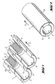
- 1 to 3 is a fastener according to the invention with a cylindrical, from the setting direction end, at least partially longitudinally slotted expansion sleeve 1, which has a through hole 3, shown.
- the expansion sleeve 1 is opposed by one the setting direction S retractable into the through hole 3, radial expansion body 2 expandable.
- the expansion body 2, formed from two body segments 7, 8, has one approximately in the center in the setting direction S extending bore 4, which with an inner profile, in particular one Internal thread 5 is provided. Furthermore, the conically shaped outer contour 6 widens of the expansion body 2 in the setting direction S.
- the expansion sleeve 1 formed from two expansion segments 9, 11 points in the setting direction End region of the through hole 3 has a receiving region 12 with a conical, complementary trained for the outer contour of the expansion body 2, the inner contour, which in Setting direction S expanded.
- the expansion body 2 is in the receiving area 12 of the expansion sleeve 1 axially displaceable.
- the expansion body 2 is, for example, by a, not shown,
- the predetermined breaking point is releasably connected to the expansion sleeve 1.
- the two spreading segments 9, 11 are connected to one another by a joint (13) which is, for example, plastic connected.
- the two expansion segments 9, 11 by one, for reasons of clarity not shown, connecting device connectable to each other.
- the connecting device is designed, for example, as a snap lock.
- the expansion sleeve 1 is made of metal, which at least partially extrusion-coated with a plastic is.
- the expansion body 2 is for example made of metal, plastic or metal, at least is partially overmolded with a plastic.
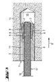
- the fastening element according to the invention is in one, in a base 14 created, hole 15 shown in the set state.
- bolt 17 serves as a load application means.
- the bolt 17 engages with its outer profile 16 positively into the internal thread 5 of the expansion body 2.
- One against the Setting direction S acting and acting on the bolt 17 leads to a shift of the expansion body 2 mounted in the receiving area 12 of the through bore 3 the setting direction S and thus to a radial expansion of the expansion sleeve 1.
Landscapes
- Engineering & Computer Science (AREA)
- General Engineering & Computer Science (AREA)
- Mechanical Engineering (AREA)
- Dowels (AREA)
- Piles And Underground Anchors (AREA)
- Tents Or Canopies (AREA)
- Joining Of Building Structures In Genera (AREA)
Abstract
Description
- Fig. 1
- eine perspektivische Ansicht des erfindungsgemässen Befestigungselementes im auseinandergeklappten Zustand,
- Fig. 2
- eine perspektivische Ansicht des in Fig. 1 dargestellten Befestigungselementes, im zusammengeklappten Zustand,
- Fig. 3
- einen Längsschnitt des in Fig. 1 dargestellten Befestigungselementes, im gesetzten Zustand, mit einem eingeführten Lastangriffsmittel.
Claims (8)
- Befestigungselement mit einer zylindrischen, vom setzrichtungsseitigen Ende her wenigstens teilweise längsgeschlitzten, Spreizhülse (1), die eine Durchgangsbohrung (3) aufweist, und mit einem in die Durchgangsbohrung (3) einziehbaren, eine sich in Setzrichtung (S) erweiternden Aussenkontur aufweisenden, Spreizkörper (2), der eine Bohrung (4) mit einem Innengewinde (5) aufweist, dadurch gekennzeichnet, dass der Spreizkörper (2) aus zumindest zwei Körpersegmenten (7, 8) besteht.
- Befestigungselement nach Anspruch 1, dadurch gekennzeichnet, dass benachbarte Körpersegmente (7, 8) durch Gelenke miteinander verbunden sind.
- Befestigungselement nach Anspruch 1, dadurch gekennzeichnet, dass zumindest ein Körpersegment (7) mit einem benachbarten Körpersegment (8) durch eine Verbindungsvorrichtung verbindbar ist.
- Befestigungselement nach einem der Ansprüche 1 bis 3, dadurch gekennzeichnet, dass die Spreizhülse (1) in zumindest zwei Spreizsegmente (9,11) geteilt ist.
- Befestigungselemente nach Anspruch 4, dadurch gekennzeichnet, dass benachbarte Spreizsegmente (9,11) durch Gelenke (12) miteinander verbunden sind.
- Befestigungselement nach Anspruch 4 oder 5, dadurch gekennzeichnet, dass zumindest ein Spreizsegment (9) mit einem benachbarten Spreizsegment (11) durch eine Verbindungsvorrichtung verbindbar ist.
- Befestigungselement nach einem der Ansprüche 1 bis 6, dadurch gekennzeichnet, dass die Spreizhülse (1) aus Metall, das zumindest teilweise mit einem Kunststoff umspritzt ist, besteht.
- Befestigungselement nach einem der Ansprüche 1 bis 7, dadurch gekennzeichnet, dass die Spreizkörper (2) aus Metall, das zumindest teilweise mit einem Kunststoff umspritzt ist, besteht.
Applications Claiming Priority (2)
| Application Number | Priority Date | Filing Date | Title |
|---|---|---|---|
| DE10134604 | 2001-07-17 | ||
| DE10134604A DE10134604A1 (de) | 2001-07-17 | 2001-07-17 | Spreizdübel |
Publications (2)
| Publication Number | Publication Date |
|---|---|
| EP1277972A1 true EP1277972A1 (de) | 2003-01-22 |
| EP1277972B1 EP1277972B1 (de) | 2004-11-10 |
Family
ID=7691999
Family Applications (1)
| Application Number | Title | Priority Date | Filing Date |
|---|---|---|---|
| EP02405571A Expired - Lifetime EP1277972B1 (de) | 2001-07-17 | 2002-07-08 | Spreizdübel |
Country Status (4)
| Country | Link |
|---|---|
| US (1) | US20030017023A1 (de) |
| EP (1) | EP1277972B1 (de) |
| AT (1) | ATE282149T1 (de) |
| DE (2) | DE10134604A1 (de) |
Families Citing this family (11)
| Publication number | Priority date | Publication date | Assignee | Title |
|---|---|---|---|---|
| US7011281B2 (en) * | 2002-02-28 | 2006-03-14 | Karl Guthrie | Expansion bolt |
| US7357363B2 (en) * | 2003-12-30 | 2008-04-15 | Karl Guthrie | Expansion bolt |
| GB2419168B (en) * | 2004-10-18 | 2008-08-20 | Airbus Uk Ltd | A Fastener assembly |
| US20090056267A1 (en) * | 2007-07-12 | 2009-03-05 | Reeves Eric William | Expansible hole anchor |
| US8678730B2 (en) * | 2011-04-19 | 2014-03-25 | Black & Decker Inc. | Anchor stud and method of forming an anchor stud |
| EP3027914A1 (de) * | 2013-07-30 | 2016-06-08 | Gualco, Mario | Verfahren zur installation von verankerungseinheiten und vorrichtung zur durchführung des verfahrens |
| JP6374235B2 (ja) * | 2014-06-27 | 2018-08-15 | 株式会社豊和 | アンカーボルト |
| EP3199823A1 (de) | 2016-01-26 | 2017-08-02 | HILTI Aktiengesellschaft | Spreizanker mit aufgeklipstem spreizteil |
| CN107448443A (zh) * | 2017-08-22 | 2017-12-08 | 苏州威富达精密机械制造有限公司 | 一种可连接套筒 |
| JP7470640B2 (ja) | 2018-02-09 | 2024-04-18 | イマティクス ユーエス,アイエヌシー. | T細胞を製造する方法 |
| CN110307232B (zh) * | 2019-07-03 | 2023-06-16 | 浙江启冠精工机械股份有限公司 | 一种防止松动的螺丝 |
Citations (4)
| Publication number | Priority date | Publication date | Assignee | Title |
|---|---|---|---|---|
| US2955504A (en) * | 1958-06-06 | 1960-10-11 | Louis B Lovrinch | Plastic bolt anchor having means to permit expansion prior to application of bolt and serrations to prevent relative rotation between the body and the sleeve |
| US3172603A (en) * | 1960-11-16 | 1965-03-09 | Star Expansion Ind Corp | Anchoring device |
| DE7538457U (de) * | 1976-04-29 | Fa. Richard Heinze, 4900 Herford | Einschlag- und Spreizdübel für Verbindungs- und Befestigungselemente | |
| US4930961A (en) * | 1988-12-23 | 1990-06-05 | Weis Charles W | Quick lock and release fastener |
Family Cites Families (4)
| Publication number | Priority date | Publication date | Assignee | Title |
|---|---|---|---|---|
| US3546998A (en) * | 1968-09-03 | 1970-12-15 | Wej It Expansion Products Inc | Hinge-type anchor bolt |
| US4702349A (en) * | 1985-09-20 | 1987-10-27 | Zenhaeusern Heinrich | Anchor step |
| DE3719164A1 (de) * | 1987-06-09 | 1988-12-29 | Hilti Ag | Spreizduebel mit begrenzter spreizung |
| US5846041A (en) * | 1997-07-10 | 1998-12-08 | The United States Of America As Represented By The United States Department Of Energy | Nonrotating, self-centering anchor assembly for anchoring a bolt in a borehole |
-
2001
- 2001-07-17 DE DE10134604A patent/DE10134604A1/de not_active Withdrawn
-
2002
- 2002-07-08 EP EP02405571A patent/EP1277972B1/de not_active Expired - Lifetime
- 2002-07-08 DE DE50201499T patent/DE50201499D1/de not_active Expired - Lifetime
- 2002-07-08 AT AT02405571T patent/ATE282149T1/de active
- 2002-07-12 US US10/194,532 patent/US20030017023A1/en not_active Abandoned
Patent Citations (4)
| Publication number | Priority date | Publication date | Assignee | Title |
|---|---|---|---|---|
| DE7538457U (de) * | 1976-04-29 | Fa. Richard Heinze, 4900 Herford | Einschlag- und Spreizdübel für Verbindungs- und Befestigungselemente | |
| US2955504A (en) * | 1958-06-06 | 1960-10-11 | Louis B Lovrinch | Plastic bolt anchor having means to permit expansion prior to application of bolt and serrations to prevent relative rotation between the body and the sleeve |
| US3172603A (en) * | 1960-11-16 | 1965-03-09 | Star Expansion Ind Corp | Anchoring device |
| US4930961A (en) * | 1988-12-23 | 1990-06-05 | Weis Charles W | Quick lock and release fastener |
Also Published As
| Publication number | Publication date |
|---|---|
| ATE282149T1 (de) | 2004-11-15 |
| US20030017023A1 (en) | 2003-01-23 |
| DE10134604A1 (de) | 2003-02-06 |
| DE50201499D1 (de) | 2004-12-16 |
| EP1277972B1 (de) | 2004-11-10 |
Similar Documents
| Publication | Publication Date | Title |
|---|---|---|
| DE3335628C2 (de) | ||
| EP0189000B1 (de) | Spreizdübel für dünnwandige Bauteile | |
| EP1277973B1 (de) | Spreizdübel | |
| EP1277972B1 (de) | Spreizdübel | |
| EP0964168B1 (de) | Hinterschnittdübel | |
| EP0145886B1 (de) | Spreiznagel | |
| EP0908634B1 (de) | Einschlagdübel | |
| EP0874167B1 (de) | Spreizdübel | |
| EP1150024B1 (de) | Befestigungselement | |
| EP2185777A2 (de) | Dämmstoffdübel | |
| EP0171354B1 (de) | Spreizdübel | |
| DE19538898C2 (de) | Schlaganker | |
| EP0995914B1 (de) | Befestigungselement aus Metall mit Innengewinde für die Durchsteckmontage | |
| EP1205674B1 (de) | Spreizdübel | |
| EP1970575A2 (de) | Spreizdübel für zweischaliges Mauerwerk | |
| EP2065535A1 (de) | Dämmstoffhalter | |
| EP0558890B1 (de) | Spreizdübel | |
| EP1159537B1 (de) | Spreizdübel | |
| DE4010999A1 (de) | Befestigungselement | |
| EP0825352B1 (de) | Spreizdübel | |
| DE29810927U1 (de) | Spreizdübel | |
| DE10015202A1 (de) | Spreizdübel | |
| EP0893610B1 (de) | Spreizdübel | |
| EP2314888A2 (de) | Spreizdübel | |
| EP1165970A1 (de) | Spreizdübel |
Legal Events
| Date | Code | Title | Description |
|---|---|---|---|
| PUAI | Public reference made under article 153(3) epc to a published international application that has entered the european phase |
Free format text: ORIGINAL CODE: 0009012 |
|
| AK | Designated contracting states |
Kind code of ref document: A1 Designated state(s): AT BE BG CH CY CZ DE DK EE ES FI FR GB GR IE IT LI LU MC NL PT SE SK TR |
|
| AX | Request for extension of the european patent |
Free format text: AL;LT;LV;MK;RO;SI |
|
| 17P | Request for examination filed |
Effective date: 20030722 |
|
| AKX | Designation fees paid |
Designated state(s): AT BE BG CH CY CZ DE DK EE ES FI FR GB GR IE IT LI LU MC NL PT SE SK TR |
|
| GRAP | Despatch of communication of intention to grant a patent |
Free format text: ORIGINAL CODE: EPIDOSNIGR1 |
|
| GRAS | Grant fee paid |
Free format text: ORIGINAL CODE: EPIDOSNIGR3 |
|
| GRAA | (expected) grant |
Free format text: ORIGINAL CODE: 0009210 |
|
| AK | Designated contracting states |
Kind code of ref document: B1 Designated state(s): AT BE BG CH CY CZ DE DK EE ES FI FR GB GR IE IT LI LU MC NL PT SE SK TR |
|
| PG25 | Lapsed in a contracting state [announced via postgrant information from national office to epo] |
Ref country code: IE Free format text: LAPSE BECAUSE OF FAILURE TO SUBMIT A TRANSLATION OF THE DESCRIPTION OR TO PAY THE FEE WITHIN THE PRESCRIBED TIME-LIMIT Effective date: 20041110 Ref country code: EE Free format text: LAPSE BECAUSE OF FAILURE TO SUBMIT A TRANSLATION OF THE DESCRIPTION OR TO PAY THE FEE WITHIN THE PRESCRIBED TIME-LIMIT Effective date: 20041110 Ref country code: TR Free format text: LAPSE BECAUSE OF FAILURE TO SUBMIT A TRANSLATION OF THE DESCRIPTION OR TO PAY THE FEE WITHIN THE PRESCRIBED TIME-LIMIT Effective date: 20041110 Ref country code: SK Free format text: LAPSE BECAUSE OF FAILURE TO SUBMIT A TRANSLATION OF THE DESCRIPTION OR TO PAY THE FEE WITHIN THE PRESCRIBED TIME-LIMIT Effective date: 20041110 Ref country code: CZ Free format text: LAPSE BECAUSE OF FAILURE TO SUBMIT A TRANSLATION OF THE DESCRIPTION OR TO PAY THE FEE WITHIN THE PRESCRIBED TIME-LIMIT Effective date: 20041110 Ref country code: FI Free format text: LAPSE BECAUSE OF FAILURE TO SUBMIT A TRANSLATION OF THE DESCRIPTION OR TO PAY THE FEE WITHIN THE PRESCRIBED TIME-LIMIT Effective date: 20041110 Ref country code: BG Free format text: LAPSE BECAUSE OF FAILURE TO SUBMIT A TRANSLATION OF THE DESCRIPTION OR TO PAY THE FEE WITHIN THE PRESCRIBED TIME-LIMIT Effective date: 20041110 |
|
| REG | Reference to a national code |
Ref country code: GB Ref legal event code: FG4D Free format text: NOT ENGLISH |
|
| REG | Reference to a national code |
Ref country code: CH Ref legal event code: EP |
|
| REG | Reference to a national code |
Ref country code: IE Ref legal event code: FG4D Free format text: GERMAN |
|
| REF | Corresponds to: |
Ref document number: 50201499 Country of ref document: DE Date of ref document: 20041216 Kind code of ref document: P |
|
| GBT | Gb: translation of ep patent filed (gb section 77(6)(a)/1977) |
Effective date: 20050115 |
|
| PG25 | Lapsed in a contracting state [announced via postgrant information from national office to epo] |
Ref country code: GR Free format text: LAPSE BECAUSE OF FAILURE TO SUBMIT A TRANSLATION OF THE DESCRIPTION OR TO PAY THE FEE WITHIN THE PRESCRIBED TIME-LIMIT Effective date: 20050210 Ref country code: DK Free format text: LAPSE BECAUSE OF FAILURE TO SUBMIT A TRANSLATION OF THE DESCRIPTION OR TO PAY THE FEE WITHIN THE PRESCRIBED TIME-LIMIT Effective date: 20050210 Ref country code: SE Free format text: LAPSE BECAUSE OF FAILURE TO SUBMIT A TRANSLATION OF THE DESCRIPTION OR TO PAY THE FEE WITHIN THE PRESCRIBED TIME-LIMIT Effective date: 20050210 |
|
| PG25 | Lapsed in a contracting state [announced via postgrant information from national office to epo] |
Ref country code: ES Free format text: LAPSE BECAUSE OF FAILURE TO SUBMIT A TRANSLATION OF THE DESCRIPTION OR TO PAY THE FEE WITHIN THE PRESCRIBED TIME-LIMIT Effective date: 20050221 |
|
| REG | Reference to a national code |
Ref country code: IE Ref legal event code: FD4D |
|
| PG25 | Lapsed in a contracting state [announced via postgrant information from national office to epo] |
Ref country code: CY Free format text: LAPSE BECAUSE OF FAILURE TO SUBMIT A TRANSLATION OF THE DESCRIPTION OR TO PAY THE FEE WITHIN THE PRESCRIBED TIME-LIMIT Effective date: 20050708 Ref country code: LU Free format text: LAPSE BECAUSE OF NON-PAYMENT OF DUE FEES Effective date: 20050708 |
|
| PG25 | Lapsed in a contracting state [announced via postgrant information from national office to epo] |
Ref country code: BE Free format text: LAPSE BECAUSE OF NON-PAYMENT OF DUE FEES Effective date: 20050731 Ref country code: MC Free format text: LAPSE BECAUSE OF NON-PAYMENT OF DUE FEES Effective date: 20050731 |
|
| PLBE | No opposition filed within time limit |
Free format text: ORIGINAL CODE: 0009261 |
|
| STAA | Information on the status of an ep patent application or granted ep patent |
Free format text: STATUS: NO OPPOSITION FILED WITHIN TIME LIMIT |
|
| ET | Fr: translation filed | ||
| 26N | No opposition filed |
Effective date: 20050811 |
|
| BERE | Be: lapsed |
Owner name: *HILTI A.G. Effective date: 20050731 |
|
| PG25 | Lapsed in a contracting state [announced via postgrant information from national office to epo] |
Ref country code: PT Free format text: LAPSE BECAUSE OF NON-PAYMENT OF DUE FEES Effective date: 20050410 |
|
| PGFP | Annual fee paid to national office [announced via postgrant information from national office to epo] |
Ref country code: GB Payment date: 20070704 Year of fee payment: 6 |
|
| PGFP | Annual fee paid to national office [announced via postgrant information from national office to epo] |
Ref country code: NL Payment date: 20070703 Year of fee payment: 6 |
|
| GBPC | Gb: european patent ceased through non-payment of renewal fee |
Effective date: 20080708 |
|
| NLV4 | Nl: lapsed or anulled due to non-payment of the annual fee |
Effective date: 20090201 |
|
| PG25 | Lapsed in a contracting state [announced via postgrant information from national office to epo] |
Ref country code: NL Free format text: LAPSE BECAUSE OF NON-PAYMENT OF DUE FEES Effective date: 20090201 |
|
| PG25 | Lapsed in a contracting state [announced via postgrant information from national office to epo] |
Ref country code: GB Free format text: LAPSE BECAUSE OF NON-PAYMENT OF DUE FEES Effective date: 20080708 |
|
| PGFP | Annual fee paid to national office [announced via postgrant information from national office to epo] |
Ref country code: IT Payment date: 20120713 Year of fee payment: 11 |
|
| PGFP | Annual fee paid to national office [announced via postgrant information from national office to epo] |
Ref country code: AT Payment date: 20120626 Year of fee payment: 11 |
|
| REG | Reference to a national code |
Ref country code: AT Ref legal event code: MM01 Ref document number: 282149 Country of ref document: AT Kind code of ref document: T Effective date: 20130708 |
|
| PG25 | Lapsed in a contracting state [announced via postgrant information from national office to epo] |
Ref country code: IT Free format text: LAPSE BECAUSE OF NON-PAYMENT OF DUE FEES Effective date: 20130708 Ref country code: AT Free format text: LAPSE BECAUSE OF NON-PAYMENT OF DUE FEES Effective date: 20130708 |
|
| REG | Reference to a national code |
Ref country code: FR Ref legal event code: PLFP Year of fee payment: 15 |
|
| REG | Reference to a national code |
Ref country code: FR Ref legal event code: PLFP Year of fee payment: 16 |
|
| REG | Reference to a national code |
Ref country code: FR Ref legal event code: PLFP Year of fee payment: 17 |
|
| PGFP | Annual fee paid to national office [announced via postgrant information from national office to epo] |
Ref country code: FR Payment date: 20180725 Year of fee payment: 17 Ref country code: DE Payment date: 20180723 Year of fee payment: 17 |
|
| PGFP | Annual fee paid to national office [announced via postgrant information from national office to epo] |
Ref country code: CH Payment date: 20180719 Year of fee payment: 17 |
|
| REG | Reference to a national code |
Ref country code: DE Ref legal event code: R119 Ref document number: 50201499 Country of ref document: DE |
|
| REG | Reference to a national code |
Ref country code: CH Ref legal event code: PL |
|
| PG25 | Lapsed in a contracting state [announced via postgrant information from national office to epo] |
Ref country code: DE Free format text: LAPSE BECAUSE OF NON-PAYMENT OF DUE FEES Effective date: 20200201 |
|
| PG25 | Lapsed in a contracting state [announced via postgrant information from national office to epo] |
Ref country code: CH Free format text: LAPSE BECAUSE OF NON-PAYMENT OF DUE FEES Effective date: 20190731 Ref country code: LI Free format text: LAPSE BECAUSE OF NON-PAYMENT OF DUE FEES Effective date: 20190731 |
|
| PG25 | Lapsed in a contracting state [announced via postgrant information from national office to epo] |
Ref country code: FR Free format text: LAPSE BECAUSE OF NON-PAYMENT OF DUE FEES Effective date: 20190731 |