EP1277713A1 - Dielectric ceramic material comprising Ba, Nb, Ta and at least one of Zn and Co and and least one of K, Na and Li - Google Patents
Dielectric ceramic material comprising Ba, Nb, Ta and at least one of Zn and Co and and least one of K, Na and Li Download PDFInfo
- Publication number
- EP1277713A1 EP1277713A1 EP02254918A EP02254918A EP1277713A1 EP 1277713 A1 EP1277713 A1 EP 1277713A1 EP 02254918 A EP02254918 A EP 02254918A EP 02254918 A EP02254918 A EP 02254918A EP 1277713 A1 EP1277713 A1 EP 1277713A1
- Authority
- EP
- European Patent Office
- Prior art keywords
- ceramic material
- dielectric ceramic
- dielectric
- weight
- firing
- Prior art date
- Legal status (The legal status is an assumption and is not a legal conclusion. Google has not performed a legal analysis and makes no representation as to the accuracy of the status listed.)
- Granted
Links
- 229910010293 ceramic material Inorganic materials 0.000 title claims abstract description 74
- 229910052700 potassium Inorganic materials 0.000 title claims abstract description 10
- 229910052708 sodium Inorganic materials 0.000 title claims abstract description 10
- 229910052744 lithium Inorganic materials 0.000 title claims abstract description 9
- 229910052725 zinc Inorganic materials 0.000 title claims description 10
- 229910052715 tantalum Inorganic materials 0.000 title claims description 3
- 238000010304 firing Methods 0.000 claims abstract description 33
- 239000000843 powder Substances 0.000 claims abstract description 16
- 229910052751 metal Inorganic materials 0.000 claims abstract description 4
- 239000002184 metal Substances 0.000 claims abstract description 4
- 239000002994 raw material Substances 0.000 claims abstract description 4
- 150000002739 metals Chemical class 0.000 claims abstract description 3
- 238000002156 mixing Methods 0.000 claims abstract description 3
- 238000000465 moulding Methods 0.000 claims abstract description 3
- 239000011369 resultant mixture Substances 0.000 claims abstract description 3
- 239000000463 material Substances 0.000 claims abstract 2
- 238000012423 maintenance Methods 0.000 claims description 18
- 229910052748 manganese Inorganic materials 0.000 claims description 12
- 229910052721 tungsten Inorganic materials 0.000 claims description 12
- 238000004519 manufacturing process Methods 0.000 claims description 5
- NUJOXMJBOLGQSY-UHFFFAOYSA-N manganese dioxide Chemical compound O=[Mn]=O NUJOXMJBOLGQSY-UHFFFAOYSA-N 0.000 claims 2
- 238000010298 pulverizing process Methods 0.000 abstract description 5
- 239000008187 granular material Substances 0.000 abstract description 3
- 238000001354 calcination Methods 0.000 abstract 1
- 238000001035 drying Methods 0.000 abstract 1
- 239000011572 manganese Substances 0.000 description 35
- 239000010955 niobium Substances 0.000 description 27
- AMWRITDGCCNYAT-UHFFFAOYSA-L hydroxy(oxo)manganese;manganese Chemical compound [Mn].O[Mn]=O.O[Mn]=O AMWRITDGCCNYAT-UHFFFAOYSA-L 0.000 description 24
- 239000000203 mixture Substances 0.000 description 20
- 230000000694 effects Effects 0.000 description 16
- 238000010348 incorporation Methods 0.000 description 11
- 238000002474 experimental method Methods 0.000 description 9
- 230000001747 exhibiting effect Effects 0.000 description 6
- 238000002441 X-ray diffraction Methods 0.000 description 5
- 239000000919 ceramic Substances 0.000 description 5
- 239000013078 crystal Substances 0.000 description 4
- 238000005245 sintering Methods 0.000 description 4
- 239000006104 solid solution Substances 0.000 description 4
- 238000000034 method Methods 0.000 description 3
- 229910052758 niobium Inorganic materials 0.000 description 3
- AYJRCSIUFZENHW-UHFFFAOYSA-L barium carbonate Chemical compound [Ba+2].[O-]C([O-])=O AYJRCSIUFZENHW-UHFFFAOYSA-L 0.000 description 2
- 230000003247 decreasing effect Effects 0.000 description 2
- 230000006866 deterioration Effects 0.000 description 2
- 239000003989 dielectric material Substances 0.000 description 2
- 230000002708 enhancing effect Effects 0.000 description 2
- 230000005484 gravity Effects 0.000 description 2
- 230000001771 impaired effect Effects 0.000 description 2
- 230000001965 increasing effect Effects 0.000 description 2
- 238000005259 measurement Methods 0.000 description 2
- BWHMMNNQKKPAPP-UHFFFAOYSA-L potassium carbonate Chemical compound [K+].[K+].[O-]C([O-])=O BWHMMNNQKKPAPP-UHFFFAOYSA-L 0.000 description 2
- 150000004703 alkoxides Chemical class 0.000 description 1
- PNEYBMLMFCGWSK-UHFFFAOYSA-N aluminium oxide Inorganic materials [O-2].[O-2].[O-2].[Al+3].[Al+3] PNEYBMLMFCGWSK-UHFFFAOYSA-N 0.000 description 1
- 229910052788 barium Inorganic materials 0.000 description 1
- 239000011230 binding agent Substances 0.000 description 1
- 230000015572 biosynthetic process Effects 0.000 description 1
- 229910052796 boron Inorganic materials 0.000 description 1
- IVMYJDGYRUAWML-UHFFFAOYSA-N cobalt(ii) oxide Chemical compound [Co]=O IVMYJDGYRUAWML-UHFFFAOYSA-N 0.000 description 1
- 238000012790 confirmation Methods 0.000 description 1
- 230000007423 decrease Effects 0.000 description 1
- 238000011161 development Methods 0.000 description 1
- 230000003028 elevating effect Effects 0.000 description 1
- 238000011156 evaluation Methods 0.000 description 1
- 238000000227 grinding Methods 0.000 description 1
- NVDNLVYQHRUYJA-UHFFFAOYSA-N hafnium(iv) carbide Chemical compound [Hf+]#[C-] NVDNLVYQHRUYJA-UHFFFAOYSA-N 0.000 description 1
- 150000004820 halides Chemical class 0.000 description 1
- 229910052742 iron Inorganic materials 0.000 description 1
- 229910052749 magnesium Inorganic materials 0.000 description 1
- 238000012986 modification Methods 0.000 description 1
- 230000004048 modification Effects 0.000 description 1
- 239000004570 mortar (masonry) Substances 0.000 description 1
- 229910052760 oxygen Inorganic materials 0.000 description 1
- BPUBBGLMJRNUCC-UHFFFAOYSA-N oxygen(2-);tantalum(5+) Chemical compound [O-2].[O-2].[O-2].[O-2].[O-2].[Ta+5].[Ta+5] BPUBBGLMJRNUCC-UHFFFAOYSA-N 0.000 description 1
- RVTZCBVAJQQJTK-UHFFFAOYSA-N oxygen(2-);zirconium(4+) Chemical compound [O-2].[O-2].[Zr+4] RVTZCBVAJQQJTK-UHFFFAOYSA-N 0.000 description 1
- 239000002245 particle Substances 0.000 description 1
- 229910000027 potassium carbonate Inorganic materials 0.000 description 1
- 150000003839 salts Chemical class 0.000 description 1
- 238000001228 spectrum Methods 0.000 description 1
- ZNOKGRXACCSDPY-UHFFFAOYSA-N tungsten trioxide Chemical compound O=[W](=O)=O ZNOKGRXACCSDPY-UHFFFAOYSA-N 0.000 description 1
- XLYOFNOQVPJJNP-UHFFFAOYSA-N water Substances O XLYOFNOQVPJJNP-UHFFFAOYSA-N 0.000 description 1
- 229910001928 zirconium oxide Inorganic materials 0.000 description 1
Images


Classifications
-
- C—CHEMISTRY; METALLURGY
- C04—CEMENTS; CONCRETE; ARTIFICIAL STONE; CERAMICS; REFRACTORIES
- C04B—LIME, MAGNESIA; SLAG; CEMENTS; COMPOSITIONS THEREOF, e.g. MORTARS, CONCRETE OR LIKE BUILDING MATERIALS; ARTIFICIAL STONE; CERAMICS; REFRACTORIES; TREATMENT OF NATURAL STONE
- C04B35/00—Shaped ceramic products characterised by their composition; Ceramics compositions; Processing powders of inorganic compounds preparatory to the manufacturing of ceramic products
- C04B35/622—Forming processes; Processing powders of inorganic compounds preparatory to the manufacturing of ceramic products
- C04B35/626—Preparing or treating the powders individually or as batches ; preparing or treating macroscopic reinforcing agents for ceramic products, e.g. fibres; mechanical aspects section B
- C04B35/63—Preparing or treating the powders individually or as batches ; preparing or treating macroscopic reinforcing agents for ceramic products, e.g. fibres; mechanical aspects section B using additives specially adapted for forming the products, e.g.. binder binders
- C04B35/638—Removal thereof
-
- C—CHEMISTRY; METALLURGY
- C01—INORGANIC CHEMISTRY
- C01G—COMPOUNDS CONTAINING METALS NOT COVERED BY SUBCLASSES C01D OR C01F
- C01G33/00—Compounds of niobium
- C01G33/006—Compounds containing, besides niobium, two or more other elements, with the exception of oxygen or hydrogen
-
- C—CHEMISTRY; METALLURGY
- C01—INORGANIC CHEMISTRY
- C01G—COMPOUNDS CONTAINING METALS NOT COVERED BY SUBCLASSES C01D OR C01F
- C01G35/00—Compounds of tantalum
- C01G35/006—Compounds containing, besides tantalum, two or more other elements, with the exception of oxygen or hydrogen
-
- C—CHEMISTRY; METALLURGY
- C01—INORGANIC CHEMISTRY
- C01G—COMPOUNDS CONTAINING METALS NOT COVERED BY SUBCLASSES C01D OR C01F
- C01G51/00—Compounds of cobalt
- C01G51/006—Compounds containing, besides cobalt, two or more other elements, with the exception of oxygen or hydrogen
-
- C—CHEMISTRY; METALLURGY
- C01—INORGANIC CHEMISTRY
- C01G—COMPOUNDS CONTAINING METALS NOT COVERED BY SUBCLASSES C01D OR C01F
- C01G9/00—Compounds of zinc
- C01G9/006—Compounds containing, besides zinc, two ore more other elements, with the exception of oxygen or hydrogen
-
- C—CHEMISTRY; METALLURGY
- C04—CEMENTS; CONCRETE; ARTIFICIAL STONE; CERAMICS; REFRACTORIES
- C04B—LIME, MAGNESIA; SLAG; CEMENTS; COMPOSITIONS THEREOF, e.g. MORTARS, CONCRETE OR LIKE BUILDING MATERIALS; ARTIFICIAL STONE; CERAMICS; REFRACTORIES; TREATMENT OF NATURAL STONE
- C04B35/00—Shaped ceramic products characterised by their composition; Ceramics compositions; Processing powders of inorganic compounds preparatory to the manufacturing of ceramic products
- C04B35/01—Shaped ceramic products characterised by their composition; Ceramics compositions; Processing powders of inorganic compounds preparatory to the manufacturing of ceramic products based on oxide ceramics
- C04B35/495—Shaped ceramic products characterised by their composition; Ceramics compositions; Processing powders of inorganic compounds preparatory to the manufacturing of ceramic products based on oxide ceramics based on vanadium, niobium, tantalum, molybdenum or tungsten oxides or solid solutions thereof with other oxides, e.g. vanadates, niobates, tantalates, molybdates or tungstates
-
- C—CHEMISTRY; METALLURGY
- C04—CEMENTS; CONCRETE; ARTIFICIAL STONE; CERAMICS; REFRACTORIES
- C04B—LIME, MAGNESIA; SLAG; CEMENTS; COMPOSITIONS THEREOF, e.g. MORTARS, CONCRETE OR LIKE BUILDING MATERIALS; ARTIFICIAL STONE; CERAMICS; REFRACTORIES; TREATMENT OF NATURAL STONE
- C04B35/00—Shaped ceramic products characterised by their composition; Ceramics compositions; Processing powders of inorganic compounds preparatory to the manufacturing of ceramic products
- C04B35/622—Forming processes; Processing powders of inorganic compounds preparatory to the manufacturing of ceramic products
- C04B35/626—Preparing or treating the powders individually or as batches ; preparing or treating macroscopic reinforcing agents for ceramic products, e.g. fibres; mechanical aspects section B
- C04B35/62605—Treating the starting powders individually or as mixtures
- C04B35/62645—Thermal treatment of powders or mixtures thereof other than sintering
- C04B35/62655—Drying, e.g. freeze-drying, spray-drying, microwave or supercritical drying
-
- C—CHEMISTRY; METALLURGY
- C04—CEMENTS; CONCRETE; ARTIFICIAL STONE; CERAMICS; REFRACTORIES
- C04B—LIME, MAGNESIA; SLAG; CEMENTS; COMPOSITIONS THEREOF, e.g. MORTARS, CONCRETE OR LIKE BUILDING MATERIALS; ARTIFICIAL STONE; CERAMICS; REFRACTORIES; TREATMENT OF NATURAL STONE
- C04B35/00—Shaped ceramic products characterised by their composition; Ceramics compositions; Processing powders of inorganic compounds preparatory to the manufacturing of ceramic products
- C04B35/622—Forming processes; Processing powders of inorganic compounds preparatory to the manufacturing of ceramic products
- C04B35/626—Preparing or treating the powders individually or as batches ; preparing or treating macroscopic reinforcing agents for ceramic products, e.g. fibres; mechanical aspects section B
- C04B35/62605—Treating the starting powders individually or as mixtures
- C04B35/62695—Granulation or pelletising
-
- C—CHEMISTRY; METALLURGY
- C01—INORGANIC CHEMISTRY
- C01P—INDEXING SCHEME RELATING TO STRUCTURAL AND PHYSICAL ASPECTS OF SOLID INORGANIC COMPOUNDS
- C01P2002/00—Crystal-structural characteristics
- C01P2002/50—Solid solutions
- C01P2002/52—Solid solutions containing elements as dopants
-
- C—CHEMISTRY; METALLURGY
- C01—INORGANIC CHEMISTRY
- C01P—INDEXING SCHEME RELATING TO STRUCTURAL AND PHYSICAL ASPECTS OF SOLID INORGANIC COMPOUNDS
- C01P2002/00—Crystal-structural characteristics
- C01P2002/70—Crystal-structural characteristics defined by measured X-ray, neutron or electron diffraction data
- C01P2002/72—Crystal-structural characteristics defined by measured X-ray, neutron or electron diffraction data by d-values or two theta-values, e.g. as X-ray diagram
-
- C—CHEMISTRY; METALLURGY
- C01—INORGANIC CHEMISTRY
- C01P—INDEXING SCHEME RELATING TO STRUCTURAL AND PHYSICAL ASPECTS OF SOLID INORGANIC COMPOUNDS
- C01P2002/00—Crystal-structural characteristics
- C01P2002/70—Crystal-structural characteristics defined by measured X-ray, neutron or electron diffraction data
- C01P2002/74—Crystal-structural characteristics defined by measured X-ray, neutron or electron diffraction data by peak-intensities or a ratio thereof only
-
- C—CHEMISTRY; METALLURGY
- C01—INORGANIC CHEMISTRY
- C01P—INDEXING SCHEME RELATING TO STRUCTURAL AND PHYSICAL ASPECTS OF SOLID INORGANIC COMPOUNDS
- C01P2004/00—Particle morphology
- C01P2004/50—Agglomerated particles
-
- C—CHEMISTRY; METALLURGY
- C01—INORGANIC CHEMISTRY
- C01P—INDEXING SCHEME RELATING TO STRUCTURAL AND PHYSICAL ASPECTS OF SOLID INORGANIC COMPOUNDS
- C01P2006/00—Physical properties of inorganic compounds
- C01P2006/10—Solid density
-
- C—CHEMISTRY; METALLURGY
- C04—CEMENTS; CONCRETE; ARTIFICIAL STONE; CERAMICS; REFRACTORIES
- C04B—LIME, MAGNESIA; SLAG; CEMENTS; COMPOSITIONS THEREOF, e.g. MORTARS, CONCRETE OR LIKE BUILDING MATERIALS; ARTIFICIAL STONE; CERAMICS; REFRACTORIES; TREATMENT OF NATURAL STONE
- C04B2235/00—Aspects relating to ceramic starting mixtures or sintered ceramic products
- C04B2235/02—Composition of constituents of the starting material or of secondary phases of the final product
- C04B2235/30—Constituents and secondary phases not being of a fibrous nature
- C04B2235/32—Metal oxides, mixed metal oxides, or oxide-forming salts thereof, e.g. carbonates, nitrates, (oxy)hydroxides, chlorides
- C04B2235/3201—Alkali metal oxides or oxide-forming salts thereof
- C04B2235/3203—Lithium oxide or oxide-forming salts thereof
-
- C—CHEMISTRY; METALLURGY
- C04—CEMENTS; CONCRETE; ARTIFICIAL STONE; CERAMICS; REFRACTORIES
- C04B—LIME, MAGNESIA; SLAG; CEMENTS; COMPOSITIONS THEREOF, e.g. MORTARS, CONCRETE OR LIKE BUILDING MATERIALS; ARTIFICIAL STONE; CERAMICS; REFRACTORIES; TREATMENT OF NATURAL STONE
- C04B2235/00—Aspects relating to ceramic starting mixtures or sintered ceramic products
- C04B2235/02—Composition of constituents of the starting material or of secondary phases of the final product
- C04B2235/30—Constituents and secondary phases not being of a fibrous nature
- C04B2235/32—Metal oxides, mixed metal oxides, or oxide-forming salts thereof, e.g. carbonates, nitrates, (oxy)hydroxides, chlorides
- C04B2235/3205—Alkaline earth oxides or oxide forming salts thereof, e.g. beryllium oxide
- C04B2235/3206—Magnesium oxides or oxide-forming salts thereof
-
- C—CHEMISTRY; METALLURGY
- C04—CEMENTS; CONCRETE; ARTIFICIAL STONE; CERAMICS; REFRACTORIES
- C04B—LIME, MAGNESIA; SLAG; CEMENTS; COMPOSITIONS THEREOF, e.g. MORTARS, CONCRETE OR LIKE BUILDING MATERIALS; ARTIFICIAL STONE; CERAMICS; REFRACTORIES; TREATMENT OF NATURAL STONE
- C04B2235/00—Aspects relating to ceramic starting mixtures or sintered ceramic products
- C04B2235/02—Composition of constituents of the starting material or of secondary phases of the final product
- C04B2235/30—Constituents and secondary phases not being of a fibrous nature
- C04B2235/32—Metal oxides, mixed metal oxides, or oxide-forming salts thereof, e.g. carbonates, nitrates, (oxy)hydroxides, chlorides
- C04B2235/3205—Alkaline earth oxides or oxide forming salts thereof, e.g. beryllium oxide
- C04B2235/3215—Barium oxides or oxide-forming salts thereof
-
- C—CHEMISTRY; METALLURGY
- C04—CEMENTS; CONCRETE; ARTIFICIAL STONE; CERAMICS; REFRACTORIES
- C04B—LIME, MAGNESIA; SLAG; CEMENTS; COMPOSITIONS THEREOF, e.g. MORTARS, CONCRETE OR LIKE BUILDING MATERIALS; ARTIFICIAL STONE; CERAMICS; REFRACTORIES; TREATMENT OF NATURAL STONE
- C04B2235/00—Aspects relating to ceramic starting mixtures or sintered ceramic products
- C04B2235/02—Composition of constituents of the starting material or of secondary phases of the final product
- C04B2235/30—Constituents and secondary phases not being of a fibrous nature
- C04B2235/32—Metal oxides, mixed metal oxides, or oxide-forming salts thereof, e.g. carbonates, nitrates, (oxy)hydroxides, chlorides
- C04B2235/3231—Refractory metal oxides, their mixed metal oxides, or oxide-forming salts thereof
- C04B2235/3251—Niobium oxides, niobates, tantalum oxides, tantalates, or oxide-forming salts thereof
-
- C—CHEMISTRY; METALLURGY
- C04—CEMENTS; CONCRETE; ARTIFICIAL STONE; CERAMICS; REFRACTORIES
- C04B—LIME, MAGNESIA; SLAG; CEMENTS; COMPOSITIONS THEREOF, e.g. MORTARS, CONCRETE OR LIKE BUILDING MATERIALS; ARTIFICIAL STONE; CERAMICS; REFRACTORIES; TREATMENT OF NATURAL STONE
- C04B2235/00—Aspects relating to ceramic starting mixtures or sintered ceramic products
- C04B2235/02—Composition of constituents of the starting material or of secondary phases of the final product
- C04B2235/30—Constituents and secondary phases not being of a fibrous nature
- C04B2235/32—Metal oxides, mixed metal oxides, or oxide-forming salts thereof, e.g. carbonates, nitrates, (oxy)hydroxides, chlorides
- C04B2235/3231—Refractory metal oxides, their mixed metal oxides, or oxide-forming salts thereof
- C04B2235/3258—Tungsten oxides, tungstates, or oxide-forming salts thereof
-
- C—CHEMISTRY; METALLURGY
- C04—CEMENTS; CONCRETE; ARTIFICIAL STONE; CERAMICS; REFRACTORIES
- C04B—LIME, MAGNESIA; SLAG; CEMENTS; COMPOSITIONS THEREOF, e.g. MORTARS, CONCRETE OR LIKE BUILDING MATERIALS; ARTIFICIAL STONE; CERAMICS; REFRACTORIES; TREATMENT OF NATURAL STONE
- C04B2235/00—Aspects relating to ceramic starting mixtures or sintered ceramic products
- C04B2235/02—Composition of constituents of the starting material or of secondary phases of the final product
- C04B2235/30—Constituents and secondary phases not being of a fibrous nature
- C04B2235/32—Metal oxides, mixed metal oxides, or oxide-forming salts thereof, e.g. carbonates, nitrates, (oxy)hydroxides, chlorides
- C04B2235/3262—Manganese oxides, manganates, rhenium oxides or oxide-forming salts thereof, e.g. MnO
-
- C—CHEMISTRY; METALLURGY
- C04—CEMENTS; CONCRETE; ARTIFICIAL STONE; CERAMICS; REFRACTORIES
- C04B—LIME, MAGNESIA; SLAG; CEMENTS; COMPOSITIONS THEREOF, e.g. MORTARS, CONCRETE OR LIKE BUILDING MATERIALS; ARTIFICIAL STONE; CERAMICS; REFRACTORIES; TREATMENT OF NATURAL STONE
- C04B2235/00—Aspects relating to ceramic starting mixtures or sintered ceramic products
- C04B2235/02—Composition of constituents of the starting material or of secondary phases of the final product
- C04B2235/30—Constituents and secondary phases not being of a fibrous nature
- C04B2235/32—Metal oxides, mixed metal oxides, or oxide-forming salts thereof, e.g. carbonates, nitrates, (oxy)hydroxides, chlorides
- C04B2235/327—Iron group oxides, their mixed metal oxides, or oxide-forming salts thereof
- C04B2235/3272—Iron oxides or oxide forming salts thereof, e.g. hematite, magnetite
-
- C—CHEMISTRY; METALLURGY
- C04—CEMENTS; CONCRETE; ARTIFICIAL STONE; CERAMICS; REFRACTORIES
- C04B—LIME, MAGNESIA; SLAG; CEMENTS; COMPOSITIONS THEREOF, e.g. MORTARS, CONCRETE OR LIKE BUILDING MATERIALS; ARTIFICIAL STONE; CERAMICS; REFRACTORIES; TREATMENT OF NATURAL STONE
- C04B2235/00—Aspects relating to ceramic starting mixtures or sintered ceramic products
- C04B2235/02—Composition of constituents of the starting material or of secondary phases of the final product
- C04B2235/30—Constituents and secondary phases not being of a fibrous nature
- C04B2235/32—Metal oxides, mixed metal oxides, or oxide-forming salts thereof, e.g. carbonates, nitrates, (oxy)hydroxides, chlorides
- C04B2235/327—Iron group oxides, their mixed metal oxides, or oxide-forming salts thereof
- C04B2235/3275—Cobalt oxides, cobaltates or cobaltites or oxide forming salts thereof, e.g. bismuth cobaltate, zinc cobaltite
-
- C—CHEMISTRY; METALLURGY
- C04—CEMENTS; CONCRETE; ARTIFICIAL STONE; CERAMICS; REFRACTORIES
- C04B—LIME, MAGNESIA; SLAG; CEMENTS; COMPOSITIONS THEREOF, e.g. MORTARS, CONCRETE OR LIKE BUILDING MATERIALS; ARTIFICIAL STONE; CERAMICS; REFRACTORIES; TREATMENT OF NATURAL STONE
- C04B2235/00—Aspects relating to ceramic starting mixtures or sintered ceramic products
- C04B2235/02—Composition of constituents of the starting material or of secondary phases of the final product
- C04B2235/30—Constituents and secondary phases not being of a fibrous nature
- C04B2235/32—Metal oxides, mixed metal oxides, or oxide-forming salts thereof, e.g. carbonates, nitrates, (oxy)hydroxides, chlorides
- C04B2235/3284—Zinc oxides, zincates, cadmium oxides, cadmiates, mercury oxides, mercurates or oxide forming salts thereof
-
- C—CHEMISTRY; METALLURGY
- C04—CEMENTS; CONCRETE; ARTIFICIAL STONE; CERAMICS; REFRACTORIES
- C04B—LIME, MAGNESIA; SLAG; CEMENTS; COMPOSITIONS THEREOF, e.g. MORTARS, CONCRETE OR LIKE BUILDING MATERIALS; ARTIFICIAL STONE; CERAMICS; REFRACTORIES; TREATMENT OF NATURAL STONE
- C04B2235/00—Aspects relating to ceramic starting mixtures or sintered ceramic products
- C04B2235/02—Composition of constituents of the starting material or of secondary phases of the final product
- C04B2235/30—Constituents and secondary phases not being of a fibrous nature
- C04B2235/42—Non metallic elements added as constituents or additives, e.g. sulfur, phosphor, selenium or tellurium
- C04B2235/421—Boron
Definitions
- This invention relates to a dielectric ceramic material and, more particularly to a ceramic material exhibiting dielectric characteristics; i.e., small dielectric loss and a small absolute value of temperature coefficient of resonance frequency, and to a dielectric ceramic material which can maintain a high percent maintenance of unloaded quality coefficient as expressed by percentage of unloaded quality coefficient measured at high temperature with respect to that measured at room temperature.
- the dielectric ceramic material of the invention may be employed in dielectric resonators and band-pass filters for use in a high-frequency region such as the microwave region or the milliwave region.
- those Ba(Zn, Nb) dielectric materials do not necessarily exhibit a satisfactory percentage maintenance of unloaded quality coefficient as expressed by percentage of unloaded quality coefficient measured at high temperature (approximately 125°C) with respect to that measured at room temperature (approximately 25°C). Therefore, when these dielectric ceramic materials are used in dielectric resonators and other apparatus, dielectric loss at high frequency problematically increases. In order to overcome this problem, researchers have pursued the development of dielectric ceramic materials which exhibit better dielectric characteristics and smaller temperature dependency of resonance frequency and maintain a high percentage maintenance of Q value as expressed by percentage of Q value measured at high temperature with respect to that measured at room temperature.
- the present invention seeks to provide a dielectric ceramic material which can attain a large unloaded quality coefficient and a small absolute value of temperature coefficient of resonance frequency as compared with conventional dielectric ceramic materials containing a BaNbO 3 component and which allows wide-range selection of dielectric characteristics.
- the present invention provides a dielectric ceramic material comprising Ba, Nb, and Ta; at least one of Zn and Co; and at least one species selected from K, Na and Li, the ceramic material being represented by the following compositional formula: (100-a)[Ba u ⁇ (Zn v Co 1-v ) w Nb x ⁇ O ⁇ 1 ]-a[M y Ta z O ⁇ 2 ], in which M represents at least one species selected from K, Na, and Li and the following relationships are satisfied simultaneously: 0.5 ⁇ a ⁇ 25; 0.98 ⁇ u ⁇ 1.03; 0 ⁇ v ⁇ 1; 0.274 ⁇ w ⁇ 0.374; 0.646 ⁇ x ⁇ 0.696; 0.5 ⁇ y ⁇ 2.5; and 0.8 ⁇ z ⁇ 1.2.
- the present invention provides also a method for producing such a dielectric ceramic material which comprises mixing raw material powders such that molar proportions of component metals satisfy simultaneously the relationships specified above; molding the resultant mixture powder thereby to yield a compact; and firing the compact.
- the present invention provides further a dielectric ceramic material as specified above containing additionally Mn or W, wherein the amount of Mn is 0.02-3 weight % as MnO 2 and the amount of W is 0.02-4.5 weight % as WO 3 .
- a dielectric ceramic material exhibiting a large unloaded quality coefficient (referred to simply as "Q 0 ") as compared with a dielectric ceramic material containing no M or Ta.
- Q 0 a dielectric ceramic material exhibiting a large unloaded quality coefficient
- the firing temperature during production of the dielectric ceramic material of the present invention can also be lowered.
- M is K
- a dielectric ceramic material exhibiting well-balanced dielectric characteristics i.e., a large relative dielectric constant (referred to simply as " ⁇ r"), a large Q 0 , and a small absolute value of ⁇ f can be produced through firing at a low firing temperature (see Figs. 5 to 8).
- the value of "a" representing (M + Ta) content satisfies the relationship 0.5 ⁇ a ⁇ 25.
- a is less than 0.5, the effects commensurate with incorporation of M and Ta may be difficult to attain, whereas when a is in excess of 25, the ceramic material compact cannot maintain its shape during firing, possibly resulting in difficulty in production of dielectric ceramics.
- the range is preferably 1 ⁇ a ⁇ 20, more preferably 1 ⁇ a ⁇ 10, most preferably 2 ⁇ a ⁇ 8, from the viewpoint of the above effects.
- the value of "y" satisfies the relationship 0.5 ⁇ y ⁇ 2.5 (preferably 1.0 ⁇ y ⁇ 2.0).
- y is less than 0.5, sufficient sintering tends to be difficult.
- Q 0 ⁇ f 0 the product of unloaded quality coefficient and resonance frequency
- the value of "z" satisfies the relationship 0.8 ⁇ z ⁇ 1.2.
- Q 0 ⁇ f 0 attains a particularly large value, which is preferable.
- z is less than 0.8 or in excess of 1.2, a sufficiently large Q 0 ⁇ f 0 value may fail to be attained, which is disadvantageous.
- the dielectric ceramic material of the present invention contains at least one of Zn and Co.
- the absolute value of Q 0 and that of ⁇ f can be controlled over a wide range through modification of the Zn content or the Co content. Particularly, increase in Zn content remarkably elevates Q 0 (see Fig. 10). However, Q 0 exhibits its peak value at a certain Zn content (or Co content) when the Zn content is varied. This unexpected feature is different from the behavior of ⁇ r (absolute value) and that of ⁇ f (see Figs. 9 and 11). In addition to elevating Q 0 , increase in Zn content can elevate ⁇ r (see Fig. 9) and reduce the absolute value of ⁇ f (see Fig. 11).
- v representing Zn content
- a preferred range is 0.3 ⁇ v ⁇ 1, in that all dielectric characteristics can be enhanced.
- a range of 0.4 ⁇ v ⁇ 0.8 is more preferred, in that Q 0 can be maintained at a high level.
- a range of 0.4 ⁇ v ⁇ 0.75 is particularly preferred, in that well-balanced dielectric properties; i.e., a large Q 0 and a small absolute value of ⁇ f, can be attained.
- "1-v" representing Co content can also be modified within a range of 0 ⁇ 1- v ⁇ 1.
- u satisfies the relationship 0.98 ⁇ u ⁇ 1.03, preferably 0.99 ⁇ u ⁇ 1.02.
- u is less than 0.98 or in excess of 1.03, a sufficiently large Q 0 ⁇ f 0 value may fail to be attained, which is disadvantageous.
- u is in excess of 1.03, satisfactory sintering tends to be difficult to attain.
- the value of "w" satisfies the relationship 0.274 ⁇ w ⁇ 0.374, preferably 0.294 ⁇ w ⁇ 0.354.
- w is less than 0.274 or in excess of 0.374, a sufficiently large Q 0 ⁇ f 0 value may fail to be attained, which is disadvantageous.
- x satisfies the relationship 0.646 ⁇ x ⁇ 0.696, preferably 0.656 ⁇ x ⁇ 0.686.
- x is less than 0.646 or in excess of 0.696, a sufficiently large Q 0 ⁇ f 0 value may fail to be attained, which is disadvantageous.
- ⁇ 1 or ⁇ 2 generally equals an equivalent value with respect to the metal species involved. However, the value is not particularly fixed to the equivalent value so long as the desired dielectric characteristics are not impaired. For example, ⁇ 1 falls within a range of 2.9 ⁇ ⁇ 1 ⁇ 3.1, and ⁇ 2 falls within a range of 2.5 ⁇ ⁇ 2 ⁇ 4.
- compositional formula of the dielectric ceramic material is represented by two terms, i.e., [Ba u ⁇ (Zn v Co 1-v ) w Nb x ⁇ O ⁇ 1 ] (referred to simply as “BZCN component”) and [M y Ta z O ⁇ 2 ] (referred to simply as "MT component").
- BZCN component [Ba u ⁇ (Zn v Co 1-v ) w Nb x ⁇ O ⁇ 1 ]
- MT component [M y Ta z O ⁇ 2 ]
- the dielectric ceramic material of the present invention may further contain Mn or W.
- the Mn content or W content is such that, with respect to 100 parts by weight of the following composition (100-a)[Ba u ⁇ (Zn v Co 1-v ) w Nb x ⁇ O ⁇ 1 ]-a[M y Ta z O ⁇ 2 ] (in which M a , u , v , w , x , y and z are as defined above) Mn is present in an amount of 0.02-3 weight % as MnO 2 , preferably 0.02-2.5 weight %, more preferably 0.02-2 weight %, particularly preferably 0.02-1.5 weight %, most preferably 0.05-1.5 weight %, or W is present in an amount of 0.02-4.5 weight % as WO 3 , preferably 0.02-4 weight %, more preferably 0.02-3.5 weight %, particularly preferably 0.02-3 weight %, most preferably 0.03-2 weight %
- Control of the Mn content or W content (as MnO 2 or WO 3 ) to 0.02 weight % or higher is preferred, since deterioration of percent maintenance of Q value at high temperature can be prevented, and a higher Q value can be maintained.
- Control of the Mn content (as MnO 2 ) to 3 weight % or less or the W content (as WO 3 ) to 4.5 weight % or less is preferred, since deterioration of percent maintenance of Q value at room temperature and high temperatures can be prevented, the absolute value of ⁇ f can be reduced, and more excellent dielectric characteristics can be maintained.
- the Mn or W is incorporated typically in oxide form such as MnO 2 or WO 3 and resides in the dielectric ceramic material.
- oxide form such as MnO 2 or WO 3
- the form is not limited to oxide, and other forms such as salts, halides and alkoxides may be employed so long as Mn or W can be incorporated into the dielectric ceramic material.
- ⁇ r of 32-37 preferably 32-36, more preferably 33-35
- Q 0 as measured in TE 011 mode of 7,000-23,000 (preferably 9,000-22,000, more preferably 10,000-21,000);
- Q 0 ⁇ f 0 as measured in TE 01 ⁇ mode of 7,000-63,000 GHz (preferably 10,000-60,000 GHz, more preferably 20,000-60,000 GHz);
- temperature coefficient of resonance frequency ( ⁇ f) of -12 to 34 ppm/°C (preferably -5 to 32 ppm/°C, more preferably -2 to 15 ppm/°C).
- ⁇ r of 32-37 preferably 32-36, more preferably 33-35
- Q 0 as measured in TE 011 mode of 10,000-23,000 (preferably 11,000-22,000, more preferably 12,000-21,000);
- Q 0 ⁇ f 0 as measured in TE 01 ⁇ mode of 20,000-63,000 GHz (preferably 30,000-60,000 GHz, more preferably 35,000-60,000 GHz);
- temperature coefficient of resonance frequency ( ⁇ f) of -12 to 34 ppm/°C (preferably -5 to 32 ppm/°C, more preferably -2 to 15 ppm/°C).
- the dielectric ceramic material further contains Mn or W
- a percent maintenance of Q value as expressed by percentage of Q value measured at 125°C with respect to that measured at 25°C of 70% or higher, preferably 72% or higher, more preferably 74% or higher, particularly preferably 75% or higher.
- the above remarkably excellent dielectric characteristics can be provided by a dielectric ceramic material which has been produced through firing at 1,375-1,600°C, preferably 1,425-1,575°C.
- the dielectric characteristics ( ⁇ r, Q 0 , and ⁇ f) were measured in the TE 011 mode described below.
- the Q 0 ⁇ f 0 was measured in the TE 01 ⁇ mode described below.
- the reason for employing Q 0 ⁇ f 0 is that Q 0 ⁇ f 0 cancels the effect of inevitable variation (per measurement) of resonance frequency during measurement of dielectric characteristics. Through employment of Q 0 ⁇ f 0 , dielectric loss can be evaluated more accurately.
- the resultant powder was calcined in air at 1,100-1,300°C for two hours, to thereby yield a calcined powder.
- the calcined powder was mixed with an appropriate amount of an organic binder and water, and the mixture was subjected to secondary pulverization for 10-15 hours in a trommel pulverizer.
- the pulverized product was freeze-dried and granulated, and granules having a particle size of 40 to 200 mesh were separated from the granulated product by use of sieves.
- the granules were molded in a press machine into compacts (diameter: 19 mm, height 11 mm).
- the compacts were debindered at 500°C for four hours, and fired in air at the temperature shown in Table 1 or 2 for three hours, to thereby yield sintered compacts having compositions A to J.
- Compacts having composition I (containing no M or Ta) and fired at 1,400°C or 1,450°C (I-1 and I-2) failed to produce sintered dielectric ceramic material, since the firing temperatures were insufficient to achieve sintering.
- compacts having composition E (containing M and Ta in amounts falling outside the scope of the invention) and fired at 1,400°C melted during the course of firing, thereby failing to produce sintered ceramic material.
- 1,400°C 1,400°C
- B 1,400°C
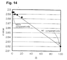
- Fig. 14 shows correlation between d values of the main crystal diffraction peak obtained through X-ray diffractometry and a values ( a : variable in the above compositional formula of the dielectric ceramic material of the present invention).
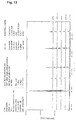
- Figs. 12 and 13 show no diffraction peak at 31.69°, which would be attributable to a phase containing M and Ta when the phase is isolated from a main crystal phase of the BZCN component.
- Fig. 13 shows enlarged diffraction peak patterns shown in Fig. 13, diffraction peaks of dielectric ceramic materials containing the MT component shift to the higher angle side as increase in the MT component content, as compared with diffraction peaks of the main crystal phase formed solely of the BZCN component.
- Fig. 14 shows a proportional relationship between a values and d values.
- Example 1 The procedure of Example 1 was repeated, except that manganese oxide (MnO 2 ) powder (purity 95%) and tungsten oxide (WO 3 ) powder (purity 99.8% or higher) were added to the raw material described in Example 1, to thereby yield sintered compact Nos. 1 to 21 having compositions shown in Table 5. Dielectric characteristics of these sintered compact Nos. 1 to 21 were evaluated in a manner similar to that of Example 1. The results are shown in Table 6. In Table 6, the symbol "*" denotes that the Mn content and the W content fall outside the ranges of the present invention.
- Figs. 1 to 4 show correlation between a (i.e., (M+ Ta) content) and ⁇ r, the relationship between a and Q 0 , correlation between a and Q 0 ⁇ f 0 , and correlation between a and ⁇ f.
- a sample exhibiting most well-balanced dielectric characteristics was selected and the numerical data thereof are plotted.
- the dielectric ceramic materials of the present invention containing M and Ta exhibit enhanced ⁇ r, Q 0 , Q 0 ⁇ f 0 , and ⁇ f, regardless of the species of M.
- Q 0 , Q 0 ⁇ f 0 , and ⁇ f can be remarkably enhanced through incorporation of small amounts ( a ⁇ 2.5) of M and Ta.
- dielectric ceramic material samples of compositions A, F, and G were investigated in terms of correlation between firing temperature and ⁇ r, correlation between firing temperature and Q 0 , correlation between firing temperature and Q 0 ⁇ f 0 , and correlation between firing temperature and ⁇ f, and the results are shown in Figs. 5 to 8.
- K is particularly preferred as M, since well-balanced, excellent dielectric characteristics can be attained when the ceramic materials are produced at low firing temperature. Specifically, for a firing temperature of 1,450°C, when M is K, ⁇ r, Q 0 , and Q 0 ⁇ f 0 are remarkably increased as compared with the case where M is Na or Li, and the absolute value of ⁇ f is remarkably lowered.
- dielectric ceramic material samples of composition G were investigated in terms of correlation between v (Co (or Zn) content) and ⁇ r, correlation between v and Q 0 , and correlation between v and ⁇ f, and the results are shown in Figs. 9 to 11.
- ⁇ r and ⁇ f increase approximately in proportion to increase in v (i.e., increase in Zn content).
- Table 6 shows that samples Nos. 1-5 containing Mn in an amount of 0.02-3 weight % as MnO 2 exhibit Q 0 ⁇ f 0 at 25°C of 48,000 GHz or higher, Q 0 ⁇ f 0 at 125°C of 38,000 GHz or higher, and percent maintenance as high as 74% or more.
- sample Nos. 8-11 containing W in an amount of 0.02-4.5 weight % as WO 3 show Q 0 ⁇ f 0 at 25°C of 32,000 GHz or higher, Q 0 ⁇ f 0 at 125°C of 25,000 GHz or higher, and percent maintenance as high as 72% or more.
- dielectric ceramic materials containing Mn in an amount of 0.02-3 weight % as MnO 2 or those containing W in an amount of 0.02-4.5 weight % as WO 3 exhibit more excellent dielectric characteristics and can attain excellent percent maintenance of Q value measured at high temperature with respect to that measured at room temperature.
- dielectric ceramic material Nos. 16, 18, and 20 containing Mn in an amount of at least 0.02 weight % (as oxide) exhibit high percent maintenance
- dielectric ceramic material Nos. 17, 19, and 21 having an Mn content less than 0.02 weight % exhibit a decreased Q 0 ⁇ f 0 and a decreased percent maintenance.
- v preferably falls within a range of 0.4 ⁇ v ⁇ 0.8 and a preferably falls within a range of 1 ⁇ a ⁇ 11. More preferably, v falls within a range of 0.4 ⁇ v ⁇ 0.7, and a falls within a range of 2 ⁇ a ⁇ 8. Particularly preferably, v falls within a range of 0.4 ⁇ v ⁇ 0.6, and a falls within a range of 2 ⁇ a ⁇ 6.
- the Mn content is preferably 0.02-3 weight % as MnO 2
- the W content is preferably 0.02-4.5 weight % as WO 3 .
- any elements may be incorporated in certain amounts so long as various dielectric characteristics of the ceramic materials are not impaired.
- additional elements include Mn, Mg, Fe, W, and B.
- novel dielectric ceramic materials in particular, dielectric ceramic materials exhibiting a small dielectric loss and a small absolute value of temperature coefficient of resonance frequency.
- dielectric ceramic materials can be produced through firing at low temperature. According to the present invention, high percent maintenance of Q value measured at high temperature with respect to that measured at room temperature can be attained.
Landscapes
- Chemical & Material Sciences (AREA)
- Engineering & Computer Science (AREA)
- Organic Chemistry (AREA)
- Ceramic Engineering (AREA)
- Manufacturing & Machinery (AREA)
- Inorganic Chemistry (AREA)
- Materials Engineering (AREA)
- Structural Engineering (AREA)
- Physics & Mathematics (AREA)
- Thermal Sciences (AREA)
- Compositions Of Oxide Ceramics (AREA)
- Inorganic Insulating Materials (AREA)
Abstract
Description
- This invention relates to a dielectric ceramic material and, more particularly to a ceramic material exhibiting dielectric characteristics; i.e., small dielectric loss and a small absolute value of temperature coefficient of resonance frequency, and to a dielectric ceramic material which can maintain a high percent maintenance of unloaded quality coefficient as expressed by percentage of unloaded quality coefficient measured at high temperature with respect to that measured at room temperature. The dielectric ceramic material of the invention may be employed in dielectric resonators and band-pass filters for use in a high-frequency region such as the microwave region or the milliwave region.
- Conventionally, a variety of compositions of dielectric ceramic materials have been investigated with a view to using the ceramic materials in the high-frequency region, such as the microwave region or the milliwave region, where dielectric characteristics such as a large relative dielectric constant, a small dielectric loss and a small absolute value of temperature coefficient of resonance frequency are required. In relation to such dielectric ceramic materials, Japanese Patent Publication (kokoku) Nos. 2-53884 and 4-321 and other publications describe dielectric ceramic materials having a BaNbO3 component. The Ba(Zn, Nb) dielectric materials described in the above publications exhibit excellent characteristics; i.e., a high unloaded quality coefficient and a small temperature coefficient of resonance frequency.
- However, those Ba(Zn, Nb) dielectric materials do not necessarily exhibit a satisfactory percentage maintenance of unloaded quality coefficient as expressed by percentage of unloaded quality coefficient measured at high temperature (approximately 125°C) with respect to that measured at room temperature (approximately 25°C). Therefore, when these dielectric ceramic materials are used in dielectric resonators and other apparatus, dielectric loss at high frequency problematically increases. In order to overcome this problem, researchers have pursued the development of dielectric ceramic materials which exhibit better dielectric characteristics and smaller temperature dependency of resonance frequency and maintain a high percentage maintenance of Q value as expressed by percentage of Q value measured at high temperature with respect to that measured at room temperature.
- The present invention seeks to provide a dielectric ceramic material which can attain a large unloaded quality coefficient and a small absolute value of temperature coefficient of resonance frequency as compared with conventional dielectric ceramic materials containing a BaNbO3 component and which allows wide-range selection of dielectric characteristics.
- The present invention provides a dielectric ceramic material comprising Ba, Nb, and Ta; at least one of Zn and Co; and at least one species selected from K, Na and Li, the ceramic material being represented by the following compositional formula:
- The present invention provides also a method for producing such a dielectric ceramic material which comprises mixing raw material powders such that molar proportions of component metals satisfy simultaneously the relationships specified above; molding the resultant mixture powder thereby to yield a compact; and firing the compact.
- The present invention provides further a dielectric ceramic material as specified above containing additionally Mn or W, wherein the amount of Mn is 0.02-3 weight % as MnO2 and the amount of W is 0.02-4.5 weight % as WO3.
- Through incorporation of M and Ta into the ceramic material, there can be obtained a dielectric ceramic material exhibiting a large unloaded quality coefficient (referred to simply as "Q0") as compared with a dielectric ceramic material containing no M or Ta. In such a case, even though the amounts of M or Ta added are small, a remarkably large Q0 of the dielectric ceramic material containing M and Ta can be provided as compared with a dielectric ceramic material containing no M or Ta (see Figs. 2 and 3). Moreover, the resultant ceramic material shows quite unexpected behavior; the Q0 shows its peak (maximum) in the vicinity of a = 2.5. This effect is significantly remarkable when M is K or Na, and most remarkable when M is K.
- Through incorporation of M and Ta into the ceramic material, it is possible to produce a dielectric ceramic material exhibiting a small absolute temperature coefficient of resonance frequency (referred to simply as "τf"). In such a case, even though the amounts of M and Ta are small, a remarkably small absolute value of τf can be obtained as compared with a dielectric ceramic material containing no M or Ta (see Fig. 4). Moreover, the resultant ceramic material shows quite unexpected behavior; the τf shows its peak (minimum) at approximately a = 5. This effect is particularly remarkable when M is K or Li.
- Through incorporation of M and Ta into the ceramic material, the firing temperature during production of the dielectric ceramic material of the present invention can also be lowered. Particularly when M is K, a dielectric ceramic material exhibiting well-balanced dielectric characteristics, i.e., a large relative dielectric constant (referred to simply as "εr"), a large Q0, and a small absolute value of τf can be produced through firing at a low firing temperature (see Figs. 5 to 8).
- The value of "a" representing (M + Ta) content, satisfies the relationship 0.5 ≤ a ≤ 25. When a is less than 0.5, the effects commensurate with incorporation of M and Ta may be difficult to attain, whereas when a is in excess of 25, the ceramic material compact cannot maintain its shape during firing, possibly resulting in difficulty in production of dielectric ceramics. Although no particular limitation is imposed on the value of a so long as a falls within the above range, the range is preferably 1 ≤ a ≤ 20, more preferably 1 ≤ a ≤ 10, most preferably 2 ≤ a ≤ 8, from the viewpoint of the above effects.
- The value of "y" satisfies the relationship 0.5 ≤ y ≤ 2.5 (preferably 1.0 ≤ y ≤ 2.0). When y is less than 0.5, sufficient sintering tends to be difficult. When y is less than 0.5 or in excess of 2.5, the product of unloaded quality coefficient and resonance frequency (referred to as "Q0·f0") may be problematically insufficient.
- The value of "z" satisfies the relationship 0.8 ≤ z ≤ 1.2. When z falls within 0.9 ≤ z ≤ 1.1, Q0·f0 attains a particularly large value, which is preferable. In contrast, when z is less than 0.8 or in excess of 1.2, a sufficiently large Q0·f0 value may fail to be attained, which is disadvantageous.
- The dielectric ceramic material of the present invention contains at least one of Zn and Co. The absolute value of Q0 and that of τf can be controlled over a wide range through modification of the Zn content or the Co content. Particularly, increase in Zn content remarkably elevates Q0 (see Fig. 10). However, Q0 exhibits its peak value at a certain Zn content (or Co content) when the Zn content is varied. This unexpected feature is different from the behavior of εr (absolute value) and that of τf (see Figs. 9 and 11). In addition to elevating Q0, increase in Zn content can elevate εr (see Fig. 9) and reduce the absolute value of τf (see Fig. 11).
- The value of "v" representing Zn content, can be modified within the range of 0 ≤ v ≤ 1. Although no particular limitation is imposed on v, a preferred range is 0.3 ≤ v ≤ 1, in that all dielectric characteristics can be enhanced. A range of 0.4 ≤ v ≤ 0.8 is more preferred, in that Q0 can be maintained at a high level. A range of 0.4 ≤ v ≤ 0.75 is particularly preferred, in that well-balanced dielectric properties; i.e., a large Q0 and a small absolute value of τf, can be attained. Needless to say, "1-v" representing Co content, can also be modified within a range of 0 ≤ 1-v ≤ 1.
- The value of "u" satisfies the relationship 0.98 ≤ u ≤ 1.03, preferably 0.99 ≤ u ≤ 1.02. When u is less than 0.98 or in excess of 1.03, a sufficiently large Q0·f0 value may fail to be attained, which is disadvantageous. When u is in excess of 1.03, satisfactory sintering tends to be difficult to attain.
- The value of "w" satisfies the relationship 0.274 ≤ w ≤ 0.374, preferably 0.294 ≤ w ≤ 0.354. When w is less than 0.274 or in excess of 0.374, a sufficiently large Q0·f0 value may fail to be attained, which is disadvantageous.
- The value of "x" satisfies the relationship 0.646 ≤ x ≤ 0.696, preferably 0.656 ≤ x ≤ 0.686. When x is less than 0.646 or in excess of 0.696, a sufficiently large Q0·f0 value may fail to be attained, which is disadvantageous.
- The value of "δ1" or "δ2" generally equals an equivalent value with respect to the metal species involved. However, the value is not particularly fixed to the equivalent value so long as the desired dielectric characteristics are not impaired. For example, δ1 falls within a range of 2.9 ≤ δ1 ≤ 3.1, and δ2 falls within a range of 2.5 ≤ δ2 ≤ 4.
- The compositional formula of the dielectric ceramic material is represented by two terms, i.e., [Bau{(ZnvCo1-v)wNbx}Oδ1] (referred to simply as "BZCN component") and [MyTazOδ2] (referred to simply as "MT component"). However, in the dielectric ceramic material, the BZCN component and the MT component form a solid solution having a single composition. Formation of the solid solution is confirmed by failure to observe an intrinsic diffraction peak (31.69°) attributable to the MT component in an X-ray diffraction chart (see Fig. 13); diffraction peaks of a dielectric ceramic material containing the MT component shifting on the higher angle side as compared with diffraction peaks of a BZCN dielectric ceramic material (see Fig. 13); and observation of approximately proportional correlation between the MT component content a and d values (see Fig. 14).
- Therefore, according to the present invention, there can be obtained a large Q0 and a small absolute value of τf, which have not been satisfactorily attained by a dielectric ceramic material formed solely of a BZCN component, and well-balanced dielectric characteristics including these two properties can be provided.
- In addition to containing these components, the dielectric ceramic material of the present invention may further contain Mn or W. The Mn content or W content is such that, with respect to 100 parts by weight of the following composition (100-a)[Bau{(ZnvCo1-v)wNbx}Oδ1]-a[MyTazOδ2] (in which M a, u, v, w, x, y and z are as defined above) Mn is present in an amount of 0.02-3 weight % as MnO2, preferably 0.02-2.5 weight %, more preferably 0.02-2 weight %, particularly preferably 0.02-1.5 weight %, most preferably 0.05-1.5 weight %, or W is present in an amount of 0.02-4.5 weight % as WO3, preferably 0.02-4 weight %, more preferably 0.02-3.5 weight %, particularly preferably 0.02-3 weight %, most preferably 0.03-2 weight %. Control of the Mn content or W content (as MnO2 or WO3) to 0.02 weight % or higher is preferred, since deterioration of percent maintenance of Q value at high temperature can be prevented, and a higher Q value can be maintained. Control of the Mn content (as MnO2) to 3 weight % or less or the W content (as WO3) to 4.5 weight % or less is preferred, since deterioration of percent maintenance of Q value at room temperature and high temperatures can be prevented, the absolute value of τf can be reduced, and more excellent dielectric characteristics can be maintained.
- The Mn or W is incorporated typically in oxide form such as MnO2 or WO3 and resides in the dielectric ceramic material. However, the form is not limited to oxide, and other forms such as salts, halides and alkoxides may be employed so long as Mn or W can be incorporated into the dielectric ceramic material.
- According to the present invention, when a preferred compositional range and preferred firing temperature are employed, the following characteristics can be attained: εr of 32-37 (preferably 32-36, more preferably 33-35); Q0 as measured in TE011 mode of 7,000-23,000 (preferably 9,000-22,000, more preferably 10,000-21,000); Q0·f0 as measured in TE01δ mode of 7,000-63,000 GHz (preferably 10,000-60,000 GHz, more preferably 20,000-60,000 GHz); and temperature coefficient of resonance frequency (τf) of -12 to 34 ppm/°C (preferably -5 to 32 ppm/°C, more preferably -2 to 15 ppm/°C).
- When M is K and a is 1-10, the following characteristics can be attained: εr of 32-37 (preferably 32-36, more preferably 33-35); Q0 as measured in TE011 mode of 7,000-23,000 (preferably 9,000-22,000, more preferably 10,000-21,000); Q0·f0 as measured in TE01δ mode of 7,000-63,000 GHz (preferably 10,000-60,000 GHz, more preferably 20,000-60,000 GHz); and temperature coefficient of resonance frequency (τf) of -12 to 34 ppm/°C (preferably -5 to 32 ppm/°C, more preferably -2 to 15 ppm/°C).
- When M is K and a is 2-8, the following characteristics can be attained: εr of 32-37 (preferably 32-36, more preferably 33-35); Q0 as measured in TE011 mode of 10,000-23,000 (preferably 11,000-22,000, more preferably 12,000-21,000); Q0·f0 as measured in TE01δ mode of 20,000-63,000 GHz (preferably 30,000-60,000 GHz, more preferably 35,000-60,000 GHz); and temperature coefficient of resonance frequency (τf) of -12 to 34 ppm/°C (preferably -5 to 32 ppm/°C, more preferably -2 to 15 ppm/°C).
- When M is K, a is 2-8, and v is 0.2-0.8, the following characteristics can be attained: εr of 32-37 (preferably 32-36, more preferably 33-35); Q0 as measured in TE011 mode of 10,000-23,000 (preferably 11,000-22,000, more preferably 12,000-21,000); Q0·f0 as measured in TE01δ mode of 20,000-63,000 GHz (preferably 30,000-60,000 GHz, more preferably 35,000-60,000 GHz); and temperature coefficient of resonance frequency (τf) of -12 to 34 ppm/°C (preferably -5 to 32 ppm/°C, more preferably -2 to 15 ppm/°C).
- When the dielectric ceramic material further contains Mn or W, there can be attained a percent maintenance of Q value as expressed by percentage of Q value measured at 125°C with respect to that measured at 25°C of 70% or higher, preferably 72% or higher, more preferably 74% or higher, particularly preferably 75% or higher. The percent maintenance (%) is calculated on the basis of the following equation:
- The above remarkably excellent dielectric characteristics can be provided by a dielectric ceramic material which has been produced through firing at 1,375-1,600°C, preferably 1,425-1,575°C.
- The dielectric characteristics (εr, Q0, and τf) were measured in the TE011 mode described below. The Q0·f0 was measured in the TE01δ mode described below. The reason for employing Q0·f0 is that Q0·f0 cancels the effect of inevitable variation (per measurement) of resonance frequency during measurement of dielectric characteristics. Through employment of Q0·f0, dielectric loss can be evaluated more accurately.
- The following Examples illustrate the invention. The Examples make reference to the accompanying drawings, in which:
- Fig. 1 is a plot showing the correlation between a and εr;
- Fig. 2 is a plot showing the correlation between a and Q0;
- Fig. 3 is a plot showing the correlation between a and Q0·f0;
- Fig. 4 is a plot showing the correlation between a and τf;
- Fig. 5 is a plot showing the correlation between firing temperature and εr;
- Fig. 6 is a plot showing the relationship between firing temperature and Q0;
- Fig. 7 is a plot showing the correlation between firing temperature and Q0·f0;
- Fig. 8 is a plot showing the correlation between firing temperature and τf;
- Fig. 9 is a plot showing the correlation between v and εr;
- Fig. 10 is a plot showing the correlation between v and Q0;
- Fig. 11. is a plot showing the correlation between v and τf;
- Fig. 12 is an X-ray diffraction spectrum of dielectric ceramic materials with increasing a;
- Fig. 13 is an enlarged portion of Fig. 12; and
- Fig. 14 is a plot showing the correlation between a values and d values obtained through X-ray diffractometry of the dielectric ceramic materials according to the present invention.
-
- Barium carbonate powder, zirconium oxide powder, cobalt oxide (CoO) powder, niobium oxide (Nb2O5) powder, tantalum oxide (Ta2O5) powder and potassium carbonate powder, all commercial products and having a purity of 99.9% or higher, were weighed in predetermined amounts in accordance with compositional formulas corresponding to the experiments shown in Tables 1 and 2, wherein A to J appearing in the column of "Experiment No." represent types of compositions, and 1 to 6 denote the corresponding firing temperatures. Each mixture was dry-mixed for 20-30 minutes in a mixer and subjected to primary pulverization in a vibration mill. Primary pulverization was performed for four hours using alumina grinding balls.
- The resultant powder was calcined in air at 1,100-1,300°C for two hours, to thereby yield a calcined powder. The calcined powder was mixed with an appropriate amount of an organic binder and water, and the mixture was subjected to secondary pulverization for 10-15 hours in a trommel pulverizer. The pulverized product was freeze-dried and granulated, and granules having a particle size of 40 to 200 mesh were separated from the granulated product by use of sieves. The granules were molded in a press machine into compacts (diameter: 19 mm, height 11 mm). The compacts were debindered at 500°C for four hours, and fired in air at the temperature shown in Table 1 or 2 for three hours, to thereby yield sintered compacts having compositions A to J.
- Compacts having composition I (containing no M or Ta) and fired at 1,400°C or 1,450°C (I-1 and I-2) failed to produce sintered dielectric ceramic material, since the firing temperatures were insufficient to achieve sintering. Compacts having composition D (containing M and Ta at a = 20) and fired at 1,500°C or higher (D-3) melted during the course of firing, thereby failing to produce a sintered ceramic material, since the firing temperature was excessively high. Similarly, compacts having composition E (containing M and Ta in amounts falling outside the scope of the invention) and fired at 1,400°C melted during the course of firing, thereby failing to produce sintered ceramic material.
- Although compacts having composition A (containing M and Ta at a = 2.5) and fired at 1,400°C (A-1) could not be sufficiently sintered, those fired at 1,450-1,600°C (A-2 to A-6) were able to produce dielectric ceramic materials. Compacts having composition B (containing M and Ta at a = 5) and fired at 1,400°C (B-1) were also able to produce dielectric ceramic materials.
- The results indicate that incorporation of M and Ta lowers the firing temperature, and that the firing temperature can be lowered as the amounts of M and Ta increase within the range of a = 2.5-20.
Experiment No. Compositional formula (100-a)[Bau[(ZnvCo1-v)wNbx]Oδ1]-a[MyTazOδ2] Firing temp. (°C) *A-1 97.5[Ba1.01[(Zn0.5Co0.5)0.324Nb0.666]Oδ1]-2.5[K1.5TaOδ2] 1,400 A-2 1,450 A-3 1,500 A-4 1,525 A-5 1,550 A-6 1,600 B-1 95[Ba1.01[(Zn0.5Co0.5)0.324Nb0.666]Oδ1]-5[K1.5TaOδ2] 1,400 B-2 1,450 B-3 1,500 B-5 1,550 C-1 90[Ba1.01[(Zn0.5Co0.5)0.324Nb0.666]Oδ1]-10[K1.5TaOδ2] 1,400 D-2 80[Ba1.01[(Zn0.5Co0.5)0.324Nb0.666]Oδ1]-20[K1.5TaOδ2] 1,450 *D-3 1,500 *E-1 *E-1 50[Ba1.01[(Zn0.5Co0.5)0.324Nb0.666]Oδ1]-50[K1.5TaOδ2] 1,400 F-1 97.5[Ba1.01[(Zn0.5Co0.5)0.324Nb0.666]Oδ1]-2.5[Na1.5TaOδ2] 1,400 F-2 1,450 F-3 1,500 F-5 1,550 F-6 1,600 Experiment No. Compositional formula (100-a)[Bau[(ZnvCo1-v)wNbx]Oδ1]-a[MyTazOδ2] Firing temp. (°C) G-1 97.5[Ba1.01[(Zn0.5Co0.5)0.324Nb0.666]Oδ1]-2.5[Li1.5TaOδ2] 1,400 G-3 1,500 G-5 1,550 G-6 1,600 H-1 97.5[Ba1.01[Co0.324Nb0.666]Oδ1]-2.5[K1.5TaOδ2] 1,525 H-2 97.5[Ba1.01[(Zn0.25Co0.75)0.324Nb0.666]Oδ1]-2.5[K1.5TaOδ2] H-3 97.5[Ba1.01[(Zn0.75Co0.25)0.324Nb0.666]Oδ1]-2.5[K1.5TaOδ2] H-4 97.5[Ba1.01[Zn0.324Nb0.666]Oδ1]-2.5[K1.5TaOδ2] *I-1 95[Ba1.01[(Zn0.5Co0.5)0.324Nb0.666]Oδ2] 1,400 *I-2 1,450 *I-3 1,500 *I-5 1,550 *I-6 1,600 *J-1 50[Ba1.01[(Zn0.5Co0.5)0.324Nb0.666]Oδ1]-50[K1.5TaOδ2] 1,400 - Each of the dielectric ceramic materials produced in [1] (Experiment Nos. I-3 (a = 0), A-4 (a = 2.5), B-2 (a = 5), C-1 (a = 10), and D-2 (a = 20)) was pulverized in a mortar, and the resultant powder was subjected to X-ray diffractometry (CuKα). Fig. 12 and 13 show multiply recorded diffraction patterns. Fig. 12 shows a scanned angle range of 20-70°, and Fig. 13 is an enlarged portion of Fig. 12 showing diffraction peaks of a main crystal phase confirmed in the vicinity of 31°.
- Fig. 14 shows correlation between d values of the main crystal diffraction peak obtained through X-ray diffractometry and a values (a: variable in the above compositional formula of the dielectric ceramic material of the present invention).
- Figs. 12 and 13 show no diffraction peak at 31.69°, which would be attributable to a phase containing M and Ta when the phase is isolated from a main crystal phase of the BZCN component. In enlarged diffraction peak patterns shown in Fig. 13, diffraction peaks of dielectric ceramic materials containing the MT component shift to the higher angle side as increase in the MT component content, as compared with diffraction peaks of the main crystal phase formed solely of the BZCN component. Fig. 14 shows a proportional relationship between a values and d values. These results indicate that the BZCN component and the MT component form a solid solution in which the two components are mutually dissolved.
- All sintered ceramic compacts that had been produced in [1] were polished, to thereby provide columnar ceramic pieces (diameter: 16 mm, height: 8 mm). Each of the polished ceramic pieces was evaluated in terms of εr, Q0, and τf (temperature range: 25-80°C) through a parallel-conductor-plates dielectric resonator method in TE011 mode over 3-5 GHz The results are shown in Tables 3 and 4. Q0 and f0 of the polished ceramic pieces were also measured through a dielectric resonator method in TE01δ mode over 3-4 GHz. Tables 3 and 4 also show values of the product f0·Q0.
Experiment No. Composition type Dielectric characteristics Specific gravity εr TE011 mode Q0 TE01δ mode f0·Q0 (GHz) τf (ppm/°C) *A-1 KTa-2.5 Unsintered A-2 32.9 19,323 44,330 8.99 6.280 A-3 34.6 19,202 52,580 8.95 6.343 A-4 34.1 20,588 58,742 8.85 6.294 A-5 33.8 19,922 44,629 8.24 6.250 A-6 32.6 8,545.5 8,557 10.53 6.144 B-1 KTa-5.0 23.6 13,698 20,020 11.29 5.432 B-2 34.6 20,237 52,473 7.49 6.327 B-3 33.5 6,936 6,517 12.82 6.095 B-5 32.9 905 703 32.41 5.927 C-1 KTa-10 32.5 18,927 42,109 15.31 5.934 D-2 KTa-20 38.4 10,265 17,168 35.55 6.372 *D-3 Dissolved *E-1 Dissolved F-1 F-2 F-3 F-5 F-6 NaTa-2.5 23.5 9,491 6,025 29.97 4.987 26.6 7,965 2,722 33.62 6.011 34.8 13,424 23,498 26.18 6.168 34.0 16,413 33,588 17.24 6.097 33.0 10,566 13,047 15.39 6.036 Experiment No. Composition type Dielectric characteristics Specific gravity εr TE011 mode Q0 TE01δ mode f0·Q0 (GHz) τf (ppm/°C) G-1 LiTa-2.5 21.2 9,527 4,737 14.44 4.482 G-3 34.1 8,428 11,227 8.53 6.324 G-5 32.2 2,934 2,494 8.32 6.012 G-6 31.6 2,142 1,843 13.15 5.830 H-1 Co-1 30.9 4,297 15,308 -11.5 6.253 H-2 Co-0.75 32.5 10,290 32,084 -1.1 6.287 H-3 Co-0.25 35.6 16,043 66,538 18.5 6.260 H-4 Co-0 36.9 13,027 65,391 31.6 6.173 *I-1 *I-2 No KTa Unsintered *I-3 29.0 5,120 6,035 20.89 5.515 *I-5 33.1 2,988 2,777 18.67 5.957 *I-6 33.3 6,314 6,419 19.02 5.972 *J-1 KTa-50 Dissolved (sintering impossible) - The procedure of Example 1 was repeated, except that manganese oxide (MnO2) powder (purity 95%) and tungsten oxide (WO3) powder (purity 99.8% or higher) were added to the raw material described in Example 1, to thereby yield sintered compact Nos. 1 to 21 having compositions shown in Table 5. Dielectric characteristics of these sintered compact Nos. 1 to 21 were evaluated in a manner similar to that of Example 1. The results are shown in Table 6. In Table 6, the symbol "*" denotes that the Mn content and the W content fall outside the ranges of the present invention.
Experiment No. Compositional formula (100-a)[Bau[(ZnvCo1-v)wNbx]Oδ1]-a[MyTazOδ2] Amount of Mn, W added (weight%) 1 97.5[Ba1.01[(Zn0.5Co0.5)0.326Nb0.666]O3]-2.5[K1.5TaO3] Mn 0.05 2 Mn 0.10 3 Mn 0.25 4 Mn 0.8 5 Mn 1.3 *6 Mn 0.01 *7 Mn 3.5 8 W 0.05 9 W 0.10 10 W 0.80 11 W 1.5 *12 W 0.01 *13 W 5.0 *14 None 15 95[Ba1.01[(Zn0.5Co0.5)0.324Nb0.666]O3]-5[K1.5TaO3] Mn 0.05 16 97.5[Ba1.01[(Zn0.5Co0.5)0.324Nb0.666]O3]-2.5[Na1.5TaO3] Mn 0.05 *17 None 18 97.5[Ba1.01[Co0.324Nb0.666]O3]-2.5[K1.5TaO3] Mn 0.10 *19 None 20 97.5[Ba1.01[Zn0.324Nb0.666]O3]-2.5[K1.5TaO3] Mn 0.15 *21 Mn 0.01 Experiment No. εr TE011 mode f0·Q0 (GHz) TE01δ mode f0·Q0 (GHz) Percent maintenance (%) τf (ppm/°C) 25°C 125° C 1 34.1 20,590 59,240 43,720 73.8 8.93 2 34.1 21,000 60,584 46,165 76.2 9.24 3 34.4 20,890 56,221 42,390 75.4 8.72 4 34.5 19,620 52,104 38,870 74.6 9.11 5 35.2 16,600 48,774 38,239 78.4 8.72 *6 34.1 20,600 57,202 37,410 65.4 8.61 *7 34.8 10,500 18,624 14,545 78.1 12.11 8 34.1 20,420 57,733 41,799 72.4 8.64 9 34.2 20,930 61,425 47,973 78.1 8.84 10 34.3 21,150 58,611 45,541 77.7 9.12 11 35.6 18,600 32,614 25,896 79.4 8.72 *12 34.1 20,400 57,912 37,179 64.2 8.84 *13 36.0 9,640 14,272 11,303 79.2 11.21 *14 34.1 20,588 58,742 38,299 65.2 8.85 15 32.5 19,200 43,105 31,984 74.2 15.74 16 34.1 17,200 33,704 25,312 75.1 16.41 *17 34.0 16,413 33,588 21,228 63.2 17.24 18 31.6 5,240 9,440 7,288 77.2 -8.41 *19 30.9 4,297 8,962 6,130 68.4 -11.5 20 36.7 14,620 32,200 25,245 78.4 30.1 *21 36.9 13,027 17,240 11,068 64.2 31.6 - Effects of incorporation of M and Ta can be confirmed from Figs. 1 to 4, which show correlation between a (i.e., (M+ Ta) content) and εr, the relationship between a and Q0, correlation between a and Q0·f0, and correlation between a and τf. In connection with Figs. 1 to 4, among dielectric ceramic material samples having the same composition produced at different firing temperatures, a sample exhibiting most well-balanced dielectric characteristics was selected and the numerical data thereof are plotted.
- As is clear from Figs. 1 to 4, as compared with dielectric ceramic materials containing no M or Ta, the dielectric ceramic materials of the present invention containing M and Ta exhibit enhanced εr, Q0, Q0·f0, and τf, regardless of the species of M. In particular, Q0, Q0·f0, and τf can be remarkably enhanced through incorporation of small amounts (a ≤ 2.5) of M and Ta. Q0 and Q0·f0 exhibit their maximum values at a = 2.5. Q0 is as high as 10,000 or more at a = 1-20, and Q0·f0, is as high as 40,000 GHz or more at a = 1-11. τf exhibits its minimum at a = 5 and is as low as 8-15[ppm/°C ] at a = 2-10.
- When M is K or Na, the effect of enhancing Q0 and Q0·f0 is remarkably great. This effect is particularly enhanced when M is K. Both K and Li exert a great effect of enhancing τf (i.e., lowering the absolute value of τf).
- In order to confirm effects of the type of M on correlation between firing temperature and dielectric characteristics, dielectric ceramic material samples of compositions A, F, and G were investigated in terms of correlation between firing temperature and εr, correlation between firing temperature and Q0, correlation between firing temperature and Q0·f0, and correlation between firing temperature and τf, and the results are shown in Figs. 5 to 8.
- As is clear from Figs. 5 and 6, K is particularly preferred as M, since well-balanced, excellent dielectric characteristics can be attained when the ceramic materials are produced at low firing temperature. Specifically, for a firing temperature of 1,450°C, when M is K, εr, Q0, and Q0·f0 are remarkably increased as compared with the case where M is Na or Li, and the absolute value of τf is remarkably lowered.
- In order to confirm effects of incorporation of Co and Zn, dielectric ceramic material samples of composition G were investigated in terms of correlation between v (Co (or Zn) content) and εr, correlation between v and Q0, and correlation between v and τf, and the results are shown in Figs. 9 to 11.
- As shown in Figs. 9 to 11, εr and τf increase approximately in proportion to increase in v (i.e., increase in Zn content). Q0 exhibits unexpected behavior; i.e., increases steeply at v = approximately 0.5, remains approximately constant around v = 0.5-0.8, and gradually decreases at v ≥0.8. Accordingly, in order to attain well-balanced dielectric characteristics, v is preferably controlled to 0.8 or less, particularly preferably v = 0.4-0.8, in that Q0 is as high as at least 10,000.
- Table 6 shows that samples Nos. 1-5 containing Mn in an amount of 0.02-3 weight % as MnO2 exhibit Q0·f0 at 25°C of 48,000 GHz or higher, Q0·f0 at 125°C of 38,000 GHz or higher, and percent maintenance as high as 74% or more. Similarly, sample Nos. 8-11 containing W in an amount of 0.02-4.5 weight % as WO3 show Q0·f0 at 25°C of 32,000 GHz or higher, Q0·f0 at 125°C of 25,000 GHz or higher, and percent maintenance as high as 72% or more. In addition, samples Nos. 1 to 5 and Nos. 8-11 exhibit τf as small as 9.5 or less. These results indicate that dielectric ceramic materials containing Mn in an amount of 0.02-3 weight % as MnO2 or those containing W in an amount of 0.02-4.5 weight % as WO3 exhibit more excellent dielectric characteristics and can attain excellent percent maintenance of Q value measured at high temperature with respect to that measured at room temperature.
- Samples Nos. 6, 12, and 14, all having the same composition of the predominant component and containing Mn in an amount of 0.01 weight % as MnO2, W in an amount of 0.01 weight % as WO3, and no Mn or W, exhibit Q0·f0 at 25°C of 57,000 GHz or higher, and Q0·f0 at 125°C of 37,000 GHz or higher, but exhibit a low percent maintenance of approximately 64-65%. Sample No. 7 containing Mn in an amount of 3.5 weight % as MnO2 and sample No. 13 containing W in an amount of 5.0 weight % as WO3, exhibit high percent maintenance of 78.1% and 79.2%, respectively, but exhibit considerably low Q0·f0 values; i.e., Q0·f0 at 25°C of 19,000 GHz or less, Q0·f0 at 125°C of 15,000 GHz or less, and τf of 11 or greater.
- The above tendency is also recognized in pairs of samples; specifically, Nos. 16 and 17, Nos. 18 and 19, and Nos. 20 and 21, each pair of samples having the same composition of the predominant component. Namely, dielectric ceramic material Nos. 16, 18, and 20 containing Mn in an amount of at least 0.02 weight % (as oxide) exhibit high percent maintenance, whereas dielectric ceramic material Nos. 17, 19, and 21 having an Mn content less than 0.02 weight % exhibit a decreased Q0·f0 and a decreased percent maintenance.
- As described above, in order to fully attain the effects of incorporation of M and Ta simultaneously with those of Co and Zn, v preferably falls within a range of 0.4 ≤ v ≤ 0.8 and a preferably falls within a range of 1 ≤ a ≤ 11. More preferably, v falls within a range of 0.4 ≤ v ≤ 0.7, and a falls within a range of 2 ≤ a ≤ 8. Particularly preferably, v falls within a range of 0.4 ≤ v ≤ 0.6, and a falls within a range of 2 ≤ a ≤ 6.
- When Mn or W is incorporated, the Mn content is preferably 0.02-3 weight % as MnO2, and the W content is preferably 0.02-4.5 weight % as WO3.
- Other than Ba, Zn, Co, Nb, Ta, K, Na, Li and O any elements may be incorporated in certain amounts so long as various dielectric characteristics of the ceramic materials are not impaired. No particular limitation is imposed on the additional elements, and examples include Mn, Mg, Fe, W, and B.
- According to the present invention, there are provided novel dielectric ceramic materials, in particular, dielectric ceramic materials exhibiting a small dielectric loss and a small absolute value of temperature coefficient of resonance frequency. In addition, such dielectric ceramic materials can be produced through firing at low temperature. According to the present invention, high percent maintenance of Q value measured at high temperature with respect to that measured at room temperature can be attained.
Claims (7)
- A dielectric ceramic material comprising Ba, Nb, and Ta; at least one of Zn and Co; and at least one species selected from K, Na, and Li, the ceramic material being represented by the following compositional formula:
- A dielectric ceramic material according to claim 1, wherein M is K.
- A dielectric ceramic material according to claim 1 or claim 2, wherein y and z satisfy the relationships 1.0 ≤ y < 2.0 and 0.9 ≤ z < 1.1.
- A dielectric ceramic material according to any one of claims 1 to 3, wherein a satisfies the relationship 1 ≤ a ≤ 10.
- A dielectric ceramic material according to any one of claims 1 to 4 containing also Mn or W, in amounts of 0.02-3 weight % Mn as MnO2 and 0.02-4.5 weight % W as WO3, based on 100 parts by weight of the material having the compositional formula specified in claim 1.
- A dielectric ceramic material according to claim 5, having a percent maintenance of unloaded quality coefficient as expressed by percentage of unloaded quality coefficient measured at 125°C with respect to that measured at 25°C, of at least 70%.
- A method for producing a dielectric ceramic material according to any one of claims 1 to 6, which comprises mixing together raw material powders such that the molar proportions of the component metals satisfy the relationships specified in any one of claims 1 to 5; molding the resultant mixture to thereby yield a compact; and firing the compact.
Applications Claiming Priority (4)
| Application Number | Priority Date | Filing Date | Title |
|---|---|---|---|
| JP2001215941 | 2001-07-16 | ||
| JP2001215941 | 2001-07-16 | ||
| JP2001329618 | 2001-10-26 | ||
| JP2001329618 | 2001-10-26 |
Publications (2)
| Publication Number | Publication Date |
|---|---|
| EP1277713A1 true EP1277713A1 (en) | 2003-01-22 |
| EP1277713B1 EP1277713B1 (en) | 2006-10-11 |
Family
ID=26618825
Family Applications (1)
| Application Number | Title | Priority Date | Filing Date |
|---|---|---|---|
| EP02254918A Expired - Lifetime EP1277713B1 (en) | 2001-07-16 | 2002-07-12 | Dielectric ceramic material comprising Ba, Nb, Ta, Zn, Co and at least one of K, Na and Li |
Country Status (5)
| Country | Link |
|---|---|
| US (1) | US6995106B2 (en) |
| EP (1) | EP1277713B1 (en) |
| KR (1) | KR100843012B1 (en) |
| CN (1) | CN1251993C (en) |
| DE (1) | DE60215263D1 (en) |
Families Citing this family (3)
| Publication number | Priority date | Publication date | Assignee | Title |
|---|---|---|---|---|
| KR100595917B1 (en) * | 1998-01-26 | 2006-07-05 | 웨인 웨스터만 | Method and apparatus for integrating manual input |
| JPWO2012029956A1 (en) * | 2010-09-02 | 2013-10-31 | 日本特殊陶業株式会社 | Dielectric porcelain, manufacturing method thereof, and dielectric resonator |
| CN107266074B (en) * | 2017-06-21 | 2019-09-03 | 广东国华新材料科技股份有限公司 | A kind of microwave ceramic material and preparation method thereof |
Citations (6)
| Publication number | Priority date | Publication date | Assignee | Title |
|---|---|---|---|---|
| JPH09169567A (en) * | 1995-12-19 | 1997-06-30 | Kyocera Corp | Dielectric porcelain composition for high frequency |
| JPH09227230A (en) * | 1996-02-28 | 1997-09-02 | Kyocera Corp | Dielectric porcelain composition for high-frequency |
| JPH09315863A (en) * | 1996-05-29 | 1997-12-09 | Kyocera Corp | Dielectric ceramics composition and electronic parts |
| JPH1045471A (en) * | 1996-07-31 | 1998-02-17 | Kyocera Corp | Dielectric porcelain composition for high frequency |
| EP0838446A1 (en) * | 1996-10-25 | 1998-04-29 | Ngk Spark Plug Co., Ltd | A dielectric material, a method for producing the same and a dielectric resonator device comprising same |
| EP1205453A1 (en) * | 2000-01-31 | 2002-05-15 | Ngk Spark Plug Co., Ltd. | Dielectric porcelain composition and dielectric resonator using the same |
Family Cites Families (5)
| Publication number | Priority date | Publication date | Assignee | Title |
|---|---|---|---|---|
| US4889579A (en) | 1988-07-06 | 1989-12-26 | E. I. Du Pont De Nemours And Company | Process for adhering aramid polymers |
| JP2815028B2 (en) | 1989-09-21 | 1998-10-27 | 新日本製鐵株式会社 | Method for producing steel pipe having yield point elongation, low yield ratio and excellent low temperature toughness |
| JP3493316B2 (en) | 1999-01-14 | 2004-02-03 | 京セラ株式会社 | High frequency dielectric ceramic composition and dielectric resonator |
| KR100415757B1 (en) | 1999-01-14 | 2004-01-31 | 교오세라 가부시키가이샤 | Dielectric ceramic composition, method of preparing dielectric ceramic material, and dielectric resonator |
| JP2001141568A (en) | 1999-11-10 | 2001-05-25 | Ozaki Shoji | Comfortableness evaluating device for school uniform |
-
2002
- 2002-07-11 KR KR1020020040335A patent/KR100843012B1/en not_active IP Right Cessation
- 2002-07-12 DE DE60215263T patent/DE60215263D1/en not_active Expired - Lifetime
- 2002-07-12 EP EP02254918A patent/EP1277713B1/en not_active Expired - Lifetime
- 2002-07-15 CN CNB021407177A patent/CN1251993C/en not_active Expired - Fee Related
- 2002-07-15 US US10/194,941 patent/US6995106B2/en not_active Expired - Fee Related
Patent Citations (6)
| Publication number | Priority date | Publication date | Assignee | Title |
|---|---|---|---|---|
| JPH09169567A (en) * | 1995-12-19 | 1997-06-30 | Kyocera Corp | Dielectric porcelain composition for high frequency |
| JPH09227230A (en) * | 1996-02-28 | 1997-09-02 | Kyocera Corp | Dielectric porcelain composition for high-frequency |
| JPH09315863A (en) * | 1996-05-29 | 1997-12-09 | Kyocera Corp | Dielectric ceramics composition and electronic parts |
| JPH1045471A (en) * | 1996-07-31 | 1998-02-17 | Kyocera Corp | Dielectric porcelain composition for high frequency |
| EP0838446A1 (en) * | 1996-10-25 | 1998-04-29 | Ngk Spark Plug Co., Ltd | A dielectric material, a method for producing the same and a dielectric resonator device comprising same |
| EP1205453A1 (en) * | 2000-01-31 | 2002-05-15 | Ngk Spark Plug Co., Ltd. | Dielectric porcelain composition and dielectric resonator using the same |
Non-Patent Citations (4)
| Title |
|---|
| PATENT ABSTRACTS OF JAPAN vol. 1997, no. 10 31 October 1997 (1997-10-31) * |
| PATENT ABSTRACTS OF JAPAN vol. 1998, no. 01 30 January 1998 (1998-01-30) * |
| PATENT ABSTRACTS OF JAPAN vol. 1998, no. 04 31 March 1998 (1998-03-31) * |
| PATENT ABSTRACTS OF JAPAN vol. 1998, no. 06 30 April 1998 (1998-04-30) * |
Also Published As
| Publication number | Publication date |
|---|---|
| US20030109374A1 (en) | 2003-06-12 |
| KR100843012B1 (en) | 2008-07-01 |
| US6995106B2 (en) | 2006-02-07 |
| EP1277713B1 (en) | 2006-10-11 |
| DE60215263D1 (en) | 2006-11-23 |
| CN1398821A (en) | 2003-02-26 |
| CN1251993C (en) | 2006-04-19 |
| KR20030007129A (en) | 2003-01-23 |
Similar Documents
| Publication | Publication Date | Title |
|---|---|---|
| US6117806A (en) | Dielectric material, a method for producing the same and a dielectric resonator device comprising same | |
| EP0587140B1 (en) | Dielectric ceramic compositions and dielectric resonators | |
| EP1277713A1 (en) | Dielectric ceramic material comprising Ba, Nb, Ta and at least one of Zn and Co and and least one of K, Na and Li | |
| US20130162101A1 (en) | Dielectric sintered body, method for manufacturing same, and dielectric resonator | |
| KR20010109472A (en) | Dielectric porcelain, dielectric porcelain composition, method of manufacturing the same and dielectric resonator using the same | |
| US5256639A (en) | Dielectric ceramic composition | |
| JP2008266121A (en) | Dielectric porcelain composition and dielectric resonator | |
| EP0589441B1 (en) | Composition of dielectric ceramics | |
| US6242376B1 (en) | Dielectric ceramic composition | |
| US6645896B2 (en) | Dielectric ceramic composition for high frequency and dielectric resonator | |
| JP3598851B2 (en) | Dielectric ceramic composition, method of manufacturing the same, dielectric resonator and dielectric filter using the same | |
| JP4920853B2 (en) | Dielectric porcelain | |
| JP3605295B2 (en) | Dielectric ceramic composition and dielectric resonator using the same | |
| JP3376855B2 (en) | Dielectric ceramic composition, method of manufacturing the same, dielectric resonator and dielectric filter using the same | |
| JP3395577B2 (en) | Method of manufacturing dielectric ceramic electronic component | |
| EP1013624A2 (en) | High-frequency dielectric ceramic composition, dielectric resonator, dielectric filter, dielectric duplexer and communication device | |
| JP4688289B2 (en) | Dielectric porcelain and dielectric resonator using the same | |
| EP0882688A1 (en) | Microwave dielectric porcelain composition | |
| CN103038190A (en) | Dielectric ceramic and dielectric filter including same | |
| EP0881199A1 (en) | Dielectric ceramics | |
| EP0916631B1 (en) | Microwave dielectric porcelain composition | |
| JP3330024B2 (en) | High frequency dielectric ceramic composition | |
| JP4678569B2 (en) | Dielectric ceramic composition for electronic devices | |
| KR101118425B1 (en) | Dielectric ceramic composition for electronic device | |
| JP2002187771A (en) | Dielectric porcelain and dielectric resonator using the same |
Legal Events
| Date | Code | Title | Description |
|---|---|---|---|
| PUAI | Public reference made under article 153(3) epc to a published international application that has entered the european phase |
Free format text: ORIGINAL CODE: 0009012 |
|
| AK | Designated contracting states |
Kind code of ref document: A1 Designated state(s): AT BE BG CH CY CZ DE DK EE ES FI FR GB GR IE IT LI LU MC NL PT SE SK TR |
|
| AX | Request for extension of the european patent |
Free format text: AL;LT;LV;MK;RO;SI |
|
| 17P | Request for examination filed |
Effective date: 20030703 |
|
| AKX | Designation fees paid |
Designated state(s): DE FI FR GB IT SE |
|
| R17P | Request for examination filed (corrected) |
Effective date: 20030703 |
|
| RBV | Designated contracting states (corrected) |
Designated state(s): DE FI FR GB IT SE |
|
| 17Q | First examination report despatched |
Effective date: 20031002 |
|
| REG | Reference to a national code |
Ref country code: SE Ref legal event code: TRGR |
|
| GRAP | Despatch of communication of intention to grant a patent |
Free format text: ORIGINAL CODE: EPIDOSNIGR1 |
|
| RTI1 | Title (correction) |
Free format text: DIELECTRIC CERAMIC MATERIAL COMPRISING BA, NB, TA, ZN, CO AND AT LEAST ONE OF K, NA AND LI |
|
| GRAS | Grant fee paid |
Free format text: ORIGINAL CODE: EPIDOSNIGR3 |
|
| GRAA | (expected) grant |
Free format text: ORIGINAL CODE: 0009210 |
|
| AK | Designated contracting states |
Kind code of ref document: B1 Designated state(s): DE FI FR GB IT SE |
|
| PG25 | Lapsed in a contracting state [announced via postgrant information from national office to epo] |
Ref country code: IT Free format text: LAPSE BECAUSE OF FAILURE TO SUBMIT A TRANSLATION OF THE DESCRIPTION OR TO PAY THE FEE WITHIN THE PRESCRIBED TIME-LIMIT;WARNING: LAPSES OF ITALIAN PATENTS WITH EFFECTIVE DATE BEFORE 2007 MAY HAVE OCCURRED AT ANY TIME BEFORE 2007. THE CORRECT EFFECTIVE DATE MAY BE DIFFERENT FROM THE ONE RECORDED. Effective date: 20061011 |
|
| REG | Reference to a national code |
Ref country code: GB Ref legal event code: FG4D |
|
| REF | Corresponds to: |
Ref document number: 60215263 Country of ref document: DE Date of ref document: 20061123 Kind code of ref document: P |
|
| PG25 | Lapsed in a contracting state [announced via postgrant information from national office to epo] |
Ref country code: DE Free format text: LAPSE BECAUSE OF FAILURE TO SUBMIT A TRANSLATION OF THE DESCRIPTION OR TO PAY THE FEE WITHIN THE PRESCRIBED TIME-LIMIT Effective date: 20070112 |
|
| EN | Fr: translation not filed | ||
| PLBE | No opposition filed within time limit |
Free format text: ORIGINAL CODE: 0009261 |
|
| STAA | Information on the status of an ep patent application or granted ep patent |
Free format text: STATUS: NO OPPOSITION FILED WITHIN TIME LIMIT |
|
| 26N | No opposition filed |
Effective date: 20070712 |
|
| GBPC | Gb: european patent ceased through non-payment of renewal fee |
Effective date: 20070712 |
|
| PG25 | Lapsed in a contracting state [announced via postgrant information from national office to epo] |
Ref country code: FR Free format text: LAPSE BECAUSE OF FAILURE TO SUBMIT A TRANSLATION OF THE DESCRIPTION OR TO PAY THE FEE WITHIN THE PRESCRIBED TIME-LIMIT Effective date: 20070601 |
|
| PG25 | Lapsed in a contracting state [announced via postgrant information from national office to epo] |
Ref country code: GB Free format text: LAPSE BECAUSE OF NON-PAYMENT OF DUE FEES Effective date: 20070712 |
|
| PG25 | Lapsed in a contracting state [announced via postgrant information from national office to epo] |
Ref country code: FR Free format text: LAPSE BECAUSE OF FAILURE TO SUBMIT A TRANSLATION OF THE DESCRIPTION OR TO PAY THE FEE WITHIN THE PRESCRIBED TIME-LIMIT Effective date: 20061011 |
|
| PGFP | Annual fee paid to national office [announced via postgrant information from national office to epo] |
Ref country code: FI Payment date: 20140710 Year of fee payment: 13 |
|
| PGFP | Annual fee paid to national office [announced via postgrant information from national office to epo] |
Ref country code: SE Payment date: 20140711 Year of fee payment: 13 |
|
| REG | Reference to a national code |
Ref country code: SE Ref legal event code: EUG |
|
| PG25 | Lapsed in a contracting state [announced via postgrant information from national office to epo] |
Ref country code: FI Free format text: LAPSE BECAUSE OF NON-PAYMENT OF DUE FEES Effective date: 20150712 Ref country code: SE Free format text: LAPSE BECAUSE OF NON-PAYMENT OF DUE FEES Effective date: 20150713 |