EP1277625A2 - Curtain-airbag-module - Google Patents
Curtain-airbag-module Download PDFInfo
- Publication number
- EP1277625A2 EP1277625A2 EP02015604A EP02015604A EP1277625A2 EP 1277625 A2 EP1277625 A2 EP 1277625A2 EP 02015604 A EP02015604 A EP 02015604A EP 02015604 A EP02015604 A EP 02015604A EP 1277625 A2 EP1277625 A2 EP 1277625A2
- Authority
- EP
- European Patent Office
- Prior art keywords
- airbag
- vehicle
- holding strip
- roof
- secured
- Prior art date
- Legal status (The legal status is an assumption and is not a legal conclusion. Google has not performed a legal analysis and makes no representation as to the accuracy of the status listed.)
- Withdrawn
Links
- 239000004744 fabric Substances 0.000 description 2
- 230000000694 effects Effects 0.000 description 1
- 238000009434 installation Methods 0.000 description 1
- 238000004519 manufacturing process Methods 0.000 description 1
- 239000000463 material Substances 0.000 description 1
- 230000000284 resting effect Effects 0.000 description 1
- 229920002994 synthetic fiber Polymers 0.000 description 1
- 230000007704 transition Effects 0.000 description 1
Images


Classifications
-
- B—PERFORMING OPERATIONS; TRANSPORTING
- B60—VEHICLES IN GENERAL
- B60R—VEHICLES, VEHICLE FITTINGS, OR VEHICLE PARTS, NOT OTHERWISE PROVIDED FOR
- B60R21/00—Arrangements or fittings on vehicles for protecting or preventing injuries to occupants or pedestrians in case of accidents or other traffic risks
- B60R21/02—Occupant safety arrangements or fittings, e.g. crash pads
- B60R21/16—Inflatable occupant restraints or confinements designed to inflate upon impact or impending impact, e.g. air bags
- B60R21/20—Arrangements for storing inflatable members in their non-use or deflated condition; Arrangement or mounting of air bag modules or components
- B60R21/201—Packaging straps or envelopes for inflatable members
-
- B—PERFORMING OPERATIONS; TRANSPORTING
- B60—VEHICLES IN GENERAL
- B60R—VEHICLES, VEHICLE FITTINGS, OR VEHICLE PARTS, NOT OTHERWISE PROVIDED FOR
- B60R21/00—Arrangements or fittings on vehicles for protecting or preventing injuries to occupants or pedestrians in case of accidents or other traffic risks
- B60R21/02—Occupant safety arrangements or fittings, e.g. crash pads
- B60R21/16—Inflatable occupant restraints or confinements designed to inflate upon impact or impending impact, e.g. air bags
- B60R21/23—Inflatable members
- B60R21/231—Inflatable members characterised by their shape, construction or spatial configuration
- B60R21/232—Curtain-type airbags deploying mainly in a vertical direction from their top edge
-
- B—PERFORMING OPERATIONS; TRANSPORTING
- B60—VEHICLES IN GENERAL
- B60R—VEHICLES, VEHICLE FITTINGS, OR VEHICLE PARTS, NOT OTHERWISE PROVIDED FOR
- B60R21/00—Arrangements or fittings on vehicles for protecting or preventing injuries to occupants or pedestrians in case of accidents or other traffic risks
- B60R21/02—Occupant safety arrangements or fittings, e.g. crash pads
- B60R21/16—Inflatable occupant restraints or confinements designed to inflate upon impact or impending impact, e.g. air bags
- B60R2021/161—Inflatable occupant restraints or confinements designed to inflate upon impact or impending impact, e.g. air bags characterised by additional means for controlling deployment trajectory
Definitions
- the invention relates to a curtain airbag module.
- Curtain airbag modules are side airbag modules, in which an airbag in its unfolded state extends downwards laterally from a roof beam into the vehicle interior.
- the unfolded airbag thereby extends essentially over the entire length of the vehicle, preferably from the A pillar to the C pillar along the inner side of the vehicle. Lateral protection is thus provided for a vehicle occupant, whereby the airbag extends essentially between the head of a vehicle occupant and the inner side of the vehicle, i.e. in particular a vehicle side window.
- an airbag in its folded or bundled up state essentially along a region of a vehicle roof.
- the folded airbag can preferably be arranged along a lateral roof beam, so that it extends preferably from the A pillar to the C pillar of the vehicle.
- the airbag is inflated with gas by a gas generator and unfolds from the vehicle roof.
- the unfolding direction of the airbag is in this case preferably essentially downwards, so that the inflated or unfolded airbag extends laterally into the vehicle interior essentially parallel to the inner side of the vehicle.
- the airbag module according to the invention comprises at least one holding strip, which can be arranged in the vehicle in such a manner that it extends from the vehicle roof essentially transverse to the longitudinal extension of the folded airbag.
- the extension direction of the holding strip thus corresponds essentially to the unfolding direction of the airbag.
- the holding strip can be secured to an inner side of the vehicle at a distance from the vehicle roof.
- the holding strip is secured on the one hand in the region of the vehicle roof and on the other hand to the inner side of the vehicle so that the fixing points of the holding strip are spaced apart from each other, preferably to a lateral body part.
- the holding strip is arranged in such a manner that the airbag, when it is inflated with gas, can unfold between the holding strip and an inner side of the vehicle.
- the length of the holding strip in this case is preferably selected so that the airbag in its unfolded or inflated state lies tightly against the holding strip.
- the airbag is clamped between the inner side of the vehicle and the holding strip, so that the airbag is safely and tightly secured to the vehicle side by the holding strip.
- the region of the lower end of the airbag is securely held on the vehicle side, so that a vehicle occupant cannot get caught between the airbag and inner side of the vehicle.
- the airbag is preferably secured to the holding strip with a non-interlocking contact fit.
- engagement elements can be provided on the airbag and the holding strip, which ensure an interlocking between airbag and holding strip.
- the holding strip can for instance be roughened.
- the holding strip is preferably made out of synthetic material in the form of a fabric strip.
- the holding strip is preferably small comparable with a string or a cord. Other materials, however, in particular fabrics, can be used.
- the holding strip is preferably secured with its first end to the vehicle roof and with its second opposite end it can be secured to the inner side of the vehicle at a distance to the vehicle roof. In this way, between the holding strip and the inner side of the vehicle an enclosed region is created, into which the airbag can unfold. In the unfolded state of the airbag, the holding strip lies against the side of the airbag that is turned towards the vehicle interior, i.e. towards a vehicle occupant. With its opposite side, the airbag preferably lies against a part of the inner side of the vehicle or vehicle inner trim (covering). In this way the airbag can be safely secured between the holding strip and the inner side of the vehicle.
- the holding strip is designed as a loop, the two ends of which can be secured to the vehicle roof, whereby one side of the loop can be secured at least to a particular point of the inner side of the vehicle, at a distance from the vehicle roof, so that the airbag can be unfolded into the loop.
- the latter thus preferably lies completely against the inner side of the loop. Since the loop is secured to one side on the inner side of the vehicle, i.e. to the side turned towards the vehicle outer side, the airbag is thus safely secured to the inner side of the vehicle. The region of the lower end or the lower edge of the airbag is thus safely secured.
- the loop is in this case preferably arranged in such a manner that it can be secured to the inner side of the vehicle to a point in the region of its lower end, i.e. to its end opposite the vehicle roof.
- the loop can also be secured with an entire side to the inner side of the vehicle. This can take place in an extensive manner or by several fastening points. In this case, merely the side of the loop which is turned towards the vehicle interior remains movable.
- the holding strip can preferably be secured to the inner side of the vehicle to a fastening point, at a distance from the vehicle roof which corresponds essentially to the extent of the unfolded airbag in its unfolding direction.
- a fastening point is arranged in the proximity of the lower end of the unfolded or inflated airbag, so that this end of the airbag can be safely secured to the vehicle side.
- the airbag and the holding strip advantageously comprise a common fastening point for the fastening to the vehicle roof.
- This configuration facilitates the assembly of the airbag module according to the invention, since the airbag and the holding strip can be secured to the common fastening point on the vehicle roof in one single working cycle.
- the airbag and the holding strip are thus secured preferably in the region of a lateral roof beam to the inner side of the vehicle body.
- the holding strip can be arranged in its unfolded state below an interior trim member of the vehicle.
- the holding strip can thus be arranged in the vehicle in such a manner that, in the installed state, when the airbag is not unfolded, it lies invisibly behind a vehicle interior trim member.
- the airbag Only in the event of a crash, when the airbag is inflated with gas, does the holding strip emerge from the vehicle interior trim, to enable the airbag to unfold into the space between the holding strip and the inner side of the vehicle.
- the airbag is in this case is secured between the holding strip and the inner side of the vehicle, i.e. the inner side of the vehicle body or the vehicle interior trim.
- the interior trim has at least one set breaking point, enabling an ejection of the holding strip during the unfolding of the airbag.
- the set breaking point enables the interior trim to tear or break open.
- the interior trim opens preferably along a line in the extension direction of the holding strip, so that at least one gap is formed, through which the holding strip can emerge essentially with its entire length into the vehicle interior. This tearing open and emergence of the holding strip can occur due to the force created by the airbag during its unfolding.
- the airbag When the airbag is inflated with gas, it expands and also tensions the surrounding holding strip, so that the latter is pulled or ripped out of the vehicle interior trim, so that the airbag can unfold into the space between the holding strip and the vehicle interior trim.
- the holding strip can be connected to the folded airbag by at least one tear seam, which tears open during the unfolding of the airbag. Due to this arrangement the holding strip is safely secured during the folded state of the airbag, so that it is not freely movable. In addition, the assembly is simplified, since the holding strip can be secured in a predetermined position to the airbag even before the installation in a vehicle, so that it can be installed into a vehicle together with the airbag.
- the holding strip is preferably secured to the airbag in an upper region of the vehicle in the proximity of the vehicle roof.
- the holding strip is preferably connected to a front region of the airbag as seen in the unfolding direction, by the tear seam. During the unfolding of the airbag, the front region or section of the airbag in the unfolding direction moves away from the vehicle roof in a downward direction, whereby this region tears off from the holding strip.
- the holding strip can preferably be arranged in the region of a roof pillar of the vehicle.
- This roof pillar can for instance constitute the B pillar or in particular the C pillar of a motor vehicle.
- a middle or rear end of the airbag as seen in the driving direction of the vehicle, can be safely secured to the inner side of the vehicle.
- the holding strip can arranged in such a manner that it extends essentially parallel to the roof beam.
- the holding strip extends in the installed state along the roof pillar, preferably along the side turned towards the vehicle interior.
- the holding strip can be arranged under the interior trim of the roof pillar.
- Fig. 1 the airbag 2 is shown in its unfolded, i.e. inflated or gas-inflated state.
- the airbag 2 extends from a lateral roof region or roof beam 4 of a motor vehicle.
- the airbag 2 is secured with its upper end to fastening points 6 on the roof beam 4.
- the unfolded airbag 2 extends essentially parallel along the roof beam 4, from A pillar 8 of the vehicle, via the B pillar 10 to the region of the C pillar 12 of the vehicle.
- the airbag 2 is connected to a gas generator 14 by a gas supply line.
- the holding strip 16 is arranged in the region of the C pillar 12 .
- the holding strip extends downwards from the roof beam 4 essentially transversely or perpendicularly to the latter.
- the holding strip 16 is in this case secured with its upper end 18 to the roof beam 4.
- the lower end 20 of the holding strip 16 is secured to the C pillar 12 in the unfolding direction E at a distance to the roof beam 4.
- the fastening point of the lower end 20 on the C pillar 12 is essentially distanced from the roof beam 4 to the extent that the distance between the roof beam 4 and the lower end 20 of the holding strip 16 corresponds essentially to the extension of the unfolded airbag 2 in the unfolding direction E of the airbag 2.
- the unfolded airbag 2 lies between the holding strip 16 and the inner side of the vehicle, i.e. in particular the vehicle interior trim.
- a rear end 13 of the airbag is in this case secured between the holding strip 16 and the C pillar 12.
- the length of the holding strip 16 is selected so that the airbag 2 in its inflated or blown-up state essentially fills the space between the holding strip 16 and the C pillar 12.
- the airbag 2 is in this way securely pushed against the inner side of the holding strip 16, whereby it is secured to the holding strip 16 in a non-interlocking contact fit due to the friction between the airbag 2 and the holding strip 16.
- a fastening thus takes place also in a horizontal direction, i.e.
- corresponding engagement elements can be provided in addition on the holding strip 16 and/or the airbag 2, enabling an engagement between the holding strip 16 and the airbag 2. Since the lower end 20 of the holding strip 16 is secured to the C pillar 12, the airbag 2 in the region of its lower edge 22 is also safely secured to the C pillar 12 in its unfolded state.
- the airbag 2 shown here comprises additional tucks (or darts) 24, which are not inflated with gas.
- the arrangement of the holding strip 16 is shown in the region of the C pillar 12 of a vehicle, the arrangement of the holding strip 16 according to the invention is also additionally or alternatively possible in the region of the B pillar 10 or on another suitable side part of a motor vehicle.
- Fig. 2 shows a side view of the folded airbag 2 with the holding strip 16.
- the airbag 2 In the region of a roof beam 4, i.e. essentially in the region of the transition from vehicle side to vehicle roof, the airbag 2 is connected to the vehicle body via the fastening point 6.
- the airbag is folded in such a manner that it forms a parcel which is arranged essentially beneath and along the roof beam 4.
- the holding strip 16 extends on the inner side of the vehicle body essentially parallel to a roof pillar 12, for instance the C pillar of a motor vehicle.
- the holding strip 16 is secured at its upper end 18 in a fastening point 26 to the vehicle body, i.e. in particular to the roof beam 4.
- This fastening can be carried out at the fastening points 6, for instance by screws, rivets or clipping on of corresponding connection elements.
- the lower end 20 of the holding strip 16 is connected at a fastening point 28 to the roof pillar 12.
- the fastening point 28 is essentially distanced from the fastening points 6 and 26 to the extent that the distance essentially corresponds to the extent of the unfolded airbag 2 in its unfolding direction E.
- the holding strip 16 lies essentially against the roof pillar 12, whereby it can for instance be arranged below a vehicle interior trim (not represented). It continues via the parcel of the folded airbag 2 to the fastening point 26. It therefore lies close to the vehicle or body inner side and the folded airbag 2.
- the latter In the unfolded state of the airbag 2, the latter extends between the holding strip 16 and the roof beam 12, as shown in Fig. 4.
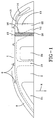
- Fig. 3 shows an alternative embodiment to the arrangement shown in Fig. 2.
- the arrangement according to Fig. 3 differs from the arrangement of Fig. 2 in that the airbag 2 and the holding strip 16 are secured on the vehicle body in the region of the roof beam 4 in a common fastening point 30. This simplifies the assembly of the airbag 2 and the holding strip 16 in the vehicle.
- the holding strip 16 and the airbag 2 can already be secured to each other in the region of the fastening point 30, before the airbag 2 and the holding strip 16 are then secured to the fastening point 30 in the vehicle.
- the holding strip 16 is connected to the airbag 2 in the region of its upper end 18 by tear seams 32.
- the tear seams 32 connect the holding strip 16 to the front section 34 of the airbag.
- the front section 34 of the airbag 2 constitutes the section which in the unfolding direction E during the unfolding of the airbag 2 lies at the front and forms the lower edge 22.
- the front end 34 of the airbag 2 therefore lies in the unfolded or inflated state of the airbag 2 in the proximity of the fastening point 28, as shown in Fig. 4.
- the arrangement of the tear seams 32 is not limited to the embodiment shown in Fig. 3, but it can also be foreseen for example with the embodiment shown in Fig. 2.
- the tear seams 32 enable a more simple and improved arrangement of the holding strip 16 with the folded airbag 2 in a vehicle.
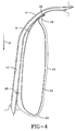
- Fig. 4 is a sectional view of the unfolded airbag 2 with the holding strip 16 according to the embodiment of Fig. 3.
- the unfolded state of the airbag 2 of the embodiment shown in Fig. 2 is essentially identical and differs from Fig. 4 only in terms of the separate fastening points 6 and 26.
- the inflated, i.e. blown-up airbag 2 extends from the roof beam 4 essentially parallel to the latter and the roof pillar 12.
- the airbag 2 in this case extends between the roof pillar 12 and the holding strip 16, whereby it essentially fills out the enclosed space between roof pillar 12 and holding strip 16.
- the airbag 2 and the holding strip 16 thus essentially form a non-interlocking contact fit, so that the airbag is secured to the holding strip 16.
- a non-interlocking and/or interlocking contact with the roof pillar 12 or a corresponding section of the inner side of the vehicle can be achieved to secure the airbag 2 to the inner side of the vehicle or the roof pillar 12.
- the front section 34 of the airbag 2 in this case also comes into contact with the holding strip 16 in the region of the lower end 20. This way the front section 34 of the airbag 2 is secured via the fastening point 28 by the holding strip 16 to the roof pillar 12.
- the front end 34 of the airbag 2 can thus no longer detach itself from the roof pillar 12 into the interior of the vehicle.
- the holding strip 16 can be designed as a closed loop, the two ends of which are connected with the car body to the fastening point 26 or 30 on the roof beam 4.
Landscapes
- Engineering & Computer Science (AREA)
- Mechanical Engineering (AREA)
- Air Bags (AREA)
Abstract
Description
Claims (10)
- Curtain airbag module comprising an airbag (2) which in its folded state can be arranged essentially along a region (4) of a vehicle roof, and at least one holding strip (16) which can be arranged in such a manner that it extends from the vehicle roof in an essentially transverse manner to the longitudinal extension of the folded airbag (2) and which, in the unfolding direction (E) of the airbag (2), can be secured to a inner side of the vehicle (12) at a distance from the vehicle roof, so that the airbag (2) can unfold between the holding strip (16) and the inner side of the vehicle (12).
- Curtain airbag module according to claim 1, in which the holding strip (16) can be secured with its first end (18) to the vehicle roof and with its second opposite end (20) to the inner side of the vehicle (12) at a distance from the vehicle roof.
- Curtain airbag module according to claim 1, in which the holding strip (16) is designed as a loop, the two ends of which can be secured to the vehicle roof, whereby one side of the loop can be secured at least to a particular point of the inner side of the vehicle (12), at a distance from the vehicle roof, so that the airbag (2) can be unfolded into the loop.
- Curtain airbag module according to one of the preceding claims, in which the holding strip (16) can be secured to the inner side of the vehicle (12) to a fastening point (28), at a distance from the vehicle roof which corresponds essentially to the extent of the unfolded airbag (2) in its unfolding direction (E).
- Curtain airbag module according to one of the preceding claims, in which the airbag (2) and the holding strip (16) comprise a common fastening point (30) for the fastening to the vehicle roof.
- Curtain airbag module according to one of the preceding claims, in which the holding strip (16) in the folded state can be arranged beneath an interior trim of the vehicle.
- Curtain airbag module according to claim 6, in which the interior trim comprises at least one set breaking point, enabling an ejection of the holding strip (16) during the unfolding of the airbag (2).
- Curtain airbag module according to one of the preceding claims, in which the holding strip (16) is connected to the folded airbag (2) by at least one tear seam (32), which tears open during the unfolding of the airbag (2).
- Curtain airbag module according to one of the preceding claims, in which the holding strip (16) can be arranged in the region of a roof pillar (12) of the vehicle.
- Curtain airbag module according to claim 9, in which the holding strip (16) can be arranged in such a manner that it extends essentially parallel to the roof pillar (12).
Applications Claiming Priority (2)
| Application Number | Priority Date | Filing Date | Title |
|---|---|---|---|
| DE10134802A DE10134802C2 (en) | 2001-07-17 | 2001-07-17 | Curtain airbag module |
| DE10134802 | 2001-07-17 |
Publications (2)
| Publication Number | Publication Date |
|---|---|
| EP1277625A2 true EP1277625A2 (en) | 2003-01-22 |
| EP1277625A3 EP1277625A3 (en) | 2003-02-05 |
Family
ID=7692133
Family Applications (1)
| Application Number | Title | Priority Date | Filing Date |
|---|---|---|---|
| EP02015604A Withdrawn EP1277625A3 (en) | 2001-07-17 | 2002-07-15 | Curtain-airbag-module |
Country Status (3)
| Country | Link |
|---|---|
| US (1) | US20030015862A1 (en) |
| EP (1) | EP1277625A3 (en) |
| DE (1) | DE10134802C2 (en) |
Families Citing this family (4)
| Publication number | Priority date | Publication date | Assignee | Title |
|---|---|---|---|---|
| US7850202B2 (en) * | 2007-03-02 | 2010-12-14 | Trw Vehicle Safety Systems Inc. | Inflatable curtain |
| KR101718690B1 (en) * | 2014-02-12 | 2017-04-04 | 아우토리브 디벨롭먼트 아베 | Side curtain airbag for vehicle |
| DE102019001260A1 (en) | 2019-02-21 | 2019-07-25 | Daimler Ag | Safety device for a vehicle |
| US11548469B2 (en) * | 2021-04-14 | 2023-01-10 | Autoliv Asp, Inc. | Inflatable curtain airbag |
Family Cites Families (6)
| Publication number | Priority date | Publication date | Assignee | Title |
|---|---|---|---|---|
| JP3039089B2 (en) * | 1991-11-22 | 2000-05-08 | タカタ株式会社 | Car occupant head protection device |
| US5588672A (en) * | 1995-10-20 | 1996-12-31 | Takata, Inc. | Side impact head restraint with inflatable deployment |
| DE29605896U1 (en) * | 1996-03-29 | 1996-07-25 | Trw Occupant Restraint Systems Gmbh, 73551 Alfdorf | Side impact protection device for vehicle occupants |
| DE29907912U1 (en) * | 1999-05-04 | 1999-09-16 | Trw Repa Gmbh | Side airbag restraint system |
| DE19926269B4 (en) * | 1999-06-10 | 2004-07-15 | Daimlerchrysler Ag | Protective device for the head and shoulder area of vehicle occupants |
| DE10042591A1 (en) * | 1999-09-03 | 2001-04-26 | Trw Repa Gmbh | Passenger protection system for vehicles has inflatable tube to move underneath roof and material web with two layers movable by inflating tube to extend perpendicular for side protection |
-
2001
- 2001-07-17 DE DE10134802A patent/DE10134802C2/en not_active Expired - Fee Related
-
2002
- 2002-05-17 US US10/146,941 patent/US20030015862A1/en not_active Abandoned
- 2002-07-15 EP EP02015604A patent/EP1277625A3/en not_active Withdrawn
Also Published As
| Publication number | Publication date |
|---|---|
| EP1277625A3 (en) | 2003-02-05 |
| US20030015862A1 (en) | 2003-01-23 |
| DE10134802C2 (en) | 2003-05-22 |
| DE10134802A1 (en) | 2003-02-13 |
Similar Documents
| Publication | Publication Date | Title |
|---|---|---|
| KR100200177B1 (en) | Gas back side impact protection device | |
| JP2860286B2 (en) | Gas bag protector for lateral impact | |
| US6517110B1 (en) | Dynamically deployed device shield | |
| CN101208223B (en) | Curtain airbag and vehicle | |
| JP2019031167A (en) | Curtain airbag device mounting structure and curtain airbag deployment method | |
| WO1998019893A1 (en) | Arrangement and construction of crew protective device for automobile | |
| JPH1178757A (en) | Head protection airbag device | |
| JP2004314706A (en) | Occupant restraint | |
| JP2004067086A (en) | Occupant protection device for automobile | |
| US8960716B2 (en) | Curtain airbag housing structure | |
| KR20140012284A (en) | Mounting apparatus for curtatin airbag | |
| JPH05262198A (en) | Lid of air bag device for front passenger's seat | |
| JP3353722B2 (en) | Head protection airbag bag | |
| JP4432699B2 (en) | Airbag device | |
| JP3560127B2 (en) | Head protection airbag device for front and rear seats | |
| EP1277625A2 (en) | Curtain-airbag-module | |
| EP1700754A1 (en) | Curtain airbag device | |
| KR100778559B1 (en) | Front pillar trim structure of curtain air bag | |
| JP2001163160A (en) | Air bag device | |
| KR20120051332A (en) | Curtain airbag apparatus | |
| JP7368210B2 (en) | Airbag and its folding method | |
| JP4259197B2 (en) | Arrangement structure of head airbag device | |
| JP3786852B2 (en) | Automotive airbag equipment | |
| JP4112412B2 (en) | Curtain airbag device | |
| JPH10157550A (en) | Side air bag device |
Legal Events
| Date | Code | Title | Description |
|---|---|---|---|
| PUAI | Public reference made under article 153(3) epc to a published international application that has entered the european phase |
Free format text: ORIGINAL CODE: 0009012 |
|
| PUAL | Search report despatched |
Free format text: ORIGINAL CODE: 0009013 |
|
| AK | Designated contracting states |
Kind code of ref document: A2 Designated state(s): AT BE BG CH CY CZ DE DK EE ES FI FR GB GR IE IT LI LU MC NL PT SE SK TR |
|
| AX | Request for extension of the european patent |
Free format text: AL;LT;LV;MK;RO;SI |
|
| AK | Designated contracting states |
Designated state(s): AT BE BG CH CY CZ DE DK EE ES FI FR GB GR IE IT LI LU MC NL PT SE SK TR |
|
| AX | Request for extension of the european patent |
Extension state: AL LT LV MK RO SI |
|
| 17P | Request for examination filed |
Effective date: 20030312 |
|
| 17Q | First examination report despatched |
Effective date: 20030527 |
|
| AKX | Designation fees paid |
Designated state(s): DE FR GB IT |
|
| STAA | Information on the status of an ep patent application or granted ep patent |
Free format text: STATUS: THE APPLICATION IS DEEMED TO BE WITHDRAWN |
|
| 18D | Application deemed to be withdrawn |
Effective date: 20031007 |