EP1277494A2 - Contoured housing for an implantable medical device - Google Patents
Contoured housing for an implantable medical device Download PDFInfo
- Publication number
- EP1277494A2 EP1277494A2 EP02016127A EP02016127A EP1277494A2 EP 1277494 A2 EP1277494 A2 EP 1277494A2 EP 02016127 A EP02016127 A EP 02016127A EP 02016127 A EP02016127 A EP 02016127A EP 1277494 A2 EP1277494 A2 EP 1277494A2
- Authority
- EP
- European Patent Office
- Prior art keywords
- major side
- side walls
- medical device
- implantable medical
- curvature
- Prior art date
- Legal status (The legal status is an assumption and is not a legal conclusion. Google has not performed a legal analysis and makes no representation as to the accuracy of the status listed.)
- Granted
Links
- 230000000747 cardiac effect Effects 0.000 claims description 5
- PXHVJJICTQNCMI-UHFFFAOYSA-N Nickel Chemical compound [Ni] PXHVJJICTQNCMI-UHFFFAOYSA-N 0.000 claims description 4
- 229910001209 Low-carbon steel Inorganic materials 0.000 claims description 2
- RTAQQCXQSZGOHL-UHFFFAOYSA-N Titanium Chemical compound [Ti] RTAQQCXQSZGOHL-UHFFFAOYSA-N 0.000 claims description 2
- 229910052782 aluminium Inorganic materials 0.000 claims description 2
- XAGFODPZIPBFFR-UHFFFAOYSA-N aluminium Chemical compound [Al] XAGFODPZIPBFFR-UHFFFAOYSA-N 0.000 claims description 2
- 239000003814 drug Substances 0.000 claims description 2
- 229940079593 drug Drugs 0.000 claims description 2
- 229910052759 nickel Inorganic materials 0.000 claims description 2
- 229910001220 stainless steel Inorganic materials 0.000 claims description 2
- 239000010935 stainless steel Substances 0.000 claims description 2
- 229910052715 tantalum Inorganic materials 0.000 claims description 2
- GUVRBAGPIYLISA-UHFFFAOYSA-N tantalum atom Chemical compound [Ta] GUVRBAGPIYLISA-UHFFFAOYSA-N 0.000 claims description 2
- 239000010936 titanium Substances 0.000 claims description 2
- 229910052719 titanium Inorganic materials 0.000 claims description 2
- 239000000463 material Substances 0.000 claims 1
- 230000007704 transition Effects 0.000 description 6
- 239000011521 glass Substances 0.000 description 4
- 238000009412 basement excavation Methods 0.000 description 3
- 239000000919 ceramic Substances 0.000 description 3
- 230000002093 peripheral effect Effects 0.000 description 3
- 238000002513 implantation Methods 0.000 description 2
- 229910052751 metal Inorganic materials 0.000 description 2
- 239000002184 metal Substances 0.000 description 2
- 238000003466 welding Methods 0.000 description 2
- 210000003484 anatomy Anatomy 0.000 description 1
- 230000009286 beneficial effect Effects 0.000 description 1
- 239000003990 capacitor Substances 0.000 description 1
- 239000004020 conductor Substances 0.000 description 1
- 239000003792 electrolyte Substances 0.000 description 1
- 238000009413 insulation Methods 0.000 description 1
- 238000012986 modification Methods 0.000 description 1
- 230000004048 modification Effects 0.000 description 1
- 210000003625 skull Anatomy 0.000 description 1
Images



Classifications
-
- A—HUMAN NECESSITIES
- A61—MEDICAL OR VETERINARY SCIENCE; HYGIENE
- A61N—ELECTROTHERAPY; MAGNETOTHERAPY; RADIATION THERAPY; ULTRASOUND THERAPY
- A61N1/00—Electrotherapy; Circuits therefor
- A61N1/18—Applying electric currents by contact electrodes
- A61N1/32—Applying electric currents by contact electrodes alternating or intermittent currents
- A61N1/36—Applying electric currents by contact electrodes alternating or intermittent currents for stimulation
- A61N1/372—Arrangements in connection with the implantation of stimulators
- A61N1/375—Constructional arrangements, e.g. casings
-
- A—HUMAN NECESSITIES
- A61—MEDICAL OR VETERINARY SCIENCE; HYGIENE
- A61N—ELECTROTHERAPY; MAGNETOTHERAPY; RADIATION THERAPY; ULTRASOUND THERAPY
- A61N1/00—Electrotherapy; Circuits therefor
- A61N1/18—Applying electric currents by contact electrodes
- A61N1/32—Applying electric currents by contact electrodes alternating or intermittent currents
- A61N1/36—Applying electric currents by contact electrodes alternating or intermittent currents for stimulation
- A61N1/372—Arrangements in connection with the implantation of stimulators
- A61N1/375—Constructional arrangements, e.g. casings
- A61N1/37512—Pacemakers
-
- H—ELECTRICITY
- H01—ELECTRIC ELEMENTS
- H01M—PROCESSES OR MEANS, e.g. BATTERIES, FOR THE DIRECT CONVERSION OF CHEMICAL ENERGY INTO ELECTRICAL ENERGY
- H01M50/00—Constructional details or processes of manufacture of the non-active parts of electrochemical cells other than fuel cells, e.g. hybrid cells
- H01M50/10—Primary casings; Jackets or wrappings
- H01M50/102—Primary casings; Jackets or wrappings characterised by their shape or physical structure
- H01M50/103—Primary casings; Jackets or wrappings characterised by their shape or physical structure prismatic or rectangular
-
- H—ELECTRICITY
- H01—ELECTRIC ELEMENTS
- H01M—PROCESSES OR MEANS, e.g. BATTERIES, FOR THE DIRECT CONVERSION OF CHEMICAL ENERGY INTO ELECTRICAL ENERGY
- H01M50/00—Constructional details or processes of manufacture of the non-active parts of electrochemical cells other than fuel cells, e.g. hybrid cells
- H01M50/20—Mountings; Secondary casings or frames; Racks, modules or packs; Suspension devices; Shock absorbers; Transport or carrying devices; Holders
- H01M50/202—Casings or frames around the primary casing of a single cell or a single battery
-
- H—ELECTRICITY
- H01—ELECTRIC ELEMENTS
- H01M—PROCESSES OR MEANS, e.g. BATTERIES, FOR THE DIRECT CONVERSION OF CHEMICAL ENERGY INTO ELECTRICAL ENERGY
- H01M50/00—Constructional details or processes of manufacture of the non-active parts of electrochemical cells other than fuel cells, e.g. hybrid cells
- H01M50/20—Mountings; Secondary casings or frames; Racks, modules or packs; Suspension devices; Shock absorbers; Transport or carrying devices; Holders
- H01M50/218—Mountings; Secondary casings or frames; Racks, modules or packs; Suspension devices; Shock absorbers; Transport or carrying devices; Holders characterised by the material
- H01M50/22—Mountings; Secondary casings or frames; Racks, modules or packs; Suspension devices; Shock absorbers; Transport or carrying devices; Holders characterised by the material of the casings or racks
- H01M50/222—Inorganic material
- H01M50/224—Metals
-
- H—ELECTRICITY
- H01—ELECTRIC ELEMENTS
- H01M—PROCESSES OR MEANS, e.g. BATTERIES, FOR THE DIRECT CONVERSION OF CHEMICAL ENERGY INTO ELECTRICAL ENERGY
- H01M50/00—Constructional details or processes of manufacture of the non-active parts of electrochemical cells other than fuel cells, e.g. hybrid cells
- H01M50/20—Mountings; Secondary casings or frames; Racks, modules or packs; Suspension devices; Shock absorbers; Transport or carrying devices; Holders
- H01M50/247—Mountings; Secondary casings or frames; Racks, modules or packs; Suspension devices; Shock absorbers; Transport or carrying devices; Holders specially adapted for portable devices, e.g. mobile phones, computers, hand tools or pacemakers
-
- H—ELECTRICITY
- H01—ELECTRIC ELEMENTS
- H01M—PROCESSES OR MEANS, e.g. BATTERIES, FOR THE DIRECT CONVERSION OF CHEMICAL ENERGY INTO ELECTRICAL ENERGY
- H01M50/00—Constructional details or processes of manufacture of the non-active parts of electrochemical cells other than fuel cells, e.g. hybrid cells
- H01M50/20—Mountings; Secondary casings or frames; Racks, modules or packs; Suspension devices; Shock absorbers; Transport or carrying devices; Holders
- H01M50/271—Lids or covers for the racks or secondary casings
-
- H—ELECTRICITY
- H01—ELECTRIC ELEMENTS
- H01M—PROCESSES OR MEANS, e.g. BATTERIES, FOR THE DIRECT CONVERSION OF CHEMICAL ENERGY INTO ELECTRICAL ENERGY
- H01M50/00—Constructional details or processes of manufacture of the non-active parts of electrochemical cells other than fuel cells, e.g. hybrid cells
- H01M50/50—Current conducting connections for cells or batteries
- H01M50/543—Terminals
- H01M50/545—Terminals formed by the casing of the cells
-
- H—ELECTRICITY
- H01—ELECTRIC ELEMENTS
- H01M—PROCESSES OR MEANS, e.g. BATTERIES, FOR THE DIRECT CONVERSION OF CHEMICAL ENERGY INTO ELECTRICAL ENERGY
- H01M50/00—Constructional details or processes of manufacture of the non-active parts of electrochemical cells other than fuel cells, e.g. hybrid cells
- H01M50/50—Current conducting connections for cells or batteries
- H01M50/572—Means for preventing undesired use or discharge
- H01M50/584—Means for preventing undesired use or discharge for preventing incorrect connections inside or outside the batteries
- H01M50/59—Means for preventing undesired use or discharge for preventing incorrect connections inside or outside the batteries characterised by the protection means
- H01M50/591—Covers
-
- A—HUMAN NECESSITIES
- A61—MEDICAL OR VETERINARY SCIENCE; HYGIENE
- A61N—ELECTROTHERAPY; MAGNETOTHERAPY; RADIATION THERAPY; ULTRASOUND THERAPY
- A61N1/00—Electrotherapy; Circuits therefor
- A61N1/18—Applying electric currents by contact electrodes
- A61N1/32—Applying electric currents by contact electrodes alternating or intermittent currents
- A61N1/36—Applying electric currents by contact electrodes alternating or intermittent currents for stimulation
- A61N1/372—Arrangements in connection with the implantation of stimulators
- A61N1/375—Constructional arrangements, e.g. casings
- A61N1/3758—Packaging of the components within the casing
-
- H—ELECTRICITY
- H01—ELECTRIC ELEMENTS
- H01M—PROCESSES OR MEANS, e.g. BATTERIES, FOR THE DIRECT CONVERSION OF CHEMICAL ENERGY INTO ELECTRICAL ENERGY
- H01M10/00—Secondary cells; Manufacture thereof
- H01M10/05—Accumulators with non-aqueous electrolyte
- H01M10/052—Li-accumulators
- H01M10/0525—Rocking-chair batteries, i.e. batteries with lithium insertion or intercalation in both electrodes; Lithium-ion batteries
-
- H—ELECTRICITY
- H01—ELECTRIC ELEMENTS
- H01M—PROCESSES OR MEANS, e.g. BATTERIES, FOR THE DIRECT CONVERSION OF CHEMICAL ENERGY INTO ELECTRICAL ENERGY
- H01M4/00—Electrodes
- H01M4/02—Electrodes composed of, or comprising, active material
- H01M4/36—Selection of substances as active materials, active masses, active liquids
- H01M4/48—Selection of substances as active materials, active masses, active liquids of inorganic oxides or hydroxides
-
- H—ELECTRICITY
- H01—ELECTRIC ELEMENTS
- H01M—PROCESSES OR MEANS, e.g. BATTERIES, FOR THE DIRECT CONVERSION OF CHEMICAL ENERGY INTO ELECTRICAL ENERGY
- H01M4/00—Electrodes
- H01M4/02—Electrodes composed of, or comprising, active material
- H01M4/36—Selection of substances as active materials, active masses, active liquids
- H01M4/48—Selection of substances as active materials, active masses, active liquids of inorganic oxides or hydroxides
- H01M4/485—Selection of substances as active materials, active masses, active liquids of inorganic oxides or hydroxides of mixed oxides or hydroxides for inserting or intercalating light metals, e.g. LiTi2O4 or LiTi2OxFy
-
- H—ELECTRICITY
- H01—ELECTRIC ELEMENTS
- H01M—PROCESSES OR MEANS, e.g. BATTERIES, FOR THE DIRECT CONVERSION OF CHEMICAL ENERGY INTO ELECTRICAL ENERGY
- H01M4/00—Electrodes
- H01M4/02—Electrodes composed of, or comprising, active material
- H01M4/36—Selection of substances as active materials, active masses, active liquids
- H01M4/58—Selection of substances as active materials, active masses, active liquids of inorganic compounds other than oxides or hydroxides, e.g. sulfides, selenides, tellurides, halogenides or LiCoFy; of polyanionic structures, e.g. phosphates, silicates or borates
- H01M4/583—Carbonaceous material, e.g. graphite-intercalation compounds or CFx
-
- H—ELECTRICITY
- H01—ELECTRIC ELEMENTS
- H01M—PROCESSES OR MEANS, e.g. BATTERIES, FOR THE DIRECT CONVERSION OF CHEMICAL ENERGY INTO ELECTRICAL ENERGY
- H01M50/00—Constructional details or processes of manufacture of the non-active parts of electrochemical cells other than fuel cells, e.g. hybrid cells
- H01M50/10—Primary casings; Jackets or wrappings
- H01M50/116—Primary casings; Jackets or wrappings characterised by the material
- H01M50/117—Inorganic material
- H01M50/119—Metals
-
- H—ELECTRICITY
- H01—ELECTRIC ELEMENTS
- H01M—PROCESSES OR MEANS, e.g. BATTERIES, FOR THE DIRECT CONVERSION OF CHEMICAL ENERGY INTO ELECTRICAL ENERGY
- H01M50/00—Constructional details or processes of manufacture of the non-active parts of electrochemical cells other than fuel cells, e.g. hybrid cells
- H01M50/10—Primary casings; Jackets or wrappings
- H01M50/147—Lids or covers
-
- H—ELECTRICITY
- H01—ELECTRIC ELEMENTS
- H01M—PROCESSES OR MEANS, e.g. BATTERIES, FOR THE DIRECT CONVERSION OF CHEMICAL ENERGY INTO ELECTRICAL ENERGY
- H01M50/00—Constructional details or processes of manufacture of the non-active parts of electrochemical cells other than fuel cells, e.g. hybrid cells
- H01M50/20—Mountings; Secondary casings or frames; Racks, modules or packs; Suspension devices; Shock absorbers; Transport or carrying devices; Holders
- H01M50/298—Mountings; Secondary casings or frames; Racks, modules or packs; Suspension devices; Shock absorbers; Transport or carrying devices; Holders characterised by the wiring of battery packs
-
- H—ELECTRICITY
- H01—ELECTRIC ELEMENTS
- H01M—PROCESSES OR MEANS, e.g. BATTERIES, FOR THE DIRECT CONVERSION OF CHEMICAL ENERGY INTO ELECTRICAL ENERGY
- H01M50/00—Constructional details or processes of manufacture of the non-active parts of electrochemical cells other than fuel cells, e.g. hybrid cells
- H01M50/60—Arrangements or processes for filling or topping-up with liquids; Arrangements or processes for draining liquids from casings
- H01M50/609—Arrangements or processes for filling with liquid, e.g. electrolytes
- H01M50/627—Filling ports
-
- H—ELECTRICITY
- H01—ELECTRIC ELEMENTS
- H01M—PROCESSES OR MEANS, e.g. BATTERIES, FOR THE DIRECT CONVERSION OF CHEMICAL ENERGY INTO ELECTRICAL ENERGY
- H01M6/00—Primary cells; Manufacture thereof
- H01M6/04—Cells with aqueous electrolyte
- H01M6/06—Dry cells, i.e. cells wherein the electrolyte is rendered non-fluid
- H01M6/10—Dry cells, i.e. cells wherein the electrolyte is rendered non-fluid with wound or folded electrodes
-
- H—ELECTRICITY
- H01—ELECTRIC ELEMENTS
- H01M—PROCESSES OR MEANS, e.g. BATTERIES, FOR THE DIRECT CONVERSION OF CHEMICAL ENERGY INTO ELECTRICAL ENERGY
- H01M6/00—Primary cells; Manufacture thereof
- H01M6/14—Cells with non-aqueous electrolyte
- H01M6/16—Cells with non-aqueous electrolyte with organic electrolyte
-
- Y—GENERAL TAGGING OF NEW TECHNOLOGICAL DEVELOPMENTS; GENERAL TAGGING OF CROSS-SECTIONAL TECHNOLOGIES SPANNING OVER SEVERAL SECTIONS OF THE IPC; TECHNICAL SUBJECTS COVERED BY FORMER USPC CROSS-REFERENCE ART COLLECTIONS [XRACs] AND DIGESTS
- Y02—TECHNOLOGIES OR APPLICATIONS FOR MITIGATION OR ADAPTATION AGAINST CLIMATE CHANGE
- Y02E—REDUCTION OF GREENHOUSE GAS [GHG] EMISSIONS, RELATED TO ENERGY GENERATION, TRANSMISSION OR DISTRIBUTION
- Y02E60/00—Enabling technologies; Technologies with a potential or indirect contribution to GHG emissions mitigation
- Y02E60/10—Energy storage using batteries
Definitions
- the present invention relates to implantable medical devices and, more particularly, to housings for implantable medical devices.
- the housings have contoured surfaces to more closely conform to body contours. This facilitates implantation in areas of a body that were heretofore not possible because of geometrical limitations.
- Implantable medical devices include hearing-assist devices, artificial hearts, neurostimulators, drug pumps, cardiac pacemakers, cardiac defibrillators and heart-assist devices.
- these devices include a housing with planar side walls, such as in a prismatic design.
- the shape of the housing limits the areas in a body, human or otherwise, in which the device can be implanted. If an area of the body, such as the skull, must be excavated, a conventional prismatic housing requires that the cavity be shaped to fit the planar prismatic design. This may necessitate more excavation than is required if the housing is contoured to fit the patient's anatomy.
- the planar design of current prismatic housings makes it more difficult for implantable devices to be placed in other locations in the body such as the arms and legs.
- the cell 12 is comprised of a casing 14 having spaced apart and opposed major front and back side walls 16 and 18.
- the walls 16, 18 each have a generally semicircular shape with a planar upper edge.
- the side walls 16, 18 extend to and meet with a semicircular intermediate end wall 20 that curves to meet them along their entire radial perimeter.
- the side walls 16, 18 and end wall 20 form the casing as a unitary, deep drawn member.
- Both of the major front and back side walls 16, 18 have a curved shape of a continuous radius deflecting in a similar direction and extending from the end wall 20.
- the side walls and end wall of the deep drawn casing 14 form an opening closed by a lid 22.
- the lid also includes an electrolyte fill opening 24 closed by ball 26 and a terminal pin opening supporting a ring of insulation glass 28 surrounding a terminal pin 30 for one of the anode and the cathode electrodes of the cell.
- the casing 14 serves as the terminal for the other electrode.
- the electrochemical cell 12 serves as the power supply for the control circuitry 32 of the implantable device 10.
- Lead 34 connected to the casing 14, and terminal pin 30 provides electrical power from the cell to the control circuitry.
- the implantable device 10 includes a housing 36 having spaced apart and opposed major front and back side walls 38 and 40.
- the walls 38, 40 each have a generally semicircular shape with a planar upper edge.
- the walls 38, 40 extend to and meet with a semicircular intermediate end wall 42 that curves to meet them along their entire radial perimeter.
- the side walls 38, 40 and end wall 42 form the housing 36 as a unitary, deep drawn member.
- Both the front and back major side walls 38, 40 have a curved shape of a continuous radius deflecting in a similar direction and extending from the end wall 42.
- the side walls and end walls of the deep drawn housing 60 form an opening 72 closed by a generally planar lid 74.
- Lid 74 has a peripheral shape matching that of the opening 72 and formed of a concave edge 76 opposite a convex edge 78, both of which extend to and meet with curved right and left edges 80 and 82. That way, when the lid 74 is secured to the upper edges of the housing side walls and end walls, the opening 72 is closed in a hermetic manner.
- the lid 74 includes feedthrough wires 84 and 86 for connection to the body being assisted.
- the feedthrough wires 84, 86 are insulated from the lid by respective glass or ceramic seals 88, 90.
- the side walls and end walls of the deep drawn housing 100 form an opening 112 closed by a generally planar lid 114.
- Lid 114 has a peripheral shape matching that of the opening 112 and formed of a concave edge 116 opposite a convex edge 118, both of which extend to and meet with straight right and left edges 120 and 122. That way, when the lid 114 is secured to the upper edges of the housing side walls and end walls, the opening 112 is closed.
- Fig. 4 illustrates another embodiment of a contoured deep drawn housing 140 having spaced apart and opposed front and back side walls 142 and 144 extending to and meeting with curved right and left end walls 146 and 148.
- the side walls 142, 144 and end walls 146, 148 connect to a bottom wall (not shown) forming the housing as a unitary member.
- Both of the major front and back side walls 142, 144 have a curved shape of a continuous radius deflecting in a similar direction and extending from the end walls 146, 148.
- the curvature of front wall 142 is less than that of back wall 144. This means that the radius of the front wall 142 is greater than the radius of the back wall 144.
- the side walls and end walls of the deep drawn housing 140 form an opening 150 closed by a lid 152.
- Lid 152 has a peripheral shape matching that of the opening 150.
- the lid also includes feedthrough wires 154, 156 for connection to the body being assisted.
- the feedthrough wires 154, 156 are insulated from the lid 152 by respective glass or ceramic seals 158, 160.
- the second clam shell 174 has a surrounding wall comprised of spaced apart side walls 188 and 290 extending to and meeting with spaced apart end walls 192 and 194.
- the side walls 188 and 190 and end walls 192 and 194 meet at rounded corners and extend to a curved front wall 196 of a generally concave shape.
- Opposite the front wall is a continuous edge 198 of the side walls 188, 190 and end walls 192, 194.
- the clam shells 172 and 174 are sized such that one of them has its side walls and end walls of a somewhat shorter length than those of the other. That way, after the components of the implantable device, including the power source and control circuitry, are nested in the one clam shell having the shorter side walls and end walls, the other clam shell is mated thereto. In this position, the shorter side walls and end walls are received in a closely spaced relationship partially covered by the somewhat longer side walls and end walls of the other clam shell. The one continuous edge 186, 198 of the larger clam shell is then secured to the side walls and end walls of the other clam shell, such as by welding.
- the arrangement of the respective curved portions 226, 232 and 236 can be rearranged in any sequence or manner. Also, there can be only two different curved portions in a side wall or more than three. The exact number and their arrangement is only limited by the parameters of the particular application in which the implantable device cell will be used.
- Fig. 8 shows another embodiment of a housing 250 comprising spaced apart and opposed major first and second curved side walls 252 and 254 according to the present invention.
- the first major side wall 252 is comprised of a first curved portion 256 defined by radius R5 moving along a path from tangent point 258 to tangent point 260 where the side wall transitions to a first planar or straight portion 262.
- the first planar portion 262 then transitions to a second curved portion 264 defined by radius R6 moving along a path from tangent point 266 to tangent point 268.
- the side wall 252 transitions to a second planar portion 270 which, in turn, transitions to a third curved portion 272 defined by radius R7 moving along a path from tangent point 274 to tangent point 276.
Landscapes
- Chemical & Material Sciences (AREA)
- General Chemical & Material Sciences (AREA)
- Electrochemistry (AREA)
- Chemical Kinetics & Catalysis (AREA)
- Health & Medical Sciences (AREA)
- Life Sciences & Earth Sciences (AREA)
- Engineering & Computer Science (AREA)
- Animal Behavior & Ethology (AREA)
- Biomedical Technology (AREA)
- Veterinary Medicine (AREA)
- Biophysics (AREA)
- Public Health (AREA)
- General Health & Medical Sciences (AREA)
- Radiology & Medical Imaging (AREA)
- Nuclear Medicine, Radiotherapy & Molecular Imaging (AREA)
- Inorganic Chemistry (AREA)
- Heart & Thoracic Surgery (AREA)
- Computer Hardware Design (AREA)
- Prostheses (AREA)
- Electrotherapy Devices (AREA)
- Battery Electrode And Active Subsutance (AREA)
- Sealing Battery Cases Or Jackets (AREA)
- Primary Cells (AREA)
- Secondary Cells (AREA)
- Infusion, Injection, And Reservoir Apparatuses (AREA)
- External Artificial Organs (AREA)
Abstract
Description
- This application claims priority based on provisional application Serial No. 60/306,647, filed July 19, 2001.
- The present invention relates to implantable medical devices and, more particularly, to housings for implantable medical devices. The housings have contoured surfaces to more closely conform to body contours. This facilitates implantation in areas of a body that were heretofore not possible because of geometrical limitations.
- Implantable medical devices include hearing-assist devices, artificial hearts, neurostimulators, drug pumps, cardiac pacemakers, cardiac defibrillators and heart-assist devices. Conventionally, these devices include a housing with planar side walls, such as in a prismatic design. However, the shape of the housing limits the areas in a body, human or otherwise, in which the device can be implanted. If an area of the body, such as the skull, must be excavated, a conventional prismatic housing requires that the cavity be shaped to fit the planar prismatic design. This may necessitate more excavation than is required if the housing is contoured to fit the patient's anatomy. Furthermore, the planar design of current prismatic housings makes it more difficult for implantable devices to be placed in other locations in the body such as the arms and legs.
- Accordingly, there is a need for a housing for an implantable medical device that is shaped or contoured to more closely fit the curved shape of a body. This facilitates implanting assist devices in areas where it is difficult, if not impossible, to place conventionally shaped devices. Furthermore, not only does a contoured shaped housing aid in the placement of assist devices into the body where they could not previously be placed, but it also helps in placing them in areas of the body where they are frequently used, but without undo excavation.
- These and other advantages of the present invention will become increasingly more apparent to those of ordinary skill in the art by reference to the following description together with the appended drawings.
-
- Fig. 1 is an elevational view, partly broken away,
of an implantable
medical device 10 comprised of acontoured housing 36 with apower source 12 of a contouredcasing 14 housed therein. - Fig. 2A is an exploded view of one embodiment of a
contoured deep drawn
cell housing 30 according to the present invention. - Fig. 2B is a side elevational view of the
housing 30 shown in Fig. 2A. - Fig. 3A is an exploded view of another embodiment
of a contoured deep drawn
cell housing 70 according to the present invention. - Fig. 3B is a side elevational view of the
housing 70 shown in Fig. 3A. - Fig. 4 is a perspective view of another embodiment
of a
contoured housing 270 according to the present invention having afront side wall 272 of a greater radial curvature than aback side wall 274. - Fig. 5 is a perspective view of contoured clam
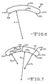
shell housing portions housing 110. - Fig. 6 is a schematic cross-sectional view of a housing having opposed major curved side walls of a radius R1.
- Fig. 7 is a schematic cross-sectional view of a housing having opposed major curved side walls of varying radii R2 to R4.
- Fig. 8 is a schematic cross-sectional view of a housing having opposed major curved side walls of substantially equal radii R5 to R6 with intermediate planar sections.
-
- Fig. 1 shows a representative
implantable device 10 powered by an implantableelectrochemical cell 12. Both thedevice 10 and thecell 12 are comprised of housings or casings having contoured side walls according to the present invention The housings and casings of this invention are preferably of conductive materials selected from nickel, aluminum, stainless steel, mild steel, tantalum and titanium. - The
cell 12 is comprised of acasing 14 having spaced apart and opposed major front andback side walls walls side walls intermediate end wall 20 that curves to meet them along their entire radial perimeter. Theside walls end wall 20 form the casing as a unitary, deep drawn member. Both of the major front andback side walls end wall 20. - The side walls and end wall of the deep drawn
casing 14 form an opening closed by alid 22. The lid also includes an electrolyte fill opening 24 closed byball 26 and a terminal pin opening supporting a ring ofinsulation glass 28 surrounding aterminal pin 30 for one of the anode and the cathode electrodes of the cell. Thecasing 14 serves as the terminal for the other electrode. For a more detailed description of this type of cell, reference is made to U.S. Patent No. 5,905,001 to Elliott et al., which is assigned to the assignee to the present invention and incorporated herein by reference. - The
electrochemical cell 12 serves as the power supply for thecontrol circuitry 32 of theimplantable device 10.Lead 34, connected to thecasing 14, andterminal pin 30 provides electrical power from the cell to the control circuitry. There may also be a capacitor (not shown) inside the casing for a medical device such as a cardiac defibrillator. - The
implantable device 10 includes ahousing 36 having spaced apart and opposed major front andback side walls walls walls intermediate end wall 42 that curves to meet them along their entire radial perimeter. Theside walls end wall 42 form thehousing 36 as a unitary, deep drawn member. Both the front and backmajor side walls end wall 42. - The side walls and end wall of the deep drawn
housing 36 form an opening closed by alid 44. Thelid 44 comprises twoopenings respective feedthrough wires housing 36 connected to thecontrol circuitry 32 for themedical device 10 to proximal ends for connection to leads (not shown). The leads connect the medical device to the body being assisted. Thefeedthrough wires lid 44 by respective ceramic-to-metal seals or glass-to-metal seals - In that manner, the
device 10 is implantable into areas of the body which may not have been considered before with devices having more prismatic shapes with rectangular cross-sections. Also, theimplantable device 10 more closely conforms to the contours of a body so that when it is used to assist a person, there may be less excavation required than is currently needed with conventionally shaped devices. - Turning to Figs. 2A, 2B, 3A, 3B and 4, these drawings show other representative shapes for deep drawn
medical device housings - The
housing 60 illustrated in Figs. 2A and 2B includes spaced apart and opposed major front andback side walls left end walls side walls walls planar bottom wall 70 forming the housing as a unitary, deep drawn member. Both of the major front and backside walls left end walls side walls front wall 62 with a greater curvature than theback wall 64. This would optimize internal volume while maintaining housing curvature for implantation purposes, and the like. - The side walls and end walls of the deep drawn
housing 60 form anopening 72 closed by a generallyplanar lid 74.Lid 74 has a peripheral shape matching that of theopening 72 and formed of aconcave edge 76 opposite aconvex edge 78, both of which extend to and meet with curved right and leftedges lid 74 is secured to the upper edges of the housing side walls and end walls, theopening 72 is closed in a hermetic manner. - The
lid 74 includesfeedthrough wires feedthrough wires ceramic seals - Figs. 3A and 3B illustrate another embodiment of a contoured
deep drawing housing 100 including spaced apart and opposed major front and backside walls left end walls side walls walls curved bottom wall 110 forming the housing as a unitary, deep drawn member. Both of the major front and backside walls left end walls side walls housing 60, that is not necessary. - The side walls and end walls of the deep drawn
housing 100 form anopening 112 closed by a generallyplanar lid 114.Lid 114 has a peripheral shape matching that of theopening 112 and formed of a concave edge 116 opposite aconvex edge 118, both of which extend to and meet with straight right and leftedges 120 and 122. That way, when thelid 114 is secured to the upper edges of the housing side walls and end walls, theopening 112 is closed. - As with the
housing 60 of Figs. 2A and 2B, thelid 114 includesfeedthrough wires feedthrough wires lid 114 by respective glass orceramic seals - Fig. 4 illustrates another embodiment of a contoured deep drawn
housing 140 having spaced apart and opposed front and backside walls left end walls side walls walls side walls end walls front wall 142 is less than that ofback wall 144. This means that the radius of thefront wall 142 is greater than the radius of theback wall 144. - The side walls and end walls of the deep drawn
housing 140 form anopening 150 closed by alid 152.Lid 152 has a peripheral shape matching that of theopening 150. When the lid is secured to the upper edges of the housing, theopening 150 is closed in a hermetic manner. The lid also includesfeedthrough wires feedthrough wires lid 152 by respective glass orceramic seals - Fig. 5 illustrates another embodiment of a
contoured housing 170 according to the present invention. The housing has first and secondclam shell portions first clam shell 172 has a surrounding wall comprised of spaced apartside walls walls side walls end walls front wall 184 of a generally concave shape. Opposite thefront wall 184 is acontinuous edge 186 of theside walls walls - The
second clam shell 174 has a surrounding wall comprised of spaced apartside walls 188 and 290 extending to and meeting with spaced apart endwalls side walls walls front wall 196 of a generally concave shape. Opposite the front wall is acontinuous edge 198 of theside walls walls - The
clam shells continuous edge housing 170 having the majorconcave walls - It is also within the scope of the present invention that the clam shells are butted together before they are sealed. This means that instead of the side walls and end walls of one of the clam shells being shorter than those of the other, they are of equal lengths. The butted edges are sealed together such as by welding.
- Turning to Figs. 6 to 8, these drawings show further representative schematic cross-sectional views of housings haying contoured or curved opposed major side walls according to the present invention. In Fig. 6, the
housing 200 comprises spaced apart and opposed major first andsecond side walls Side wall 202 is of a curvature defined by the radius R1 moving along a path fromtangent point 206 totangent point 208. The radius R1 is not shown for thesecond side wall 204, however, it is the same as that of thefirst side wall 202. Theside walls curved end walls housing 200 is then hermetically closed by a lid (not shown). - Fig. 7 shows another embodiment of a
housing 220 comprising spaced apart and opposed major first and secondcurved side walls major side wall 222 is comprised of a firstcurved portion 226 defined by radius R2 moving along a path fromtangent point 228 totangent point 230 where the side wall transitions to a secondcurved portion 232 defined by radius R2 moving along a path fromtangent point 230 totangent point 234. Attangent point 234, the secondcurved portion 232 transitions to a thirdcurved portion 236 defined by radius R3 moving along a path fromtangent point 234 to tangent point 238. - As the drawing shows, the length of the radius R2 is less than that of both R3 and R4 while the length of radius R4 is less than that of R3. The second
major side wall 224 is similar in its contoured or curved shape. Theside walls curved end walls housing 220 is then heremetically closed by a lid (not shown). - It is within the scope of the present invention that the arrangement of the respective
curved portions - Fig. 8 shows another embodiment of a
housing 250 comprising spaced apart and opposed major first and secondcurved side walls major side wall 252 is comprised of a firstcurved portion 256 defined by radius R5 moving along a path fromtangent point 258 totangent point 260 where the side wall transitions to a first planar orstraight portion 262. The firstplanar portion 262 then transitions to a secondcurved portion 264 defined by radius R6 moving along a path fromtangent point 266 totangent point 268. Attangent point 268, theside wall 252 transitions to a secondplanar portion 270 which, in turn, transitions to a thirdcurved portion 272 defined by radius R7 moving along a path fromtangent point 274 totangent point 276. - As the drawing shows, the lengths of radii R5, R6 and R7 are substantially equal. However, as described above with respect to Fig. 7, that is not necessary. The lengths of
planar portions - Again, the second
major side wall 254 is similar in shape to thefirst side wall 252. Theside walls curved end walls housing 250 is then hermetically closed by a lid (not shown). - It is appreciated that various modifications to the present inventive concepts described herein may be apparent to those of ordinary skill in the art without departing from the spirit and scope of the present invention as defined by the herein appended claims.
Claims (15)
- An implantable medical device (10), which comprises:a) an electrical energy power source (12);b) a control circuitry (32); andc) a housing (36) for the power source (12) and the control circuitry (32), wherein the housing (36) comprises spaced apart first and second major side walls (38, 40) extending to and meeting with opposed third and fourth end walls and a bottom wall, and wherein the first and second major side walls (38, 40) are curved where they connect to the third end wall and where they connect to the fourth end wall.
- The implantable medical device (10) of claim 1, wherein the first and second major side walls (38, 40) are continuously curved from their connection to the third end wall to their connection to the opposed fourth end wall, preferably wherein the first major side wall (38) is of a greater curvature than the second major side wall (40).
- The implantable medical device (10) of claim 1 or claim 2, wherein at least one of the first and second major side walls (38, 40) is of at least a first and a second different curvatures, the first curvature transitioning into the second curvature, or wherein at least one of the first and second major side walls (38, 40) is of at least a first and a second different curvatures with a generally planar surface disposed between the first curvature and the second curvature.
- The implantable medical device (10) of any of claims 1 to 3, wherein the third and fourth end walls are curved, or wherein the third and fourth end walls are generally planar.
- The implantable medical device (10) of any of claims 1 to 4, wherein the housing (36) includes a lid (44) opposite the bottom wall, preferably wherein the lid (44) supports at least one feedthrough pin (50, 52).
- The implantable medical device (10) of any of claims 1 to 5, selected from the group consisting of a hearing-assist device, a neurostimulator, a cardiac pacemaker, a cardiac defibrillator, a heart-assist device and a drug pump.
- The implantable medical device (10) of any of claims 1 to 6, wherein the housing (36) is of a material selected from the group consisting of nickel, aluminum, stainless steel, mild steel, tantalum and titanium.
- An implantable medical device (10), which comprises:a) an electrical energy power source (12);b) a control circuitry (32); andc) a housing (60) for the power source (12) and the control circuitry (32), wherein the housing (60) comprises spaced apart first and second major side walls (62, 64) extending to and meeting with an intermediate wall having a generally radius curved shape and wherein the first and second major side walls (62, 64) are curved where each of them meets the intermediate wall.
- The implantable medical device (10) of claim 8, wherein the first and second major side walls (62, 64) are of a continuous curvature.
- The implantable medical device (10) of claim 8 or claim 9, wherein at least one of the first and second major side walls (62, 64) is of at least a first and a second different curvatures, the first curvature transitioning with the second curvature, or wherein at least one of the first and second major side walls (62, 64) is of at least a first and a second different curvatures with a generally planar surface disposed between the first curvature and the second curvature.
- The implantable medical device (10) of any of claims 8 to 10, wherein the first major side wall (62) is of a greater curvature than the second major side wall (64).
- The implantable medical device (10) of any of claims 8 to 11, wherein the housing (60) includes a lid (74) connected to the first and second major side walls (62, 64) and the intermediate wall, preferably wherein the lid (74) supports at least one feedthrough pin (84, 86).
- An implantable medical device (10), which comprises:a) an electrical energy power source (12);b) a control circuitry (32); andc) a housing (170) for the power source (12) and the control circuitry (32), wherein the housing (170) comprises a first portion (172) having a first major side wall extending to and meeting with a first surrounding side wall and a second portion (174) having a second major side wall extending to and meeting with a second surrounding side wall and wherein the first and second portions (172, 174) are mated to each other with the first surrounding side wall contacting the second surrounding side wall.
- The implantable medical device (10) of claim 13, wherein the first and second major side walls are continuously curved, preferably wherein the first major side wall is of a greater curvature than the second major side wall.
- The implantable medical device (10) of claim 13 or claim 14, wherein at least one of the first and second major side walls is of at least a first and second different curvatures, the first curvature transitioning into the second curvature, or wherein at least one of the first and second major side walls is of at least a first and a second different curvatures with a generally planar surface disposed between the first curvature and the second curvature.
Applications Claiming Priority (2)
| Application Number | Priority Date | Filing Date | Title |
|---|---|---|---|
| US30664701P | 2001-07-19 | 2001-07-19 | |
| US306647P | 2001-07-19 |
Publications (3)
| Publication Number | Publication Date |
|---|---|
| EP1277494A2 true EP1277494A2 (en) | 2003-01-22 |
| EP1277494A3 EP1277494A3 (en) | 2005-05-04 |
| EP1277494B1 EP1277494B1 (en) | 2010-03-10 |
Family
ID=23186224
Family Applications (1)
| Application Number | Title | Priority Date | Filing Date |
|---|---|---|---|
| EP02016127A Expired - Lifetime EP1277494B1 (en) | 2001-07-19 | 2002-07-19 | Contoured housing for an implantable medical device |
Country Status (6)
| Country | Link |
|---|---|
| US (1) | US7103415B2 (en) |
| EP (1) | EP1277494B1 (en) |
| JP (2) | JP4377570B2 (en) |
| AT (1) | ATE460753T1 (en) |
| CA (1) | CA2394387A1 (en) |
| DE (1) | DE60235598D1 (en) |
Cited By (1)
| Publication number | Priority date | Publication date | Assignee | Title |
|---|---|---|---|---|
| EP2626928A1 (en) * | 2012-02-09 | 2013-08-14 | Airbus Operations Limited | Battery case |
Families Citing this family (69)
| Publication number | Priority date | Publication date | Assignee | Title |
|---|---|---|---|---|
| US7114502B2 (en) * | 1997-02-26 | 2006-10-03 | Alfred E. Mann Foundation For Scientific Research | Battery-powered patient implantable device |
| US7194302B2 (en) | 2000-09-18 | 2007-03-20 | Cameron Health, Inc. | Subcutaneous cardiac stimulator with small contact surface electrodes |
| US6721597B1 (en) | 2000-09-18 | 2004-04-13 | Cameron Health, Inc. | Subcutaneous only implantable cardioverter defibrillator and optional pacer |
| US7069080B2 (en) | 2000-09-18 | 2006-06-27 | Cameron Health, Inc. | Active housing and subcutaneous electrode cardioversion/defibrillating system |
| US6788974B2 (en) * | 2000-09-18 | 2004-09-07 | Cameron Health, Inc. | Radian curve shaped implantable cardioverter-defibrillator canister |
| US7146212B2 (en) * | 2000-09-18 | 2006-12-05 | Cameron Health, Inc. | Anti-bradycardia pacing for a subcutaneous implantable cardioverter-defibrillator |
| US6754528B2 (en) | 2001-11-21 | 2004-06-22 | Cameraon Health, Inc. | Apparatus and method of arrhythmia detection in a subcutaneous implantable cardioverter/defibrillator |
| US7596408B2 (en) * | 2002-12-09 | 2009-09-29 | Medtronic, Inc. | Implantable medical device with anti-infection agent |
| ATE469670T1 (en) * | 2002-12-09 | 2010-06-15 | Medtronic Inc | CONNECTION MODULE FOR A MODULAR IMPLANTABLE MEDICAL DEVICE |
| US7263401B2 (en) * | 2003-05-16 | 2007-08-28 | Medtronic, Inc. | Implantable medical device with a nonhermetic battery |
| US20050004637A1 (en) * | 2003-05-16 | 2005-01-06 | Ruchika Singhal | Explantation of implantable medical device |
| US7317947B2 (en) * | 2003-05-16 | 2008-01-08 | Medtronic, Inc. | Headset recharger for cranially implantable medical devices |
| US20050003268A1 (en) * | 2003-05-16 | 2005-01-06 | Scott Erik R. | Battery housing configuration |
| US7596399B2 (en) | 2004-04-29 | 2009-09-29 | Medtronic, Inc | Implantation of implantable medical device |
| US20050245984A1 (en) * | 2004-04-30 | 2005-11-03 | Medtronic, Inc. | Implantable medical device with lubricious material |
| US7075777B2 (en) * | 2004-07-16 | 2006-07-11 | Cardiac Pacemakers, Inc. | Method and apparatus for a capacitor shell including two mateable cupped components |
| US7420797B2 (en) * | 2004-07-16 | 2008-09-02 | Cardiac Pacemakers, Inc. | Plug for sealing a capacitor fill port |
| US7164574B2 (en) * | 2004-07-16 | 2007-01-16 | Cardiac Pacemakers, Inc. | Method and apparatus for openings in a capacitor case |
| US7408762B2 (en) * | 2004-07-16 | 2008-08-05 | Cardiac Pacemakers, Inc. | Method and apparatus for providing capacitor feedthrough |
| DE102005018128A1 (en) * | 2004-10-12 | 2006-04-13 | Restate Patent Ag | Electro-medical implant |
| US7355840B2 (en) * | 2005-05-09 | 2008-04-08 | Cardiac Pacemakers, Inc. | Method and apparatus for a capacitor shell including two mateable cupped components |
| US9084901B2 (en) | 2006-04-28 | 2015-07-21 | Medtronic, Inc. | Cranial implant |
| US7879488B2 (en) * | 2006-08-28 | 2011-02-01 | Cardiac Pacemakers, Inc. | Apparatus and method for a power source casing with a stepped bevelled edge |
| USD580349S1 (en) * | 2007-06-01 | 2008-11-11 | Christian Haydvogel | Battery pack |
| USD568240S1 (en) * | 2007-07-23 | 2008-05-06 | Christian Haydvogel | Battery pack |
| US9008782B2 (en) * | 2007-10-26 | 2015-04-14 | Medtronic, Inc. | Occipital nerve stimulation |
| CN201122609Y (en) | 2007-12-03 | 2008-09-24 | 比亚迪股份有限公司 | Battery case and battery including the battery case |
| KR101049841B1 (en) * | 2008-03-12 | 2011-07-15 | 주식회사 엘지화학 | Curved battery cell and battery pack comprising the same |
| USD586738S1 (en) * | 2008-04-23 | 2009-02-17 | Zpower, Inc. | Battery housing |
| USD586739S1 (en) * | 2008-04-25 | 2009-02-17 | Zpower, Inc. | Battery housing |
| USD586740S1 (en) * | 2008-05-22 | 2009-02-17 | Teleway Industrial Ltd | Smart battery |
| USD586741S1 (en) * | 2008-05-23 | 2009-02-17 | Telecay Industrial, Ltd | Smart battery |
| USD586742S1 (en) * | 2008-05-27 | 2009-02-17 | Teleway Industrial Ltd. | Smart battery |
| US9393432B2 (en) | 2008-10-31 | 2016-07-19 | Medtronic, Inc. | Non-hermetic direct current interconnect |
| US20120183825A1 (en) * | 2011-01-14 | 2012-07-19 | Seung-Hun Lee | Secondary battery and method of manufacturing the same |
| US9826963B2 (en) | 2012-12-07 | 2017-11-28 | Medtronic, Inc. | Minimally invasive implantable neurostimulation system |
| US10686209B2 (en) * | 2013-02-21 | 2020-06-16 | Samsung Sdi Co., Ltd. | Electrode assembly, battery cell including the electrode assembly, and method of preparing the battery cell |
| USD726106S1 (en) * | 2013-03-15 | 2015-04-07 | Everheart Systems, Inc. | Mobile wireless power source |
| WO2015046751A1 (en) * | 2013-09-30 | 2015-04-02 | 주식회사 엘지화학 | Battery pack having curved surface structure |
| KR101688580B1 (en) * | 2013-09-30 | 2016-12-21 | 주식회사 엘지화학 | Battery Cell with Curved Surface |
| KR20150057819A (en) * | 2013-11-20 | 2015-05-28 | 삼성에스디아이 주식회사 | Rechargeable battery |
| KR20150068759A (en) | 2013-12-12 | 2015-06-22 | 삼성에스디아이 주식회사 | Rechargeable battery |
| KR102143624B1 (en) * | 2014-01-08 | 2020-08-11 | 삼성에스디아이 주식회사 | Secondary battery |
| KR102195733B1 (en) * | 2014-01-20 | 2020-12-28 | 삼성에스디아이 주식회사 | Curved secondary battery |
| KR102198004B1 (en) * | 2014-02-12 | 2021-01-04 | 삼성에스디아이 주식회사 | Battery pack |
| JP2015176789A (en) * | 2014-03-17 | 2015-10-05 | 日立マクセル株式会社 | Nonaqueous electrolyte secondary battery |
| KR102198003B1 (en) | 2014-04-16 | 2021-01-04 | 삼성에스디아이 주식회사 | Battery pack |
| US20160008605A1 (en) | 2014-07-11 | 2016-01-14 | Neuropace, Inc. | Integrated backup band for use in forming an enclosure for a medical device |
| USD754131S1 (en) * | 2014-09-01 | 2016-04-19 | Samsung Electronics Co., Ltd. | Portable solid state disk |
| KR102235282B1 (en) * | 2014-11-19 | 2021-04-01 | 삼성에스디아이 주식회사 | Fablicating method of rechargeable battery having a curved surface |
| US9757573B2 (en) | 2014-12-02 | 2017-09-12 | Heraeus Deutschland GmbH & Co. KG | Implantable medical device housing having integrated features |
| KR102296129B1 (en) * | 2014-12-22 | 2021-08-31 | 삼성에스디아이 주식회사 | Secondary battery |
| USD761202S1 (en) * | 2015-02-18 | 2016-07-12 | Everheart Systems, Inc. | Mobile wireless power source |
| KR101879911B1 (en) * | 2015-03-27 | 2018-07-18 | 주식회사 엘지화학 | Method for Production of Curved-Shaped Battery Cell |
| USD792409S1 (en) * | 2015-11-11 | 2017-07-18 | Samsung Electronics Co., Ltd. | External solid state drive |
| KR102094463B1 (en) | 2016-03-24 | 2020-03-30 | 주식회사 엘지화학 | Battery |
| KR102406829B1 (en) * | 2016-04-20 | 2022-06-10 | 삼성전자주식회사 | Solid state drive(SSD) housing and SSD housing assembly |
| US9837682B1 (en) * | 2016-08-29 | 2017-12-05 | Microsoft Technology Licensing, Llc | Variable layer thickness in curved battery cell |
| US10734668B2 (en) | 2016-09-12 | 2020-08-04 | Johnson & Johnson Vision Care, Inc. | Tubular form biomedical device batteries |
| ES3010514T3 (en) * | 2017-07-18 | 2025-04-03 | Lg Energy Solution Ltd | Electrode assembly, secondary battery including the electrode assembly, and method for manufacturing the electrode assembly |
| KR102270872B1 (en) * | 2017-07-18 | 2021-07-01 | 주식회사 엘지에너지솔루션 | electrode assembly, secondary battery and method of manufacturing the same |
| KR102351243B1 (en) * | 2017-10-17 | 2022-01-17 | 주식회사 엘지에너지솔루션 | jig for manufacturing secondary battery |
| CN109847127A (en) * | 2017-11-30 | 2019-06-07 | 上海微创医疗器械(集团)有限公司 | Magnetic liquid suspension formula centrifugal blood pump |
| EP3603741A1 (en) * | 2018-08-02 | 2020-02-05 | BIOTRONIK SE & Co. KG | Implant and method for producing an electrical connection between an electronic module and an electronic component of an implant |
| EP3603743A1 (en) * | 2018-08-02 | 2020-02-05 | BIOTRONIK SE & Co. KG | Implant and method for producing an implant |
| EP3603740A1 (en) * | 2018-08-02 | 2020-02-05 | BIOTRONIK SE & Co. KG | Implant |
| CN209822691U (en) * | 2019-04-25 | 2019-12-20 | 宁德新能源科技有限公司 | a battery |
| JP7362189B2 (en) | 2019-09-05 | 2023-10-17 | エルジー エナジー ソリューション リミテッド | Secondary battery and method for manufacturing the secondary battery |
| EP3881893A1 (en) | 2020-03-17 | 2021-09-22 | BIOTRONIK SE & Co. KG | Implantable pulse generator comprising an arrangement of two components arranged at an angle to each other |
Citations (2)
| Publication number | Priority date | Publication date | Assignee | Title |
|---|---|---|---|---|
| US4036227A (en) | 1973-04-25 | 1977-07-19 | Alza Corporation | Osmotic releasing device having a plurality of release rate patterns |
| US5895414A (en) | 1996-04-19 | 1999-04-20 | Sanchez-Zambrano; Sergio | Pacemaker housing |
Family Cites Families (55)
| Publication number | Priority date | Publication date | Assignee | Title |
|---|---|---|---|---|
| US906644A (en) * | 1908-05-07 | 1908-12-15 | John B Mears | Tobacco-receptacle. |
| US1402591A (en) * | 1921-01-25 | 1922-01-03 | Gallus Charles | Receptacle for storage batteries |
| US2861117A (en) * | 1955-05-05 | 1958-11-18 | Pertrix Union Gmbh | Galvanic plate battery |
| US3987799A (en) * | 1973-07-12 | 1976-10-26 | Coratomic Inc. | Heart pacer |
| US3897265A (en) * | 1974-01-30 | 1975-07-29 | Gte Laboratories Inc | Electrochemical cells |
| GB1468120A (en) | 1975-01-27 | 1977-03-23 | Timex Corp | Plastics cased primary cells utilizing conductive plastics |
| US4014346A (en) * | 1975-06-26 | 1977-03-29 | Research Corporation | Hermetically sealed cardiac pacer system and recharging system therefor |
| US4057068A (en) * | 1976-02-20 | 1977-11-08 | Medtronic, Inc. | Enclosure for and method of enclosing a body implantable pulse generator |
| US4094321A (en) * | 1977-02-07 | 1978-06-13 | Rudolph Muto | Shallow, dome-shaped pacer with bottom storage means for catheter |
| US4314562A (en) * | 1977-05-04 | 1982-02-09 | Medtronic, Inc. | Enclosure system for body implantable electrical systems |
| US4243042A (en) * | 1977-05-04 | 1981-01-06 | Medtronic, Inc. | Enclosure system for body implantable electrical systems |
| US4157720A (en) * | 1977-09-16 | 1979-06-12 | Greatbatch W | Cardiac pacemaker |
| US4361153A (en) * | 1980-05-27 | 1982-11-30 | Cordis Corporation | Implant telemetry system |
| GB2137801A (en) | 1983-04-04 | 1984-10-10 | Duracell Int | Safe non-venting electrolyte for non-aqueous electrochemical cells |
| JPS60205958A (en) * | 1984-03-29 | 1985-10-17 | Matsushita Electric Ind Co Ltd | Sealed storage battery |
| US4761352A (en) | 1985-05-17 | 1988-08-02 | Eastman Kodak Company | Accordian folded electrode assembly |
| US4785827A (en) * | 1987-01-28 | 1988-11-22 | Minnesota Mining And Manufacturing Company | Subcutaneous housing assembly |
| US4894295A (en) * | 1988-09-14 | 1990-01-16 | Cheiky Michael C | Metal-alloy air battery |
| US5240788A (en) * | 1990-09-04 | 1993-08-31 | Eales George E | Multi-compartment blow molded container |
| EP0560860A1 (en) * | 1990-12-06 | 1993-09-22 | Globe-Union Inc. | Caseless battery |
| WO1994008657A1 (en) * | 1992-10-20 | 1994-04-28 | Noel Desmond Gray | A heart pacemaker |
| US5439482A (en) * | 1992-04-07 | 1995-08-08 | Angeion Corporation | Prophylactic implantable cardioverter-defibrillator |
| US5326652A (en) * | 1993-01-25 | 1994-07-05 | Micron Semiconductor, Inc. | Battery package and method using flexible polymer films having a deposited layer of an inorganic material |
| JP3331649B2 (en) | 1992-12-14 | 2002-10-07 | 日本電池株式会社 | Non-aqueous electrolyte secondary battery |
| US5288565A (en) * | 1993-02-08 | 1994-02-22 | Globe-Union Inc. | Support extension for flat pack rechargeable batteries |
| US5411539A (en) * | 1993-08-31 | 1995-05-02 | Medtronic, Inc. | Active can emulator and method of use |
| AU7680594A (en) | 1993-09-01 | 1995-03-22 | Duracell Inc. | Lithium cell with integral annular-shaped ring for reverse polarity protection |
| US5370669A (en) * | 1993-11-17 | 1994-12-06 | Intermedics, Inc. | Implantable cardiac defibrillator with layered package |
| US5486215A (en) * | 1993-11-19 | 1996-01-23 | Medtronic, Inc. | Electrode assembly and method |
| JP3387188B2 (en) * | 1993-12-29 | 2003-03-17 | ソニー株式会社 | Coin-shaped lithium battery |
| US5486431A (en) * | 1994-03-02 | 1996-01-23 | Micron Communications, Inc. | Method of producing button-type batteries and spring-biased concave button-type battery |
| US5549717A (en) * | 1994-03-03 | 1996-08-27 | Wilson Greatbatch Ltd. | Method of making prismatic cell |
| JP3015667B2 (en) * | 1994-05-31 | 2000-03-06 | 三洋電機株式会社 | Sealed prismatic batteries |
| US5603737A (en) * | 1995-06-02 | 1997-02-18 | Pacesetter, Inc. | Electrode structure for electrochemical cell having a rectangular housing |
| US5691073A (en) | 1996-04-10 | 1997-11-25 | Duracell Inc. | Current interrupter for electrochemical cells |
| EP0834200A1 (en) * | 1996-04-11 | 1998-04-08 | Koninklijke Philips Electronics N.V. | Accumulator device for an electric and/or electronic apparatus |
| JPH09288996A (en) * | 1996-04-23 | 1997-11-04 | Sumitomo Electric Ind Ltd | Non-aqueous electrolyte battery |
| US5716728A (en) * | 1996-11-04 | 1998-02-10 | Wilson Greatbatch Ltd. | Alkali metal electrochemical cell with improved energy density |
| JPH10199493A (en) | 1997-01-10 | 1998-07-31 | Japan Storage Battery Co Ltd | Rechargeable battery |
| JP3634542B2 (en) * | 1997-03-07 | 2005-03-30 | 三菱エンジニアリングプラスチックス株式会社 | Battery case for sealed secondary battery |
| US5776169A (en) * | 1997-04-28 | 1998-07-07 | Sulzer Intermedics Inc. | Implantable cardiac stimulator for minimally invasive implantation |
| US5926362A (en) * | 1997-05-01 | 1999-07-20 | Wilson Greatbatch Ltd. | Hermetically sealed capacitor |
| US6048642A (en) * | 1997-06-30 | 2000-04-11 | Lsi Logic Corporation | Adaptive clamping of an electrochemical cell within a replaceable container tray |
| US5905001A (en) * | 1997-08-13 | 1999-05-18 | Wilson Greatbatch Ltd. | Electrode edge design |
| TW385558B (en) * | 1998-01-05 | 2000-03-21 | Voltec Pte Ltd | A battery |
| US5958088A (en) * | 1998-03-04 | 1999-09-28 | Duracell, Inc. | Prismatic cell construction |
| US6445948B1 (en) * | 1998-04-03 | 2002-09-03 | Medtronic, Inc. | Implantable medical device having a substantially flat battery |
| JPH11307130A (en) * | 1998-04-24 | 1999-11-05 | Toshiba Battery Co Ltd | Manufacture of curved battery |
| DE19829637C2 (en) * | 1998-07-02 | 2000-10-19 | Implex Hear Tech Ag | Medical implant |
| US6265102B1 (en) * | 1998-11-05 | 2001-07-24 | Electric Fuel Limited (E.F.L.) | Prismatic metal-air cells |
| US6445956B1 (en) * | 1999-10-18 | 2002-09-03 | Abiomed, Inc. | Implantable medical device |
| US6613474B2 (en) * | 2000-04-06 | 2003-09-02 | Wilson Greatbatch Ltd. | Electrochemical cell having a casing of mating portions |
| AU2001274813A1 (en) | 2000-04-25 | 2001-11-07 | Polystor Corporation | Custom geometry battery cells and methods and tools for their manufacture |
| US6721597B1 (en) * | 2000-09-18 | 2004-04-13 | Cameron Health, Inc. | Subcutaneous only implantable cardioverter defibrillator and optional pacer |
| US6498951B1 (en) * | 2000-10-13 | 2002-12-24 | Medtronic, Inc. | Implantable medical device employing integral housing for a formable flat battery |
-
2002
- 2002-07-19 AT AT02016127T patent/ATE460753T1/en not_active IP Right Cessation
- 2002-07-19 CA CA002394387A patent/CA2394387A1/en not_active Abandoned
- 2002-07-19 JP JP2002242673A patent/JP4377570B2/en not_active Expired - Fee Related
- 2002-07-19 US US10/199,773 patent/US7103415B2/en not_active Expired - Lifetime
- 2002-07-19 DE DE60235598T patent/DE60235598D1/en not_active Expired - Lifetime
- 2002-07-19 EP EP02016127A patent/EP1277494B1/en not_active Expired - Lifetime
- 2002-07-19 JP JP2002242672A patent/JP2003158797A/en active Pending
Patent Citations (2)
| Publication number | Priority date | Publication date | Assignee | Title |
|---|---|---|---|---|
| US4036227A (en) | 1973-04-25 | 1977-07-19 | Alza Corporation | Osmotic releasing device having a plurality of release rate patterns |
| US5895414A (en) | 1996-04-19 | 1999-04-20 | Sanchez-Zambrano; Sergio | Pacemaker housing |
Cited By (1)
| Publication number | Priority date | Publication date | Assignee | Title |
|---|---|---|---|---|
| EP2626928A1 (en) * | 2012-02-09 | 2013-08-14 | Airbus Operations Limited | Battery case |
Also Published As
| Publication number | Publication date |
|---|---|
| EP1277494B1 (en) | 2010-03-10 |
| EP1277494A3 (en) | 2005-05-04 |
| ATE460753T1 (en) | 2010-03-15 |
| CA2394387A1 (en) | 2003-01-19 |
| US20030017372A1 (en) | 2003-01-23 |
| DE60235598D1 (en) | 2010-04-22 |
| US7103415B2 (en) | 2006-09-05 |
| JP2003162985A (en) | 2003-06-06 |
| JP4377570B2 (en) | 2009-12-02 |
| JP2003158797A (en) | 2003-05-30 |
Similar Documents
| Publication | Publication Date | Title |
|---|---|---|
| EP1277494B1 (en) | Contoured housing for an implantable medical device | |
| US7069081B2 (en) | One piece header assembly for an implantable medical device | |
| US6176879B1 (en) | Medical implant | |
| US5535097A (en) | Implantable medical device including a first enclosure portion having a feedthrough in a second interior surface | |
| US7167749B2 (en) | One piece header assembly for an implantable medical device | |
| US6505077B1 (en) | Implantable medical device with external recharging coil electrical connection | |
| US5431695A (en) | Pacemaker | |
| AU2007313116B2 (en) | Orientation-independent implantable pulse generator | |
| EP1166820B1 (en) | Implantable medical device with external recharging coil | |
| US6881516B2 (en) | Contoured battery for implantable medical devices and method of manufacture | |
| US20050003268A1 (en) | Battery housing configuration | |
| US5456698A (en) | Pacemaker | |
| US8204596B2 (en) | Isolation connector for an intravascular implantable medical device | |
| US20060030893A1 (en) | Means for increasing implantable medical device electrode surface area | |
| US5522861A (en) | Access grommet assembly and devices using the assembly | |
| US7794866B2 (en) | Battery design for implantable medical devices | |
| US20120300421A1 (en) | Electrical feedthrough for implantable medical device | |
| EP2714191B1 (en) | Electrical feedthrough and electrode structure for implantable medical device | |
| CN212369426U (en) | Implantable medical device shell structure and implantable medical device | |
| US12515060B1 (en) | Electrical energy power source connected to an active medical device through a flex circuit | |
| US20260034374A1 (en) | Active Medical Device Having A Ceramic Housing Connected To A Feedthrough | |
| US12383750B2 (en) | Feedthrough with an integrated charging antenna for an active implantable medical device | |
| CN111659012B (en) | Housing for an implantable medical device | |
| US20060085044A1 (en) | Electromedical implant | |
| CN111317919A (en) | An implantable medical device shell structure and implantable medical device |
Legal Events
| Date | Code | Title | Description |
|---|---|---|---|
| PUAI | Public reference made under article 153(3) epc to a published international application that has entered the european phase |
Free format text: ORIGINAL CODE: 0009012 |
|
| AK | Designated contracting states |
Kind code of ref document: A2 Designated state(s): AT BE BG CH CY CZ DE DK EE ES FI FR GB GR IE IT LI LU MC NL PT SE SK TR |
|
| AX | Request for extension of the european patent |
Free format text: AL;LT;LV;MK;RO;SI |
|
| PUAL | Search report despatched |
Free format text: ORIGINAL CODE: 0009013 |
|
| AK | Designated contracting states |
Kind code of ref document: A3 Designated state(s): AT BE BG CH CY CZ DE DK EE ES FI FR GB GR IE IT LI LU MC NL PT SE SK TR |
|
| AX | Request for extension of the european patent |
Extension state: AL LT LV MK RO SI |
|
| RIC1 | Information provided on ipc code assigned before grant |
Ipc: 7A 61N 1/375 B Ipc: 7H 01M 2/02 A Ipc: 7H 01M 2/06 B Ipc: 7H 01M 2/04 B |
|
| 17P | Request for examination filed |
Effective date: 20051010 |
|
| AKX | Designation fees paid |
Designated state(s): AT BE BG CH CY CZ DE DK EE ES FI FR GB GR IE IT LI LU MC NL PT SE SK TR |
|
| 17Q | First examination report despatched |
Effective date: 20061012 |
|
| RAP1 | Party data changed (applicant data changed or rights of an application transferred) |
Owner name: GREATBATCH LTD. |
|
| RAP1 | Party data changed (applicant data changed or rights of an application transferred) |
Owner name: GREATBATCH LTD. |
|
| GRAP | Despatch of communication of intention to grant a patent |
Free format text: ORIGINAL CODE: EPIDOSNIGR1 |
|
| GRAS | Grant fee paid |
Free format text: ORIGINAL CODE: EPIDOSNIGR3 |
|
| GRAA | (expected) grant |
Free format text: ORIGINAL CODE: 0009210 |
|
| AK | Designated contracting states |
Kind code of ref document: B1 Designated state(s): AT BE BG CH CY CZ DE DK EE ES FI FR GB GR IE IT LI LU MC NL PT SE SK TR |
|
| REG | Reference to a national code |
Ref country code: GB Ref legal event code: FG4D |
|
| REG | Reference to a national code |
Ref country code: CH Ref legal event code: EP |
|
| REG | Reference to a national code |
Ref country code: IE Ref legal event code: FG4D |
|
| REF | Corresponds to: |
Ref document number: 60235598 Country of ref document: DE Date of ref document: 20100422 Kind code of ref document: P |
|
| REG | Reference to a national code |
Ref country code: SE Ref legal event code: TRGR |
|
| REG | Reference to a national code |
Ref country code: NL Ref legal event code: VDEP Effective date: 20100310 |
|
| PG25 | Lapsed in a contracting state [announced via postgrant information from national office to epo] |
Ref country code: AT Free format text: LAPSE BECAUSE OF FAILURE TO SUBMIT A TRANSLATION OF THE DESCRIPTION OR TO PAY THE FEE WITHIN THE PRESCRIBED TIME-LIMIT Effective date: 20100310 Ref country code: FI Free format text: LAPSE BECAUSE OF FAILURE TO SUBMIT A TRANSLATION OF THE DESCRIPTION OR TO PAY THE FEE WITHIN THE PRESCRIBED TIME-LIMIT Effective date: 20100310 |
|
| PG25 | Lapsed in a contracting state [announced via postgrant information from national office to epo] |
Ref country code: BE Free format text: LAPSE BECAUSE OF FAILURE TO SUBMIT A TRANSLATION OF THE DESCRIPTION OR TO PAY THE FEE WITHIN THE PRESCRIBED TIME-LIMIT Effective date: 20100310 Ref country code: ES Free format text: LAPSE BECAUSE OF FAILURE TO SUBMIT A TRANSLATION OF THE DESCRIPTION OR TO PAY THE FEE WITHIN THE PRESCRIBED TIME-LIMIT Effective date: 20100621 Ref country code: CY Free format text: LAPSE BECAUSE OF FAILURE TO SUBMIT A TRANSLATION OF THE DESCRIPTION OR TO PAY THE FEE WITHIN THE PRESCRIBED TIME-LIMIT Effective date: 20100310 Ref country code: NL Free format text: LAPSE BECAUSE OF FAILURE TO SUBMIT A TRANSLATION OF THE DESCRIPTION OR TO PAY THE FEE WITHIN THE PRESCRIBED TIME-LIMIT Effective date: 20100310 Ref country code: EE Free format text: LAPSE BECAUSE OF FAILURE TO SUBMIT A TRANSLATION OF THE DESCRIPTION OR TO PAY THE FEE WITHIN THE PRESCRIBED TIME-LIMIT Effective date: 20100310 Ref country code: GR Free format text: LAPSE BECAUSE OF FAILURE TO SUBMIT A TRANSLATION OF THE DESCRIPTION OR TO PAY THE FEE WITHIN THE PRESCRIBED TIME-LIMIT Effective date: 20100611 |
|
| PG25 | Lapsed in a contracting state [announced via postgrant information from national office to epo] |
Ref country code: BG Free format text: LAPSE BECAUSE OF FAILURE TO SUBMIT A TRANSLATION OF THE DESCRIPTION OR TO PAY THE FEE WITHIN THE PRESCRIBED TIME-LIMIT Effective date: 20100610 Ref country code: CZ Free format text: LAPSE BECAUSE OF FAILURE TO SUBMIT A TRANSLATION OF THE DESCRIPTION OR TO PAY THE FEE WITHIN THE PRESCRIBED TIME-LIMIT Effective date: 20100310 Ref country code: SK Free format text: LAPSE BECAUSE OF FAILURE TO SUBMIT A TRANSLATION OF THE DESCRIPTION OR TO PAY THE FEE WITHIN THE PRESCRIBED TIME-LIMIT Effective date: 20100310 |
|
| PLBE | No opposition filed within time limit |
Free format text: ORIGINAL CODE: 0009261 |
|
| STAA | Information on the status of an ep patent application or granted ep patent |
Free format text: STATUS: NO OPPOSITION FILED WITHIN TIME LIMIT |
|
| PG25 | Lapsed in a contracting state [announced via postgrant information from national office to epo] |
Ref country code: DK Free format text: LAPSE BECAUSE OF FAILURE TO SUBMIT A TRANSLATION OF THE DESCRIPTION OR TO PAY THE FEE WITHIN THE PRESCRIBED TIME-LIMIT Effective date: 20100310 Ref country code: PT Free format text: LAPSE BECAUSE OF FAILURE TO SUBMIT A TRANSLATION OF THE DESCRIPTION OR TO PAY THE FEE WITHIN THE PRESCRIBED TIME-LIMIT Effective date: 20100712 |
|
| 26N | No opposition filed |
Effective date: 20101213 |
|
| PG25 | Lapsed in a contracting state [announced via postgrant information from national office to epo] |
Ref country code: MC Free format text: LAPSE BECAUSE OF NON-PAYMENT OF DUE FEES Effective date: 20100731 |
|
| REG | Reference to a national code |
Ref country code: CH Ref legal event code: PL |
|
| GBPC | Gb: european patent ceased through non-payment of renewal fee |
Effective date: 20100719 |
|
| PG25 | Lapsed in a contracting state [announced via postgrant information from national office to epo] |
Ref country code: CH Free format text: LAPSE BECAUSE OF NON-PAYMENT OF DUE FEES Effective date: 20100731 Ref country code: LI Free format text: LAPSE BECAUSE OF NON-PAYMENT OF DUE FEES Effective date: 20100731 |
|
| PG25 | Lapsed in a contracting state [announced via postgrant information from national office to epo] |
Ref country code: GB Free format text: LAPSE BECAUSE OF NON-PAYMENT OF DUE FEES Effective date: 20100719 Ref country code: IE Free format text: LAPSE BECAUSE OF NON-PAYMENT OF DUE FEES Effective date: 20100719 |
|
| PGFP | Annual fee paid to national office [announced via postgrant information from national office to epo] |
Ref country code: SE Payment date: 20110727 Year of fee payment: 10 |
|
| PGFP | Annual fee paid to national office [announced via postgrant information from national office to epo] |
Ref country code: IT Payment date: 20110725 Year of fee payment: 10 |
|
| PG25 | Lapsed in a contracting state [announced via postgrant information from national office to epo] |
Ref country code: LU Free format text: LAPSE BECAUSE OF NON-PAYMENT OF DUE FEES Effective date: 20100719 |
|
| PG25 | Lapsed in a contracting state [announced via postgrant information from national office to epo] |
Ref country code: TR Free format text: LAPSE BECAUSE OF FAILURE TO SUBMIT A TRANSLATION OF THE DESCRIPTION OR TO PAY THE FEE WITHIN THE PRESCRIBED TIME-LIMIT Effective date: 20100310 |
|
| REG | Reference to a national code |
Ref country code: SE Ref legal event code: EUG |
|
| PG25 | Lapsed in a contracting state [announced via postgrant information from national office to epo] |
Ref country code: SE Free format text: LAPSE BECAUSE OF NON-PAYMENT OF DUE FEES Effective date: 20120720 |
|
| PG25 | Lapsed in a contracting state [announced via postgrant information from national office to epo] |
Ref country code: IT Free format text: LAPSE BECAUSE OF NON-PAYMENT OF DUE FEES Effective date: 20120719 |
|
| REG | Reference to a national code |
Ref country code: DE Ref legal event code: R082 Ref document number: 60235598 Country of ref document: DE Representative=s name: SSM SANDMAIR PATENTANWAELTE RECHTSANWALT PARTN, DE Ref country code: DE Ref legal event code: R082 Ref document number: 60235598 Country of ref document: DE Representative=s name: SCHWABE SANDMAIR MARX PATENTANWAELTE RECHTSANW, DE |
|
| REG | Reference to a national code |
Ref country code: FR Ref legal event code: PLFP Year of fee payment: 15 |
|
| REG | Reference to a national code |
Ref country code: FR Ref legal event code: PLFP Year of fee payment: 16 |
|
| REG | Reference to a national code |
Ref country code: FR Ref legal event code: PLFP Year of fee payment: 17 |
|
| PGFP | Annual fee paid to national office [announced via postgrant information from national office to epo] |
Ref country code: FR Payment date: 20180612 Year of fee payment: 17 |
|
| PGFP | Annual fee paid to national office [announced via postgrant information from national office to epo] |
Ref country code: DE Payment date: 20180703 Year of fee payment: 17 |
|
| REG | Reference to a national code |
Ref country code: DE Ref legal event code: R119 Ref document number: 60235598 Country of ref document: DE |
|
| PG25 | Lapsed in a contracting state [announced via postgrant information from national office to epo] |
Ref country code: DE Free format text: LAPSE BECAUSE OF NON-PAYMENT OF DUE FEES Effective date: 20200201 |
|
| PG25 | Lapsed in a contracting state [announced via postgrant information from national office to epo] |
Ref country code: FR Free format text: LAPSE BECAUSE OF NON-PAYMENT OF DUE FEES Effective date: 20190731 |