EP1276537B1 - Mikrokontaktstruktur für neuroprothesen zur implantation an nervengewebe - Google Patents
Mikrokontaktstruktur für neuroprothesen zur implantation an nervengewebe Download PDFInfo
- Publication number
- EP1276537B1 EP1276537B1 EP00991189A EP00991189A EP1276537B1 EP 1276537 B1 EP1276537 B1 EP 1276537B1 EP 00991189 A EP00991189 A EP 00991189A EP 00991189 A EP00991189 A EP 00991189A EP 1276537 B1 EP1276537 B1 EP 1276537B1
- Authority
- EP
- European Patent Office
- Prior art keywords
- microcontact structure
- microcontact
- structure according
- nerve tissue
- take place
- Prior art date
- Legal status (The legal status is an assumption and is not a legal conclusion. Google has not performed a legal analysis and makes no representation as to the accuracy of the status listed.)
- Expired - Lifetime
Links
Images


Classifications
-
- A—HUMAN NECESSITIES
- A61—MEDICAL OR VETERINARY SCIENCE; HYGIENE
- A61N—ELECTROTHERAPY; MAGNETOTHERAPY; RADIATION THERAPY; ULTRASOUND THERAPY
- A61N1/00—Electrotherapy; Circuits therefor
- A61N1/02—Details
- A61N1/04—Electrodes
- A61N1/05—Electrodes for implantation or insertion into the body, e.g. heart electrode
- A61N1/0526—Head electrodes
- A61N1/0543—Retinal electrodes
-
- A—HUMAN NECESSITIES
- A61—MEDICAL OR VETERINARY SCIENCE; HYGIENE
- A61N—ELECTROTHERAPY; MAGNETOTHERAPY; RADIATION THERAPY; ULTRASOUND THERAPY
- A61N1/00—Electrotherapy; Circuits therefor
- A61N1/02—Details
- A61N1/04—Electrodes
- A61N1/05—Electrodes for implantation or insertion into the body, e.g. heart electrode
- A61N1/0551—Spinal or peripheral nerve electrodes
-
- A—HUMAN NECESSITIES
- A61—MEDICAL OR VETERINARY SCIENCE; HYGIENE
- A61N—ELECTROTHERAPY; MAGNETOTHERAPY; RADIATION THERAPY; ULTRASOUND THERAPY
- A61N1/00—Electrotherapy; Circuits therefor
- A61N1/02—Details
- A61N1/04—Electrodes
- A61N1/05—Electrodes for implantation or insertion into the body, e.g. heart electrode
- A61N1/0551—Spinal or peripheral nerve electrodes
- A61N1/0558—Anchoring or fixation means therefor
Definitions
- the invention relates to an implantable microcontact structure for retinal implants for the treatment of functional disorders of the nervous system for the purpose of reversible anchoring to nerve tissue.
- micro-contact structures for partially implanted neuroprostheses are known, whose spatial micro-contact arrangement is defined by a rigid preformed surface, for example in the patent specification US 5,215,088 ,
- micro-contact structures for partially implanted neuroprostheses are known, whose spatial micro-contact arrangement is characterized by a partially elastic, flexible preformed surface and may vary by the type of implant attachment as well as by passive adaptation to the tissue shape in the implant area, so in DE 4424753 A1 ,
- a microcontact structure according to the preamble of claim 1 is made US-A-5,919,220 known.
- a disadvantage of the known microcontact structures is that no devices and methods are provided for explanting the microcontact structure.
- the known micro-contact structures do not have mechanisms which carry out the adaptation of the micro-contact structure to the shape of the tissue to be contacted. Therefore, it can not be ensured that the distance between the microelectrodes and the neurons of the nerve tissue to be stimulated is minimal.
- a disadvantage of the known micro-contact structures is further that they do not have the possibility of automatic attachment of the microcontact structure to the nerve tissue.
- microcontact structures for epi-retinal visual prostheses lack features that allow the introduction into the eye in spatially compressed form, and therefore complicated surgical techniques are required. This difficulty will increase in the future because the spatial dimensions of the micro-contact structures become larger as the number of contacts increases.
- the currently designed or available microcontact structures for epi-retinal visual prostheses lack the ability to prove the neurons of the retina, which convey the area of the sharpest vision, with a high microcontact density, since such neurons are located in the so-called parafoveal cell crater characterized by a spatial crater structure.
- microcontact structure which can be introduced in compressed form into the body and can be anchored reversibly to the nerve tissue.
- microcontact structure having the features of claim 1.
- the microcontact structure ensures good contact or interaction with nerve tissue, since the implanted microcontact structure includes relatively movable partial surfaces which are brought into at least two permanent preferred positions relative to each other can be. and which during implantation can be brought into a preferred position for the purpose of mechanical anchoring with the nerve tissue to be contacted and brought into another during the explantation to release the anchorage from a preferred position.
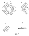
- microcontact structure as a planar two-dimensional structure in common processes for the preparation of micro-contact structures, e.g. can be produced on a silicon, silicone or polyimide base (see Fig. 1-4), in a second step for transport very compact folded or rolled and in a third step not only re-developed planar, but in the folded or rolled third dimension (see Fig 1-3), so that a three-dimensional structure is formed.
- microcontact structure communicates with other modules of the neuroprosthesis via signal paths.
- microcontact structure on the side facing the nerve tissue after implantation protruding structures, e.g. in the form of microelectrodes, sensors, cannulas, or nails, which are essential for the mechanical anchoring of the microcontact structure.
- An advantageous embodiment of the micro-contact structure is that for the purpose of transferring into a transport position by folding, rolling, or nesting of the interconnected parts, segments or islands from a predetermined planar basic position spring elements such. in the nature of spiral springs or coil springs, as well as elastic elements, e.g. pillow-like microstructures filled with gases or liquids and encased in an elastic material, and e.g. porous, sponge-like microstructures are stretched so that the automatic restoration of the basic position is prevented mainly by a transport lock.
- spring elements such. in the nature of spiral springs or coil springs, as well as elastic elements, e.g. pillow-like microstructures filled with gases or liquids and encased in an elastic material, and e.g. porous, sponge-like microstructures are stretched so that the automatic restoration of the basic position is prevented mainly by a transport lock.
- An advantageous embodiment of the transport lock is that the micro-contact structure in the transport position by a force-receiving bracket, or shell, or pinning is.
- An advantageous embodiment of the operation of the transport lock is that the transport lock is achieved at the implantation by using a suitable tool so that the transfer from the transport takes place in the basic position as a controlled movement. This is done in the case of Clamp, shell or pin preferably in that the forces are first taken up by an example pliers-like tool that subsequently removes the transport lock with another tool and that subsequently the transfer to the basic position using the pliers-like tool is controlled.
- the transfer of secured transport position in the basic position is carried out in a further advantageous embodiment in the case of realized by lowering temperature envelope or icing caused by movement blockage preferably characterized in that by a suitably shaped and controllable local heat source either as a separate tool or as an integrated element of the micro contact structure Positioning of the microcontact structure at the implantation site the mobility of its parts is restored by controlled heat supply.
- micro-contact structure is that the return transfer from operating position to basic position in the case of realized by lowering temperature envelope or icing generated by movement blockage preferably characterized in that by a suitably shaped and controllable local cold source (eg Peltier element) as an integrated Element of the micro-contact structure for the purpose of re-explantation the mobility of its parts is blocked by controlled heat extraction.
- a suitably shaped and controllable local cold source eg Peltier element
- a further advantageous embodiment of the device of a spatially adaptive micro-contact structure is that the structure in a collapsed Condition safely transported and implanted, unfolds itself by removal of the fuse by material properties and thereby assumes a previously embossed three-dimensional structure.
- a further advantageous embodiment of the device of a spatially adaptive microcontact structure is that the structure by the self-development takes on a form in which it can interlock with the tissue by raised micro-contacts (see Fig. 3).
- a further advantageous embodiment of the device of a spatially adaptive microcontact structure is that for the purpose of explantation, the shortened connections to the structure can be severed and the structure itself returns to a planar state by material properties, in which the teeth detach with the tissue ,
- a further advantageous embodiment of the device of a spatially adaptive micro-contact structure is that the structure by the teeth with the tissue requires no further attachment for a stationary implantation.
- a further advantageous embodiment of the method consists in that the microcontact structure is based on a multilayer substrate which has so-called memory properties with regard to the spatial arrangement of the microcontact structure.
- 4 shows a section through an advantageous 4-layered microcontact structure, in which the interaction between the microcontact structure and the nerve tissue is realized by electrical stimulation.
- the nerve tissue to be stimulated facing layer consists of the polymer P1 (polyimide) and contains penetrating electrodes of the metal M (platinum), which forms the subsequent layer. This is followed by another layer of the polymer P1 and a layer of the polymer P2 (polyurethane).
- the polymer P2 has the property of thermal expansion relative to P1 and the absorption of infrared radiation (IR), so that a defined volume expansion is effected by irradiation with IR light.
- IR infrared radiation
- the micro contact foil is deformed by focused irradiation at defined locations and adapted to the nerve tissue.
- the polymer P2 has the property of undergoing structural transitions in the electromagnetic radiation from the ultraviolet wavelength range, which lead to the contraction of the material.
- the compensation of the deformation previously achieved by IR light or the opposite deformation is effected by means of focused UV treatment, so that the detachment of the microcontact structure from the nerve tissue takes place. In this way, the re-explantation of the microcontact film is initiated.
Landscapes
- Health & Medical Sciences (AREA)
- Nuclear Medicine, Radiotherapy & Molecular Imaging (AREA)
- Animal Behavior & Ethology (AREA)
- Veterinary Medicine (AREA)
- Cardiology (AREA)
- Heart & Thoracic Surgery (AREA)
- Engineering & Computer Science (AREA)
- Biomedical Technology (AREA)
- Public Health (AREA)
- General Health & Medical Sciences (AREA)
- Radiology & Medical Imaging (AREA)
- Life Sciences & Earth Sciences (AREA)
- Neurosurgery (AREA)
- Neurology (AREA)
- Orthopedic Medicine & Surgery (AREA)
- Ophthalmology & Optometry (AREA)
- Prostheses (AREA)
- Electrotherapy Devices (AREA)
- Materials For Medical Uses (AREA)
Description
- Die Erfindung betrifft eine implantierbare Mikrokontaktstruktur für Retina-Implantate zur Behandlung von Funktionsstörungen des Nervensystems zum Zwecke der reversiblen Verankerung an Nervengewebe.
- Es sind mehrere Mikrokontaktstrukturen für teilweise implantierte Neuroprothesen bekannt, deren räumliche Mikrokontaktanordnung durch eine starre vorgeformte Fläche festgelegt ist, so z.B. in der Patentschrift
US 5,215,088 . - Es sind mehrere Mikrokontaktstrukturen für teilweise implantierte Neuroprothesen bekannt, deren räumliche Mikrokontaktanordnung durch eine teilweise elastische, biegsame vorgeformte Fläche festgelegt ist und sich durch die Art der Implantatbefestigung sowie durch passive Anpassung an die Gewebeform im Implantatbereich verändern kann, so in der
DE 4424753 A1 . - Die Herstellung einer solchen Mikrokontaktstruktur ist beispielsweise aus der folgenden Veröffentlichung bekannt:
- "Flexible, polyimide-based neural interfaces." Stieglitz T. Beutel H. Keller R. Schuettler M. Meyer J-U. Proceedings of the Seventh International Conference on Microelectronics for Neural, Fuzzy and Bio-Inspired Systems. IEEE Comput. Soc. 1999, pp.112-19. Los Alamitos, CA, USA.
- Eine Mikrokontakstruktur gemäß Oberbegriff des Anspruchs 1 ist aus
US-A- 5 919 220 bekannt. - An den bekannten Mikrokontaktstrukturen ist nachteilig, daß keine Vorrichtungen und Verfahren für eine Explantation der Mikrokontaktstruktur vorgesehen sind.
- Die bekannten Mikrokontaktstrukturen verfügen weiter nicht über Mechanismen, die die Anpassung der Mikrokontaktstruktur an die Form des zu kontaktierenden Gewebes vollziehen. Deswegen kann nicht sichergestellt werden, daß der Abstand zwischen den Mikroelektroden und den zu stimulierenden Neuronen des Nervengewebes minimal ist.
- Nachteilig an den bekannten Mikrokontaktstrukturen ist weiter, daß sie nicht über die Möglichkeit der selbsttätigen Befestigung der Mikrokontaktstruktur am Nervengewebe verfügen.
- Nachteilig an den gegenwärtig konzipierten bzw. verfügbaren Mikrokontaktstrukturen für epi-retinale Sehprothesen ist, daß diesen Merkmale fehlen, die die Einbringung in das Auge in räumlich komprimierter Form erlauben, und deshalb komplizierte chirurgische Techniken erforderlich sind. Diese Schwierigkeit wird sich in Zukunft verstärken, weil die räumlichen Abmessungen der Mikrokontaktstrukturen mit steigender Kontaktanzahl größer werden.
- Ferner fehlt den gegenwärtig konzipierten bzw. verfügbaren Mikrokontaktstrukturen für epi-retinale Sehprothesen die Möglichkeit, die Neurone der Retina, die den Bereich des schärfsten Sehens vermitteln, mit einer hohen Mikrokontaktdichte zu belegen, da sich solche Neurone im sog. parafovealen Zellkrater befinden, der sich durch eine räumliche Kraterstruktur auszeichnet.
- Es ist deshalb die Aufgabe der vorliegenden Erfindung, diese Nachteile zu beseitigen und eine Mikrokontaktstruktur zu offenbaren, die in komprimierter Form in den Körper einbringbar ist und reversibel am Nervengewebe verankert werden kann.
- Diese Aufgabe wird von einer Mikrokontaktstruktur mit dem Merkmalen des Anspruchs 1 gelöst.
- Die Mikrokontaktsstruktur gewährleistet einen guten Kontakt bzw. Wirkungszusammenhang mit Nervengewebe, da die implantierte Mikrokontaktstruktur relativ zueinander bewegliche Teilflächen umfaßt, die in mindestens zwei dauerhafte Vorzugsstellungen relativ zueinander gebracht werden können. und die während der Implantation in eine Vorzugsstellung zum Zwecke der mechanischen Verankerung mit dem zu kontaktierenden Nervengewebe gebracht sowie während der Explantation zur Lösung der Verankerung aus einer Vorzugsstellung in eine Andere gebracht werden können.
- Vorteilhafte Ausgestaltungen der räumlich adaptiven Mikrokontaktstruktur sind anhand der Fig. 1 bis Fig. 4 dargestellt.
- Eine vorteilhafte Ausgestaltung der Vorrichtung einer räumlich adaptiven Mikrokontaktstruktur für Neuroprothesen zur Implantation an Nervengewebe besteht darin, daß die Mikrokontaktstruktur als eine planare zweidimensionale Struktur in gängigen Verfahren zur Herstellung von Mikrokontaktstrukturen z.B. auf Silizium-, Silikon- oder Polyimid-Basis hergestellt werden kann (s. Fig. 1-4), in einem zweiten Schritt für Transportzwecke sehr kompakt gefaltet oder gerollt werden kann und in einem dritten Schritt nicht nur wieder planar entfaltet, sondern in die dritte Dimension gefaltet oder gerollt wird (s. Fig 1-3), so daß eine dreidimensionale Struktur entsteht.
- Eine vorteilhafte Ausgestaltung der Mikrokontaktstruktur besteht darin, daß sie mit weiteren Modulen der Neuroprothese über Signalwege in Verbindung steht.
- Eine vorteilhafte Ausgestaltung der Mikrokontaktstruktur besteht darin, daß auf der nach Implantation dem Nervengewebe zugewandten Seite hervorstehende Strukturen z.B. in Form von Mikroelektroden, Sensoren, Kanülen, oder Nägeln vorgesehen sind, die für die mechanische Verankerung der Mikrokontaktstruktur wesentlich sind.
- Eine vorteilhafte Ausgestaltung der Mikrokontaktstruktur besteht darin, daß zum Zwecke der Überführung in eine Transportstellung durch Faltung, Rollung, oder Schachtelung der miteinander verbundenen Teile, Segmente bzw. Inseln aus einer vorgegebenen planaren Grundstellung Federelemente wie z.B. nach Art von Biegefedern oder Spiralfedern sowie elastische Elemente wie z.B. mit Gasen oder Flüssigkeiten gefüllte und mit einem elastischen Material umhüllte kissenähnliche Mikrostrukturen sowie z.B. poröse, schwammähnliche Mikrostrukturen gespannt werden so daß die automatische Wiederherstellung der Grundstellung hauptsächlich durch eine Transportsicherung verhindert wird.
- Eine vorteilhafte Ausgestaltung der Transportsicherung besteht darin, daß die Mikrokontaktstruktur in der Transportstellung durch eine die Kräfte aufnehmende Klammer, oder Hülle, oder Verstiftung wird.
- Eine vorteilhafte Ausgestaltung der Bedienung der Transportsicherung besteht darin, daß die Transportsicherung am Implantationsort durch Verwendung eines geeigneten Werkzeuges so gelöst wird, daß die Überführung aus der Transport- in die Grundstellung als kontrollierte Bewegung erfolgt. Dies erfolgt im Falle von Klammer, Hülle oder Stift vorzugsweise dadurch, daß die Kräfte zunächst von einem z.B. zangenähnlichen Werkzeug aufgenommen werden, daß anschließend die Transportsicherung mit einem weiteren Werkzeug entfernt und daß anschließend die Überführung in die Grundstellung mit Hilfe des zangenähnlichen Werkzeuges kontrolliert wird.
- Die Überführung von gesicherter Transportstellung in Grundstellung erfolgt in einer weiteren vorteilhaften Ausgestaltung im Falle einer durch Temperaturabsenkung realisierten Hülle bzw. durch Vereisung erzeugten Bewegungsblockade vorzugsweise dadurch, daß durch eine geeignet geformte und steuerbare lokale Wärmequelle entweder als separates Werkzeug oder als integriertes Element der der Mikrokontaktstruktur nach Positionierung der Mikrokontaktstruktur am Implantationsort die Beweglichkeit seiner Teile durch kontrollierte Wärmezufuhr wieder hergestellt wird.
- Eine vorteilhafte Ausgestaltung der Mikrokontaktstruktur besteht darin, daß die Rück-Überführung von Betriebsstellung in Grundstellung im Falle einer durch Temperaturabsenkung realisierten Hülle bzw. durch Vereisung erzeugten Bewegungsblockade vorzugsweise dadurch, daß durch eine geeignet geformte und steuerbare lokale Kältequelle (z.B. Peltier-Element) als integriertes Element der der Mikrokontaktstruktur zum Zwecke der Re-Explantation die Beweglichkeit seiner Teile durch kontrollierten Wärmeentzug blockiert wird.
- Eine weitere vorteilhafte Ausgestaltung der Vorrichtung einer räumlich adaptiven Mikrokontaktstruktur besteht darin, daß die Struktur, die in einem zusammengefalteten Zustand gesichert transportiert und implantiert wird, sich bei Entfernung der Sicherung durch Materialeigenschaften selbst entfaltet und dadurch eine vorher eingeprägte dreidimensionale Struktur annimmt.
- Eine weitere vorteilhafte Ausgestaltung der Vorrichtung einer räumlich adaptiven Mikrokontaktstruktur besteht darin, daß die Struktur durch die Selbstentfaltung eine Form annimmt, in der sie sich durch erhabene Mikrokontakte mit dem Gewebe verzahnen kann (s. Fig 3).
- Eine weitere vorteilhafte Ausgestaltung der Vorrichtung einer räumlich adaptiven Mikrokontaktstruktur besteht darin, daß zum Zwecke der Explantation die verkürzten Verbindungen an der Struktur durchtrennt werden können und sich die Struktur durch Materialeigenschaften selbst wieder in einen planaren Zustand bringt, in dem sich die Verzahnungen mit dem Gewebe lösen.
- Eine weitere vorteilhafte Ausgestaltung der Vorrichtung einer räumlich adaptiven Mikrokontaktstruktur besteht darin, daß die Struktur durch die Verzahnung mit dem Gewebe keine weitere Befestigung für eine ortsstabile Implantation benötigt.
- Eine weitere vorteilhafte Ausgestaltung des Verfahrens besteht darin, daß die Mikrokontaktstruktur auf einem mehrschichtig aufgebauten Substrat basiert, das über sogenannte Memory-Eigenschaften hinsichtlich der räumlichen Anordnung der Mikrokontaktstruktur verfügt. Die Fig. 4 zeigt einen Schnitt durch eine vorteilhafte 4-schichtige Mikrokontaktstruktur, bei der der Wirkungszusammenhang zwischen der Mikrokontaktstruktur und dem Nervengewebe durch elektrische Stimulation realisiert wird. Die dem zu stimulierenden Nervengewebe zugewandte Schicht besteht aus dem Polymer P1 (Polyimid) und enthält penetrierende Elektroden aus dem Metall M (Platin), das die anschließende Schicht bildet. Es folgt eine weitere Schicht des Polymers P1 und eine Schicht des Polymers P2 (Polyurethan). Das Polymer P2 hat die Eigenschaft der thermischen Ausdehnung relativ zu P1 und der Absorption von infraroter Strahlung (IR), so daß durch Bestrahlung mit IR-Licht eine definierte Volumenexpansion bewirkt wird.
- Auf diese Weise wird die Mikrokontaktfolie durch fokussierte Bestrahlung an definierten Stellen verformt und an das Nervengewebe angepaßt. Weiterhin besitzt das Polymer P2 die Eigenschaft, bei der elektromagnetischen Bestrahlung aus dem ultravioletten Wellenlängenbereich strukturelle Übergänge zu vollziehen, die zur Kontraktion des Materials führen. Dadurch wird mittels fokussierter UV-Behandlung die Kompensation der zuvor durch IR-Licht erzielten Verformung bzw. die entgegengesetzte Verformung bewirkt, so daß die Ablösung der Mikrokontaktstruktur vom Nervengewebe erfolgt. Auf diese Weise wird die Re-Explantation der Mikrokontaktfolie eingeleitet.
Claims (16)
- Implantierbare Mikrokontaktstruktur für Neuroprothesen zur Kontaktierung von Nervengewebe, mit einer Anzahl von Kontaktelementen, die auf wenigstens einem flächenhaften Träger ausgebildet sind, der wenigstens zwei relativ zueinander bewegliche Bereiche aufweist, die wenigstens zwei Vorzugsstellungen, nämlich eine Grundstellung und eine Betriebsstellung einnehmen können, wobei die Mikrokontaktstruktur für den Transport von oder zu einem Implantationsort in eine kompakte Grundstellung einstellbar ist, wobei die räumliche Ausdehnung der Mikrokontaktstruktur durch Faltung, Schachtelung oder Rollung der relativ zueinander beweglichen Bereiche verringert wird, und die Mikrokontaktstruktur zur mechanischen Verankerung sowie zur Kontaktierung des Nervengewebes am Implantationsort in eine Betriebsstellung mit einer planaren oder dreidimensionalen Struktur einstellbar ist, wobei die räumliche Ausdehnung der Mikrokontaktstruktur durch Öffnen der Faltung, Schachtelung oder Rollung der relativ zueinander beweglichen Bereiche vergrößert wird, dadurch gekennzeichnet, daß die Mikrokontaktstruktur eine Mikrokontaktstruktur zur retinalen Implantation für ein Retina-Implantat ist.
- Mikrokontaktstruktur nach Anspruch 1 dadurch gekennzeichnet, dass die Mikrokontaktstruktur ein mehrschichtig aufgebautes Substrat umfasst, das Memory-Materialeigenschaften hinsichtlich der räumlichen Anordnung der Mikrokontaktstruktur aufweist.
- Mikrokontaktstruktur nach Anspruch 2 dadurch gekennzeichnet, dass ein Wechsel oder eine Veränderung der Vorzugsstellungen der Mikrokontaktstruktur aufgrund der Memory-Materialeigenschaften der Mikrokontaktstruktur und durch externe Einwirkung vor der Implantation, durch eine externen Eingriff oder durch externe Signale aktiv steuerbar ist.
- Mikrokontaktstruktur nach einem der vorhergehenden Ansprüche dadurch gekennzeichnet, dass die kompakte Grundstellung der Mikrokontaktstruktur für den chirurgischen Transport durch eine Transportsicherung gesichert wird, die durch einen externen Eingriff lösbar ist.
- Mikrokontaktstruktur nach Anspruch 4 dadurch gekennzeichnet, dass die Transportsicherung der Mikrokontaktstruktur durch eine Klammer, Hülle oder Verstiftung ausgebildet ist.
- Mikrokontaktstruktur nach einem der Ansprüche 4 oder 5 dadurch gekennzeichnet, dass sich die Mikrokontaktstruktur nach Entfernung der Transportsicherung aufgrund seiner Memory-Materialeigenschaften selbsttätig entfaltet und eine vorher im Material der Mikrokontaktstruktur eingeprägte dreidimensionale Struktur annimmt.
- Mikrokontaktstruktur nach einem vorhergehenden Ansprüche dadurch gekennzeichnet, dass die Mikrokontaktstruktur erhabene Mikrokontakte aufweist, die sich in der Betriebsstellung mit dem zu kontaktierendem Gewebe verzahnen.
- Mikrokontaktstruktur nach einem der vorhergehenden Ansprüche, dadurch gekennzeichnet, dass das Öffnen der Faltung, Schachtelung oder Rollung der relativ zueinander beweglichen Bereiche der Mikrokontaktstruktur nach dem Lösen der Transportsicherung aus der kompakten Grundstellung in eine zur Vorbereitung der mechanischen Verankerung geeignete Vorzugsstellung durch Freisetzung von Federkräften, molekularen Konformationsänderungen, pneumatischen Kräften, hydraulischen Kräften oder/und elektromagnetischen Kräften an den Übergängen zwischen den beweglichen Bereiche der Mikrokontaktstruktur selbsttätig erfolgt.
- Mikrokontaktstruktur nach einem der vorhergehenden Ansprüche dadurch gekennzeichnet, dass der Wechsel oder die Veränderung einer Vorzugsstellung der Mikrokontaktstruktur zum Zwecke seiner mechanischen Verankerung am Nervengewebe durch eine extern festgelegte Einwirkung in einem zeitlich kontrollierten Ablauf bezüglich Bewegung und Kraft einstellbar ist.
- Mikrokontaktstruktur nach einem der vorhergehenden Ansprüche dadurch gekennzeichnet, dass der Wechsel oder die Veränderung einer Vorzugsstellung der Mikrokontaktstruktur zum Zwecke der Optimierung von Kontakt bzw. Wirkungszusammenhang mit dem Nervengewebe durch eine extern festgelegte Einwirkung in einem zeitlich kontrollierten Ablauf bezüglich Bewegung und Kraft einstellbar ist.
- Mikrokontaktstruktur nach einem der vorhergehenden Ansprüche dadurch gekennzeichnet, dass der Wechsel oder die Veränderung einer Vorzugsstellung der Mikrokontaktstruktur über eine chirurgische Vorrichtung oder über die Übermittlung von elektromagnetischen Signalen, Licht oder Ultraschall an die Mikrokontaktstruktur einstellbar ist.
- Mikrokontaktstruktur nach einem der vorhergehenden Ansprüche, dadurch gekennzeichnet, dass der Wechsel der für die mechanische Verankerung der Mikrokontaktstruktur am Nervengewebe gewählten Vorzugsstellung zum Zwecke der Re-Explantation durch eine extern festgelegte Einwirkung in einem zeitlich kontrollierten Ablauf bezüglich Bewegung und Kraft dosiert einstellbar ist.
- Mikrokontaktstruktur nach einem der vorhergehenden Ansprüche dadurch gekennzeichnet, dass die Mikrokontaktstruktur aus einem mehrschichtigen Substrat aufgebaut ist, wobei eine dem zu stimulierenden Nervengewebe zugewandte Schicht aus einem ersten Polymer hergestellt ist und penetrierende Elektroden aus Metall beinhaltet, das die anschließende Schicht bildet, eine weitere Schicht aus dem ersten Polymer und eine Schicht aus einem zweiten Polymer hergestellt ist.
- Mikrokontaktstruktur nach Anspruch 13 dadurch gekennzeichnet, dass das zweite Polymer die Eigenschaft einer thermischen Ausdehnung relativ zum ersten Polymer und der Absorption von infraroter Strahlung aufweist, so dass durch Bestrahlung mit infraroter Strahlung eine definierte Volumenexpansion der Mikrokontaktstruktur einstellbar ist.
- Mikrokontaktstruktur nach einem der Ansprüche 13 oder 14 dadurch gekennzeichnet, dass aufgrund der Materialeigenschaften der Mikrokontaktstruktur durch elektromagnetische Bestrahlung im ultravioletten Wellenlängenbereich strukturelle Übergänge im Material der Mikrokontaktstruktur einstellbar sind, die eine Volumenkontraktion der Mikrokontaktstruktur bewirken.
- Mikrokontaktstruktur nach einem der Ansprüche 13 bis 15 dadurch gekennzeichnet, dass die Mikrokontaktstruktur aufgrund seiner Materialeigenschaften durch fokussierte Bestrahlung mit Infrarot-Licht an definierten Stellen verformbar und an das zu kontaktierende Nervengewebe anpassbar ist.
Applications Claiming Priority (3)
| Application Number | Priority Date | Filing Date | Title |
|---|---|---|---|
| DE10020846A DE10020846A1 (de) | 2000-04-28 | 2000-04-28 | Mikrokontaktstruktur für Neuroprothesen zur Implantation an Nervengewebe und Verfahren hierzu |
| DE10020846 | 2000-04-28 | ||
| PCT/EP2000/012713 WO2001083025A1 (de) | 2000-04-28 | 2000-12-14 | Mikrokontaktstruktur für neuroprothesen zur implantation an nervengewebe und verfahren hierzu |
Publications (2)
| Publication Number | Publication Date |
|---|---|
| EP1276537A1 EP1276537A1 (de) | 2003-01-22 |
| EP1276537B1 true EP1276537B1 (de) | 2007-09-05 |
Family
ID=7640207
Family Applications (1)
| Application Number | Title | Priority Date | Filing Date |
|---|---|---|---|
| EP00991189A Expired - Lifetime EP1276537B1 (de) | 2000-04-28 | 2000-12-14 | Mikrokontaktstruktur für neuroprothesen zur implantation an nervengewebe |
Country Status (8)
| Country | Link |
|---|---|
| US (1) | US6970746B2 (de) |
| EP (1) | EP1276537B1 (de) |
| AT (1) | ATE372144T1 (de) |
| AU (1) | AU2001231589A1 (de) |
| DE (2) | DE10020846A1 (de) |
| ES (1) | ES2292498T3 (de) |
| TW (1) | TW478933B (de) |
| WO (1) | WO2001083025A1 (de) |
Families Citing this family (33)
| Publication number | Priority date | Publication date | Assignee | Title |
|---|---|---|---|---|
| DE10060029A1 (de) * | 2000-12-01 | 2002-06-13 | Intelligent Implants Gmbh | Lösbare Implantathalterung |
| DE10120908A1 (de) | 2001-04-28 | 2002-10-31 | Td Verwaltungs Gmbh | Mikrokontaktstruktur zur Implantation bei einem Säugetier, insbesondere bei einem Menschen |
| WO2004038758A2 (en) * | 2002-07-19 | 2004-05-06 | Arizona Board Of Regents Acting For And On Behalf Of Arizona State University | Flexible integrated head-stage for neural interface |
| US8014878B2 (en) | 2005-04-28 | 2011-09-06 | Second Sight Medical Products, Inc. | Flexible circuit electrode array |
| US8131375B2 (en) * | 2003-03-21 | 2012-03-06 | Second Sight Medical Products, Inc. | Trans-retinal flexible circuit electrode array |
| US8260428B2 (en) * | 2003-05-01 | 2012-09-04 | California Institute Of Technology | Method and system for training a visual prosthesis |
| US7321796B2 (en) * | 2003-05-01 | 2008-01-22 | California Institute Of Technology | Method and system for training a visual prosthesis |
| WO2004112192A2 (en) * | 2003-06-12 | 2004-12-23 | Tereza Miguel Meneguim | Connecting device for nerve-cords |
| US20050021117A1 (en) * | 2003-07-21 | 2005-01-27 | Jiping He | Flexible integrated head-stage for neural interface |
| US8068913B2 (en) | 2004-12-03 | 2011-11-29 | Second Sight Medical Products, Inc. | Visual prosthesis for improved circadian rhythms and method of improving the circadian rhythms |
| EP1723983B1 (de) * | 2005-05-20 | 2013-07-10 | Imec | Sonde für die elektrische Stimulation und Bestimmung der Aktivität von erregbaren Zellen |
| EP2380625A1 (de) * | 2005-09-19 | 2011-10-26 | Second Sight Medical Products, Inc. | Transretinales flexibles Schaltungselektrodenarray |
| US7877866B1 (en) | 2005-10-26 | 2011-02-01 | Second Sight Medical Products, Inc. | Flexible circuit electrode array and method of manufacturing the same |
| US20070198066A1 (en) * | 2005-11-03 | 2007-08-23 | Greenberg Robert J | Method and apparatus for visual neural stimulation |
| US8190266B2 (en) * | 2006-02-15 | 2012-05-29 | Dohey Eye Institute | Wide-field retinal prosthesis |
| US8126538B2 (en) * | 2006-06-06 | 2012-02-28 | Cardiac Pacemakers, Inc. | Method and apparatus for introducing endolymphatic instrumentation |
| US7894906B2 (en) * | 2006-06-06 | 2011-02-22 | Cardiac Pacemakers, Inc. | Amelioration of chronic pain by endolymphatic stimulation |
| US7526337B2 (en) * | 2006-06-06 | 2009-04-28 | Cardiac Pacemakers, Inc. | Method and device for lymphatic system monitoring |
| US7734341B2 (en) | 2006-06-06 | 2010-06-08 | Cardiac Pacemakers, Inc. | Method and apparatus for gastrointestinal stimulation via the lymphatic system |
| US20070282376A1 (en) | 2006-06-06 | 2007-12-06 | Shuros Allan C | Method and apparatus for neural stimulation via the lymphatic system |
| US8905999B2 (en) | 2006-09-01 | 2014-12-09 | Cardiac Pacemakers, Inc. | Method and apparatus for endolymphatic drug delivery |
| US9037244B2 (en) * | 2007-02-13 | 2015-05-19 | Virender K. Sharma | Method and apparatus for electrical stimulation of the pancreatico-biliary system |
| DE102007013660A1 (de) | 2007-03-19 | 2008-09-25 | Genesis Adaptive Systeme Deutschland Gmbh | Exoprothese |
| EP2326386B1 (de) * | 2008-09-26 | 2015-11-18 | Pixium Vision SA | Elektrodenreihe und herstellungsverfahren dafür |
| US9079028B2 (en) | 2008-10-09 | 2015-07-14 | Virender K. Sharma | Method and apparatus for stimulating the vascular system |
| US10603489B2 (en) | 2008-10-09 | 2020-03-31 | Virender K. Sharma | Methods and apparatuses for stimulating blood vessels in order to control, treat, and/or prevent a hemorrhage |
| US8612020B2 (en) * | 2008-10-31 | 2013-12-17 | Medtronic, Inc. | Implantable therapeutic nerve stimulator |
| EP2477467B1 (de) | 2011-01-14 | 2017-07-26 | Second Sight Medical Products, Inc. | Verfahren zur Herstellung einer elektrodenanordnung einer flexiblen Schaltung |
| US8516568B2 (en) | 2011-06-17 | 2013-08-20 | Elliot D. Cohen | Neural network data filtering and monitoring systems and methods |
| DE102014014927A1 (de) | 2014-10-07 | 2016-04-07 | Neuroloop GmbH | Implantierbare Elektrodenanordnung |
| US20160331326A1 (en) * | 2015-02-13 | 2016-11-17 | National University Of Singapore | Flexible neural strip electrodes, flexible neural ribbon electrodes and compartment based embedded nerve tissue electrode interfaces for peripheral nerves |
| DE102018207709A1 (de) * | 2018-05-17 | 2019-11-21 | Neuroloop GmbH | Vorrichtung zur extravasalen oder extraneuronalen Befestigung eines medizinischen Implantats in Art einer Wickelmanschette |
| KR102408304B1 (ko) * | 2020-01-23 | 2022-06-14 | 재단법인대구경북과학기술원 | 변형 가능한 망막 전극 장치 |
Family Cites Families (15)
| Publication number | Priority date | Publication date | Assignee | Title |
|---|---|---|---|---|
| US3738368A (en) * | 1970-12-14 | 1973-06-12 | R Avery | Implantable electrodes for the stimulation of the sciatic nerve |
| US3774618A (en) * | 1972-07-03 | 1973-11-27 | Avery Labor Inc | Implantable nerve stimulation electrode |
| US4424753A (en) | 1982-08-05 | 1984-01-10 | Down River International, Inc. | Pallet of composite construction |
| US4628933A (en) * | 1985-07-23 | 1986-12-16 | Michelson Robin P | Method and apparatus for visual prosthesis |
| US4969468A (en) * | 1986-06-17 | 1990-11-13 | Alfred E. Mann Foundation For Scientific Research | Electrode array for use in connection with a living body and method of manufacture |
| US4940065A (en) * | 1989-01-23 | 1990-07-10 | Regents Of The University Of California | Surgically implantable peripheral nerve electrode |
| US5024223A (en) * | 1989-08-08 | 1991-06-18 | Chow Alan Y | Artificial retina device |
| US5215088A (en) * | 1989-11-07 | 1993-06-01 | The University Of Utah | Three-dimensional electrode device |
| US5324322A (en) * | 1992-04-20 | 1994-06-28 | Case Western Reserve University | Thin film implantable electrode and method of manufacture |
| US5476494A (en) * | 1992-09-11 | 1995-12-19 | Massachusetts Institute Of Technology | Low pressure neural contact structure |
| US5897583A (en) * | 1994-07-13 | 1999-04-27 | Fraunhofer Gesellschaft Zur Forderung Der Angewandten Forschung E.V. | Flexible artificial nerve plates |
| DE4424753B4 (de) * | 1994-07-13 | 2004-07-29 | Fraunhofer-Gesellschaft zur Förderung der angewandten Forschung e.V. | Retina-Implantat |
| DE4433111A1 (de) * | 1994-09-16 | 1996-03-21 | Fraunhofer Ges Forschung | Cuff-Elektrode |
| US5827184A (en) * | 1995-12-29 | 1998-10-27 | Minnesota Mining And Manufacturing Company | Self-packaging bioelectrodes |
| US6368349B1 (en) * | 2000-11-21 | 2002-04-09 | Massachusetts Institute Of Technology | Inflatable neural prosthesis |
-
2000
- 2000-04-28 DE DE10020846A patent/DE10020846A1/de not_active Ceased
- 2000-12-14 AU AU2001231589A patent/AU2001231589A1/en not_active Abandoned
- 2000-12-14 WO PCT/EP2000/012713 patent/WO2001083025A1/de not_active Ceased
- 2000-12-14 AT AT00991189T patent/ATE372144T1/de active
- 2000-12-14 ES ES00991189T patent/ES2292498T3/es not_active Expired - Lifetime
- 2000-12-14 DE DE50014634T patent/DE50014634D1/de not_active Expired - Lifetime
- 2000-12-14 EP EP00991189A patent/EP1276537B1/de not_active Expired - Lifetime
-
2001
- 2001-01-26 US US09/771,283 patent/US6970746B2/en not_active Expired - Lifetime
- 2001-02-01 TW TW089127777A patent/TW478933B/zh not_active IP Right Cessation
Non-Patent Citations (1)
| Title |
|---|
| None * |
Also Published As
| Publication number | Publication date |
|---|---|
| US6970746B2 (en) | 2005-11-29 |
| TW478933B (en) | 2002-03-11 |
| DE50014634D1 (de) | 2007-10-18 |
| US20010037061A1 (en) | 2001-11-01 |
| ES2292498T3 (es) | 2008-03-16 |
| AU2001231589A1 (en) | 2001-11-12 |
| WO2001083025A1 (de) | 2001-11-08 |
| DE10020846A1 (de) | 2001-12-06 |
| EP1276537A1 (de) | 2003-01-22 |
| ATE372144T1 (de) | 2007-09-15 |
Similar Documents
| Publication | Publication Date | Title |
|---|---|---|
| EP1276537A1 (de) | Mikrokontaktstruktur für neuroprothesen zur implantation an nervengewebe und verfahren hierzu | |
| EP0928212B1 (de) | Flexible künstliche nervenplatte | |
| EP1986733B1 (de) | Vorrichtung mit flexiblem mehrschichtsystem zur kontaktierung oder elektrostimulation von lebenden gewebezellen oder nerven | |
| US8099172B2 (en) | Spinal cord stimulation paddle lead and method of making the same | |
| EP0843574B1 (de) | Cuff-elektrode | |
| WO2006116968A2 (de) | Biostabile neuroelektrode | |
| US20060042830A1 (en) | Flexible multi-level cable | |
| US20130144145A1 (en) | Implantable neural tissue reporting probe and methods of manufacturing and implanting same | |
| US10603505B2 (en) | Implantable neural probe | |
| US10426968B2 (en) | Neural modulation system | |
| DE602005002498T2 (de) | Gehirnimplantat | |
| EP1349608A1 (de) | Siebelektrode zur anbindung an einen nervenstumpf | |
| US10449382B2 (en) | Implantable neural modulation device | |
| EP2033682A1 (de) | Flexible Sehprothese und ein Verfahren zur Herstellung einer flexiblen Sehprothese | |
| DE10063612C2 (de) | Mikrosystem zur Kontrolle der Wirkstoffabgabe aus einem Wirkstoffreservoir sowie Implantat mit Mikrosystem | |
| Stieglitz et al. | Biomedical microdevices for neural implants | |
| EP1407801B1 (de) | Elektromedizinisches Implantat zur interkardialen Herztherapie | |
| JP4469926B2 (ja) | カフ型アクチュエータおよびカフ型インタフェース装置 | |
| DE102019006709A1 (de) | Kontaktierung flexibler Elektroden | |
| Rincón Montes | Development, characterization, and application of intraretinal implants | |
| Montes | V. Development, Characterization, and Application of Intraretinal Implants | |
| DE112011101149T5 (de) | Verfahren zur Herstellung eines implantierbaren Pulsgenerators mit Drahtverbindungen zu Durchführstrukturen und implantierbarer Pulsgenerator | |
| DE102024110006A1 (de) | Mehrsondensysteme für elektrogenes Gewebe, Verfahren zu deren Herstellung und Verwendungen | |
| WO2008128723A1 (de) | Implantierbares system zur anregung von neuronen | |
| EP1790379A1 (de) | Retina Implantat zur elektrischen Stimulation der Netzhaut |
Legal Events
| Date | Code | Title | Description |
|---|---|---|---|
| PUAI | Public reference made under article 153(3) epc to a published international application that has entered the european phase |
Free format text: ORIGINAL CODE: 0009012 |
|
| AK | Designated contracting states |
Kind code of ref document: A1 Designated state(s): AT BE CH CY DE DK ES FI FR GB GR IE IT LI LU MC NL PT SE TR |
|
| 17P | Request for examination filed |
Effective date: 20021113 |
|
| 17Q | First examination report despatched |
Effective date: 20040820 |
|
| RAP1 | Party data changed (applicant data changed or rights of an application transferred) |
Owner name: INTELLIGENT ACQUISITION, LLC |
|
| GRAP | Despatch of communication of intention to grant a patent |
Free format text: ORIGINAL CODE: EPIDOSNIGR1 |
|
| RTI1 | Title (correction) |
Free format text: MICROCONTACT STRUCTURE FOR NEUROPROSTHESES FOR IMPLANTING ON NERVE TISSUE |
|
| RAP1 | Party data changed (applicant data changed or rights of an application transferred) |
Owner name: IMI INTELLIGENT MEDICAL IMPLANTS AG |
|
| GRAS | Grant fee paid |
Free format text: ORIGINAL CODE: EPIDOSNIGR3 |
|
| GRAA | (expected) grant |
Free format text: ORIGINAL CODE: 0009210 |
|
| AK | Designated contracting states |
Kind code of ref document: B1 Designated state(s): AT BE CH CY DE DK ES FI FR GB GR IE IT LI LU MC NL PT SE TR |
|
| REG | Reference to a national code |
Ref country code: GB Ref legal event code: FG4D Free format text: NOT ENGLISH |
|
| REG | Reference to a national code |
Ref country code: CH Ref legal event code: EP |
|
| REF | Corresponds to: |
Ref document number: 50014634 Country of ref document: DE Date of ref document: 20071018 Kind code of ref document: P |
|
| REG | Reference to a national code |
Ref country code: IE Ref legal event code: FG4D Free format text: LANGUAGE OF EP DOCUMENT: GERMAN |
|
| REG | Reference to a national code |
Ref country code: CH Ref legal event code: NV Representative=s name: PATENTANWALTSKANZLEI NUECKEL |
|
| GBT | Gb: translation of ep patent filed (gb section 77(6)(a)/1977) |
Effective date: 20071129 |
|
| PG25 | Lapsed in a contracting state [announced via postgrant information from national office to epo] |
Ref country code: FI Free format text: LAPSE BECAUSE OF FAILURE TO SUBMIT A TRANSLATION OF THE DESCRIPTION OR TO PAY THE FEE WITHIN THE PRESCRIBED TIME-LIMIT Effective date: 20070905 |
|
| REG | Reference to a national code |
Ref country code: ES Ref legal event code: FG2A Ref document number: 2292498 Country of ref document: ES Kind code of ref document: T3 |
|
| REG | Reference to a national code |
Ref country code: IE Ref legal event code: FD4D |
|
| ET | Fr: translation filed | ||
| PG25 | Lapsed in a contracting state [announced via postgrant information from national office to epo] |
Ref country code: GR Free format text: LAPSE BECAUSE OF FAILURE TO SUBMIT A TRANSLATION OF THE DESCRIPTION OR TO PAY THE FEE WITHIN THE PRESCRIBED TIME-LIMIT Effective date: 20071206 |
|
| PG25 | Lapsed in a contracting state [announced via postgrant information from national office to epo] |
Ref country code: PT Free format text: LAPSE BECAUSE OF FAILURE TO SUBMIT A TRANSLATION OF THE DESCRIPTION OR TO PAY THE FEE WITHIN THE PRESCRIBED TIME-LIMIT Effective date: 20080206 Ref country code: IE Free format text: LAPSE BECAUSE OF FAILURE TO SUBMIT A TRANSLATION OF THE DESCRIPTION OR TO PAY THE FEE WITHIN THE PRESCRIBED TIME-LIMIT Effective date: 20070905 |
|
| BERE | Be: lapsed |
Owner name: IMI INTELLIGENT MEDICAL IMPLANTS A.G. Effective date: 20071231 |
|
| PG25 | Lapsed in a contracting state [announced via postgrant information from national office to epo] |
Ref country code: SE Free format text: LAPSE BECAUSE OF FAILURE TO SUBMIT A TRANSLATION OF THE DESCRIPTION OR TO PAY THE FEE WITHIN THE PRESCRIBED TIME-LIMIT Effective date: 20071205 |
|
| PLBE | No opposition filed within time limit |
Free format text: ORIGINAL CODE: 0009261 |
|
| STAA | Information on the status of an ep patent application or granted ep patent |
Free format text: STATUS: NO OPPOSITION FILED WITHIN TIME LIMIT |
|
| PG25 | Lapsed in a contracting state [announced via postgrant information from national office to epo] |
Ref country code: MC Free format text: LAPSE BECAUSE OF NON-PAYMENT OF DUE FEES Effective date: 20071231 Ref country code: DK Free format text: LAPSE BECAUSE OF FAILURE TO SUBMIT A TRANSLATION OF THE DESCRIPTION OR TO PAY THE FEE WITHIN THE PRESCRIBED TIME-LIMIT Effective date: 20070905 |
|
| 26N | No opposition filed |
Effective date: 20080606 |
|
| PG25 | Lapsed in a contracting state [announced via postgrant information from national office to epo] |
Ref country code: BE Free format text: LAPSE BECAUSE OF NON-PAYMENT OF DUE FEES Effective date: 20071231 |
|
| PG25 | Lapsed in a contracting state [announced via postgrant information from national office to epo] |
Ref country code: CY Free format text: LAPSE BECAUSE OF FAILURE TO SUBMIT A TRANSLATION OF THE DESCRIPTION OR TO PAY THE FEE WITHIN THE PRESCRIBED TIME-LIMIT Effective date: 20070905 |
|
| REG | Reference to a national code |
Ref country code: CH Ref legal event code: PCAR Free format text: PATENTANWALTSKANZLEI NUECKEL;WEINBERGLISTRASSE 4;6005 LUZERN (CH) |
|
| PG25 | Lapsed in a contracting state [announced via postgrant information from national office to epo] |
Ref country code: LU Free format text: LAPSE BECAUSE OF NON-PAYMENT OF DUE FEES Effective date: 20071214 |
|
| PG25 | Lapsed in a contracting state [announced via postgrant information from national office to epo] |
Ref country code: TR Free format text: LAPSE BECAUSE OF FAILURE TO SUBMIT A TRANSLATION OF THE DESCRIPTION OR TO PAY THE FEE WITHIN THE PRESCRIBED TIME-LIMIT Effective date: 20070905 |
|
| REG | Reference to a national code |
Ref country code: CH Ref legal event code: PUE Owner name: PIXIUM VISION SA, FR Free format text: FORMER OWNER: IMI INTELLIGENT MEDICAL IMPLANTS AG, CH |
|
| REG | Reference to a national code |
Ref country code: DE Ref legal event code: R082 Ref document number: 50014634 Country of ref document: DE Representative=s name: GRAF VON STOSCH PATENTANWALTSGESELLSCHAFT MBH, DE |
|
| REG | Reference to a national code |
Ref country code: ES Ref legal event code: PC2A Owner name: PIXIUM VISION SA Effective date: 20131204 |
|
| REG | Reference to a national code |
Ref country code: GB Ref legal event code: 732E Free format text: REGISTERED BETWEEN 20131205 AND 20131211 |
|
| REG | Reference to a national code |
Ref country code: DE Ref legal event code: R081 Ref document number: 50014634 Country of ref document: DE Owner name: PIXIUM VISION SA, FR Free format text: FORMER OWNER: IMI INTELLIGENT MEDICAL IMPLANTS AG, ZUG, CH Effective date: 20131120 Ref country code: DE Ref legal event code: R082 Ref document number: 50014634 Country of ref document: DE Representative=s name: GRAF VON STOSCH PATENTANWALTSGESELLSCHAFT MBH, DE Effective date: 20131120 |
|
| REG | Reference to a national code |
Ref country code: FR Ref legal event code: TP Owner name: PIXIUM VISION SA, FR Effective date: 20140227 |
|
| REG | Reference to a national code |
Ref country code: NL Ref legal event code: SD Effective date: 20140723 |
|
| REG | Reference to a national code |
Ref country code: FR Ref legal event code: PLFP Year of fee payment: 16 |
|
| PGFP | Annual fee paid to national office [announced via postgrant information from national office to epo] |
Ref country code: CH Payment date: 20151222 Year of fee payment: 16 |
|
| PGFP | Annual fee paid to national office [announced via postgrant information from national office to epo] |
Ref country code: AT Payment date: 20151217 Year of fee payment: 16 Ref country code: ES Payment date: 20151218 Year of fee payment: 16 Ref country code: NL Payment date: 20151221 Year of fee payment: 16 |
|
| PGFP | Annual fee paid to national office [announced via postgrant information from national office to epo] |
Ref country code: IT Payment date: 20151222 Year of fee payment: 16 |
|
| REG | Reference to a national code |
Ref country code: FR Ref legal event code: PLFP Year of fee payment: 17 |
|
| REG | Reference to a national code |
Ref country code: FR Ref legal event code: GC Effective date: 20170427 |
|
| REG | Reference to a national code |
Ref country code: CH Ref legal event code: PL |
|
| REG | Reference to a national code |
Ref country code: NL Ref legal event code: MM Effective date: 20170101 |
|
| REG | Reference to a national code |
Ref country code: AT Ref legal event code: MM01 Ref document number: 372144 Country of ref document: AT Kind code of ref document: T Effective date: 20161214 |
|
| PG25 | Lapsed in a contracting state [announced via postgrant information from national office to epo] |
Ref country code: NL Free format text: LAPSE BECAUSE OF NON-PAYMENT OF DUE FEES Effective date: 20170101 |
|
| PG25 | Lapsed in a contracting state [announced via postgrant information from national office to epo] |
Ref country code: AT Free format text: LAPSE BECAUSE OF NON-PAYMENT OF DUE FEES Effective date: 20161214 Ref country code: CH Free format text: LAPSE BECAUSE OF NON-PAYMENT OF DUE FEES Effective date: 20161231 Ref country code: LI Free format text: LAPSE BECAUSE OF NON-PAYMENT OF DUE FEES Effective date: 20161231 Ref country code: IT Free format text: LAPSE BECAUSE OF NON-PAYMENT OF DUE FEES Effective date: 20161214 |
|
| REG | Reference to a national code |
Ref country code: FR Ref legal event code: PLFP Year of fee payment: 18 |
|
| PGFP | Annual fee paid to national office [announced via postgrant information from national office to epo] |
Ref country code: DE Payment date: 20170925 Year of fee payment: 18 Ref country code: FR Payment date: 20171219 Year of fee payment: 18 |
|
| PGFP | Annual fee paid to national office [announced via postgrant information from national office to epo] |
Ref country code: GB Payment date: 20171221 Year of fee payment: 18 |
|
| REG | Reference to a national code |
Ref country code: ES Ref legal event code: FD2A Effective date: 20180507 |
|
| PG25 | Lapsed in a contracting state [announced via postgrant information from national office to epo] |
Ref country code: ES Free format text: LAPSE BECAUSE OF FAILURE TO SUBMIT A TRANSLATION OF THE DESCRIPTION OR TO PAY THE FEE WITHIN THE PRESCRIBED TIME-LIMIT Effective date: 20070905 |
|
| PG25 | Lapsed in a contracting state [announced via postgrant information from national office to epo] |
Ref country code: ES Free format text: LAPSE BECAUSE OF FAILURE TO SUBMIT A TRANSLATION OF THE DESCRIPTION OR TO PAY THE FEE WITHIN THE PRESCRIBED TIME-LIMIT Effective date: 20161215 |
|
| REG | Reference to a national code |
Ref country code: DE Ref legal event code: R119 Ref document number: 50014634 Country of ref document: DE |
|
| GBPC | Gb: european patent ceased through non-payment of renewal fee |
Effective date: 20181214 |
|
| PG25 | Lapsed in a contracting state [announced via postgrant information from national office to epo] |
Ref country code: FR Free format text: LAPSE BECAUSE OF NON-PAYMENT OF DUE FEES Effective date: 20181231 Ref country code: DE Free format text: LAPSE BECAUSE OF NON-PAYMENT OF DUE FEES Effective date: 20190702 |
|
| PG25 | Lapsed in a contracting state [announced via postgrant information from national office to epo] |
Ref country code: GB Free format text: LAPSE BECAUSE OF NON-PAYMENT OF DUE FEES Effective date: 20181214 |