EP1276249A1 - Apparatus for improving the transmission characteristics of a bundle of electrical data lines and data transmission system - Google Patents
Apparatus for improving the transmission characteristics of a bundle of electrical data lines and data transmission system Download PDFInfo
- Publication number
- EP1276249A1 EP1276249A1 EP01116651A EP01116651A EP1276249A1 EP 1276249 A1 EP1276249 A1 EP 1276249A1 EP 01116651 A EP01116651 A EP 01116651A EP 01116651 A EP01116651 A EP 01116651A EP 1276249 A1 EP1276249 A1 EP 1276249A1
- Authority
- EP
- European Patent Office
- Prior art keywords
- signal
- bundle
- signals
- tapped
- data line
- Prior art date
- Legal status (The legal status is an assumption and is not a legal conclusion. Google has not performed a legal analysis and makes no representation as to the accuracy of the status listed.)
- Withdrawn
Links
Images


Classifications
-
- H—ELECTRICITY
- H04—ELECTRIC COMMUNICATION TECHNIQUE
- H04L—TRANSMISSION OF DIGITAL INFORMATION, e.g. TELEGRAPHIC COMMUNICATION
- H04L12/00—Data switching networks
- H04L12/02—Details
- H04L12/16—Arrangements for providing special services to substations
-
- H—ELECTRICITY
- H04—ELECTRIC COMMUNICATION TECHNIQUE
- H04B—TRANSMISSION
- H04B3/00—Line transmission systems
- H04B3/02—Details
- H04B3/32—Reducing cross-talk, e.g. by compensating
Definitions
- the invention relates to a device for improvement the transmission properties of a bundle of electrical Data lines according to claim 1 and an arrangement for Data transmission according to claim 11.
- the influence of the disturbances can be kept low, by the devices connected to the cable bundle be coordinated, in particular synchronized become.
- this is complex and leads to Restrictions on the modems used and Transmission technologies.
- the invention has for its object a device to specify with which the transmission properties of a Bundle of electrical data lines is improved, so regardless of the on the data lines connected devices interference suppression of the lines among themselves and thus an increase in Transmission capacity is made possible.
- the device comprises at least one adaptive filter with which one on a first line transmitted signal is suppressed.
- the device By placing the device within the transmission link, e.g. on one or both ends of the cable bundle is arranged, the Transmission properties of the cable bundle itself improved. Knowledge of the transmission techniques used or the connected devices are not necessary.
- the device is completely transparent and regardless of the structure of the connected devices. The participants therefore have no restrictions regarding of the devices and transmission technologies used be imposed in order to achieve a high transmission capacity or maintain quality.
- Adaptive filter to reduce or compensate for a Disruption of unknown nature on a signal line is on known. They are, for example, in B. Widrow and S. Stearns, Adaptive Signal Processing, Prentice-Hall, Inc., New Jersey, 1985.
- One on one Signal line transmitted useful signal to be suppressed is composed of the undisturbed signal and the Interference from the unknown signal source.
- One with this Signal source correlated signal is used as a reference signal fed to an adaptive filter.
- the filter creates a Compensation signal that is subtracted from the useful signal.
- the compensated useful signal thus obtained is the filter supplied as an error signal.
- the filter parameters are like this set that the performance of the compensated Useful signal is minimized, which ideally the corresponds to undisturbed signal.
- the invention can take a variety of forms can be realized, some of which are in the drawings are shown.
- Everyone is to be suppressed assigned at least one adaptive filter. This creates a compensation signal which of the on the line transmitted useful signal is subtracted.
- Reference signal for the adaptive filter serves at least a signal tapped from another line, see above that the interference, e.g. NEXT and / or FEXT on this line transmitted signals is reduced.
- the interference e.g. NEXT and / or FEXT on this line transmitted signals is reduced.
- this variant of the invention is for one each decoupling pair of lines an adaptive filter intended. It is also possible to use the reference signals only of the lines on which transmission is carried out tap off.
- this will be Reference signal from an unwired line tapped.
- This signal is an illustration of all Interference from neighboring lines on which are sent or is received.
- the tapped signal is therefore in also the corresponding interference influences on the line to be suppressed again.
- it be according to the invention used as a reference signal for an adaptive filter, a quick adaptation of the filter and thus one succeeds quick compensation.
- a Tapped off reference signal outside the cable bundle for example on an external antenna. In this way can also cause external interference to some or all of them Data lines are compensated.
- connection lines preferably two connections available, the one for example to connect the cable bundle to be suppressed and the other one for connection one leading to one or more participants Cable bundle or for the direct connection of end devices, e.g. xDSL devices.
- the device comprises the another bundle connecting the connections device-internal connecting lines, these Connection lines at least one connection point have which reference and / or error signals tapped and / or correction signals are supplied can. There is therefore no need for the external cable itself Modifications are made.
- the device comprises the further hybrid circuits with which the transmit and Receive signals that are common to each connected wire pair of the cable bundle, separately and each with its own internal Connection line can be assigned. On this Connection lines can then the appropriate place Reference and error signals for setting the adaptive Filters are tapped and the generated ones Correction signals are supplied. If the adaptive filter, e.g. in the event of a power failure, the Data flow not interrupted.
- Every data line is used for the best possible compensation decoupled from any other data line, for example, for each additional data line adaptive filter is provided or by the others
- Data lines tapped signals a common adaptive filter can be supplied as a reference signal.
- There crosstalk is highly dependent on the distance, it can sufficient for many applications, only those immediately to suppress adjacent data lines from each other.
- Telecommunication cables often have two pairs of Copper twisted pair twisted together.
- Star quads are in a common basic bundle contain. Again, several such basic bundles form that Telecommunication cables. In such a case, be preferred at least the data lines of a star quad and particularly preferably also that of a basic bundle against one another suppressed.
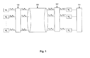
- FIG. 1 shows an arrangement according to the invention for data transmission in the application case with a central switching device 300 and a plurality of terminals M 1 , M 2 ... M n and M 1 ', M 2 ', ... M n ', which are preferably xDSL Modems are.
- the terminals M 1 and M 1 ', M 2 and M 2 ' ... M n and M n ' represent 1 ... n any xDSL connections. They are each via a pair of wires S 1 / E 1 , S 2 / E 2 ...
- the reference symbols S iT , S iK , S ' iT , S' iK , E iT , E iK , E ' iT , E' iK each denote the subscriber or cable-side section the send or receive path on the two cable sides.
- the wire pairs are combined into a bundle 200 of lines and are located in the immediate vicinity of this cable in the area of this cable.
- one, if necessary two, devices 100 and 100 'according to the invention are located in the transmission path between the modems and the wire pairs of the cable.
- the individual wire pairs of the cable bundle 200 are connected to the terminals M 1 ', M 2 ' ... M n 'at their end on the exchange side. At their subscriber end, individual wire pairs are connected to the terminals M 1 , M 2 ... M n .
- These wire pairs can also be combined to form a further basic bundle.
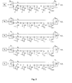
- FIG. 2 shows a first example of a circuit arrangement that can be used in a device according to the invention.
- a plurality of wire pairs, S 1 / E 1 , S 2 / E 2 ... S n / E n which are connected to both the send and the receive signal of the associated modem pair M 1 - M 1 ', M 2 - M 2 '... M n - M n ' are interconnected, are suppressed against each other and against an external source of interference.
- each wire pair of the cable bundle which contributes to interference in the other wire pairs, is inserted into the transmission lines S.
- G K1 , G K2 ... G Kn on the cable side or G T1 , G T2 ...
- each receive line E 1 , E 2 ... E n n are assigned adaptive filters A, where n indicates the number of wire pairs present.
- the adaptive filters receive as a reference signal the signal tapped at the cable-side fork point 1, 2 ... n of an adjacent pair of wires. This is made up of the signal sent and received on this wire pair and the interference signals from the neighboring wire pairs.
- An adaptive filter is thus assigned to two wire pairs in order to suppress the signal transmitted on the first reception line, for example E 1 , against the signal transmitted on a further wire pair, for example S 2 / E 2 .
- Another adaptive filter A x is provided to compensate for an external interference.
- the circuit arrangement according to the invention comprises a matrix of nxn adaptive filters with which all interference influences are mutually compensated. By tapping the reference signal at the fork point of adjacent wires, both the near and the far crosstalk are compensated.
- FIG. 3 shows a further circuit arrangement in which, for example, in order to suppress a received signal on the wire pair S 1 / E 1, two reference points 2a, 2b; ... na, nb and the corresponding number of adaptive filters are used.
- the transmit and receive signals are used separately as reference signals.
- an adaptive filter is also provided for the own pair of wires, which taps as a reference signal the signal sent by the own modem as reference point 1 and thus effects an echo cancellation.
- a further adaptive filter is provided for the compensation of external disturbances.
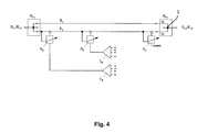
- FIG. 4 shows a further example of a circuit arrangement according to the invention, only one pair of wires and the associated adaptive filters being shown.
- three adaptive filters A S , A E , A X are assigned to each pair of wires.
- a filter A S receives as a reference signal the sum of all transmission signals of all or only the remaining wire pairs summed up in a summing element ⁇ s .
- the second filter A E receives as
- Reference signal is the sum total of all received signals of the other wire pairs in a summing element ⁇ E.
- a filter A X is used to compensate for external interference.
- the reference points 1a, 1b ... na, nb correspond to those from FIG. 3. This arrangement can be implemented simply and inexpensively, since the number of adaptive filters is reduced compared to the examples according to FIGS. 2 and 3.
- FIG. 5 A further simplification is shown in FIG. 5.
- a filter A X again serves to compensate for external disturbances.
- a further simplification results from the fact that the supplier uses an unconnected wire pair for the reference signals. With a suitable position within the cable, all disturbing signals are naturally present on it.
- the summing element can thus be omitted and replaced by an operational amplifier to which the pair of reference wires is connected and which decouples the summing element and makes it available to each transversal filter.
- a filter A X again serves to compensate for external disturbances.
Abstract
Description
Die Erfindung betrifft eine Vorrichtung zur Verbesserung
der Übertragungseigenschaften eines Bündels elektrischer
Datenleitungen gemäss Anspruch 1 sowie eine Anordnung zur
Datenübertragung gemäss Anspruch 11.The invention relates to a device for improvement
the transmission properties of a bundle of electrical
Data lines according to
Bei der Übertragung von Daten über mehrere Datenleitungen, die sich in unmittelbarer räumlicher Nähe zueinander befinden, besteht das Problem des Übersprechens, insbesondere des Nah- und/oder Fernnebensprechens (Near bzw. Far End Cross Talk, NEXT bzw. FEXT). Derartige Probleme treten insbesondere bei der Beschaltung der eigentlich für Niederfrequenzübertragung ausgelegten Kupferkabel im Zugangsbereich eines Telekommunikationsnetzes mit hochbitratigen Übertragungssystemen auf. Hochbitratige Übertragungssysteme wie xDSL (DigitalSubscriber Line, z.B. HDSL, SDSL, ADSL, VDSL) wurden entwickelt, um die vorhandene Infrastruktur aus Kupferdoppeladern in Ortsnetzkabeln und anderen Fernemeldekabeln für die Übertragung hoher Datenströme nutzbar zu machen. Die mehrfache oder gemischte Beschaltung dieser Kabel mit verschiedenen Übertragungstechniken führt häufig zum Problem der spektralen Inkompatibilität. Dabei stören sich mehrere Übertragungseinrichtungen, die an ein gemeinsames Kabel angeschaltet sind, gegenseitig. Die Fernmeldekabel können häufig nicht optimal genutzt werden. Die bei einer vorgegebenen Übertragungsqualität mögliche Übertragungskapazität ist begrenzt. Als Folge dürfen entweder nicht alle Aderpaare beschaltet werden, oder es ergeben sich Einschränkungen in den überbrückbaren Entfernungen.When transferring data over multiple data lines, which are in close spatial proximity to each other there is a problem of crosstalk, especially near and / or distant crosstalk (near or Far End Cross Talk, NEXT or FEXT). such Problems occur particularly when wiring the actually designed for low frequency transmission Copper cable in the access area of a telecommunications network with high bit rate transmission systems. High bit rate transmission systems like xDSL (Digital Subscriber Line, e.g. HDSL, SDSL, ADSL, VDSL) were designed to take advantage of the existing infrastructure Copper pairs in local network cables and others Telecommunication cables for the transmission of high data streams make usable. The multiple or mixed Wiring these cables with different Transmission techniques often lead to the problem of spectral incompatibility. Several interfere Transmission equipment connected to a common cable are turned on, mutually. The communication cables can are often not used optimally. The one predetermined transmission quality possible transmission capacity is limited. As a result, may not either all wire pairs are connected, or it results Limitations in the distances that can be bridged.
Der Einfluss der Störungen kann gering gehalten werden, indem die an das Kabelbündel angeschalteten Endgeräte aufeinander abgestimmt werden, insbesondere synchronisiert werden. Dieses ist jedoch aufwendig und führt zu Einschränkungen bezüglich der verwendeten Modems und Übertragungstechniken.The influence of the disturbances can be kept low, by the devices connected to the cable bundle be coordinated, in particular synchronized become. However, this is complex and leads to Restrictions on the modems used and Transmission technologies.
Aus der US 5,970,088 ist beispielsweise ein Kompensationsverfahren für einen Pool aus N identischen logischen MDSL-Modems bekannt. Es dient zur Kompensation der NEXT Interferenz. Die Sender der Modems sind mit einem Taktgenerator synchronisiert. Die von den N Modems empfangenen Signale werden nach dem Empfang mittels einer Kompensationsschaltung entstört. Die Kompensationsschaltung besteht aus N Untereinheiten, von denen jeweils eine jeweils einem Modem zugeordnet ist. Eine Untereinheit umfasst N adaptive Filter, deren Ausgangssignal zur Korrektur des bereits vom Modem empfangenen und digitalisierten Signals dient. Als Referenzsignal für die adaptiven Filter dient das von jeweils einem der N Modems gesendete Sendesignal. Die Ausgangssignale aller adaptiven Filter einer Untereinheit werden kombiniert und zur Korrektur des bereits empfangenen Empfangssignals verwendet. Das in der US 5,970,088 beschriebene Kompensationsverfahren erfordert N identische Modems und ist daher nicht zum Entstören beliebiger Systeme geeignet. From US 5,970,088, for example Compensation method for a pool of N identical logical MDSL modems known. It is used for compensation the NEXT interference. The transmitters of the modems are with one Clock generator synchronized. The one from the N modems received signals are received by a Compensating circuit suppressed. The compensation circuit consists of N subunits, each of which one is assigned to a modem. A subunit comprises N adaptive filters, the output signal of which Correction of the one already received by the modem digitized signal is used. As a reference signal for the adaptive filter is used by one of the N modems broadcast signal. The output signals of all adaptive Filters of a subunit are combined and used Correction of the received signal already received used. That described in US 5,970,088 Compensation method requires N identical modems and is therefore not suitable for suppressing any system.
Die Übertragungseigenschaften des Kabels selbst bleiben unverändert, und das bereits empfangene Signal wird nachträglich aufbereitet.The transmission properties of the cable itself remain unchanged, and the signal already received will subsequently processed.
Der Erfindung liegt die Aufgabe zugrunde, eine Vorrichtung anzugeben, mit der die Übertragungseigenschaften eines Bündels elektrischer Datenleitungen verbessert wird, sodass unabhängig von den an die Datenleitungen angeschalteten Geräten eine Entstörung der Leitungen untereinander und damit eine Erhöhung der Übertragungskapazität ermöglicht wird.The invention has for its object a device to specify with which the transmission properties of a Bundle of electrical data lines is improved, so regardless of the on the data lines connected devices interference suppression of the lines among themselves and thus an increase in Transmission capacity is made possible.
Die Aufgabe wird gelöst durch eine Vorrichtung zur
Verbesserung der Übertragungseigenschaften eines Bündels
elektrischer Datenleitungen mit den Merkmalen von Anspruch
1. Die Aufgabe wird weiterhin gelöst durch eine Anordnung
zur Datenübertragung mit einer solchen Vorrichtung gemäss
Anspruch 11. Vorteilhafte Weiterbildungen der Erfindung
sind in den abhängigen Ansprüchen, der Beschreibung und
den Zeichnungen angegeben.The object is achieved by a device for
Improve the transmission properties of a bundle
electrical data lines with the features of
Erfindungsgemäss umfasst die Vorrichtung wenigstens ein adaptives Filter, mit dem ein auf einer ersten Leitung übertragenes Signal entstört wird. Indem die Vorrichtung innerhalb der Übertragungsstrecke, z.B. an einem oder beiden Enden des Kabelbündels angeordnet ist, werden die Übertragungseigenschaften des Kabelbündels selbst verbessert. Kenntnisse über die verwendeten Übertragungstechniken bzw. die angeschlossenen Endgeräte sind nicht notwendig. Die Vorrichtung ist vollständig transparent und unabhängig von der Struktur der angeschlossenen Geräte. Den Teilnehmern müssen daher keine Einschränkungen hinsichtlich der verwendeten Geräte und Übertragungstechniken auferlegt werden, um eine hohe Übertragungsleistung bzw. - qualität zu erhalten.According to the invention, the device comprises at least one adaptive filter with which one on a first line transmitted signal is suppressed. By placing the device within the transmission link, e.g. on one or both ends of the cable bundle is arranged, the Transmission properties of the cable bundle itself improved. Knowledge of the transmission techniques used or the connected devices are not necessary. The device is completely transparent and regardless of the structure of the connected devices. The participants therefore have no restrictions regarding of the devices and transmission technologies used be imposed in order to achieve a high transmission capacity or maintain quality.
Adaptive Filter zur Reduzierung bzw. Kompensation einer Störung unbekannter Natur auf einer Signalleitung sind an sich bekannt. Sie sind beispielsweise in B. Widrow und S. Stearns, 'Adaptive Signal Processing', Prentice-Hall, Inc., New Jersey, 1985, beschrieben. Ein auf einer Signalleitung übertragenes zu entstörendes Nutzsignal setzt sich zusammen aus dem ungestörten Signal und dem Störeinfluss der unbekannten Signalquelle. Ein mit dieser Signalquelle korreliertes Signal wird als Referenzsignal einem adaptiven Filter zugeführt. Das Filter erzeugt ein Kompensationssignal, das vom Nutzsignal subtrahiert wird. Das so erhaltene kompensierte Nutzsignal wird dem Filter als Fehlersignal zugeführt. Über einen geeigneten Adaptionsalgorithmus werden die Filterparameter so eingestellt, dass die Leistung des kompensierten Nutzsignals minimiert wird, das somit im Idealfall dem ungestörten Signal entspricht.Adaptive filter to reduce or compensate for a Disruption of unknown nature on a signal line is on known. They are, for example, in B. Widrow and S. Stearns, Adaptive Signal Processing, Prentice-Hall, Inc., New Jersey, 1985. One on one Signal line transmitted useful signal to be suppressed is composed of the undisturbed signal and the Interference from the unknown signal source. One with this Signal source correlated signal is used as a reference signal fed to an adaptive filter. The filter creates a Compensation signal that is subtracted from the useful signal. The compensated useful signal thus obtained is the filter supplied as an error signal. About a suitable one Adaptation algorithm, the filter parameters are like this set that the performance of the compensated Useful signal is minimized, which ideally the corresponds to undisturbed signal.
Die Erfindung kann in einer Vielzahl von Ausführungsformen realisiert werden, von denen einige in den Zeichnungen dargestellt sind. Jeder zu entstörenden Leitung ist wenigstens ein adaptives Filter zugeordnet. Dieses erzeugt ein Kompensationssignal, welches von dem auf der Leitung übertragenen Nutzsignal subtrahiert wird. Als Referenzsignal für das adaptive Filter dient wenigstens ein von einer weiteren Leitung abgegriffenes Signal, so dass der Störeinfluss, z.B. NEXT und/oder FEXT, der auf dieser Leitung übertragenen Signale reduziert wird. In dieser Variante der Erfindung ist für jeweils ein zu entkoppelndes Paar von Leitungen ein adaptives Filter vorgesehen. Es ist auch möglich, die Referenzsignale nur von denjenigen Leitungen, auf denen gesendet wird, abzugreifen.The invention can take a variety of forms can be realized, some of which are in the drawings are shown. Everyone is to be suppressed assigned at least one adaptive filter. This creates a compensation signal which of the on the line transmitted useful signal is subtracted. As Reference signal for the adaptive filter serves at least a signal tapped from another line, see above that the interference, e.g. NEXT and / or FEXT on this line transmitted signals is reduced. In this variant of the invention is for one each decoupling pair of lines an adaptive filter intended. It is also possible to use the reference signals only of the lines on which transmission is carried out tap off.
Um die Anzahl adaptiver Filter zu reduzieren, werden in einer weiteren Variante die von den störenden Leitungen abgegriffenen Signale zu einem gemeinsamen Referenzsignal kombiniert, wobei beispielsweise ihre direkte oder gewichtete Summe gebildet wird. Dieses Referenzsignal wird dann einem gemeinsamen adaptiven Filter zugeführt.To reduce the number of adaptive filters, in a further variant that of the interfering lines tapped signals to a common reference signal combined, for example their direct or weighted sum is formed. This reference signal is then fed to a common adaptive filter.
In einer weiteren vorteilhaften Ausbildungsform, wird das Referenzsignal von einer nicht beschalteten Leitung abgegriffen. Dieses Signal ist eine Abbildung aller Störeinflüsse benachbarter Leitungen, auf denen gesendet oder empfangen wird. Das abgegriffene Signal gibt daher im wesentlichen auch die entsprechenden Störeinflüsse auf die zu entstörende Leitung wieder. Wird es erfindungsgemäss als Referenzsignal für ein adaptives Filter verwendet, gelingt eine schnelle Adaption des Filters und damit eine schnelle Kompensation.In another advantageous form of training, this will be Reference signal from an unwired line tapped. This signal is an illustration of all Interference from neighboring lines on which are sent or is received. The tapped signal is therefore in also the corresponding interference influences on the line to be suppressed again. Will it be according to the invention used as a reference signal for an adaptive filter, a quick adaptation of the filter and thus one succeeds quick compensation.
In einer weiteren bevorzugten Ausführungsform wird ein Referenzsignal ausserhalb des Kabelbündels abgegriffen, beispielsweise an einer externen Antenne. Auf diese Weise können auch externe Störeinflüsse auf einzelne oder alle Datenleitungen kompensiert werden.In a further preferred embodiment, a Tapped off reference signal outside the cable bundle, for example on an external antenna. In this way can also cause external interference to some or all of them Data lines are compensated.
Um die erfindungsgemässe Vorrichtung in die Übertragungsstrecke einzubauen, sind vorzugsweise zwei Anschlüsse vorhanden, wobei der eine beispielsweise zum Anschluss des zu entstörenden Kabelbündels und der andere zum Anschluss eines zu einem oder mehreren Teilnehmern führenden Kabelbündels oder zum direkten Anschluss von Endgeräten, z.B. xDSL-Geräten dient. Die Vorrichtung umfasst des weiteren ein die Anschlüsse verbindendes Bündel aus vorrichtungsinternen Verbindungsleitungen, wobei diese Verbindungsleitungen wenigstens einen Anschlusspunkt aufweisen, über welchen Referenz- und/oder Fehlersignale abgegriffen und/oder Korrektursignale zugeführt werden können. Am externen Kabel selbst müssen daher keine Modifikationen vorgenommen werden.To the device according to the invention in the transmission path to install, preferably two connections available, the one for example to connect the cable bundle to be suppressed and the other one for connection one leading to one or more participants Cable bundle or for the direct connection of end devices, e.g. xDSL devices. The device comprises the another bundle connecting the connections device-internal connecting lines, these Connection lines at least one connection point have which reference and / or error signals tapped and / or correction signals are supplied can. There is therefore no need for the external cable itself Modifications are made.
Zum Entstören von Aderpaaren umfasst die Vorrichtung des weiteren Gabelschaltungen, mit denen die Sende- und Empfangssignale, welche sich gemeinsam auf jedem angeschalteten Aderpaar des Kabelbündels befinden, getrennt und jeweils einer eigenen internen Verbindungsleitung zugeordnet werden. An diesen Verbindungsleitungen können dann an geeigneter Stelle die Referenz- und Fehlersignale zur Einstellung der adaptiven Filter abgegriffen werden und die erzeugten Korrektursignale zugeführt werden. Bei einem Ausfall der adaptiven Filter, z.B. bei einem Stromausfall, wird der Datenfluss nicht unterbrochen.To suppress wire pairs, the device comprises the further hybrid circuits with which the transmit and Receive signals that are common to each connected wire pair of the cable bundle, separately and each with its own internal Connection line can be assigned. On this Connection lines can then the appropriate place Reference and error signals for setting the adaptive Filters are tapped and the generated ones Correction signals are supplied. If the adaptive filter, e.g. in the event of a power failure, the Data flow not interrupted.
Für eine möglichst gute Kompensation wird jede Datenleitung gegenüber jeder weiteren Datenleitung entkoppelt, indem beispielsweise für jede weitere Datenleitung ein adaptives Filter vorgesehen ist oder die von den weiteren Datenleitungen abgegriffenen Signale einem gemeinsamen adaptiven Filter als Referenzsignal zugeführt werden. Da das Übersprechen stark entfernungsabhängig ist, kann es für viele Anwendungen ausreichen, nur die unmittelbar benachbarten Datenleitungen gegeneinander zu entstören. Bei Fernmeldekabeln sind häufig zwei Paare von Kupferdoppeladern miteinander verdrillt. Mehrere solcher Sternvierer sind in einem gemeinsamen Grundbündel enthalten. Wiederum mehrere solcher Grundbündel bilden das Fernmeldekabel. In einem solchen Fall werden vorzugsweise wenigstens die Datenleitungen eines Sternenvierers und besonders bevorzugt auch die eines Grundbündels gegeneinander entstört.Every data line is used for the best possible compensation decoupled from any other data line, for example, for each additional data line adaptive filter is provided or by the others Data lines tapped signals a common adaptive filter can be supplied as a reference signal. There crosstalk is highly dependent on the distance, it can sufficient for many applications, only those immediately to suppress adjacent data lines from each other. Telecommunication cables often have two pairs of Copper twisted pair twisted together. Several such Star quads are in a common basic bundle contain. Again, several such basic bundles form that Telecommunication cables. In such a case, be preferred at least the data lines of a star quad and particularly preferably also that of a basic bundle against one another suppressed.
Zur Einstellung der adaptiven Filter sind eine Vielzahl von Adaptionsmethoden bekannt, die alle die Minimierung des kompensierten Signals (Fehlersignal) anstreben. Beispielsweise können ein Least-Mean-Square (LMS)-Algorithmus, der RLS-Algorithmus (Recursive-Least-Squares-Algorithmus), Self-Recovering-Equalization- bzw. Blind-Equalization-Algorithmen oder ein anderes geeignetes Verfahren verwendet werden. Das Verfahren der Leistungsminimierung hat den Vorteil, dass die erfindungsgemässe Vorrichtung transparent bezüglich der Übertragungsraten, Leitungscodes und anderer Übertragungsparameter ist und keine Trainings- oder Synchronisationsverfahren benötigt werden.There are a variety of settings for adaptive filters known from adaptation methods, all minimizing aim for the compensated signal (error signal). For example can use a least mean square (LMS) algorithm, the RLS algorithm (recursive least squares algorithm), Self-recovering equalization or blind equalization algorithms or another suitable one Procedures are used. The process of minimizing performance has the advantage that the inventive Device transparent with regard to the transmission rates, Line codes and other transmission parameters is and no training or synchronization procedures required become.
Ausführungsbeispiele der Erfindung sind in den Zeichnungen dargestellt und im Folgenden beschrieben. Dabei zeigen rein schematisch:
- Fig. 1
- Die prinzipielle Anordnung zweier erfindungsgemässer Vorrichtungen innerhalb einer Übertragungsstrecke;
- Fig. 2
- ein erstes Beispiel für eine erfindungsgemässe Schaltungsanordnung mit einem Referenzpunkt pro Aderpaar;
- Fig. 3
- ein weiteres Beispiel für eine erfindungsgemässe Schaltungsanordnung mit zwei Referenzpunkten pro Aderpaar;
- Fig. 4
- ein weiteres Beispiel für eine erfindungsgemässe Schaltungsanordnung mit je einem Summierglied für Sende- bzw. Empfangssignale benachbarter Leitungen;
- Fig. 5
- eine weitere erfindungsgemässe Schaltungsanordnung mit einem Summierglied für sämtliche Störsignale.
- Fig. 1
- The basic arrangement of two devices according to the invention within a transmission path;
- Fig. 2
- a first example of a circuit arrangement according to the invention with one reference point per pair of wires;
- Fig. 3
- another example of a circuit arrangement according to the invention with two reference points per wire pair;
- Fig. 4
- another example of a circuit arrangement according to the invention, each with a summing element for transmit and receive signals of adjacent lines;
- Fig. 5
- a further circuit arrangement according to the invention with a summing element for all interference signals.
Fig. 1 zeigt eine erfindungsgemässe Anordnung zur
Datenübertragung im Anwendungsfall mit einer zentralen
Vermittlungseinrichtung 300 und einer Mehrzahl von
Endgeräten M1, M2 ... Mn sowie M1', M2', ... Mn', die
vorzugsweise xDSL-Modems sind. Die Endgeräte M1 und M1', M2
und M2' ... Mn und Mn' stellen 1...n beliebige xDSL-Verbindungen
dar. Sie sind über jeweils ein Aderpaar
S1/E1, S2/E2 ... Sn/En verbunden Die Bezugszeichen SiT, SiK,
S'iT, S'iK, EiT, EiK, E'iT, E'iK bezeichnen jeweils das
teilnehmer- bzw. kabelseitige Teilstück des Sende- bzw.
Empfangswegs auf den beiden Kabelseiten. Die Aderpaare
sind zu einem Bündel 200 von Leitungen zusammengefasst und
befinden sich im Bereich dieses Kabels in unmittelbarer
räumlicher Nähe zueinander. Zur Kompensation ihrer
gegenseitiger Störeinflüsse befinden sich eine, erforderlichenfalls
zwei erfindungsgemässe Vorrichtungen 100 bzw.
100' im Übertragungsweg zwischen den Modems und den
Aderpaaren des Kabels. An ihrem vermittlungsseitigen Ende
sind die einzelnen Aderpaare des Kabelbündels 200 mit den
Endgeräten M1', M2' ... Mn' beschaltet. An ihrem
teilnehmerseitigen Ende sind einzelne Aderpaare mit den
Endgeräten M1, M2 ... Mn beschaltet. Diese Aderpaare können
auch zu einem weiteren Grundbündel zusammengefasst sein.1 shows an arrangement according to the invention for data transmission in the application case with a
Fig. 2 zeigt ein erstes Beispiel für eine
Schaltungsanordnung, die in einer erfindungsgemässen
Vorrichtung verwendet werden kann. Eine Mehrzahl von
Aderpaaren, S1/E1 , S2/E2 ... Sn/En , welche sowohl mit dem
Sende- als auch dem Empfangssignal des zugehörigen
Modempaares M1 - M1', M2 - M2' ... Mn - Mn' beschaltet sind,
werden gegeneinander und gegen eine externe Störungsquelle
entstört. Dazu wird jedes Aderpaar des Kabelbündels,
welches zu Störungen der anderen Aderpaare beiträgt,
mittels hochwirksamer Gabelschaltungen GK1, GK2 ... GKn an
der Kabelseite bzw. GT1, GT2 ... GTn an der Teilnehmerseite
in die Sendeleitungen S1, S2 ... Sn und die
Empfangsleitungen E1, E2 ... En aufgeteilt. Zur Entstörung
der Empfangssignale sind jeder Empfangsleitung E1, E2 ...
En n adaptive Filter A zugeordnet, wobei n die Anzahl der
vorhandenen Aderpaare angibt. Die adaptiven Filter
erhalten als Referenzsignal das am kabelseitigen
Gabelpunkt 1, 2 ... n jeweils eines benachbarten
Aderpaares abgegriffene Signal. Dieses setzt sich zusammen
aus dem auf diesem Aderpaar gesendeten und empfangenen
Signal sowie aus den Störsignalen von den benachbarten
Aderpaaren. Jeweils zwei Aderpaaren ist somit ein
adaptives Filter zugeordnet, um das auf der ersten
Empfangsleitung, z.B. E1, übertragene Signal gegen das auf
einem weiteren Aderpaar, beispielsweise S2/E2, übertragene
Signal zu entstören. Ein weiteres adaptives Filter Ax, ist
zur Kompensation eines externen Störeinflusses vorgesehen.
Die erfindungsgemässe Schaltungsanordnung umfasst
insgesamt eine Matrix aus n x n adaptiven Filtern, mit
denen sämtliche Störeinflüsse wechselseitig kompensiert
werden. Indem das Referenzsignal am Gabelpunkt
benachbarter Adern abgegriffen wird, wird sowohl das Nahals
auch das Fernnebensprechen kompensiert.2 shows a first example of a circuit arrangement that can be used in a device according to the invention. A plurality of wire pairs, S 1 / E 1 , S 2 / E 2 ... S n / E n , which are connected to both the send and the receive signal of the associated modem pair M 1 - M 1 ', M 2 - M 2 '... M n - M n ' are interconnected, are suppressed against each other and against an external source of interference. For this purpose, each wire pair of the cable bundle, which contributes to interference in the other wire pairs, is inserted into the transmission lines S. By means of highly effective hybrid circuits G K1 , G K2 ... G Kn on the cable side or G T1 , G T2 ... G Tn on the subscriber side 1 , S 2 ... S n and the receive lines E 1 , E 2 ... E n divided. To suppress the received signals, each receive line E 1 , E 2 ... E n n are assigned adaptive filters A, where n indicates the number of wire pairs present. The adaptive filters receive as a reference signal the signal tapped at the cable-
Fig. 3 zeigt eine weitere Schaltungsanordnung, bei der
beispielsweise zum Entstören eines Empfangssignals auf dem
Aderpaar S1/E1 pro benachbartem störenden Aderpaar zwei
Referenzpunkte 2a, 2b; ... na, nb und die entsprechende
Anzahl adaptiver Filter verwendet werden. Die Sende- und
Empfangssignale werden separat als Referenzsignale
verwendet. Des weiteren ist auch für das eigene Aderpaar
ein adaptives Filter vorgesehen, welches als
Referenzsignal das vom eigenen Modem gesendete Signal als
Referenzpunkt 1 abgreift und damit eine Echokompensation
bewirkt. Wie bei der Schaltungsanordnung gemäss Fig. 2 ist
ein weiteres adaptives Filter für die Kompensation
externer Störungen vorgesehen.3 shows a further circuit arrangement in which, for example, in order to suppress a received signal on the wire pair S 1 / E 1, two
Fig. 4 zeigt ein weiteres Beispiel einer erfindungsgemässen Schaltungsanordnung, wobei nur ein Aderpaar und die zugeordneten adaptiven Filter dargestellt sind. Jedem Aderpaar sind vorliegend drei adaptive Filter AS, AE, AX, zugeordnet. Ein Filter AS erhält als Referenzsignal die in einem Summierglied Σs aufsummierte Summe sämtlicher Sendesignale von allen oder nur den übrigen Aderpaaren. Das zweite Filter AE erhält als4 shows a further example of a circuit arrangement according to the invention, only one pair of wires and the associated adaptive filters being shown. In the present case, three adaptive filters A S , A E , A X are assigned to each pair of wires. A filter A S receives as a reference signal the sum of all transmission signals of all or only the remaining wire pairs summed up in a summing element Σ s . The second filter A E receives as
Referenzsignal die in einem Summierglied ΣE aufsummierte
Summe sämtlicher Empfangssignale der übrigen Aderpaare.
Ein Filter AX dient zur Kompensation externer Störungen.
Die Referenzpunkte 1a, 1b... na, nb entsprechen denen aus
Fig. 3. Diese Anordnung kann einfach und kostengünstig
realisiert werden, da die Anzahl adaptiver Filter
gegenüber den Beispielen nach Fig. 2 und 3 reduziert ist.Reference signal is the sum total of all received signals of the other wire pairs in a summing element Σ E. A filter A X is used to compensate for external interference. The
Eine weitere Vereinfachung ist in Fig. 5 dargestellt. Hierbei ist lediglich ein adaptives Filter AΣ für sämtliche von benachbarten Aderpaaren abgegriffenen Störsignale vorhanden. Diese werden in einem Summierglied Σ aufsummiert, wobei das Summensignal als Referenzsignal dient. Ein Filter AX dient wieder zur Kompensation externer Störungen.A further simplification is shown in FIG. 5. In this case, there is only one adaptive filter A Σ for all interference signals picked up by adjacent wire pairs. These are summed up in a summing element Σ, the summation signal serving as a reference signal. A filter A X again serves to compensate for external disturbances.
In einer weiteren Vereinfachung der Schaltungsanordnung ist es denkbar, dass die Funktion von AX in AΣ integriert wird, so dass AX entfallen kann.In a further simplification of the circuit arrangement, it is conceivable that the function of A X is integrated in A Σ , so that A X can be omitted.
Eine weitere Vereinfachung ergibt sich dadurch, dass der Lieferant für die Referenzsignale ein nicht beschaltetes Aderpaar verwendet wird. Auf ihm sind bei geeigneter Lage innerhalb des Kabels naturgemäß alle störenden Signale vorhanden. Somit kann das Summierglied entfallen und durch einen Operationsverstärker ersetzt werden, an welchem das Referenzaderpaar angeschlossen ist und welcher das Summierglied entkoppelt jedem Transversalfilter zur Verfügung stellt. Ein Filter AX dient wieder zur Kompensation externer Störungen. A further simplification results from the fact that the supplier uses an unconnected wire pair for the reference signals. With a suitable position within the cable, all disturbing signals are naturally present on it. The summing element can thus be omitted and replaced by an operational amplifier to which the pair of reference wires is connected and which decouples the summing element and makes it available to each transversal filter. A filter A X again serves to compensate for external disturbances.
Weiterhin möglich ist eine Ausbildung der vorgegebenen Lösungsvariante dadurch, dass das Referenzaderpaar und das externe Störsignal an ein Summierglied mit nur noch zwei Eingängen angeschaltet wird. Dadurch kann das adaptive Filter AX entfallen.It is also possible to design the specified solution variant by connecting the pair of reference wires and the external interference signal to a summing element with only two inputs. As a result, the adaptive filter A X can be omitted.
Claims (13)
Priority Applications (18)
| Application Number | Priority Date | Filing Date | Title |
|---|---|---|---|
| EP01116651A EP1276249A1 (en) | 2001-07-13 | 2001-07-13 | Apparatus for improving the transmission characteristics of a bundle of electrical data lines and data transmission system |
| JP2003514714A JP4652683B2 (en) | 2001-07-13 | 2002-07-15 | Apparatus and data transmission arrangement for improving transmission characteristics of electrical data line bundle |
| BR0211136-5A BR0211136A (en) | 2001-07-13 | 2002-07-15 | Device for enhancing the transmission properties of a data line beam and data transmission arrangement |
| CA2452864A CA2452864C (en) | 2001-07-13 | 2002-07-15 | Device for improving the transmission properties of a bundle of electrical data lines and a system for transmitting data |
| PL367691A PL205135B1 (en) | 2001-07-13 | 2002-07-15 | Device for improving the transmission properties of a bundle of electrical data lines and a system for transmitting data |
| EP02754878A EP1415409B1 (en) | 2001-07-13 | 2002-07-15 | Device for improving the transmission properties of a bundle of electrical data lines and a system for transmitting data |
| PCT/EP2002/007783 WO2003009490A2 (en) | 2001-07-13 | 2002-07-15 | Device for improving the transmission properties of a bundle of electrical data lines and a system for transmitting data |
| ES02754878T ES2321169T3 (en) | 2001-07-13 | 2002-07-15 | DEVICE FOR THE IMPROVEMENT OF THE TRANSMISSION PROPERTIES OF AN ELECTRICAL DATA DRIVING BEAM AND DISPOSITION FOR THE TRANSMISSION OF DATA. |
| MXPA04000250A MXPA04000250A (en) | 2001-07-13 | 2002-07-15 | Device for improving the transmission properties of a bundle of electrical data lines and a system for transmitting data. |
| DE50213275T DE50213275D1 (en) | 2001-07-13 | 2002-07-15 | DEVICE FOR IMPROVING THE TRANSMISSION CHARACTERISTICS OF A BUNDLE OF ELECTRICAL DATA LINES AND ARRANGEMENT FOR DATA TRANSMISSION |
| RU2004104344/09A RU2313179C2 (en) | 2001-07-13 | 2002-07-15 | Device for raising throughput capacity of group of electric data-transfer lines; data transfer system |
| US10/483,685 US7656955B2 (en) | 2001-07-13 | 2002-07-15 | Device for improving the transmission properties of a bundle of electrical data lines and a system for transmitting data |
| IL15985102A IL159851A0 (en) | 2001-07-13 | 2002-07-15 | Device for improving the transmission properties of a bundle of electrical data lines and a system for transmitting data |
| CN028180380A CN1555609B (en) | 2001-07-13 | 2002-07-15 | Device for improving the transmission properties of a bundle of electrical data lines and a system for transmitting data |
| AU2002321214A AU2002321214B2 (en) | 2001-07-13 | 2002-07-15 | Device for improving the transmission properties of a bundle of electrical data lines and a system for transmitting data |
| AT02754878T ATE422735T1 (en) | 2001-07-13 | 2002-07-15 | DEVICE FOR IMPROVING THE TRANSMISSION PROPERTIES OF A BUNCH OF ELECTRICAL DATA CABLES AND ARRANGEMENT FOR DATA TRANSMISSION |
| KR1020047000559A KR100895735B1 (en) | 2001-07-13 | 2002-07-15 | Apparatus for improvement of the transmission characteristics of a bundle of electrical data lines, and an arrangement for data transmission |
| IL159851A IL159851A (en) | 2001-07-13 | 2004-01-13 | Device for improving the transmission properties of a bundle of electrical data lines and a system for transmitting data |
Applications Claiming Priority (1)
| Application Number | Priority Date | Filing Date | Title |
|---|---|---|---|
| EP01116651A EP1276249A1 (en) | 2001-07-13 | 2001-07-13 | Apparatus for improving the transmission characteristics of a bundle of electrical data lines and data transmission system |
Publications (1)
| Publication Number | Publication Date |
|---|---|
| EP1276249A1 true EP1276249A1 (en) | 2003-01-15 |
Family
ID=8177990
Family Applications (2)
| Application Number | Title | Priority Date | Filing Date |
|---|---|---|---|
| EP01116651A Withdrawn EP1276249A1 (en) | 2001-07-13 | 2001-07-13 | Apparatus for improving the transmission characteristics of a bundle of electrical data lines and data transmission system |
| EP02754878A Expired - Lifetime EP1415409B1 (en) | 2001-07-13 | 2002-07-15 | Device for improving the transmission properties of a bundle of electrical data lines and a system for transmitting data |
Family Applications After (1)
| Application Number | Title | Priority Date | Filing Date |
|---|---|---|---|
| EP02754878A Expired - Lifetime EP1415409B1 (en) | 2001-07-13 | 2002-07-15 | Device for improving the transmission properties of a bundle of electrical data lines and a system for transmitting data |
Country Status (16)
| Country | Link |
|---|---|
| US (1) | US7656955B2 (en) |
| EP (2) | EP1276249A1 (en) |
| JP (1) | JP4652683B2 (en) |
| KR (1) | KR100895735B1 (en) |
| CN (1) | CN1555609B (en) |
| AT (1) | ATE422735T1 (en) |
| AU (1) | AU2002321214B2 (en) |
| BR (1) | BR0211136A (en) |
| CA (1) | CA2452864C (en) |
| DE (1) | DE50213275D1 (en) |
| ES (1) | ES2321169T3 (en) |
| IL (2) | IL159851A0 (en) |
| MX (1) | MXPA04000250A (en) |
| PL (1) | PL205135B1 (en) |
| RU (1) | RU2313179C2 (en) |
| WO (1) | WO2003009490A2 (en) |
Families Citing this family (12)
| Publication number | Priority date | Publication date | Assignee | Title |
|---|---|---|---|---|
| DE10046901A1 (en) * | 2000-09-21 | 2002-05-02 | Siemens Ag | Method and device for improving the transmission quality in a packet-oriented data transmission network |
| JP4869853B2 (en) * | 2006-10-02 | 2012-02-08 | 日本電気株式会社 | Transmission output control device, multi-carrier transmission system, transmission output control method, and transmission output control program |
| DE102007018585B4 (en) | 2007-04-18 | 2009-02-26 | Broadband United Gmbh | Apparatus and method for detecting and compensating for spurious signals in a communication system |
| EP2169931B1 (en) * | 2008-09-24 | 2017-08-09 | ADTRAN GmbH | Method and device for data processing and communication system comprising such device |
| KR101162003B1 (en) | 2008-10-28 | 2012-07-03 | 후지쯔 가부시끼가이샤 | Wireless base station device using cooperative harq communication method, wireless terminal device, wireless communication system, and wireless communication method |
| US8432955B2 (en) * | 2009-07-10 | 2013-04-30 | Futurewei Technologies, Inc. | Method for robust crosstalk precoder training in channels with impulse noise |
| RU2585659C2 (en) * | 2011-01-14 | 2016-06-10 | Телефонактиеболагет Л М Эрикссон (Пабл) | Limitation of crosstalk between modems |
| JP5664295B2 (en) * | 2011-02-03 | 2015-02-04 | 富士通株式会社 | Communication device and communication device setting method |
| CA2924486C (en) | 2013-09-18 | 2017-10-31 | Huawei Technologies Co., Ltd. | Deactivation method and system in crosstalk scenario |
| RU2579915C2 (en) * | 2014-04-25 | 2016-04-10 | Вячеслав Николаевич Федоров | Method of suppression of cross-talk interferences in multiwire communication lines |
| CN105896197A (en) * | 2016-05-26 | 2016-08-24 | 江苏省东方世纪网络信息有限公司 | Data cable connector |
| CN112332881B (en) * | 2020-10-19 | 2022-04-26 | 深圳市信锐网科技术有限公司 | Enabling circuit and communication device |
Citations (4)
| Publication number | Priority date | Publication date | Assignee | Title |
|---|---|---|---|---|
| US5271037A (en) * | 1990-10-10 | 1993-12-14 | Alcatel N.V. | Line equipment for the compensation of crosstalk |
| WO1997040587A1 (en) * | 1996-04-19 | 1997-10-30 | Amati Communications Corporation | Radio frequency noise canceller |
| US5887032A (en) * | 1996-09-03 | 1999-03-23 | Amati Communications Corp. | Method and apparatus for crosstalk cancellation |
| US5970088A (en) * | 1996-05-09 | 1999-10-19 | Texas Instruments Incorporated | Reverse channel next cancellation for MDSL modem pool |
Family Cites Families (19)
| Publication number | Priority date | Publication date | Assignee | Title |
|---|---|---|---|---|
| LU85402A1 (en) * | 1983-12-01 | 1984-09-11 | Siemens Ag | METHOD AND CIRCUIT ARRANGEMENT FOR COMPENSATING CROSS-SPEED AND O. ECHO SIGNALS |
| BE1005305A3 (en) * | 1991-09-04 | 1993-06-22 | Zuivere Interkommunale Voor Te | METHOD FOR IN AT LEAST a junction box PROVIDED cable network APPLYING AN ADDITIONAL MODULE AND RESPECT TO USE MODULE. |
| KR0150757B1 (en) * | 1995-12-20 | 1998-11-02 | 양승택 | Line driving system complying with transmission medium characteristics |
| US6014412A (en) * | 1996-04-19 | 2000-01-11 | Amati Communications Corporation | Digital radio frequency interference canceller |
| US6055268A (en) * | 1996-05-09 | 2000-04-25 | Texas Instruments Incorporated | Multimode digital modem |
| US5953412A (en) * | 1996-09-04 | 1999-09-14 | Teltrend, Inc. | Method and apparatus for controlling line conditioner equalizer |
| US6160790A (en) * | 1996-12-31 | 2000-12-12 | Paradyne Corporation | Crosstalk canceller system and method |
| US6014371A (en) * | 1997-03-05 | 2000-01-11 | Paradyne Corporation | Echo cancellation system and method for multipoint networks |
| US6052420A (en) * | 1997-05-15 | 2000-04-18 | Northern Telecom Limited | Adaptive multiple sub-band common-mode RFI suppression |
| EP1068676A4 (en) * | 1998-03-09 | 2007-11-28 | Broadcom Corp | Gigabit ethernet transceiver |
| TW440767B (en) * | 1998-06-02 | 2001-06-16 | Fujitsu Ltd | Method of and apparatus for correctly transmitting signals at high speed without waveform distortion |
| KR100468830B1 (en) * | 1998-06-18 | 2005-05-17 | 삼성전자주식회사 | Receiver and narrowband noise elimination method with narrowband noise cancellation in ultrafast digital subscriber beam system |
| KR100309101B1 (en) * | 1998-08-26 | 2001-11-17 | 윤종용 | Apparatus and method for optimizing hybrid balance and characteristic impedance |
| KR20010019438A (en) * | 1999-08-27 | 2001-03-15 | 윤종용 | Adaptive echo cancel apparatus with programmable analog filter |
| US6965657B1 (en) * | 1999-12-01 | 2005-11-15 | Velocity Communication, Inc. | Method and apparatus for interference cancellation in shared communication mediums |
| DE69915082D1 (en) * | 1999-12-14 | 2004-04-01 | St Microelectronics Nv | DSL transmission system with remote crosstalk compensation |
| EP1109329B1 (en) * | 1999-12-14 | 2003-04-02 | STMicroelectronics S.A. | DSL transmission system with far-end crosstalk cancellation |
| US20020093908A1 (en) * | 2000-11-24 | 2002-07-18 | Esion Networks Inc. | Noise/interference suppression system |
| US6831900B2 (en) * | 2001-02-09 | 2004-12-14 | Agere Systems Inc. | Filter cell, method of deriving an echo component and an echo canceling system employing the same |
-
2001
- 2001-07-13 EP EP01116651A patent/EP1276249A1/en not_active Withdrawn
-
2002
- 2002-07-15 AT AT02754878T patent/ATE422735T1/en not_active IP Right Cessation
- 2002-07-15 RU RU2004104344/09A patent/RU2313179C2/en not_active IP Right Cessation
- 2002-07-15 PL PL367691A patent/PL205135B1/en not_active IP Right Cessation
- 2002-07-15 MX MXPA04000250A patent/MXPA04000250A/en active IP Right Grant
- 2002-07-15 IL IL15985102A patent/IL159851A0/en unknown
- 2002-07-15 US US10/483,685 patent/US7656955B2/en not_active Expired - Fee Related
- 2002-07-15 ES ES02754878T patent/ES2321169T3/en not_active Expired - Lifetime
- 2002-07-15 CN CN028180380A patent/CN1555609B/en not_active Expired - Fee Related
- 2002-07-15 BR BR0211136-5A patent/BR0211136A/en not_active IP Right Cessation
- 2002-07-15 EP EP02754878A patent/EP1415409B1/en not_active Expired - Lifetime
- 2002-07-15 AU AU2002321214A patent/AU2002321214B2/en not_active Ceased
- 2002-07-15 CA CA2452864A patent/CA2452864C/en not_active Expired - Fee Related
- 2002-07-15 DE DE50213275T patent/DE50213275D1/en not_active Expired - Lifetime
- 2002-07-15 KR KR1020047000559A patent/KR100895735B1/en not_active IP Right Cessation
- 2002-07-15 WO PCT/EP2002/007783 patent/WO2003009490A2/en active Application Filing
- 2002-07-15 JP JP2003514714A patent/JP4652683B2/en not_active Expired - Fee Related
-
2004
- 2004-01-13 IL IL159851A patent/IL159851A/en not_active IP Right Cessation
Patent Citations (4)
| Publication number | Priority date | Publication date | Assignee | Title |
|---|---|---|---|---|
| US5271037A (en) * | 1990-10-10 | 1993-12-14 | Alcatel N.V. | Line equipment for the compensation of crosstalk |
| WO1997040587A1 (en) * | 1996-04-19 | 1997-10-30 | Amati Communications Corporation | Radio frequency noise canceller |
| US5970088A (en) * | 1996-05-09 | 1999-10-19 | Texas Instruments Incorporated | Reverse channel next cancellation for MDSL modem pool |
| US5887032A (en) * | 1996-09-03 | 1999-03-23 | Amati Communications Corp. | Method and apparatus for crosstalk cancellation |
Also Published As
| Publication number | Publication date |
|---|---|
| CN1555609B (en) | 2012-04-18 |
| PL367691A1 (en) | 2005-03-07 |
| RU2004104344A (en) | 2005-06-27 |
| PL205135B1 (en) | 2010-03-31 |
| CA2452864A1 (en) | 2003-01-30 |
| ATE422735T1 (en) | 2009-02-15 |
| BR0211136A (en) | 2004-12-14 |
| RU2313179C2 (en) | 2007-12-20 |
| US20040233999A1 (en) | 2004-11-25 |
| EP1415409B1 (en) | 2009-02-11 |
| IL159851A0 (en) | 2004-06-20 |
| JP4652683B2 (en) | 2011-03-16 |
| IL159851A (en) | 2010-06-16 |
| KR20040032856A (en) | 2004-04-17 |
| WO2003009490A2 (en) | 2003-01-30 |
| JP2005521272A (en) | 2005-07-14 |
| US7656955B2 (en) | 2010-02-02 |
| DE50213275D1 (en) | 2009-03-26 |
| ES2321169T3 (en) | 2009-06-03 |
| AU2002321214B2 (en) | 2007-10-04 |
| MXPA04000250A (en) | 2005-09-08 |
| CA2452864C (en) | 2013-05-28 |
| KR100895735B1 (en) | 2009-04-30 |
| CN1555609A (en) | 2004-12-15 |
| EP1415409A2 (en) | 2004-05-06 |
| AU2002321214A2 (en) | 2003-03-03 |
| WO2003009490A3 (en) | 2003-09-25 |
Similar Documents
| Publication | Publication Date | Title |
|---|---|---|
| EP0480323B1 (en) | Line arrangement for compensating cross-talk | |
| DE69530864T2 (en) | Coupling device for connecting a symmetrical signal line to an asymmetrical signal line | |
| DE69922416T2 (en) | METHOD AND DEVICE THE COUPLING OF ANALOG PARTICULAR LINES IN A HOME NETWORK | |
| EP1415409B1 (en) | Device for improving the transmission properties of a bundle of electrical data lines and a system for transmitting data | |
| WO2000019767A2 (en) | Line terminator unit for a subscriber line | |
| DE4329519C2 (en) | Duplex communication coupling system | |
| DE102006045901A1 (en) | A method of transmitting a digital broadcast signal, data communications transmitter, data communications receiver, and data communications system | |
| EP0814574A2 (en) | Circuitry for far end crosstalk compensation | |
| DE69815104T2 (en) | VDSL MODEM DIVIDED INTO A DIGITAL AND ANALOGUE PART | |
| DE102006034835B4 (en) | Device and method for processing a signal | |
| DE102004002694B4 (en) | Phone Line Card | |
| EP1381243A1 (en) | Distributor system of a telecommunication installation | |
| DE10247208A1 (en) | Bridge-circuit arrangement for echo suppression in communication devices e.g. for xDSL-transmission systems, includes variable simulating device for simulating at least one circuit section of bridge branch | |
| DE10324373A1 (en) | Power supply via data lines in local networks | |
| EP0663786B1 (en) | Method of digital data transmission | |
| DE4032068A1 (en) | CIRCUIT ARRANGEMENT FOR COMPENSATING IMPULSE MALFUNCTIONS | |
| DE641097C (en) | Process to reduce the induction interference between the parallel lines in broadcast distribution systems | |
| DE202007014702U1 (en) | Distribution device of a telecommunications system and plug for a distribution device of a telecommunications system | |
| DE10234479A1 (en) | Transmission system for an ISDN subscriber line has a source of signals with an internal resistor and an end resistor to reduce frequency-dependent signal attenuation | |
| DE102018003564A1 (en) | Device for common mode termination | |
| DE102004025425A1 (en) | Circuit for reducing interference signals on the balanced subscriber line by crosstalk | |
| WO2004107643A1 (en) | Local integrated data and telephone network comprising phantom circuits | |
| DE20320599U1 (en) | Local integrated data, telephone network has function networks that selectively transmit a.c. signals between user-side data connections and installation side connections in phantom technology | |
| DE19740303A1 (en) | Telecommunication network e.g. for telephone | |
| DE4236810A1 (en) | Interface for connecting data terminal to token-ring or bus local area network - connects data input=output unit of terminal unit to input of connection module contg. interface, which outputs to plug connector for data signal and impedance matching |
Legal Events
| Date | Code | Title | Description |
|---|---|---|---|
| PUAI | Public reference made under article 153(3) epc to a published international application that has entered the european phase |
Free format text: ORIGINAL CODE: 0009012 |
|
| AK | Designated contracting states |
Kind code of ref document: A1 Designated state(s): AT BE CH CY DE DK ES FI FR GB GR IE IT LI LU MC NL PT SE TR |
|
| AX | Request for extension of the european patent |
Free format text: AL;LT;LV;MK;RO;SI |
|
| AKX | Designation fees paid | ||
| REG | Reference to a national code |
Ref country code: DE Ref legal event code: 8566 |
|
| STAA | Information on the status of an ep patent application or granted ep patent |
Free format text: STATUS: THE APPLICATION IS DEEMED TO BE WITHDRAWN |
|
| 18D | Application deemed to be withdrawn |
Effective date: 20030716 |