EP1276194A1 - Installationskanal mit Kabelrückhalteklammer - Google Patents
Installationskanal mit Kabelrückhalteklammer Download PDFInfo
- Publication number
- EP1276194A1 EP1276194A1 EP02014150A EP02014150A EP1276194A1 EP 1276194 A1 EP1276194 A1 EP 1276194A1 EP 02014150 A EP02014150 A EP 02014150A EP 02014150 A EP02014150 A EP 02014150A EP 1276194 A1 EP1276194 A1 EP 1276194A1
- Authority
- EP
- European Patent Office
- Prior art keywords
- cable retaining
- tongue
- installation channel
- channel
- retaining clips
- Prior art date
- Legal status (The legal status is an assumption and is not a legal conclusion. Google has not performed a legal analysis and makes no representation as to the accuracy of the status listed.)
- Granted
Links
- 238000009434 installation Methods 0.000 title claims description 26
- 230000014759 maintenance of location Effects 0.000 claims abstract 2
- 210000002105 tongue Anatomy 0.000 claims description 28
- 230000003287 optical effect Effects 0.000 claims description 2
- 230000015572 biosynthetic process Effects 0.000 abstract 1
- 238000005755 formation reaction Methods 0.000 abstract 1
- 239000002184 metal Substances 0.000 description 2
- 230000005540 biological transmission Effects 0.000 description 1
- 238000000576 coating method Methods 0.000 description 1
- 238000010616 electrical installation Methods 0.000 description 1
- 238000011900 installation process Methods 0.000 description 1
- 239000003973 paint Substances 0.000 description 1
- 238000010422 painting Methods 0.000 description 1
- 230000000087 stabilizing effect Effects 0.000 description 1
Images


Classifications
-
- H—ELECTRICITY
- H02—GENERATION; CONVERSION OR DISTRIBUTION OF ELECTRIC POWER
- H02G—INSTALLATION OF ELECTRIC CABLES OR LINES, OR OF COMBINED OPTICAL AND ELECTRIC CABLES OR LINES
- H02G3/00—Installations of electric cables or lines or protective tubing therefor in or on buildings, equivalent structures or vehicles
- H02G3/02—Details
- H02G3/04—Protective tubing or conduits, e.g. cable ladders or cable troughs
- H02G3/0406—Details thereof
- H02G3/0418—Covers or lids; Their fastenings
Definitions
- the invention relates to a cable retaining clip for use in installation channels, the an approximately U-shaped body for receiving lines for transmission of electric current, optical signals and / or the like and by a Lid closable, the retaining clips with the channel open Prevent the pipes from escaping.
- retaining clips serve for metal ducts for equipotential bonding between the trunking base and cover and for stabilizing the side parts of the trunking base.
- U1 is a wall channel for receiving electrical installation equipment known, the one-sided open metallic lower part, the opening limiting the Longitudinal sides are provided with outwardly facing grooves, and a plate-shaped, Having the opening of the lower part covering metallic cover.
- the gutters are arranged metallic clamps, each of which on the one hand on associated approach of the cover and on the other hand with at least one as a cutting edge trained contact tip rests against the gutter of the lower part.
- the clip has an im essential U-shaped cross-section. On one of the legs lateral lugs are provided which are provided with lower and upper tips. On the other leg is one Arranged contact tip, which protrudes approximately vertically and the tip formed as a cutting edge is.
- the distance of the upper and lower tips is chosen such that the clip between clamped the walls of the approach and thus held on the cover.
- the tips penetrate the walls and thus form a secure hold as well as a secure electrical connection between cover and bracket on the one hand and on the other hand between clamp and base.
- the invention therefore has the task of an installation channel with cable retaining clips specify the genus mentioned, wherein the cable retaining clips are designed so that the disadvantages described above are eliminated and even with strong Occupancy of the installation channel at any time in a simple manner a re-allocation is possible.
- the mounted cable retaining clip should, if necessary, in the desired Be displaced position and a stepping out of the inserted into the installation channel Prevent cables.
- it should be ensured that they are closed Lid can not move. It should be as easily as possible to later to be able to insert after cable.
- the cable retaining clip the occupied installation channel sufficient Give stiffness so that the lid snapped with sufficient clamping force can be.
- the object is achieved in that in the installation channel the Side walls of the U-shaped body provided with inwardly directed Umkragonne are with the cable retaining clips arranged with their at the end regions Tongues embrace the overhangs of the side walls.
- the cable retaining clip consists of two-sided arranged on a web tongue-shaped Areas.
- the tongue-shaped areas can be designed on the one hand so that the lower middle tongue engages the overhangs of the side walls, come to the other the upper outer tongues on the overhang lie to lie.
- Between middle and outside Tongue is cut each one arranged at the end tapered another tongue. This is bent up so that the tips when putting the lid in this cut and cause a secure contact.
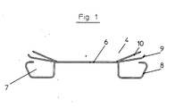
- the cable retaining clip 4 - Fig. 1 - consists of a web portion 6, on at both Side each tongue-shaped portions 7 are arranged. These consist of one centrally disposed lower tongue 8, the inwardly directed projections 3 of the Understand side walls 2.
- the lower tongues 8 are designed so that they with their end portions inside are rolled, these end portions in the installed state in the end of the engage inward Umkragitch 3.
- the upper tongues 9 lie on the Collar 3 on.
- each contact tip 10 arranged such that they project beyond the upper tongues 9. Between the lower tongue 8, contact tip 10 and upper tongue 9 are each free cuts 11 (Fig. 2).
- the installation channel - Fig. 3 - consists essentially of a U-shaped metallic channel lower part 1, on the side walls 2 inwardly directed overhangs 3 are arranged.
- the cable retaining clips 4 are inserted. These consist of on a web 6 on both sides arranged tongue-shaped areas.
- the tongue-shaped regions 7 each have a lower tongue 8 and two upper tongues 9.
- the tongues 8 and 9 surround the projections 3 of the side walls 2 of the channel bottom part first
- the cover to be placed on the lower channel part 1 has an approximately C-shaped cross-section.
- the end regions of the lid correspond to the end regions of the side walls 2 of the channel lower part 1.
- a latching with the channel lower part 1 takes place when the lid is put on.
- the upward contact tips 10 intersect when placing the lid in this and also penetrate layers of paint or coatings of different layer thicknesses. It is thus ensured a reliable electrical connection (equipotential bonding).
- the cable retaining clip 4 is hung on one side after the cover has been removed (FIG. 3).
- the nachinstall Schlude line 12 can be inserted and must not be threaded through.
- the cable retaining clip 4 is designed so that it also holds in the installation channel when it engages on one side in the installation channel and also can be bent so far outward that the nachinstall Schlden lines 12 can be inserted.
- the cable retaining brackets 4 provide the already inserted lines 5 still so much support in the installation channel that they can not fall out. After this installation process, the cable retaining clip is easily locked by moving on the open side again, so that the side walls 2 are stabilized again and with the placement of the cover and the equipotential bonding is restored.
Landscapes
- Engineering & Computer Science (AREA)
- Architecture (AREA)
- Civil Engineering (AREA)
- Structural Engineering (AREA)
- Installation Of Indoor Wiring (AREA)
- Multi-Conductor Connections (AREA)
- Near-Field Transmission Systems (AREA)
- Cable Accessories (AREA)
- Light Guides In General And Applications Therefor (AREA)
Abstract
Description
- Figur 1
- Kabelrückhalteklammer
- Figur 2
- Draufsicht der Kabelrückhalteklammer
- Figur 3
- Ausschnitt aus dem erfindungsgemäßen Installationskanal
Nach der Montage des Installationskanals an einer Wand, werden in diesen Leitungen bzw. Leitungsbündel 5 eingebracht. Um ein Heraustreten der Leitungen bzw. Leitungsbündel 5 zu verhindern, werden die Kabelrückhalteklammern 4 eingesetzt. Diese bestehen aus an einem Steg 6 beidseitig angeordneten zungenförmigen Bereichen. Die zungenförmigen Bereiche 7 weisen je eine untere Zunge 8 und zwei obere Zungen 9 auf. Beim Einsetzen der Kabelrückhalteklammern 4 umgreifen die Zungen 8 und 9 die Umkragungen 3 der Seitenwände 2 des Kanalunterteils 1.
Der auf das Kanalunterteil 1 aufzusetzende Deckel weist einen annähernd C-förmigen Querschnitt auf. Die Endbereiche des Deckels korrespondieren mit den Endbereichen der Seitenwände 2 des Kanalunterteils 1. Dadurch erfolgt beim Aufsetzen des Deckels eine Verrastung mit dem Kanalunterteil 1.
Die nach oben gerichteten Kontaktspitzen 10 schneiden sich beim Aufsetzen des Deckels in diesen ein und durchdringen auch Farbschichten oder Lackierungen unterschiedlicher Schichtdicken. Es wird somit eine zuverlässige elektrische Verbindung (Potentialausgleich) gewährleistet.
Bei einer Nachbelegung des Installationskanals wird nach dem Entfernen des Deckels die Kabelrückhalteklammer 4 einseitig ausgehängt (Fig. 3). Die nachzuinstallierende Leitung 12 kann eingelegt werden und muss nicht mehr durchgefädelt werden. Die Kabelrückhalteklammer 4 ist so ausgeführt, dass sie auch dann im Installationskanal hält, wenn sie einseitig im Installationskanal eingreift und zudem noch soweit nach außen gebogen werden kann, dass die nachzuinstallierenden Leitungen 12 eingelegt werden können.
Nach diesem Verlegevorgang ist die Kabelrückhalteklammer durch Verschieben wieder problemlos auf der offenen Seite zu verrasten, so dass die Seitenwände 2 wieder Stabilisiert werden und mit dem Aufsetzen des Deckels auch der Potentialausgleich wieder gegeben ist.
- 1 -
- Kanalunterteil
- 2 -
- Seitenwände
- 3 -
- Umkragung
- 4 -
- Kabelrückhalteklammer
- 5 -
- Leitungen
- 6 -
- Steg
- 7 -
- zungenförmige Bereiche
- 8 -
- untere Zunge
- 9 -
- obere Zungen
- 10 -
- Kontaktspitzen
- 11 -
- Freischnitte
- 12 -
- nachzuinstallierende Leitung
Claims (5)
- Installationskanal mit Kabelrückhalteklammer, die für den Einsatz in Installationskanälen, die einen annähernd U-förmigen Grundkörper zur Aufnahme von Leitungen zur Übertragung von elektrischem Strom, optischen Signalen und/oder dergleichen aufweisen und durch einen Deckel verschließbar sind, wobei die Kabelrückhalteklammern bei geöffnetem Kanal ein Heraustreten der Leitungen verhindern,
dadurch gekennzeichnet, dass die Kabelrückhalteklammer (4) aus einem Stegbereich (6), an den an beiden Seiten zungenförmigen Bereiche (7) angeordnet sind, wobei diese aus einer mittig angeordneten unteren Zunge (8) und jeweils zwei im Abstand zu dieser angeordneten oberen Zungen (9) besteht und zwischen diesen jeweils nach oben gerichtete Kontaktspitzen (10) angeordnet sind. - Installationskanal mit Kabelrückhalteklammern nach Anspruch 1, dadurch gekennzeichnet, dass die unteren Zungen (8) derart ausgebildet sind, dass sie in ihren Endbereichen eingerollt ausgeführt sind und diese in die Endbereiche der nach innen gerichteten Umkragungen (3) eingreifen.
- Installationskanal mit Kabelrückhalteklammern nach Anspruch 1 und 2 dadurch gekennzeichnet, dass zwischen der unteren Zunge (8) und den oberen Zungen (9) jeweils Kontaktspitzen (10) derart angeordnet sind, dass diese die oberen Zungen (9) überragen.
- Installationskanal mit Kabelrückhalteklammern nach Anspruch 1 bis 3, dadurch gekennzeichnet, dass zwischen unterer Zunge (8), Kontaktspitze (10) sowie oberer Zunge (9) jeweils Freischnitte (11) angeordnet sind.
- Installationskanal mit Kabelrückhalteklammern nach Anspruch 1 bis 4, die untere Zunge (8) und die oberen Zungen (9) jeweils die nach innen gerichteten Umkragungen (3) der Seitenwände (2) des Kanalunterteils (1) umgreifen.
Applications Claiming Priority (2)
| Application Number | Priority Date | Filing Date | Title |
|---|---|---|---|
| DE20110987U | 2001-07-03 | ||
| DE20110987U DE20110987U1 (de) | 2001-07-03 | 2001-07-03 | Installationskanal mit Kabelrückhalteklammer |
Publications (2)
| Publication Number | Publication Date |
|---|---|
| EP1276194A1 true EP1276194A1 (de) | 2003-01-15 |
| EP1276194B1 EP1276194B1 (de) | 2008-08-27 |
Family
ID=7958846
Family Applications (1)
| Application Number | Title | Priority Date | Filing Date |
|---|---|---|---|
| EP02014150A Expired - Lifetime EP1276194B1 (de) | 2001-07-03 | 2002-06-25 | Installationskanal mit Kabelrückhalteklammer |
Country Status (3)
| Country | Link |
|---|---|
| EP (1) | EP1276194B1 (de) |
| AT (1) | ATE406678T1 (de) |
| DE (2) | DE20110987U1 (de) |
Families Citing this family (1)
| Publication number | Priority date | Publication date | Assignee | Title |
|---|---|---|---|---|
| DE20206020U1 (de) | 2002-04-11 | 2002-06-27 | Albert Ackermann GmbH & Co. KG, 51643 Gummersbach | Führungskanal für flexible Leitungen |
Citations (2)
| Publication number | Priority date | Publication date | Assignee | Title |
|---|---|---|---|---|
| DE8704502U1 (de) * | 1987-03-26 | 1987-05-27 | Albert Ackermann GmbH & Co KG, 5270 Gummersbach | Wandkanal zur Aufnahme von elektrischen Installationseinrichtungen |
| EP0743732A1 (de) * | 1995-05-19 | 1996-11-20 | REHAU AG + Co | Einrichtung zum Potentialausgleich |
Family Cites Families (1)
| Publication number | Priority date | Publication date | Assignee | Title |
|---|---|---|---|---|
| DE4103707C2 (de) | 1991-02-07 | 1999-02-04 | Kleinhuis Hermann Gmbh | Kabelkanal, wie Installations- oder Geräteeinbaukanal |
-
2001
- 2001-07-03 DE DE20110987U patent/DE20110987U1/de not_active Expired - Lifetime
-
2002
- 2002-06-25 DE DE50212697T patent/DE50212697D1/de not_active Expired - Lifetime
- 2002-06-25 EP EP02014150A patent/EP1276194B1/de not_active Expired - Lifetime
- 2002-06-25 AT AT02014150T patent/ATE406678T1/de not_active IP Right Cessation
Patent Citations (2)
| Publication number | Priority date | Publication date | Assignee | Title |
|---|---|---|---|---|
| DE8704502U1 (de) * | 1987-03-26 | 1987-05-27 | Albert Ackermann GmbH & Co KG, 5270 Gummersbach | Wandkanal zur Aufnahme von elektrischen Installationseinrichtungen |
| EP0743732A1 (de) * | 1995-05-19 | 1996-11-20 | REHAU AG + Co | Einrichtung zum Potentialausgleich |
Also Published As
| Publication number | Publication date |
|---|---|
| DE20110987U1 (de) | 2001-09-13 |
| DE50212697D1 (de) | 2008-10-09 |
| EP1276194B1 (de) | 2008-08-27 |
| ATE406678T1 (de) | 2008-09-15 |
Similar Documents
| Publication | Publication Date | Title |
|---|---|---|
| DE3503293C2 (de) | ||
| EP0491252A1 (de) | Drahtführungselement für eine Verteilereinheit in Telekommunikationsanlagen | |
| DE3430756C2 (de) | ||
| DE102009005370A1 (de) | Elektrisches Verteilergehäuse für Kraftfahrzeuge | |
| DE3113679A1 (de) | Installationsgeraetedose zum einbau in installationskanaele | |
| AT406991B (de) | Anschlussdose für ein datennetz | |
| EP0248160B1 (de) | Halter für stromführende Sammelschienen | |
| DE102019101180B4 (de) | Halter | |
| DE102016124609A1 (de) | Verteilerkasten zum Einbau in eine Wandöffnung | |
| DE202010010424U1 (de) | Wanddurchführungsklemme für elektrische Leiter | |
| EP1276194B1 (de) | Installationskanal mit Kabelrückhalteklammer | |
| EP0491245B1 (de) | Trägereinheit für Anschlussleisten eines Verteilers in Telekommunikationsanlagen | |
| EP1359650B1 (de) | Anschlussvorrichtung für elektrische Verteiler | |
| EP2525459B1 (de) | Befestigung für Geräteträger | |
| DE19737893B4 (de) | Installationskanal mit Abdeckung und Potentialausgleichsklammer für den Potentialausgleich zwischen diesen | |
| DE2804419A1 (de) | Installationskanal | |
| DE29817565U1 (de) | Geräteaufnahme für eine Unterflurgerätedose | |
| EP1257009B1 (de) | Zugentlastung für einen 1-poligen Steckverbinder mit einem Flachkontakt sowie Steckverbinder damit | |
| DE9113317U1 (de) | Anschlußdose für elektrische Leiter von Kabeln und/oder Schnüren der Telekommunikationstechnik | |
| EP2028738B1 (de) | Überbrückungsklammer zur sicherung von kabeln und leitungen in kabelführungskanälen | |
| DE20022099U1 (de) | Installationskanal mit Kabelhalteklammer | |
| DE102007044508A1 (de) | Kabelverbund | |
| DE29500258U1 (de) | Halter für Kabel oder Rohre mit einer Abdeckleiste | |
| EP1401072B1 (de) | Leitungsführungskanal | |
| CH600637A5 (en) | Electric cable bundle tie |
Legal Events
| Date | Code | Title | Description |
|---|---|---|---|
| PUAI | Public reference made under article 153(3) epc to a published international application that has entered the european phase |
Free format text: ORIGINAL CODE: 0009012 |
|
| AK | Designated contracting states |
Kind code of ref document: A1 Designated state(s): AT BE CH CY DE DK ES FI FR GB GR IE IT LI LU MC NL PT SE TR |
|
| AX | Request for extension of the european patent |
Free format text: AL;LT;LV;MK;RO;SI |
|
| 17P | Request for examination filed |
Effective date: 20030415 |
|
| AKX | Designation fees paid |
Designated state(s): AT BE CH CY DE DK ES FI FR GB GR IE IT LI LU MC NL PT SE TR |
|
| GRAP | Despatch of communication of intention to grant a patent |
Free format text: ORIGINAL CODE: EPIDOSNIGR1 |
|
| GRAS | Grant fee paid |
Free format text: ORIGINAL CODE: EPIDOSNIGR3 |
|
| GRAA | (expected) grant |
Free format text: ORIGINAL CODE: 0009210 |
|
| AK | Designated contracting states |
Kind code of ref document: B1 Designated state(s): AT BE CH CY DE DK ES FI FR GB GR IE IT LI LU MC NL PT SE TR |
|
| REG | Reference to a national code |
Ref country code: GB Ref legal event code: FG4D Free format text: NOT ENGLISH |
|
| REG | Reference to a national code |
Ref country code: CH Ref legal event code: EP |
|
| REG | Reference to a national code |
Ref country code: IE Ref legal event code: FG4D Free format text: LANGUAGE OF EP DOCUMENT: GERMAN |
|
| REF | Corresponds to: |
Ref document number: 50212697 Country of ref document: DE Date of ref document: 20081009 Kind code of ref document: P |
|
| PG25 | Lapsed in a contracting state [announced via postgrant information from national office to epo] |
Ref country code: ES Free format text: LAPSE BECAUSE OF FAILURE TO SUBMIT A TRANSLATION OF THE DESCRIPTION OR TO PAY THE FEE WITHIN THE PRESCRIBED TIME-LIMIT Effective date: 20081208 |
|
| PG25 | Lapsed in a contracting state [announced via postgrant information from national office to epo] |
Ref country code: FI Free format text: LAPSE BECAUSE OF FAILURE TO SUBMIT A TRANSLATION OF THE DESCRIPTION OR TO PAY THE FEE WITHIN THE PRESCRIBED TIME-LIMIT Effective date: 20080827 |
|
| REG | Reference to a national code |
Ref country code: IE Ref legal event code: FD4D |
|
| PG25 | Lapsed in a contracting state [announced via postgrant information from national office to epo] |
Ref country code: DK Free format text: LAPSE BECAUSE OF FAILURE TO SUBMIT A TRANSLATION OF THE DESCRIPTION OR TO PAY THE FEE WITHIN THE PRESCRIBED TIME-LIMIT Effective date: 20080827 Ref country code: IE Free format text: LAPSE BECAUSE OF FAILURE TO SUBMIT A TRANSLATION OF THE DESCRIPTION OR TO PAY THE FEE WITHIN THE PRESCRIBED TIME-LIMIT Effective date: 20080827 |
|
| PG25 | Lapsed in a contracting state [announced via postgrant information from national office to epo] |
Ref country code: PT Free format text: LAPSE BECAUSE OF FAILURE TO SUBMIT A TRANSLATION OF THE DESCRIPTION OR TO PAY THE FEE WITHIN THE PRESCRIBED TIME-LIMIT Effective date: 20090127 |
|
| PLBE | No opposition filed within time limit |
Free format text: ORIGINAL CODE: 0009261 |
|
| STAA | Information on the status of an ep patent application or granted ep patent |
Free format text: STATUS: NO OPPOSITION FILED WITHIN TIME LIMIT |
|
| 26N | No opposition filed |
Effective date: 20090528 |
|
| PG25 | Lapsed in a contracting state [announced via postgrant information from national office to epo] |
Ref country code: IT Free format text: LAPSE BECAUSE OF FAILURE TO SUBMIT A TRANSLATION OF THE DESCRIPTION OR TO PAY THE FEE WITHIN THE PRESCRIBED TIME-LIMIT Effective date: 20080827 |
|
| BERE | Be: lapsed |
Owner name: REHAU A.G. + CO Effective date: 20090630 |
|
| PG25 | Lapsed in a contracting state [announced via postgrant information from national office to epo] |
Ref country code: MC Free format text: LAPSE BECAUSE OF NON-PAYMENT OF DUE FEES Effective date: 20090630 Ref country code: SE Free format text: LAPSE BECAUSE OF FAILURE TO SUBMIT A TRANSLATION OF THE DESCRIPTION OR TO PAY THE FEE WITHIN THE PRESCRIBED TIME-LIMIT Effective date: 20081127 |
|
| REG | Reference to a national code |
Ref country code: CH Ref legal event code: PL |
|
| GBPC | Gb: european patent ceased through non-payment of renewal fee |
Effective date: 20090625 |
|
| REG | Reference to a national code |
Ref country code: FR Ref legal event code: ST Effective date: 20100226 |
|
| PG25 | Lapsed in a contracting state [announced via postgrant information from national office to epo] |
Ref country code: LI Free format text: LAPSE BECAUSE OF NON-PAYMENT OF DUE FEES Effective date: 20090630 Ref country code: CH Free format text: LAPSE BECAUSE OF NON-PAYMENT OF DUE FEES Effective date: 20090630 Ref country code: FR Free format text: LAPSE BECAUSE OF NON-PAYMENT OF DUE FEES Effective date: 20090630 |
|
| PG25 | Lapsed in a contracting state [announced via postgrant information from national office to epo] |
Ref country code: GB Free format text: LAPSE BECAUSE OF NON-PAYMENT OF DUE FEES Effective date: 20090625 |
|
| PG25 | Lapsed in a contracting state [announced via postgrant information from national office to epo] |
Ref country code: BE Free format text: LAPSE BECAUSE OF NON-PAYMENT OF DUE FEES Effective date: 20090630 |
|
| PGFP | Annual fee paid to national office [announced via postgrant information from national office to epo] |
Ref country code: AT Payment date: 20100506 Year of fee payment: 9 |
|
| PG25 | Lapsed in a contracting state [announced via postgrant information from national office to epo] |
Ref country code: GR Free format text: LAPSE BECAUSE OF FAILURE TO SUBMIT A TRANSLATION OF THE DESCRIPTION OR TO PAY THE FEE WITHIN THE PRESCRIBED TIME-LIMIT Effective date: 20081128 |
|
| PG25 | Lapsed in a contracting state [announced via postgrant information from national office to epo] |
Ref country code: LU Free format text: LAPSE BECAUSE OF NON-PAYMENT OF DUE FEES Effective date: 20090625 |
|
| PG25 | Lapsed in a contracting state [announced via postgrant information from national office to epo] |
Ref country code: TR Free format text: LAPSE BECAUSE OF FAILURE TO SUBMIT A TRANSLATION OF THE DESCRIPTION OR TO PAY THE FEE WITHIN THE PRESCRIBED TIME-LIMIT Effective date: 20080827 |
|
| PGFP | Annual fee paid to national office [announced via postgrant information from national office to epo] |
Ref country code: NL Payment date: 20110525 Year of fee payment: 10 |
|
| PG25 | Lapsed in a contracting state [announced via postgrant information from national office to epo] |
Ref country code: CY Free format text: LAPSE BECAUSE OF FAILURE TO SUBMIT A TRANSLATION OF THE DESCRIPTION OR TO PAY THE FEE WITHIN THE PRESCRIBED TIME-LIMIT Effective date: 20080827 |
|
| PG25 | Lapsed in a contracting state [announced via postgrant information from national office to epo] |
Ref country code: AT Free format text: LAPSE BECAUSE OF NON-PAYMENT OF DUE FEES Effective date: 20110625 |
|
| REG | Reference to a national code |
Ref country code: AT Ref legal event code: MM01 Ref document number: 406678 Country of ref document: AT Kind code of ref document: T Effective date: 20110625 |
|
| REG | Reference to a national code |
Ref country code: NL Ref legal event code: V1 Effective date: 20130101 |
|
| PG25 | Lapsed in a contracting state [announced via postgrant information from national office to epo] |
Ref country code: NL Free format text: LAPSE BECAUSE OF NON-PAYMENT OF DUE FEES Effective date: 20130101 |
|
| PGFP | Annual fee paid to national office [announced via postgrant information from national office to epo] |
Ref country code: DE Payment date: 20190630 Year of fee payment: 18 |
|
| REG | Reference to a national code |
Ref country code: DE Ref legal event code: R081 Ref document number: 50212697 Country of ref document: DE Owner name: OBO BETTERMANN PRODUKTION DEUTSCHLAND GMBH & C, DE Free format text: FORMER OWNER: REHAU AG + CO, 95111 REHAU, DE |
|
| REG | Reference to a national code |
Ref country code: DE Ref legal event code: R119 Ref document number: 50212697 Country of ref document: DE |
|
| PG25 | Lapsed in a contracting state [announced via postgrant information from national office to epo] |
Ref country code: DE Free format text: LAPSE BECAUSE OF NON-PAYMENT OF DUE FEES Effective date: 20210101 |