EP1276168A1 - Irreversible circuit module - Google Patents
Irreversible circuit module Download PDFInfo
- Publication number
- EP1276168A1 EP1276168A1 EP01919814A EP01919814A EP1276168A1 EP 1276168 A1 EP1276168 A1 EP 1276168A1 EP 01919814 A EP01919814 A EP 01919814A EP 01919814 A EP01919814 A EP 01919814A EP 1276168 A1 EP1276168 A1 EP 1276168A1
- Authority
- EP
- European Patent Office
- Prior art keywords
- laminate
- transmission line
- circuit module
- reciprocal circuit
- module according
- Prior art date
- Legal status (The legal status is an assumption and is not a legal conclusion. Google has not performed a legal analysis and makes no representation as to the accuracy of the status listed.)
- Withdrawn
Links
- 230000002427 irreversible effect Effects 0.000 title abstract 2
- 230000005540 biological transmission Effects 0.000 claims abstract description 100
- 239000004020 conductor Substances 0.000 claims abstract description 93
- 239000003990 capacitor Substances 0.000 claims abstract description 77
- 230000008878 coupling Effects 0.000 claims description 33
- 238000010168 coupling process Methods 0.000 claims description 33
- 238000005859 coupling reaction Methods 0.000 claims description 33
- 238000003475 lamination Methods 0.000 claims description 12
- 239000011148 porous material Substances 0.000 claims description 12
- 229910052802 copper Inorganic materials 0.000 claims description 5
- 239000010949 copper Substances 0.000 claims description 5
- RYGMFSIKBFXOCR-UHFFFAOYSA-N Copper Chemical compound [Cu] RYGMFSIKBFXOCR-UHFFFAOYSA-N 0.000 claims description 4
- 239000010410 layer Substances 0.000 description 45
- 238000003780 insertion Methods 0.000 description 12
- 230000037431 insertion Effects 0.000 description 12
- 239000011347 resin Substances 0.000 description 10
- 229920005989 resin Polymers 0.000 description 10
- 238000002955 isolation Methods 0.000 description 9
- 239000002223 garnet Substances 0.000 description 7
- 238000004891 communication Methods 0.000 description 4
- 239000003989 dielectric material Substances 0.000 description 4
- 230000000694 effects Effects 0.000 description 4
- 229910052751 metal Inorganic materials 0.000 description 4
- 239000002184 metal Substances 0.000 description 4
- 239000000470 constituent Substances 0.000 description 3
- 230000006866 deterioration Effects 0.000 description 3
- 238000004519 manufacturing process Methods 0.000 description 3
- 238000000034 method Methods 0.000 description 3
- 230000003071 parasitic effect Effects 0.000 description 3
- 238000007639 printing Methods 0.000 description 3
- 238000005245 sintering Methods 0.000 description 3
- JBRZTFJDHDCESZ-UHFFFAOYSA-N AsGa Chemical compound [As]#[Ga] JBRZTFJDHDCESZ-UHFFFAOYSA-N 0.000 description 2
- 229910001218 Gallium arsenide Inorganic materials 0.000 description 2
- 230000001413 cellular effect Effects 0.000 description 2
- 230000007423 decrease Effects 0.000 description 2
- 230000003247 decreasing effect Effects 0.000 description 2
- 238000007606 doctor blade method Methods 0.000 description 2
- 238000005516 engineering process Methods 0.000 description 2
- 230000009467 reduction Effects 0.000 description 2
- 229910010293 ceramic material Inorganic materials 0.000 description 1
- 230000001276 controlling effect Effects 0.000 description 1
- 238000010586 diagram Methods 0.000 description 1
- 230000005669 field effect Effects 0.000 description 1
- 239000010408 film Substances 0.000 description 1
- 230000006872 improvement Effects 0.000 description 1
- 238000009413 insulation Methods 0.000 description 1
- 239000011229 interlayer Substances 0.000 description 1
- 238000010030 laminating Methods 0.000 description 1
- 230000007257 malfunction Effects 0.000 description 1
- 239000000463 material Substances 0.000 description 1
- 238000010295 mobile communication Methods 0.000 description 1
- 230000001105 regulatory effect Effects 0.000 description 1
- 229910052709 silver Inorganic materials 0.000 description 1
- 238000005476 soldering Methods 0.000 description 1
- 230000000087 stabilizing effect Effects 0.000 description 1
- 239000010409 thin film Substances 0.000 description 1
- 238000009966 trimming Methods 0.000 description 1
- 238000004804 winding Methods 0.000 description 1
Images






Classifications
-
- H—ELECTRICITY
- H01—ELECTRIC ELEMENTS
- H01P—WAVEGUIDES; RESONATORS, LINES, OR OTHER DEVICES OF THE WAVEGUIDE TYPE
- H01P1/00—Auxiliary devices
- H01P1/32—Non-reciprocal transmission devices
- H01P1/38—Circulators
- H01P1/383—Junction circulators, e.g. Y-circulators
-
- H—ELECTRICITY
- H01—ELECTRIC ELEMENTS
- H01P—WAVEGUIDES; RESONATORS, LINES, OR OTHER DEVICES OF THE WAVEGUIDE TYPE
- H01P1/00—Auxiliary devices
- H01P1/32—Non-reciprocal transmission devices
- H01P1/38—Circulators
- H01P1/383—Junction circulators, e.g. Y-circulators
- H01P1/387—Strip line circulators
Definitions
- the present invention relates to a non-reciprocal circuit module such as a circulator, an isolator, etc. used in a microwave communications equipment, etc. such as a mobile phone, etc.
- a non-reciprocal circuit module such as a circulator, an isolator, etc. used in a microwave communications equipment, etc. such as a mobile phone, etc.
- Wireless communications devices for instance, mobile phones have become popular remarkably in recent years with their functions and services improved increasingly.
- a mobile phone there are various systems for mobile phones, for instance, EGSM (extended global system for mobile communications) and DCS1800 (digital cellular system 1800) systems widely used mostly in Europe, a PCS (personal communications services) system used in the U. S., and a PDC (personal digital cellular) system used in Japan.
- EGSM extended global system for mobile communications
- DCS1800 digital cellular system 1800
- PCS personal communications services
- PDC personal digital cellular
- a high-frequency signal from a modulation circuit (not shown) is amplified by an amplifier 1, and an output proportional to the high-frequency signal is taken out by a directional coupler 2 and supplied to an automatic gain control circuit 7 to control the output power of the amplifier 1.
- a non-reciprocal circuit device (isolator) 3 placed on the downstream side of the directional coupler 2 prevents a reflected wave generated by the mismatching, etc. of characteristic impedance and line impedance in each part (an antenna 6, a low-pass filter 4 and a duplexer 5) from entering into the amplifier 1.
- Fig. 19 is an exploded perspective view showing a conventional non-reciprocal circuit device.
- This non-reciprocal circuit device comprises a central conductor assembly 10, a resin case 12, dielectric bodies 50a, 50b, 50c constituting load capacitors, a permanent magnet 9, and metal cases 7, 8.
- the central conductor assembly 10 comprises an integral central conductor member constituted by a ground electrode formed by a thin copper plate and central conductors 14a, 14b, 14c radially extending therefrom in three directions, and a disc-shaped garnet (magnetic body) 13, the central conductor member encircling the disc-shaped garnet (magnetic body) 13, and the central conductors 14a, 14b, 14c being folded and crossing at 120° with mutual insulation at a center on the upper surface of the garnet (magnetic body) 13.
- the central conductor assembly 10 is placed in a recess 15 substantially at a center of the resin case 12, and the dielectric bodies 50a, 50b, 50c are placed in three rectangular recesses around the recess 15.
- the ground electrode of the central conductor member is soldered to a ground plate of the resin case 12, and the central conductors 14a, 14b, 14c (input/output electrodes) of the central conductor member are soldered to external electrodes of the dielectric bodies 50a, 50b, 50c on their upper surfaces.
- the permanent magnet 9 for applying a DC magnetic field to the central conductors 14a, 14b, 14c on the garnet 13 is placed above the central conductor assembly 10.
- mobile phone having such a structure comprises a transmitting circuit means, into which the directional coupler 2, coupling capacitors, the non-reciprocal circuit device 3 and the low-pass filter 4 are incorporated as separate parts, there arise disadvantages described below.
- the non-reciprocal circuit device 3 is tried to be miniaturized simply by the miniaturization of the central conductor assembly 10 and the dielectric bodies 50a, 50b, 50c, there would arise the following problems: If the central conductor assembly 10 is miniaturized, the non-reciprocal circuit device deviates from the optimally operable size as a magnetic body. In addition, if a dielectric material having a high dielectric constant is used to miniaturize the dielectric body, loss by the dielectric material increases relatively, resulting in deterioration in electric characteristics as the non-reciprocal circuit device.
- the directional coupler 2 suffers from an insertion loss, which mainly comprises coupling loss and conductor loss, and the non-reciprocal circuit device 3 and the low-pass filter 4 have insertion loss. Accordingly, when they are used as separate parts, the loss of each part is accumulated, resulting in large loss in the overall transmitting circuit means. Loss in the transmitting circuit means leads to increase in power consumption, and this loss is not ignorable for mobile phones having limited battery capacities.
- Japanese Patent Laid-Open No. 9-270608 proposes that output in proportion to a high-frequency signal is taken out from a capacitor (output-detecting capacitance) branched from the input terminal of an isolator, that the output is supplied to an automatic gain control circuit to control the output power of an amplifier, and that the output-detecting capacitor is formed in an integral laminate constituted by laminating dielectric sheets together with load capacitors of the isolator.
- the output-detecting capacitance when used, sufficient directivity cannot be obtained due to the influence of parasitic capacitance. Therefore, unless an output-detecting capacitor designed by taking interference between electrode patterns into sufficient consideration is formed in the laminate, the desired coupling would not be obtained.
- the output-detecting capacitance should be as small as 0.15 pF, resulting in difficulty in control, and large variation in the coupling due to unevenness in production and parasitic capacitance.
- the interference between electrode patterns makes further miniaturization substantially difficult.
- an object of the present invention is to provide a non-reciprocal circuit module having the functions of a non-reciprocal circuit device and a directional coupler to suppress the number and area of parts mounted and production cost.
- Another object of the present invention is to provide a non-reciprocal circuit module with small loss and further provided with the function of a low-pass filter.
- a further object of the present invention is to provide a non-reciprocal circuit module provided with a high-frequency power amplifier.
- the first non-reciprocal circuit module of the present invention comprises (a) a permanent magnet for applying a DC magnetic field to a magnetic body, (b) an assembly comprising a plurality of central conductors and the magnetic body placed therein, each of the central conductors having a common terminal at one end and an input/output terminal for a high-frequency signal at the other end, (c) a plurality of load capacitors formed in a laminate constituted by a plurality of dielectric layers having conductor layers and connected to the central conductor, (d) a first transmission line connected to any one of the central conductors, and (e) a second transmission line magnetically coupled to the first transmission line, the first transmission line and the second transmission line being formed in the laminate.
- a high-frequency signal from an amplifier is supplied to the terminal P1 of the first transmission line formed in the laminate.
- the second transmission line is formed in the laminate such that it is magnetically coupled to the first transmission line.
- part of the high-frequency signal appears on the second transmission line, whereby high-frequency electric power in proportion to the high-frequency signal is supplied from a terminal P5 formed in the non-reciprocal circuit module to the automatic gain control circuit.
- the high-frequency signal is transmitted to the terminal P2 and then supplied to the non-reciprocal circuit device.
- the high-frequency signal supplied through the terminal P2 is transmitted to the garnet via the central conductor in the assembly, in which the traveling direction of the high-frequency signal is turned by 120° under the function of a DC magnetic field applied from the permanent magnet to the garnet.
- the high-frequency signal is transmitted to the central conductor connected to the terminal P3, from which it is output.
- the first and second transmission lines cooperating to constitute the directional coupler are formed as laminate constituents in the laminate constituted by a plurality of dielectric layers having conductor layers, together with a plurality of load capacitors constituting the non-reciprocal circuit device. With this structure, impedance matching between the non-reciprocal circuit device and the directional coupler can easily be achieved.
- the impedance of the directional coupler is determined by the width of a transmission line constituting the directional coupler, and its distance from the ground surface, etc.
- the impedance of the non-reciprocal circuit device is determined by the materials and shapes of the magnetic body and the central conductors constituting the central conductor assembly, and the magnetic force of the permanent magnet.
- the characteristic impedance of the directional coupler and the non-reciprocal circuit device is generally set at 50 ⁇ , it inevitably varies to some extent when the directional coupler and the non-reciprocal circuit device are constituted as separate devices, due to inevitable unevenness in production, for instance, unevenness in the thickness of the dielectric layer, the line width of the transmission line, the magnetic force of the magnetic body, etc.
- the non-reciprocal circuit module can be miniaturized.
- the second non-reciprocal circuit module of the present invention comprises (a) a permanent magnet for applying a DC magnetic field to a magnetic body, (b) an assembly comprising a plurality of central conductors and the magnetic body placed therein, each of the central conductors having a common terminal at one end and an input/output terminal for a high-frequency signal at the other end, and (c) a laminate comprising a plurality of load capacitors formed by conductor layers electrically connected to the assembly and each opposing via a dielectric layer, a first transmission line connected to any one of the central conductors, and a second transmission line magnetically coupled to the first transmission line, the conductor layers on the hot side and the ground side for the plural load capacitors being divided for every load capacitor.
- This non-reciprocal circuit module exhibits the same effects as the first non-reciprocal circuit module, and has low loss with the conductor layers on the hot side and the ground side for the plural load capacitors divided for every load capacitor, thereby preventing the inductance parasitic to the load capacitors and equivalent series resistance from increasing to keep the load capacitor at a high Q value (low loss).
- the laminate has a pore for receiving the assembly substantially at center.
- This pore may be a through-hole or a recess.
- the third non-reciprocal circuit module of the present invention comprises (a) a permanent magnet for applying a DC magnetic field to a plate-shaped magnetic body, (b) an assembly comprising a central conductor member having central conductors extending from a ground electrode formed by a thin copper plate radially in a plurality of directions, and the magnetic body, the central conductors encircling the magnetic body in a mutually insulated manner and crossing substantially at the center of the magnetic body, and (c) a laminate constituted by a plurality of dielectric layers having conductor layers and having a pore for receiving the assembly substantially at center, the laminate comprising a plurality of load capacitors each formed by conductor layers opposing via the dielectric layer around the pore, a first transmission line connected to any one of the central conductors, and a second transmission line magnetically coupled to the first transmission line, the load capacitors being electrically connected to the assembly, such that one of the load capacitors is electrically connected to the first transmission line via the central conductor, while the other load capacitors
- such a structure makes it possible to separately confirm the electric characteristics of the non-reciprocal circuit and the directional coupler. Accordingly, when electric troubles take place in the non-reciprocal circuit module, it is possible to easily identify which functioning parts are culprits.
- an electrostatic capacitor is connected to at least one end of the first transmission line in parallel with the load capacitor to constitute the low-pass filter. It is also preferable that an electrostatic capacitor is connected in parallel to the first transmission line to constitute a parallel resonance circuit, and that an attenuation pole is provided at a resonance frequency of the parallel resonance circuit.
- each load capacitor is preferably constituted by conductor layers opposing via a dielectric layer in a lamination direction, part of the conductor layers being formed on a main surface of the laminate opposing to the permanent magnet.
- the first and second transmission lines constituting the directional coupler are opposing via a dielectric layer in a lamination direction.
- Such a structure needs smaller planar area than when the directional coupler is constituted by placing two transmission lines on the same plane.
- winding the transmission line in a coil shape can preferably prevent the variation of coupling by positional deviation at the time of lamination.
- the first and/or second transmission line may be constituted by electrically connecting a plurality of conductor layers formed on the different dielectric layers via through-holes.
- the coupling of the directional coupler can be controlled by adjusting the overlapping area of the conductor layers for the first and second transmission lines opposing via a dielectric layer in a lamination direction.
- a wide ground electrode formed by a conductor layer, and the ground electrode serves as a common ground for the first and second transmission lines and the load capacitors.
- conductor layers constituting the first and second transmission lines are formed in a first laminate region, while a plurality of load capacitors constituting the non-reciprocal circuit are formed in a second laminate region different from the first laminate region.
- the first and second transmission lines may be placed such that they do not overlap conductor layers constituting the load capacitor in a lamination direction, or the first laminate region may be separated from the second laminate region by the ground electrode.
- the high-frequency amplifier can be mounted onto the laminate.
- the output terminal of the high-frequency amplifier is connected to one end of the first transmission line by conductor layers in the laminate.
- the high-frequency amplifier comprises an amplifier circuit having a transistor, an input-matching circuit connected to the input terminal of the amplifier circuit, and an output-matching circuit connected to the output terminal of the amplifier circuit, the input-matching circuit and the output-matching circuit each having a capacitor and an inductor.
- the transistor of the amplifier circuit is mounted onto the laminate, while the inductor is formed as a transmission line in the laminate.
- the capacitor is preferably formed by capacitor electrodes opposing via a dielectric layer in the laminate.
- the transistor of the amplifier circuit is preferably a field effect transistor, and the high-frequency amplifier is preferably constituted by a transistor made of gallium arsenide GaAs, these parts being mounted onto the laminate.
- the characteristic impedance of the non-reciprocal circuit is set at 50 ⁇ , while the input/output impedance of the transistor is about several ⁇ to several tens of ⁇ , needing input/output-matching circuits for connection therebetween.
- a low-pass filter is used as an output-matching circuit connected to the output terminal of the amplifier circuit as shown in the equivalent circuit of Fig. 17, the number of circuit elements can be reduced as compared with when the output-matching circuit is mounted separately, resulting in improvement in the insertion loss characteristics.
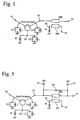
- Fig. 1 shows an equivalent circuit of the non-reciprocal circuit module according to one embodiment of the present invention
- Fig. 2 shows the non-reciprocal circuit module according to one embodiment of the present invention
- Fig. 3 shows the circuit structure of each layer constituting the laminate of the non-reciprocal circuit module of the present invention.
- This non-reciprocal circuit module is provided with the functions of a non-reciprocal circuit and a directional coupler, and operated at the desired impedance Z 0 with an external magnetic field applied from a permanent magnet 9 to a magnetic body 13 in the non-reciprocal circuit portion.
- load capacitors C1 connected between terminals P2, P3, P4 and a ground GND determine the operation frequency of the non-reciprocal circuit.
- the inductance L of the magnetic body 13 encircled by central conductors 14a, 14b and 14c varies by an external magnetic field from the permanent magnet 9.
- a resistor Ri is connected between the terminal P4 and the ground.
- a directional coupler is constituted by a first transmission line 200 placed between the terminal P2 and the terminal P1, and a second transmission line 201 opposing the first transmission line 200 with magnetic coupling and having a terminal P6 connected to a resistor Rc.
- the load capacitors C1 and the first and second transmission lines 200, 201 are formed as laminate constituents by conductor layers placed in the laminate 11 on a resin base 12, and resistors Ri, Rc constituted by printed resistors, chip resistor elements, etc. are placed on the laminate 11.
- the laminate 11 is made of a low-temperature-sinterable, dielectric ceramic material, for instance, a dielectric material having a specific dielectric constant ⁇ r of about 8 and sinterable at 900°C.
- the laminate 11 may be produced, for instance, by forming green sheets each having a thickness of 30-100 ⁇ m by a doctor blade method, printing each green sheet with a conductive paste based on a conductor such as Ag, Cu, etc. to form the first and second transmission lines 200, 201 for the directional coupler and electrodes (conductor layers) for constituting load capacitors for the non-reciprocal circuit, integrally transmission a plurality of conductor-printed green sheets, and sintering the resultant laminate.
- An assembly 10 comprises a central conductor member comprising three central conductors 14a, 14b, 14c integrally radially extending from a ground electrode formed by, for instance, a thin copper plate, and a magnetic body 13 such as a disc-shaped garnet, etc. placed on the ground electrode of the central conductor member.
- the central conductors 14a, 14b, 14c are bent along a side surface of the disc-shaped magnetic body 13, and overlapped each other at a distance of 120° in a mutually insulated manner via an insulating film, etc.
- the assembly 10 is placed in a center pore 15 of the laminate 11.
- One end of the central conductor 14a is connected to an electrode 50a for constituting a load capacitor on an upper surface of the laminate 11, and a central conductor 14b is connected to an electrode 50b.
- One end of the central conductor is connected to an electrode 50c on an upper surface of the laminate 11, and the other end of each central conductor is connected to a ground electrode (conductor plate) 18 on the resin base 12 via a ground electrode positioning on a lower surface of the disc-shaped magnetic body 13.
- the side surface of the resin base 12 is provided with a plurality of external terminals 17a-17f for connecting to a mounting board.
- a sheet-shaped magnetic body may be formed by a sheet-forming technology such as a doctor blade method, etc., and formed with an electrode pattern for a central conductor and integrally laminated and then sintered.
- a central conductor may be formed on a sintered magnetic body by a thin-film technology.
- the non-reciprocal circuit module of the present invention can be obtained.
- the laminate 11 is used for a non-reciprocal circuit module for W-CDMA (wideband CDMA, transmitted frequency TX: 1.92 GHz-1.98 GHz).
- W-CDMA wideband CDMA, transmitted frequency TX: 1.92 GHz-1.98 GHz.
- W-CDMA is taken as an example of a system for a wireless communications device, the same effects of the present invention can be obtained in the other systems.
- the lowermost green sheet 112 is formed with a ground electrode 63 substantially on an entire rear surface, and then with electrodes 80a-80c, which are connected to connection electrodes 30a-30c formed on a resin base 12.
- a green sheet 109 provided with a line electrode 73 for constituting a first transmission line is laminated thereon.
- a green sheet 108 formed with a through-hole electrode shown by a black circle in the figure
- a green sheet 107 formed with a line electrode 72 for constituting the second transmission line and a through-hole electrode One end of the line electrode 72 is connected to an external electrode 19c formed on the side surface of the laminate 11, and one end of the line electrode 73 is connected to an external electrode 19a formed on the side surface of the laminate 11.
- a connection electrode 70 formed on the green sheet 106 has one end connected to a line electrode 73 via a through-hole electrode, and the other end connected to a pattern electrode 50d on an upper surface of the laminate 11 via through-hole electrodes of green sheets 100-105.
- a line electrode 72 is connected to a pattern electrode 50e on an upper surface of the laminate 11 via through-hole electrodes formed in the green sheets 100-106.
- Laminated on the green sheet 106 are a green sheet 105 provided with a ground electrode 62 and through-hole electrodes, a green sheet 104 provided with electrode patterns 52a-52c for load capacitors and through-hole electrodes, a green sheet 103 provided with a ground electrode 61 and through-hole electrodes, a green sheet 102 provided with electrode patterns 51a-51c for load capacitors and through-hole electrodes, a green sheet 101 provided with a ground electrode 60 and through-hole electrodes, and a green sheet 100 provided with electrode patterns 50a-50c for load capacitors, connecting electrodes 50d-50f and through-hole electrodes in this order.
- Load capacitors C1 connected to terminals P3, P2 and P4, respectively are constituted by electrode patterns 50b, 51b, 52b, electrode patterns 50c, 51c, 52c and electrode patterns 50a, 51a, 52a, and ground electrodes 60, 61, 62.
- Resistors Ri, Rc are formed on an upper surface of the laminate 11 by a printing/baking method.
- the resistor Ri is a terminal resistor for an isolator
- the resistor Rc is a terminal resistor for a directional coupler.
- chip resistors may be used, and each resistor may be formed simultaneously with sintering the laminate.
- input/output electrodes 80a, 80b, 80c connected to connection electrodes 30a, 30b, 30c of the resin base 12, and a ground electrode 63 connected to a ground electrode 18 of the resin base 12.
- a dielectric material having a specific dielectric constant ⁇ r of about 8 is used to form the laminate 11, with a distance of 300 ⁇ m between the upper and lower ground electrodes sandwiching the line electrodes, each line electrode having a width of 100 ⁇ m and a line length of about 1/16 wavelength.
- the line electrodes 72, 73 constituting the first and second transmission lines respectively have a one-turn-coil shape, opposing at a distance of 100 ⁇ m via a dielectric layer in a lamination direction to have the coupling of 20 dB. It is preferable that with a directional coupler having such a coil coupling structure, the coupling can easily be controlled by the layer distance between the main line and the sub-line and the line length of their overlapping portion.
- the line electrodes may be turned by one or more times depending on the shape of the laminate 11.
- line electrodes for the directional coupler and electrodes for the load capacitors are formed on separate layers of the laminate with a ground electrode sandwiched therebetween to have decreased interference of these parts.
- the first transmission line (line electrode 73) for the directional coupler and an electrode pattern 50b for the load capacitor are connected on an outer surface of the laminate 11, so that the electric characteristics of the non-reciprocal circuit and the directional coupler can separately be confirmed.
- This makes it possible to easily identify which functional parts are culprits when there are electric malfunctions in the non-reciprocal circuit. For instance, even if a center frequency deviates in the non-reciprocal circuit, such deviation can easily be found.
- electrodes 50a, 50b, 50c for load capacitors formed on an outer surface of the laminate 11 are trimmed to adjust their capacitance, the center frequency can be varied.
- the laminate 11 having an outer size of 4 mm x 3.5 mm x 0.5 mm was obtained.
- an extremely small non-reciprocal circuit module having an equivalent circuit shown in Fig. 1, a structure shown in Fig. 2 and an outer size of 4 mm x 4 mm x 1.7 mm was produced.
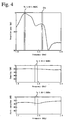
- Figs. 4(a)-(c) show the insertion loss characteristics and coupling characteristics (degree of coupling) of this non-reciprocal circuit module, as well as its isolation characteristics between the output terminal P3 and the input terminal P1.
- the non-reciprocal circuit module of this example has excellent insertion loss characteristics, coupling characteristics and isolation characteristics in a desired frequency band with directivity of 18 dB or more. This indicates that the non-reciprocal circuit module of this example is fully small and high in performance.
- Fig. 5 shows an equivalent circuit of the non-reciprocal circuit module according to another embodiment of the present invention.
- This non-reciprocal circuit module is provided with the function of a directional coupler as well as the function of a low-pass filter.
- Example 1 Because the non-reciprocal circuit module of this example has the same portions as those of Example 1, only different portions are explained here. The differences from Example 1 are; (1) the first and second electrostatic capacitors C3, C4 are connected between both ends of the first transmission line and the ground to constitute a low-pass filter by the first transmission line and the first and second electrostatic capacitors C3, C4, and (2) the third electrostatic capacitor C2 is connected in parallel to the first transmission line to have sharp attenuation.
- Fig. 6 is an exploded perspective view showing the laminate 11 of this example.
- the differences from Example 1 are that an electrode 300 for an electrostatic capacitor C3 is formed on the green sheet 106, that an electrode 400 for an electrostatic capacitor C2 is formed on the green sheet 110, that an electrode 401 for an electrostatic capacitor C2 is formed on the green sheet 111, and that an electrode 301 for an electrostatic capacitor C4 is formed on the green sheet 112.
- the first transmission line 200 can be utilized as an inductor for the low-pass filter, but also the non-reciprocal circuit module can be made multi-functional while maintaining the insertion loss and the size at the same level as Example 1 as compared with when the low-pass filter is simply added to the non-reciprocal circuit module of Example 1. Accordingly, further reduction of the number of parts and decrease in the mounting area can be achieved.
- the line electrode 73 constituting the first transmission line 200 needs only be elongated properly while keeping the opposing relation with the second transmission line 201 to provide the first distributed constant line 200 with inductance as shown in Fig. 8.
- Figs. 7(a)-(c) show the insertion loss characteristics and coupling characteristics of this non-reciprocal circuit module as well as its isolation characteristics between the output terminal P3 and the input terminal P1.
- excellent insertion loss characteristics, coupling characteristics and isolation characteristics are obtained in the desired frequency band, and the second harmonic attenuation is 30 dB or more with directivity of 19 dB or more. This indicates that the non-reciprocal circuit module of this example is sufficiently small and high in performance.
- Examples 1, 2 are directed to the non-reciprocal circuit module for W-CDMA, this example is directed to a non-reciprocal circuit module for D-AMPS (digital-advanced mobile phone service, transmitted frequency TX: 824 MHz-849 MHz).
- D-AMPS digital-advanced mobile phone service, transmitted frequency TX: 824 MHz-849 MHz.
- any of the inductance, load capacitance and line length of a directional coupler should be increased, resulting in difficulty in the miniaturization.
- part of a circular pore 16 of the laminate 11 in this example is buried as shown in Fig. 9.
- This provides advantages of increasing the area of an electrode pattern on the green sheet and the capacitance of the load capacitor C1, thereby stabilizing the ground. Therefore, the magnetic body 13 has a deformed circular shape of 2.5 mm in diameter partially cut by 0.75 mm from a periphery in this Example.
- the internal structure of the laminate 11 is explained in a lamination order referring to Fig. 10.
- the lowermost green sheet 112 is provided with a ground electrode 63 and a pattern electrode connected to a connection electrode formed on the resin base 12 substantially on an entire rear surface.
- One line electrode 73b constituting the second transmission line is formed on the green sheet 112.
- a green sheet 111 formed with another line electrode 73a constituting the second transmission line is laminated on the green sheet 112.
- the green sheet 111 is provided with a through-hole electrode, through which the line electrode 73a is connected to the line electrode 73b, thereby constituting a second transmission line in a one-turn shape.
- Laminated on the green sheet 111 are a green sheet 110 on which an electrode pattern is not printed, and a green sheet 109 formed with a line electrode 72b constituting the first transmission line.
- a green sheet 108 formed with another line electrode 72a constituting the first transmission line is laminated on the green sheet 109.
- the green sheet 108 is provided with a through-hole electrode, through which the line electrode 72a is connected to the line electrode 72b, thereby constituting a first transmission line in a one-turn shape.
- One end of this first transmission line extends to a pattern electrode 50d on an upper surface of the laminate 11 through the through-hole electrodes formed in the green sheets 100-107.
- green sheets 107and 106 both provided with through-hole electrodes, a green sheet 105 provided with a ground electrode 62 and through-hole electrodes, a green sheet 104 provided with electrode patterns 52a-52c for load capacitors and through-hole electrodes, a green sheet 103 provided with a ground electrode 61 and through-hole electrodes, a green sheet 102 provided with electrode patterns 51a-51c for load capacitors and through-hole electrodes, a green sheet 101 provided with a ground electrode 60 and through-hole electrodes, and a green sheet 100 provided with electrode patterns 50a-50c for load capacitors, connecting pattern electrodes 50d, 50f and through-hole electrodes in this order.
- Load capacitors C1 connected to terminals P2, P3 and P4 are constituted by electrode patterns 50b, 51b, 52b, electrode patterns 50c, 51c, 52c and electrode patterns 50a, 51a, 52a, and ground electrode patterns 60, 61, 62.
- a resistor Ri is formed as a terminal resistor for an isolator on an upper surface of the laminate 8 by a printing/baking method.
- a chip resistor may be used in place of the printed resistor, and the resistor Ri may be formed by simultaneously with sintering the laminate.
- a laminate 11 having an outer size of 4 mm x 3.5 mm x 0.5 mm.
- the first transmission line and the second transmission line are placed such that they enclose a pore 16.
- relatively long lines can be formed in a restricted region in the laminate 11. It has thus been found that a distributed constant line can be formed with a line length with only small unevenness in the degree of coupling in a frequency band of a transmitting signal, and that directivity, one of the important characteristics of the directional coupler, is 10 dB or more.
- a dielectric body having a specific dielectric constant ⁇ r of about 8 is used to constitute the laminate 11, with a distance of 400 ⁇ m between the ground electrodes 62, 63 sandwiching the first and second transmission lines, each line electrode having a width of 100 ⁇ m, and the first and second transmission lines having a line length of about 1/12 wavelength.
- the first and second transmission 200, 201 are each in a one-turn coil type, and the closest electrode patterns 72b, 73a among those for the first and second distributed constant lines opposing via a dielectric layer oppose each other by a distance of 100 ⁇ m.
- the coupling of 14.3 dB has been achieved.
- Such a coil coupling structure is preferable, because the degree of coupling can easily be controlled by a layer distance between the main line and the sub-line and a line length of their overlapping portion.
- the line electrodes may be turned one or more times depending on the shape of the laminate 11.
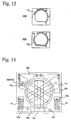
- Fig. 12 is a plan view showing green sheets 108, 109 provided with line electrodes 72a, 72b for constituting the first transmission line 200.
- the first transmission line 200 of this example has line electrodes 72a, 72b formed on two layers and connected via through-hole electrodes as in Example 3. With the positions of through-hole electrodes and the length of line electrodes 72a, 72b properly varied, an area was changed in the closest electrode patterns among those of the first and second transmission lines opposing via a dielectric layer.
- the through-hole electrode is at a point A, B, C or D on the green sheet 108 shown in Fig. 12, it is in contact with a portion at the point A, B, C or D on the green sheet 109.
- a through-hole electrode is formed in a portion B in Example 3.
- the degree of coupling varies from 12.5 dB to 14.3 dB, 14.8 dB and 15.0 dB at each point A-D.
- the degree of coupling can easily be controlled only by adjusting the position of a through-hole in a plane.
- the position of the through-hole electrode in the first transmission line 200 is changed to vary the degree of coupling in this example, the same effects are also obtained by changing the position of a through-hole electrode in the second transmission line 201 or the positions of through-hole electrodes in both first and second distributed constant lines.
- the directivity was 10 dB or more, on the same level as in Example 3.
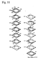
- FIG. 11 A further example of the non-reciprocal circuit module according to the present invention is explained referring to Fig. 11.
- the non-reciprocal circuit module of this example has the same portions as those of the non-reciprocal circuit module of Example 3, only different portions will be explained for the simplicity of explanation.
- the second transmission line 201 was short and formed only on the green sheet 111. With such a structure, the coupling could be decreased to as small as 20.7 dB, lower than in Example 3.
- the directivity was 10 dB or more, though it was poorer than in Example 1.
- FIG. 13 A further example of the non-reciprocal circuit module according to the present invention is explained referring to Fig. 13. Because this example has the same portions as in the above Example, only different portions will be explained for the simplicity of explanation.
- a ground electrode for constituting the load capacitors is divided for every load capacitors, the green sheet 101 is formed with ground electrodes 60a, 60b, 60c, and the green sheet 103 is formed with ground electrodes 61a, 61b, 61c.
- the load capacitor is constituted as a low-loss capacitor.
- Fig. 14 shows an upper surface of the assembly 11.
- One end of the first transmission line 200 extends to the through-hole electrodes on an outer surface of the assembly 11 so that it is connected to an electrode 50d to form a terminal P2 in Fig. 1.
- the directional coupler and the non-reciprocal circuit are in a shut-off state in DC current. Accordingly, after normal operation is confirmed by measuring electric characteristics of the directional coupler, a central conductor 14b of the assembly 10 can be soldered to both electrode pattern 50b and electrode 50d constituting the load capacitors.
Landscapes
- Non-Reversible Transmitting Devices (AREA)
Abstract
An irreversible circuit module
includes a permanent magnet for providing a
DC magnetic field for a magnetic member; an
assembly having a magnetic member provided with
a plurality of conductors being common on one
end and serving as input and output terminals for
high-frequency signals on the other end; a plurality
of load capacitors connected to the conductors, the
load capacitors being formed in a laminate having a
conductor layer, a first transmission line connected
to any of the conductors; and a second transmission
line coupled magnetically to the first transmission
line. The first transmission line and the second transmission line are included in the laminate. The assembly is received in a hole in
the middle of the laminate.
Description
The present invention relates to a non-reciprocal circuit module
such as a circulator, an isolator, etc. used in a microwave communications
equipment, etc. such as a mobile phone, etc.
Wireless communications devices, for instance, mobile phones
have become popular remarkably in recent years with their functions and
services improved increasingly. Taking a mobile phone as an example,
there are various systems for mobile phones, for instance, EGSM (extended
global system for mobile communications) and DCS1800 (digital cellular
system 1800) systems widely used mostly in Europe, a PCS (personal
communications services) system used in the U. S., and a PDC (personal
digital cellular) system used in Japan. In a mobile phone used in such
systems, it is necessary to prevent part of a transmitting output power from
being reflected by the variation of impedance, etc. of an antenna, an
amplifier from being damaged by this reflected electric power, and a signal
of an adjacent channel from entering from an antenna to cause mutual
modulation. It is also regulated, for instance, in PDC, etc. that a signal for
controlling a transmitting output is sent from a base station to mobile
phones to control the transmitting output power of each mobile phone.
Therefore, in a mobile phone having a transmitting circuit means
having a structure shown in Fig. 18, a high-frequency signal from a
modulation circuit (not shown) is amplified by an amplifier 1, and an
output proportional to the high-frequency signal is taken out by a
directional coupler 2 and supplied to an automatic gain control circuit 7 to
control the output power of the amplifier 1. Also, a non-reciprocal circuit
device (isolator) 3 placed on the downstream side of the directional coupler
2 prevents a reflected wave generated by the mismatching, etc. of
characteristic impedance and line impedance in each part (an antenna 6, a
low-pass filter 4 and a duplexer 5) from entering into the amplifier 1.
Fig. 19 is an exploded perspective view showing a conventional
non-reciprocal circuit device. This non-reciprocal circuit device
comprises a central conductor assembly 10, a resin case 12, dielectric
bodies 50a, 50b, 50c constituting load capacitors, a permanent magnet 9,
and metal cases 7, 8. The central conductor assembly 10 comprises an
integral central conductor member constituted by a ground electrode
formed by a thin copper plate and central conductors 14a, 14b, 14c radially
extending therefrom in three directions, and a disc-shaped garnet (magnetic
body) 13, the central conductor member encircling the disc-shaped garnet
(magnetic body) 13, and the central conductors 14a, 14b, 14c being folded
and crossing at 120° with mutual insulation at a center on the upper surface
of the garnet (magnetic body) 13. The central conductor assembly 10 is
placed in a recess 15 substantially at a center of the resin case 12, and the
dielectric bodies 50a, 50b, 50c are placed in three rectangular recesses
around the recess 15. The ground electrode of the central conductor
member is soldered to a ground plate of the resin case 12, and the central
conductors 14a, 14b, 14c (input/output electrodes) of the central conductor
member are soldered to external electrodes of the dielectric bodies 50a, 50b,
50c on their upper surfaces. The permanent magnet 9 for applying a DC
magnetic field to the central conductors 14a, 14b, 14c on the garnet 13 is
placed above the central conductor assembly 10. These parts are entirely
received in a pair of upper and lower metal cases 7, 8. A pair of upper
and lower metal cases 7, 8 also serve as magnetic yokes to constitute a
magnetic circuit, providing a non-reciprocal circuit device having an outer
size of 5 mm x 5 mm x 1.7-2.0 mm.
However, when mobile phone having such a structure comprises a
transmitting circuit means, into which the directional coupler 2, coupling
capacitors, the non-reciprocal circuit device 3 and the low-pass filter 4 are
incorporated as separate parts, there arise disadvantages described below.
Demand has been increasingly higher for mobile phones to make
areas occupied by the directional coupler 2, the low-pass filter 4 and the
amplifier 1 as small as possible for miniaturization, and to reduce the cost
per function and the number of parts as much as possible for price
reduction. Under such demand, though areas occupied by the directional
coupler 2, the non-reciprocal circuit device 3, the low-pass filter 4 and the
amplifier 1 can be reduced by miniaturizing these parts, such means has its
own limits. In addition, if the non-reciprocal circuit device 3 is tried to be
miniaturized simply by the miniaturization of the central conductor
assembly 10 and the dielectric bodies 50a, 50b, 50c, there would arise the
following problems: If the central conductor assembly 10 is miniaturized,
the non-reciprocal circuit device deviates from the optimally operable size
as a magnetic body. In addition, if a dielectric material having a high
dielectric constant is used to miniaturize the dielectric body, loss by the
dielectric material increases relatively, resulting in deterioration in electric
characteristics as the non-reciprocal circuit device.
If miniaturized, the directional coupler 2 has extremely
deteriorated isolation characteristics. Because of the deterioration of
isolation characteristics, directivity, one of the important characteristics of
the directional coupler 2, cannot sufficiently be obtained. As a result, part
or all of the reflected wave in a direction opposite to the traveling direction
of the transmitting signal flows into the coupling terminal P5, failing to
obtain the desired degree of coupling. Further, a new matching circuit
should sometimes be added to achieve impedance matching between the
directional coupler and the non-reciprocal circuit device. Incidentally, the
directivity is determined by the following equation:
Directivity = isolation between output terminal and coupling terminal
- amount of coupling,
which should be at least 10 dB or more.
Further, the directional coupler 2 suffers from an insertion loss,
which mainly comprises coupling loss and conductor loss, and the
non-reciprocal circuit device 3 and the low-pass filter 4 have insertion loss.
Accordingly, when they are used as separate parts, the loss of each part is
accumulated, resulting in large loss in the overall transmitting circuit means.
Loss in the transmitting circuit means leads to increase in power
consumption, and this loss is not ignorable for mobile phones having
limited battery capacities.
To solve such problems, Japanese Patent Laid-Open No.
9-270608 proposes that output in proportion to a high-frequency signal is
taken out from a capacitor (output-detecting capacitance) branched from
the input terminal of an isolator, that the output is supplied to an automatic
gain control circuit to control the output power of an amplifier, and that the
output-detecting capacitor is formed in an integral laminate constituted by
laminating dielectric sheets together with load capacitors of the isolator.
However, when the output-detecting capacitance is used,
sufficient directivity cannot be obtained due to the influence of parasitic
capacitance. Therefore, unless an output-detecting capacitor designed by
taking interference between electrode patterns into sufficient consideration
is formed in the laminate, the desired coupling would not be obtained.
When the coupling of 20 dB is sought, the output-detecting capacitance
should be as small as 0.15 pF, resulting in difficulty in control, and large
variation in the coupling due to unevenness in production and parasitic
capacitance. In addition, the interference between electrode patterns
makes further miniaturization substantially difficult.
Accordingly, an object of the present invention is to provide a
non-reciprocal circuit module having the functions of a non-reciprocal
circuit device and a directional coupler to suppress the number and area of
parts mounted and production cost.
Another object of the present invention is to provide a
non-reciprocal circuit module with small loss and further provided with the
function of a low-pass filter.
A further object of the present invention is to provide a
non-reciprocal circuit module provided with a high-frequency power
amplifier.
The first non-reciprocal circuit module of the present invention
comprises (a) a permanent magnet for applying a DC magnetic field to a
magnetic body, (b) an assembly comprising a plurality of central
conductors and the magnetic body placed therein, each of the central
conductors having a common terminal at one end and an input/output
terminal for a high-frequency signal at the other end, (c) a plurality of load
capacitors formed in a laminate constituted by a plurality of dielectric
layers having conductor layers and connected to the central conductor, (d) a
first transmission line connected to any one of the central conductors, and
(e) a second transmission line magnetically coupled to the first
transmission line, the first transmission line and the second transmission
line being formed in the laminate.
In this non-reciprocal circuit module, a high-frequency signal
from an amplifier is supplied to the terminal P1 of the first transmission
line formed in the laminate. The second transmission line is formed in the
laminate such that it is magnetically coupled to the first transmission line.
As a result, part of the high-frequency signal appears on the second
transmission line, whereby high-frequency electric power in proportion to
the high-frequency signal is supplied from a terminal P5 formed in the
non-reciprocal circuit module to the automatic gain control circuit. On
the other hand, the high-frequency signal is transmitted to the terminal P2
and then supplied to the non-reciprocal circuit device. The
high-frequency signal supplied through the terminal P2 is transmitted to the
garnet via the central conductor in the assembly, in which the traveling
direction of the high-frequency signal is turned by 120° under the function
of a DC magnetic field applied from the permanent magnet to the garnet.
As a result, the high-frequency signal is transmitted to the central
conductor connected to the terminal P3, from which it is output.
The first and second transmission lines cooperating to constitute
the directional coupler are formed as laminate constituents in the laminate
constituted by a plurality of dielectric layers having conductor layers,
together with a plurality of load capacitors constituting the non-reciprocal
circuit device. With this structure, impedance matching between the
non-reciprocal circuit device and the directional coupler can easily be
achieved.
The impedance of the directional coupler is determined by the
width of a transmission line constituting the directional coupler, and its
distance from the ground surface, etc. The impedance of the
non-reciprocal circuit device is determined by the materials and shapes of
the magnetic body and the central conductors constituting the central
conductor assembly, and the magnetic force of the permanent magnet.
Though the characteristic impedance of the directional coupler and the
non-reciprocal circuit device is generally set at 50 Ω, it inevitably varies to
some extent when the directional coupler and the non-reciprocal circuit
device are constituted as separate devices, due to inevitable unevenness in
production, for instance, unevenness in the thickness of the dielectric layer,
the line width of the transmission line, the magnetic force of the magnetic
body, etc.
Accordingly, simple combination of the directional coupler and
the non-reciprocal circuit device causes impedance mismatching at the
input/output terminal P2, resulting in deterioration in insertion loss
characteristics. However, when two transmission lines constituting the
directional couplers and load capacitors constituting the non-reciprocal
circuit device are integrally formed in the laminate , the characteristic
impedance of the non-reciprocal circuit device can be matched to that of
the directional coupler by adjusting the DC magnetic field from the
permanent magnet, thereby extremely reducing the impedance
mismatching at the terminal P2. In addition, by forming the load
capacitors and the first and second transmission lines as laminate
constituents in the laminate constituted by a plurality of dielectric layers
having conductor layers, the non-reciprocal circuit module can be
miniaturized.
The second non-reciprocal circuit module of the present invention
comprises (a) a permanent magnet for applying a DC magnetic field to a
magnetic body, (b) an assembly comprising a plurality of central
conductors and the magnetic body placed therein, each of the central
conductors having a common terminal at one end and an input/output
terminal for a high-frequency signal at the other end, and (c) a laminate
comprising a plurality of load capacitors formed by conductor layers
electrically connected to the assembly and each opposing via a dielectric
layer, a first transmission line connected to any one of the central
conductors, and a second transmission line magnetically coupled to the first
transmission line, the conductor layers on the hot side and the ground side
for the plural load capacitors being divided for every load capacitor.
This non-reciprocal circuit module exhibits the same effects as the
first non-reciprocal circuit module, and has low loss with the conductor
layers on the hot side and the ground side for the plural load capacitors
divided for every load capacitor, thereby preventing the inductance
parasitic to the load capacitors and equivalent series resistance from
increasing to keep the load capacitor at a high Q value (low loss).
The laminate has a pore for receiving the assembly substantially
at center. This pore may be a through-hole or a recess.
The third non-reciprocal circuit module of the present invention
comprises (a) a permanent magnet for applying a DC magnetic field to a
plate-shaped magnetic body, (b) an assembly comprising a central
conductor member having central conductors extending from a ground
electrode formed by a thin copper plate radially in a plurality of directions,
and the magnetic body, the central conductors encircling the magnetic body
in a mutually insulated manner and crossing substantially at the center of
the magnetic body, and (c) a laminate constituted by a plurality of dielectric
layers having conductor layers and having a pore for receiving the
assembly substantially at center, the laminate comprising a plurality of load
capacitors each formed by conductor layers opposing via the dielectric
layer around the pore, a first transmission line connected to any one of the
central conductors, and a second transmission line magnetically coupled to
the first transmission line, the load capacitors being electrically connected
to the assembly, such that one of the load capacitors is electrically
connected to the first transmission line via the central conductor, while the
other load capacitors are not connected to the first transmission line.
In addition to the above effects, such a structure makes it possible
to separately confirm the electric characteristics of the non-reciprocal
circuit and the directional coupler. Accordingly, when electric troubles
take place in the non-reciprocal circuit module, it is possible to easily
identify which functioning parts are culprits.
In the non-reciprocal circuit module of the present invention, it is
preferable that an electrostatic capacitor is connected to at least one end of
the first transmission line in parallel with the load capacitor to constitute
the low-pass filter. It is also preferable that an electrostatic capacitor is
connected in parallel to the first transmission line to constitute a parallel
resonance circuit, and that an attenuation pole is provided at a resonance
frequency of the parallel resonance circuit. Thus, by integrating the
low-pass filter with the directional coupler, the number of circuit elements
can be reduced than when the low-pass filter and the directional coupler are
separately connected, thereby achieving the miniaturization of the overall
high-frequency circuit with low loss as a whole because the insertion loss is
caused only by the directional coupler.
In the present invention, each load capacitor is preferably
constituted by conductor layers opposing via a dielectric layer in a
lamination direction, part of the conductor layers being formed on a main
surface of the laminate opposing to the permanent magnet. With such a
structure, even with deviated center frequency of the non-reciprocal circuit,
the capacitance can be controlled by trimming part of the conductor layers.
In the present invention, the first and second transmission lines
constituting the directional coupler are opposing via a dielectric layer in a
lamination direction. Such a structure needs smaller planar area than
when the directional coupler is constituted by placing two transmission
lines on the same plane. Further, winding the transmission line in a coil
shape can preferably prevent the variation of coupling by positional
deviation at the time of lamination.
The first and/or second transmission line may be constituted by
electrically connecting a plurality of conductor layers formed on the
different dielectric layers via through-holes. The coupling of the
directional coupler can be controlled by adjusting the overlapping area of
the conductor layers for the first and second transmission lines opposing
via a dielectric layer in a lamination direction.
Provided on a rear surface of the laminate used in the
non-reciprocal circuit module of the present invention is a wide ground
electrode formed by a conductor layer, and the ground electrode serves as a
common ground for the first and second transmission lines and the load
capacitors. With such a structure, the ground potential of the laminate can
easily be taken with sufficient bonding strength by soldering.
In the laminate according to one preferred embodiment of the
present invention, to prevent interference between the first and second t
transmission lines and the non-reciprocal circuit, conductor layers
constituting the first and second transmission lines are formed in a first
laminate region, while a plurality of load capacitors constituting the
non-reciprocal circuit are formed in a second laminate region different from
the first laminate region.
To prevent interference, the first and second transmission lines
may be placed such that they do not overlap conductor layers constituting
the load capacitor in a lamination direction, or the first laminate region may
be separated from the second laminate region by the ground electrode.
In the present invention, the high-frequency amplifier can be
mounted onto the laminate. The output terminal of the high-frequency
amplifier is connected to one end of the first transmission line by conductor
layers in the laminate. The high-frequency amplifier comprises an
amplifier circuit having a transistor, an input-matching circuit connected to
the input terminal of the amplifier circuit, and an output-matching circuit
connected to the output terminal of the amplifier circuit, the input-matching
circuit and the output-matching circuit each having a capacitor and an
inductor. It is preferable that the transistor of the amplifier circuit is
mounted onto the laminate, while the inductor is formed as a transmission
line in the laminate. The capacitor is preferably formed by capacitor
electrodes opposing via a dielectric layer in the laminate. The transistor
of the amplifier circuit is preferably a field effect transistor, and the
high-frequency amplifier is preferably constituted by a transistor made of
gallium arsenide GaAs, these parts being mounted onto the laminate.
The characteristic impedance of the non-reciprocal circuit is set at
50 Ω, while the input/output impedance of the transistor is about several Ω
to several tens of Ω, needing input/output-matching circuits for connection
therebetween. However, when a low-pass filter is used as an
output-matching circuit connected to the output terminal of the amplifier
circuit as shown in the equivalent circuit of Fig. 17, the number of circuit
elements can be reduced as compared with when the output-matching
circuit is mounted separately, resulting in improvement in the insertion loss
characteristics.
Referring to the attached drawings, the specific structure of the
non-reciprocal circuit module of the present invention will be explained
below.
Fig. 1 shows an equivalent circuit of the non-reciprocal circuit
module according to one embodiment of the present invention, Fig. 2
shows the non-reciprocal circuit module according to one embodiment of
the present invention, and Fig. 3 shows the circuit structure of each layer
constituting the laminate of the non-reciprocal circuit module of the present
invention. This non-reciprocal circuit module is provided with the
functions of a non-reciprocal circuit and a directional coupler, and operated
at the desired impedance Z0 with an external magnetic field applied from a
permanent magnet 9 to a magnetic body 13 in the non-reciprocal circuit
portion.
In Fig. 1, load capacitors C1 connected between terminals P2, P3,
P4 and a ground GND determine the operation frequency of the
non-reciprocal circuit. The inductance L of the magnetic body 13
encircled by central conductors 14a, 14b and 14c varies by an external
magnetic field from the permanent magnet 9. To operate this
non-reciprocal circuit as an isolator, a resistor Ri is connected between the
terminal P4 and the ground. A directional coupler is constituted by a first
transmission line 200 placed between the terminal P2 and the terminal P1,
and a second transmission line 201 opposing the first transmission line 200
with magnetic coupling and having a terminal P6 connected to a resistor
Rc.
The load capacitors C1 and the first and second transmission lines
200, 201 are formed as laminate constituents by conductor layers placed in
the laminate 11 on a resin base 12, and resistors Ri, Rc constituted by
printed resistors, chip resistor elements, etc. are placed on the laminate 11.
The laminate 11 is made of a low-temperature-sinterable,
dielectric ceramic material, for instance, a dielectric material having a
specific dielectric constant εr of about 8 and sinterable at 900°C. The
laminate 11 may be produced, for instance, by forming green sheets each
having a thickness of 30-100 µm by a doctor blade method, printing each
green sheet with a conductive paste based on a conductor such as Ag, Cu,
etc. to form the first and second transmission lines 200, 201 for the
directional coupler and electrodes (conductor layers) for constituting load
capacitors for the non-reciprocal circuit, integrally transmission a plurality
of conductor-printed green sheets, and sintering the resultant laminate.
An assembly 10 comprises a central conductor member
comprising three central conductors 14a, 14b, 14c integrally radially
extending from a ground electrode formed by, for instance, a thin copper
plate, and a magnetic body 13 such as a disc-shaped garnet, etc. placed on
the ground electrode of the central conductor member. The central
conductors 14a, 14b, 14c are bent along a side surface of the disc-shaped
magnetic body 13, and overlapped each other at a distance of 120° in a
mutually insulated manner via an insulating film, etc. The assembly 10 is
placed in a center pore 15 of the laminate 11. One end of the central
conductor 14a is connected to an electrode 50a for constituting a load
capacitor on an upper surface of the laminate 11, and a central conductor
14b is connected to an electrode 50b. One end of the central conductor is
connected to an electrode 50c on an upper surface of the laminate 11, and
the other end of each central conductor is connected to a ground electrode
(conductor plate) 18 on the resin base 12 via a ground electrode positioning
on a lower surface of the disc-shaped magnetic body 13. The side surface
of the resin base 12 is provided with a plurality of external terminals
17a-17f for connecting to a mounting board.
The assembly 10 can be produced by other methods than the
above one. For instance, as shown in Figs. 15 and 16, a sheet-shaped
magnetic body may be formed by a sheet-forming technology such as a
doctor blade method, etc., and formed with an electrode pattern for a
central conductor and integrally laminated and then sintered. Also, a
central conductor may be formed on a sintered magnetic body by a
thin-film technology.
By disposing the assembly 10 in a pore 15 of the laminate 11,
placing a magnet 9 for applying a DC magnetic field to the assembly 10
thereon, and vertically enclosing them by metal cases 7, 8 serving as
magnetic yokes, the non-reciprocal circuit module of the present invention
can be obtained.
One example of the internal structure of the laminate 11 will be
explained in a lamination order referring to Fig. 3. The laminate 11 is
used for a non-reciprocal circuit module for W-CDMA (wideband CDMA,
transmitted frequency TX: 1.92 GHz-1.98 GHz). For the simplicity of
explanation, W-CDMA is taken as an example of a system for a wireless
communications device, the same effects of the present invention can be
obtained in the other systems.
First, the lowermost green sheet 112 is formed with a ground
electrode 63 substantially on an entire rear surface, and then with
electrodes 80a-80c, which are connected to connection electrodes 30a-30c
formed on a resin base 12. After green sheets 111, 110 on which electrode
patterns are not printed are laminated on the green sheet 112, a green sheet
109 provided with a line electrode 73 for constituting a first transmission
line is laminated thereon. Laminated thereon are a green sheet 108
formed with a through-hole electrode (shown by a black circle in the
figure), and then a green sheet 107 formed with a line electrode 72 for
constituting the second transmission line and a through-hole electrode.
One end of the line electrode 72 is connected to an external electrode 19c
formed on the side surface of the laminate 11, and one end of the line
electrode 73 is connected to an external electrode 19a formed on the side
surface of the laminate 11.
A connection electrode 70 formed on the green sheet 106 has one
end connected to a line electrode 73 via a through-hole electrode, and the
other end connected to a pattern electrode 50d on an upper surface of the
laminate 11 via through-hole electrodes of green sheets 100-105. A line
electrode 72 is connected to a pattern electrode 50e on an upper surface of
the laminate 11 via through-hole electrodes formed in the green sheets
100-106.
Laminated on the green sheet 106 are a green sheet 105 provided
with a ground electrode 62 and through-hole electrodes, a green sheet 104
provided with electrode patterns 52a-52c for load capacitors and
through-hole electrodes, a green sheet 103 provided with a ground
electrode 61 and through-hole electrodes, a green sheet 102 provided with
electrode patterns 51a-51c for load capacitors and through-hole electrodes,
a green sheet 101 provided with a ground electrode 60 and through-hole
electrodes, and a green sheet 100 provided with electrode patterns 50a-50c
for load capacitors, connecting electrodes 50d-50f and through-hole
electrodes in this order.
Load capacitors C1 connected to terminals P3, P2 and P4,
respectively are constituted by electrode patterns 50b, 51b, 52b, electrode
patterns 50c, 51c, 52c and electrode patterns 50a, 51a, 52a, and ground
electrodes 60, 61, 62.
Resistors Ri, Rc are formed on an upper surface of the laminate
11 by a printing/baking method. The resistor Ri is a terminal resistor for
an isolator, and the resistor Rc is a terminal resistor for a directional coupler.
In place of the printed resistors chip resistors may be used, and each
resistor may be formed simultaneously with sintering the laminate.
Formed on a lower surface of the laminate 11 are input/ output
electrodes 80a, 80b, 80c connected to connection electrodes 30a, 30b, 30c
of the resin base 12, and a ground electrode 63 connected to a ground
electrode 18 of the resin base 12.
To achieve the good function of the directional coupler, it is
important that inter-layer distances between a line electrode 73 as a main
line and a ground electrode 63, and between a line electrode 72 as a
sub-line and a ground electrode 62, and their line widths are properly set to
maintain the characteristic impedance of lines at 50 Ω. In this example, a
dielectric material having a specific dielectric constant εr of about 8 is used
to form the laminate 11, with a distance of 300 µm between the upper and
lower ground electrodes sandwiching the line electrodes, each line
electrode having a width of 100 µm and a line length of about 1/16
wavelength.
The line electrodes 72, 73 constituting the first and second
transmission lines respectively have a one-turn-coil shape, opposing at a
distance of 100 µm via a dielectric layer in a lamination direction to have
the coupling of 20 dB. It is preferable that with a directional coupler
having such a coil coupling structure, the coupling can easily be controlled
by the layer distance between the main line and the sub-line and the line
length of their overlapping portion. Of course, the line electrodes may be
turned by one or more times depending on the shape of the laminate 11.
In the laminate of this example, line electrodes for the directional coupler
and electrodes for the load capacitors are formed on separate layers of the
laminate with a ground electrode sandwiched therebetween to have
decreased interference of these parts.
The first transmission line (line electrode 73) for the directional
coupler and an electrode pattern 50b for the load capacitor are connected
on an outer surface of the laminate 11, so that the electric characteristics of
the non-reciprocal circuit and the directional coupler can separately be
confirmed. This makes it possible to easily identify which functional
parts are culprits when there are electric malfunctions in the non-reciprocal
circuit. For instance, even if a center frequency deviates in the
non-reciprocal circuit, such deviation can easily be found. In addition, if
electrodes 50a, 50b, 50c for load capacitors formed on an outer surface of
the laminate 11 are trimmed to adjust their capacitance, the center
frequency can be varied.
Thus, the laminate 11 having an outer size of 4 mm x 3.5 mm x
0.5 mm was obtained. Using the laminate 11, an extremely small
non-reciprocal circuit module having an equivalent circuit shown in Fig. 1,
a structure shown in Fig. 2 and an outer size of 4 mm x 4 mm x 1.7 mm
was produced.
Figs. 4(a)-(c) show the insertion loss characteristics and coupling
characteristics (degree of coupling) of this non-reciprocal circuit module,
as well as its isolation characteristics between the output terminal P3 and
the input terminal P1. As is clear from Figs. 4(a)-(c), the non-reciprocal
circuit module of this example has excellent insertion loss characteristics,
coupling characteristics and isolation characteristics in a desired frequency
band with directivity of 18 dB or more. This indicates that the
non-reciprocal circuit module of this example is fully small and high in
performance.
Fig. 5 shows an equivalent circuit of the non-reciprocal circuit
module according to another embodiment of the present invention. This
non-reciprocal circuit module is provided with the function of a directional
coupler as well as the function of a low-pass filter.
Because the non-reciprocal circuit module of this example has the
same portions as those of Example 1, only different portions are explained
here. The differences from Example 1 are; (1) the first and second
electrostatic capacitors C3, C4 are connected between both ends of the first
transmission line and the ground to constitute a low-pass filter by the first
transmission line and the first and second electrostatic capacitors C3, C4,
and (2) the third electrostatic capacitor C2 is connected in parallel to the
first transmission line to have sharp attenuation.
Fig. 6 is an exploded perspective view showing the laminate 11 of
this example. The differences from Example 1 are that an electrode 300
for an electrostatic capacitor C3 is formed on the green sheet 106, that an
electrode 400 for an electrostatic capacitor C2 is formed on the green sheet
110, that an electrode 401 for an electrostatic capacitor C2 is formed on the
green sheet 111, and that an electrode 301 for an electrostatic capacitor C4
is formed on the green sheet 112. With such a structure, the first
transmission line 200 can be utilized as an inductor for the low-pass filter,
but also the non-reciprocal circuit module can be made multi-functional
while maintaining the insertion loss and the size at the same level as
Example 1 as compared with when the low-pass filter is simply added to
the non-reciprocal circuit module of Example 1. Accordingly, further
reduction of the number of parts and decrease in the mounting area can be
achieved.
When the first transmission line 200 fails to provide sufficient
inductance as a low-pass filter, the line electrode 73 constituting the first
transmission line 200 needs only be elongated properly while keeping the
opposing relation with the second transmission line 201 to provide the first
distributed constant line 200 with inductance as shown in Fig. 8.
Figs. 7(a)-(c) show the insertion loss characteristics and coupling
characteristics of this non-reciprocal circuit module as well as its isolation
characteristics between the output terminal P3 and the input terminal P1.
As is clear from Figs. 7(a)-(c), excellent insertion loss characteristics,
coupling characteristics and isolation characteristics are obtained in the
desired frequency band, and the second harmonic attenuation is 30 dB or
more with directivity of 19 dB or more. This indicates that the
non-reciprocal circuit module of this example is sufficiently small and high
in performance.
Though Examples 1, 2 are directed to the non-reciprocal circuit
module for W-CDMA, this example is directed to a non-reciprocal circuit
module for D-AMPS (digital-advanced mobile phone service, transmitted
frequency TX: 824 MHz-849 MHz).
In general, as a frequency handled decreases, any of the
inductance, load capacitance and line length of a directional coupler should
be increased, resulting in difficulty in the miniaturization. Thus, part of a
circular pore 16 of the laminate 11 in this example is buried as shown in
Fig. 9. This provides advantages of increasing the area of an electrode
pattern on the green sheet and the capacitance of the load capacitor C1,
thereby stabilizing the ground. Therefore, the magnetic body 13 has a
deformed circular shape of 2.5 mm in diameter partially cut by 0.75 mm
from a periphery in this Example.
The internal structure of the laminate 11 is explained in a
lamination order referring to Fig. 10. The lowermost green sheet 112 is
provided with a ground electrode 63 and a pattern electrode connected to a
connection electrode formed on the resin base 12 substantially on an entire
rear surface. One line electrode 73b constituting the second transmission
line is formed on the green sheet 112. A green sheet 111 formed with
another line electrode 73a constituting the second transmission line is
laminated on the green sheet 112. The green sheet 111 is provided with a
through-hole electrode, through which the line electrode 73a is connected
to the line electrode 73b, thereby constituting a second transmission line in
a one-turn shape.
Laminated on the green sheet 111 are a green sheet 110 on which
an electrode pattern is not printed, and a green sheet 109 formed with a line
electrode 72b constituting the first transmission line. A green sheet 108
formed with another line electrode 72a constituting the first transmission
line is laminated on the green sheet 109. The green sheet 108 is provided
with a through-hole electrode, through which the line electrode 72a is
connected to the line electrode 72b, thereby constituting a first transmission
line in a one-turn shape. One end of this first transmission line extends to
a pattern electrode 50d on an upper surface of the laminate 11 through the
through-hole electrodes formed in the green sheets 100-107.
Laminated on the green sheet 108 are green sheets 107and 106
both provided with through-hole electrodes, a green sheet 105 provided
with a ground electrode 62 and through-hole electrodes, a green sheet 104
provided with electrode patterns 52a-52c for load capacitors and
through-hole electrodes, a green sheet 103 provided with a ground
electrode 61 and through-hole electrodes, a green sheet 102 provided with
electrode patterns 51a-51c for load capacitors and through-hole electrodes,
a green sheet 101 provided with a ground electrode 60 and through-hole
electrodes, and a green sheet 100 provided with electrode patterns 50a-50c
for load capacitors, connecting pattern electrodes 50d, 50f and through-hole
electrodes in this order.
Load capacitors C1 connected to terminals P2, P3 and P4 are
constituted by electrode patterns 50b, 51b, 52b, electrode patterns 50c, 51c,
52c and electrode patterns 50a, 51a, 52a, and ground electrode patterns 60,
61, 62.
A resistor Ri is formed as a terminal resistor for an isolator on an
upper surface of the laminate 8 by a printing/baking method. A chip
resistor may be used in place of the printed resistor, and the resistor Ri may
be formed by simultaneously with sintering the laminate.
Thus obtained is a laminate 11 having an outer size of 4 mm x 3.5
mm x 0.5 mm. In this example, the first transmission line and the second
transmission line are placed such that they enclose a pore 16. With such a
structure, relatively long lines can be formed in a restricted region in the
laminate 11. It has thus been found that a distributed constant line can be
formed with a line length with only small unevenness in the degree of
coupling in a frequency band of a transmitting signal, and that directivity,
one of the important characteristics of the directional coupler, is 10 dB or
more.
In this example, a dielectric body having a specific dielectric
constant εr of about 8 is used to constitute the laminate 11, with a distance
of 400 µm between the ground electrodes 62, 63 sandwiching the first and
second transmission lines, each line electrode having a width of 100 µm,
and the first and second transmission lines having a line length of about
1/12 wavelength. Also, the first and second transmission 200, 201 are
each in a one-turn coil type, and the closest electrode patterns 72b, 73a
among those for the first and second distributed constant lines opposing via
a dielectric layer oppose each other by a distance of 100 µm. Thus
obtained is an extremely small non-reciprocal circuit module having the
function of a directional coupler and an outer size of 4 mm x 4 mm x 1.7
mm.
With the above structure, the coupling of 14.3 dB has been
achieved. Such a coil coupling structure is preferable, because the degree
of coupling can easily be controlled by a layer distance between the main
line and the sub-line and a line length of their overlapping portion. Of
course, the line electrodes may be turned one or more times depending on
the shape of the laminate 11.
A further example of the non-reciprocal circuit module of the
present invention is explained referring to Fig. 12. Because the
non-reciprocal circuit module of this example has the same portions as
those of the non-reciprocal circuit module of Example 3, only different
portions will be explained for the simplicity of explanation. Fig. 12 is a
plan view showing green sheets 108, 109 provided with line electrodes 72a,
72b for constituting the first transmission line 200.
The first transmission line 200 of this example has line electrodes
72a, 72b formed on two layers and connected via through-hole electrodes
as in Example 3. With the positions of through-hole electrodes and the
length of line electrodes 72a, 72b properly varied, an area was changed in
the closest electrode patterns among those of the first and second
transmission lines opposing via a dielectric layer. When the through-hole
electrode is at a point A, B, C or D on the green sheet 108 shown in Fig. 12,
it is in contact with a portion at the point A, B, C or D on the green sheet
109. Incidentally, a through-hole electrode is formed in a portion B in
Example 3.
As a result of measuring the variation of the degree of coupling of
the directional coupler by changing the position of the through-hole
electrode, it has been found that the degree of coupling varies from 12.5 dB
to 14.3 dB, 14.8 dB and 15.0 dB at each point A-D. Thus, the degree of
coupling can easily be controlled only by adjusting the position of a
through-hole in a plane.
Though the position of the through-hole electrode in the first
transmission line 200 is changed to vary the degree of coupling in this
example, the same effects are also obtained by changing the position of a
through-hole electrode in the second transmission line 201 or the positions
of through-hole electrodes in both first and second distributed constant
lines. The directivity was 10 dB or more, on the same level as in Example
3.
A further example of the non-reciprocal circuit module according
to the present invention is explained referring to Fig. 11. The
non-reciprocal circuit module of this example has the same portions as
those of the non-reciprocal circuit module of Example 3, only different
portions will be explained for the simplicity of explanation. In the
laminate shown in Fig. 11, the second transmission line 201 was short and
formed only on the green sheet 111. With such a structure, the coupling
could be decreased to as small as 20.7 dB, lower than in Example 3. The
directivity was 10 dB or more, though it was poorer than in Example 1.
A further example of the non-reciprocal circuit module according
to the present invention is explained referring to Fig. 13. Because this
example has the same portions as in the above Example, only different
portions will be explained for the simplicity of explanation. In the
example shown in Fig. 13, a ground electrode for constituting the load
capacitors is divided for every load capacitors, the green sheet 101 is
formed with ground electrodes 60a, 60b, 60c, and the green sheet 103 is
formed with ground electrodes 61a, 61b, 61c. Thus, the load capacitor is
constituted as a low-loss capacitor.
Fig. 14 shows an upper surface of the assembly 11. One end of
the first transmission line 200 extends to the through-hole electrodes on an
outer surface of the assembly 11 so that it is connected to an electrode 50d
to form a terminal P2 in Fig. 1. With such a structure, the directional
coupler and the non-reciprocal circuit are in a shut-off state in DC current.
Accordingly, after normal operation is confirmed by measuring electric
characteristics of the directional coupler, a central conductor 14b of the
assembly 10 can be soldered to both electrode pattern 50b and electrode
50d constituting the load capacitors.
In this example, too, a small non-reciprocal circuit module having
excellent electric characteristics can be obtained as in the other examples.
Claims (17)
- A non-reciprocal circuit module comprising (a) a permanent magnet for applying a DC magnetic field to a magnetic body, (b) an assembly comprising a plurality of central conductors and said magnetic body placed therein, each of said central conductors having a common terminal at one end and an input/output terminal for a high-frequency signal at the other end, (c) a plurality of load capacitors formed in a laminate constituted by a plurality of dielectric layers having conductor layers and connected to said central conductors, (d) a first transmission line connected to any one of said central conductors, and (e) a second transmission line magnetically coupled to said first transmission line, said first and second transmission lines being formed in said laminate.
- The non-reciprocal circuit module according to claim 1, wherein said laminate has a pore for receiving said assembly substantially at center.
- A non-reciprocal circuit module comprising (a) a permanent magnet for applying a DC magnetic field to a magnetic body, (b) an assembly comprising a plurality of central conductors and said magnetic body placed therein, each of said central conductors having a common terminal at one end and an input/output terminal for a high-frequency signal at the other end, and (c) a laminate comprising a plurality of load capacitors formed by conductor layers electrically connected to said assembly and each opposing via a dielectric layer, a first transmission line connected to any one of said central conductors, and a second transmission line magnetically coupled to said first transmission line, the conductor layers of said plural load capacitors on the hot side and the ground side being divided for every load capacitor.
- The non-reciprocal circuit module according to claim 1, wherein said laminate has a pore for receiving said assembly substantially at center.
- A non-reciprocal circuit module comprising (a) a permanent magnet for applying a DC magnetic field to a plate-shaped magnetic body, (b) an assembly comprising a central conductor member comprising central conductors extending from a ground electrode formed by a thin copper plate radially in a plurality of directions, and said magnetic body, said central conductors encircling said magnetic body in a mutually insulated manner and crossing substantially at the center of said magnetic body, and (c) a laminate formed by a plurality of dielectric layers having conductor layers and having a pore for receiving said assembly substantially at center, said laminate comprising a plurality of load capacitors each formed by conductor layers opposing via said dielectric layer around said pore, a first transmission line connected to any one of said central conductors, a second transmission line magnetically coupled to said first transmission line, said load capacitors being electrically connected to said assembly, such that one of said load capacitors is electrically connected to said first transmission line via said central conductors, while the other load capacitors are not connected to said first transmission line.
- The non-reciprocal circuit module according to any one of claims 1-5, wherein an electrostatic capacitor is connected to at least one end of said first transmission line in parallel with said load capacitors, thereby constituting a low-pass filter.
- The non-reciprocal circuit module according to claim 6, wherein an electrostatic capacitor is connected in parallel with said first transmission line to constitute a parallel resonance circuit, which has an attenuation pole at a resonance frequency thereof.
- The non-reciprocal circuit module according to any one of claims 1-7, wherein said load capacitors are constituted by conductor layers opposing via said dielectric layer in a lamination direction, part of said conductor layers being formed on a main surface of said laminate opposing to said permanent magnet.
- The non-reciprocal circuit module according to any one of claims 1-8, wherein said first transmission line is opposing said second transmission line via said dielectric layer in a lamination direction.
- The non-reciprocal circuit module according to any one of claims 1-9, wherein said first and/or second transmission line is formed by electrically connecting a plurality of divided conductor layers placed on a plurality of dielectric layers via through-holes.
- The non-reciprocal circuit module according to any one of claims 1-10, wherein conductor layers constituting said first and second transmission lines have areas overlapping in a lamination direction, which are changed to adjust the degree of coupling.
- The non-reciprocal circuit module according to any one of claims 1-11, wherein a ground electrode is constituted by a wide conductor layer on a rear surface of said laminate, said ground electrode being a common ground for said first and second transmission lines and said load capacitors.
- The non-reciprocal circuit module according to any one of claims 1-12, wherein said laminate has a first laminate region in which conductor layers constituting said first and second transmission lines are formed, and a second laminate region in which a plurality of load capacitors constituting a non-reciprocal circuit are formed.
- The non-reciprocal circuit module according to any one of claims 1-13, wherein said first and second transmission lines are placed such that they do not overlap with conductor layers constituting said load capacitors in a lamination direction.
- The non-reciprocal circuit module according to any one of claims 1-14, wherein said laminate further comprises a high-frequency amplifier, an output terminal of said high-frequency amplifier being connected to one end of said first transmission line by said conductor layers in said laminate.
- The non-reciprocal circuit module according to any one of claims 1-15, wherein said high-frequency amplifier comprises a amplifier circuit comprising a transistor, an input-matching circuit connected to the input terminal of said amplifier circuit, and an output-matching circuit connected to the output terminal of said amplifier circuit, each of said input-matching circuit and said output-matching circuit having a capacitor and an inductor, said transistor of said amplifier circuit being mounted onto said laminate, and said inductor being formed as a transmission line in said laminate.
- The non-reciprocal circuit module according to claim 16, wherein said low-pass filter is used as an output-matching circuit connected to the output terminal of said amplifier circuit.
Applications Claiming Priority (5)
| Application Number | Priority Date | Filing Date | Title |
|---|---|---|---|
| JP2000105073 | 2000-04-06 | ||
| JP2000105073 | 2000-04-06 | ||
| JP2000157076 | 2000-05-26 | ||
| JP2000157076 | 2000-05-26 | ||
| PCT/JP2001/003001 WO2001078187A1 (en) | 2000-04-06 | 2001-04-06 | Irreversible circuit module |
Publications (1)
| Publication Number | Publication Date |
|---|---|
| EP1276168A1 true EP1276168A1 (en) | 2003-01-15 |
Family
ID=26589593
Family Applications (1)
| Application Number | Title | Priority Date | Filing Date |
|---|---|---|---|
| EP01919814A Withdrawn EP1276168A1 (en) | 2000-04-06 | 2001-04-06 | Irreversible circuit module |
Country Status (6)
| Country | Link |
|---|---|
| US (1) | US6894578B1 (en) |
| EP (1) | EP1276168A1 (en) |
| JP (1) | JP4711038B2 (en) |
| KR (1) | KR20020021645A (en) |
| CN (1) | CN1257574C (en) |
| WO (1) | WO2001078187A1 (en) |
Cited By (1)
| Publication number | Priority date | Publication date | Assignee | Title |
|---|---|---|---|---|
| EP1615289A1 (en) | 2004-07-07 | 2006-01-11 | Hitachi Metals, Ltd. | Non-reciprocal circuit device |
Families Citing this family (7)
| Publication number | Priority date | Publication date | Assignee | Title |
|---|---|---|---|---|
| CN100470923C (en) * | 2005-10-25 | 2009-03-18 | 中国科学院上海微系统与信息技术研究所 | A hybrid circulator with high transceiver isolation |
| US7662698B2 (en) * | 2006-11-07 | 2010-02-16 | Raytheon Company | Transistor having field plate |
| KR101093514B1 (en) * | 2010-01-19 | 2011-12-13 | (주) 텔트론 | Microwave sensor |
| KR101119910B1 (en) * | 2010-05-03 | 2012-02-29 | 한국과학기술원 | Mobile RFID Reader Transceiver System |
| JP5609574B2 (en) * | 2010-11-12 | 2014-10-22 | 三菱電機株式会社 | Directional coupler |
| KR101637923B1 (en) | 2015-09-24 | 2016-07-11 | 쓰리알웨이브 (주) | Design and Manufacturing method of circulator module embedding a functionality of directional coupler |
| KR102810591B1 (en) | 2019-04-15 | 2025-05-22 | 삼성전자주식회사 | Directional coupler and electronic device including thereof |
Family Cites Families (12)
| Publication number | Priority date | Publication date | Assignee | Title |
|---|---|---|---|---|
| JPH0210166A (en) * | 1988-06-28 | 1990-01-12 | Nippon Ferrite Ltd | Isolator/circulator attached with terminal for detection of passing electric power |
| JP3578366B2 (en) * | 1995-10-17 | 2004-10-20 | 株式会社ルネサステクノロジ | Hybrid integrated circuit device |
| JPH09270608A (en) | 1996-04-03 | 1997-10-14 | Murata Mfg Co Ltd | Transmit / receive device |
| JP3426842B2 (en) * | 1996-04-16 | 2003-07-14 | 京セラ株式会社 | High frequency power amplifier |
| JP3394401B2 (en) * | 1996-11-22 | 2003-04-07 | ティーディーケイ株式会社 | Low-pass filter |
| JPH10200310A (en) | 1997-01-16 | 1998-07-31 | Murata Mfg Co Ltd | Non-reciprocal circuit device and transmitting / receiving device |
| JPH10200308A (en) | 1997-01-16 | 1998-07-31 | Murata Mfg Co Ltd | Non-reciprocal circuit device and transmitting / receiving device |
| JP3022797B2 (en) * | 1997-02-24 | 2000-03-21 | 日立金属株式会社 | Stripline type high frequency components |
| JPH10327003A (en) | 1997-03-21 | 1998-12-08 | Murata Mfg Co Ltd | Non-reciprocal circuit devices and composite electronic components |
| JP3951444B2 (en) | 1998-03-18 | 2007-08-01 | 株式会社村田製作所 | Non-reciprocal circuit element |
| JP3348669B2 (en) | 1998-03-30 | 2002-11-20 | 株式会社村田製作所 | Non-reciprocal circuit device |
| CN1319277A (en) * | 1999-07-29 | 2001-10-24 | Tdk株式会社 | Isolator with built-in power amplifier |
-
2001
- 2001-04-06 CN CNB018012728A patent/CN1257574C/en not_active Expired - Lifetime
- 2001-04-06 US US09/980,938 patent/US6894578B1/en not_active Expired - Lifetime
- 2001-04-06 JP JP2001574937A patent/JP4711038B2/en not_active Expired - Lifetime
- 2001-04-06 EP EP01919814A patent/EP1276168A1/en not_active Withdrawn
- 2001-04-06 KR KR1020017015659A patent/KR20020021645A/en not_active Withdrawn
- 2001-04-06 WO PCT/JP2001/003001 patent/WO2001078187A1/en not_active Ceased
Non-Patent Citations (1)
| Title |
|---|
| See references of WO0178187A1 * |
Cited By (2)
| Publication number | Priority date | Publication date | Assignee | Title |
|---|---|---|---|---|
| EP1615289A1 (en) | 2004-07-07 | 2006-01-11 | Hitachi Metals, Ltd. | Non-reciprocal circuit device |
| US7382211B2 (en) | 2004-07-07 | 2008-06-03 | Hitachi Metals, Ltd. | Non-reciprocal circuit device |
Also Published As
| Publication number | Publication date |
|---|---|
| JP4711038B2 (en) | 2011-06-29 |
| CN1381077A (en) | 2002-11-20 |
| KR20020021645A (en) | 2002-03-21 |
| US6894578B1 (en) | 2005-05-17 |
| WO2001078187A1 (en) | 2001-10-18 |
| CN1257574C (en) | 2006-05-24 |
Similar Documents
| Publication | Publication Date | Title |
|---|---|---|
| CN102522619B (en) | Directional coupler and high frequency circuit module | |
| US6696901B1 (en) | Concentrated constant irreciprocal device | |
| US6788164B2 (en) | Complex high frequency components | |
| JP2003087150A (en) | High frequency composite switch module | |
| US7420435B2 (en) | Non-reciprocal circuit element, method for manufacturing the same, and communication device | |
| US7626471B2 (en) | Non-reciprocal circuit device | |
| US6894578B1 (en) | Irreversible circuit module including a directional coupler | |
| US7227427B2 (en) | Three-port nonreciprocal circuit device, composite electronic component, and communication apparatus | |
| US6992540B2 (en) | Two-port isolator and communication device | |
| KR20010090579A (en) | Non-reciprocal circuit device and wireless communications equipment comprising same | |
| US6911890B2 (en) | High frequency laminated device | |
| JPWO2001078187A1 (en) | Non-reciprocal circuit module | |
| US7737801B2 (en) | Non-reciprocal circuit device | |
| JPH11261313A (en) | Directional coupler | |
| JP3548822B2 (en) | Non-reciprocal circuit device and communication device | |
| US6816027B2 (en) | Three-port nonreciprocal circuit device and communication apparatus | |
| US20150091666A1 (en) | Transmission module | |
| KR20060049933A (en) | Irreversible circuit elements | |
| JP3883046B2 (en) | Non-reciprocal circuit module | |
| JP3388257B2 (en) | Non-reciprocal circuit device | |
| US20080111648A1 (en) | Non-reciprocal circuit element, composite electronic component, and communication apparatus | |
| JP4534372B2 (en) | Non-reciprocal circuit element member and transmission / reception apparatus using the same | |
| US6888432B2 (en) | Laminated substrate, method of producing the same, nonreciprocal circuit element, and communication device | |
| JP2002330009A (en) | Stacked directional coupler | |
| JP4457335B2 (en) | Non-reciprocal circuit element |
Legal Events
| Date | Code | Title | Description |
|---|---|---|---|
| PUAI | Public reference made under article 153(3) epc to a published international application that has entered the european phase |
Free format text: ORIGINAL CODE: 0009012 |
|
| 17P | Request for examination filed |
Effective date: 20020104 |
|
| AK | Designated contracting states |
Kind code of ref document: A1 Designated state(s): AT BE CH CY DE DK ES FI FR GB GR IE IT LI LU MC NL PT SE TR |
|
| AX | Request for extension of the european patent |
Free format text: AL;LT;LV;MK;RO;SI |
|
| STAA | Information on the status of an ep patent application or granted ep patent |
Free format text: STATUS: THE APPLICATION HAS BEEN WITHDRAWN |
|
| 18W | Application withdrawn |
Effective date: 20060307 |