EP1275872A1 - Rotating brake member of braking device for vehicle - Google Patents
Rotating brake member of braking device for vehicle Download PDFInfo
- Publication number
- EP1275872A1 EP1275872A1 EP02712467A EP02712467A EP1275872A1 EP 1275872 A1 EP1275872 A1 EP 1275872A1 EP 02712467 A EP02712467 A EP 02712467A EP 02712467 A EP02712467 A EP 02712467A EP 1275872 A1 EP1275872 A1 EP 1275872A1
- Authority
- EP
- European Patent Office
- Prior art keywords
- coating
- paint
- rust preventive
- road wheel
- mounting plane
- Prior art date
- Legal status (The legal status is an assumption and is not a legal conclusion. Google has not performed a legal analysis and makes no representation as to the accuracy of the status listed.)
- Granted
Links
Images

Classifications
-
- C—CHEMISTRY; METALLURGY
- C09—DYES; PAINTS; POLISHES; NATURAL RESINS; ADHESIVES; COMPOSITIONS NOT OTHERWISE PROVIDED FOR; APPLICATIONS OF MATERIALS NOT OTHERWISE PROVIDED FOR
- C09D—COATING COMPOSITIONS, e.g. PAINTS, VARNISHES OR LACQUERS; FILLING PASTES; CHEMICAL PAINT OR INK REMOVERS; INKS; CORRECTING FLUIDS; WOODSTAINS; PASTES OR SOLIDS FOR COLOURING OR PRINTING; USE OF MATERIALS THEREFOR
- C09D5/00—Coating compositions, e.g. paints, varnishes or lacquers, characterised by their physical nature or the effects produced; Filling pastes
- C09D5/08—Anti-corrosive paints
- C09D5/082—Anti-corrosive paints characterised by the anti-corrosive pigment
- C09D5/084—Inorganic compounds
-
- C—CHEMISTRY; METALLURGY
- C09—DYES; PAINTS; POLISHES; NATURAL RESINS; ADHESIVES; COMPOSITIONS NOT OTHERWISE PROVIDED FOR; APPLICATIONS OF MATERIALS NOT OTHERWISE PROVIDED FOR
- C09D—COATING COMPOSITIONS, e.g. PAINTS, VARNISHES OR LACQUERS; FILLING PASTES; CHEMICAL PAINT OR INK REMOVERS; INKS; CORRECTING FLUIDS; WOODSTAINS; PASTES OR SOLIDS FOR COLOURING OR PRINTING; USE OF MATERIALS THEREFOR
- C09D163/00—Coating compositions based on epoxy resins; Coating compositions based on derivatives of epoxy resins
- C09D163/10—Epoxy resins modified by unsaturated compounds
-
- F—MECHANICAL ENGINEERING; LIGHTING; HEATING; WEAPONS; BLASTING
- F16—ENGINEERING ELEMENTS AND UNITS; GENERAL MEASURES FOR PRODUCING AND MAINTAINING EFFECTIVE FUNCTIONING OF MACHINES OR INSTALLATIONS; THERMAL INSULATION IN GENERAL
- F16D—COUPLINGS FOR TRANSMITTING ROTATION; CLUTCHES; BRAKES
- F16D65/00—Parts or details
- F16D65/0025—Rust- or corrosion-preventing means
-
- F—MECHANICAL ENGINEERING; LIGHTING; HEATING; WEAPONS; BLASTING
- F16—ENGINEERING ELEMENTS AND UNITS; GENERAL MEASURES FOR PRODUCING AND MAINTAINING EFFECTIVE FUNCTIONING OF MACHINES OR INSTALLATIONS; THERMAL INSULATION IN GENERAL
- F16D—COUPLINGS FOR TRANSMITTING ROTATION; CLUTCHES; BRAKES
- F16D65/00—Parts or details
- F16D65/02—Braking members; Mounting thereof
- F16D65/10—Drums for externally- or internally-engaging brakes
-
- F—MECHANICAL ENGINEERING; LIGHTING; HEATING; WEAPONS; BLASTING
- F16—ENGINEERING ELEMENTS AND UNITS; GENERAL MEASURES FOR PRODUCING AND MAINTAINING EFFECTIVE FUNCTIONING OF MACHINES OR INSTALLATIONS; THERMAL INSULATION IN GENERAL
- F16D—COUPLINGS FOR TRANSMITTING ROTATION; CLUTCHES; BRAKES
- F16D65/00—Parts or details
- F16D65/02—Braking members; Mounting thereof
- F16D65/12—Discs; Drums for disc brakes
-
- F—MECHANICAL ENGINEERING; LIGHTING; HEATING; WEAPONS; BLASTING
- F16—ENGINEERING ELEMENTS AND UNITS; GENERAL MEASURES FOR PRODUCING AND MAINTAINING EFFECTIVE FUNCTIONING OF MACHINES OR INSTALLATIONS; THERMAL INSULATION IN GENERAL
- F16D—COUPLINGS FOR TRANSMITTING ROTATION; CLUTCHES; BRAKES
- F16D65/00—Parts or details
- F16D65/02—Braking members; Mounting thereof
- F16D2065/13—Parts or details of discs or drums
- F16D2065/1304—Structure
- F16D2065/1308—Structure one-part
-
- F—MECHANICAL ENGINEERING; LIGHTING; HEATING; WEAPONS; BLASTING
- F16—ENGINEERING ELEMENTS AND UNITS; GENERAL MEASURES FOR PRODUCING AND MAINTAINING EFFECTIVE FUNCTIONING OF MACHINES OR INSTALLATIONS; THERMAL INSULATION IN GENERAL
- F16D—COUPLINGS FOR TRANSMITTING ROTATION; CLUTCHES; BRAKES
- F16D65/00—Parts or details
- F16D65/02—Braking members; Mounting thereof
- F16D2065/13—Parts or details of discs or drums
- F16D2065/1304—Structure
- F16D2065/1328—Structure internal cavities, e.g. cooling channels
-
- F—MECHANICAL ENGINEERING; LIGHTING; HEATING; WEAPONS; BLASTING
- F16—ENGINEERING ELEMENTS AND UNITS; GENERAL MEASURES FOR PRODUCING AND MAINTAINING EFFECTIVE FUNCTIONING OF MACHINES OR INSTALLATIONS; THERMAL INSULATION IN GENERAL
- F16D—COUPLINGS FOR TRANSMITTING ROTATION; CLUTCHES; BRAKES
- F16D2250/00—Manufacturing; Assembly
- F16D2250/0038—Surface treatment
- F16D2250/0046—Coating
Definitions
- the present invention relates to improvements in a rotary braking member that performs as a braking element of a vehicle brake system, such as a brake drum for use in a drum brake or a brake disc rotor for use in a disc brake. More specifically, the present invention relates to a rust proofing structure of a cast-iron brake drum or brake disc rotor.
- rust proofing processes for a cast-iron brake drum or brake disc rotor, especially for a road wheel mounting plane thereof. These rust proofing processes include: (a) the application of rust preventive oil; (b) the combined application of rust preventive oil and paint (by means of a spray gun or dipping); (c) zinc phosphate conversion treatment; and (d) dacrodized treatment.
- the process (a) i.e. the application of rust preventive oil only provides low rust preventive performance so that the road wheel mounting plane is prone to rust after mounted in a vehicle, although the rust preventive oil can be applied with simple operation.
- the process (b) i.e. the combined application of rust preventive oil and paint, the road wheel mounting plane is made unpainted by means of masking, and the rust preventive oil is applied to the unpainted road wheel mounting plane.
- the process (b) includes some additional process steps, such as masking, and produces paint waste.
- the road wheel mounting plane is prone to rust even in the process (b) for the same reason as in the process (a).
- the process (c) i.e. the zinc phosphate conversion treatment can be performed as disclosed in Japanese Patent Publication No. 1-58372. Much rust preventive performance is not expected in the process (c), as the zinc phosphate conversion treatment is originally intended for surface preparation prior to paint application.
- the process (d) i.e. the dacrodized treatment includes a larger number of process steps than paint application, thereby resulting in high overall cost for rust prevention. Further, much consideration must be given to the environment because of chrome used in the dacrodized treatment.
- the present invention has been made to provide a rust proofing structure that can attain necessary and sufficient rust preventive performance for a road wheel mounting plane without not only causing secondary problems, such as the loosening of wheel nuts and consideration to the environment, but also necessitating the road wheel mounting plane to be given masking.
- a rotary braking member such as a brake drum or a brake disc, having at least a road wheel mounting plane covered with a coating of water-borne acrylic-denatured epoxy resin paint that contains, as a rust preventive pigment, aluminum zinc phosphomolybdate, wherein the coating attains a dry thickness (hereinafter just referred to as a "thickness") of 1 to 20 ⁇ m.
- the rotary braking member is a brake disc rotor of a disc brake.
- the thickness of the coating is preferably from 5 to 15 ⁇ m, as defined by the subject matter of Claim 2, for the following reasons.
- the coating needs to be at least about 5 ⁇ m in thickness in order to cover the whole of the machined, uneven road wheel mounting plane and, at the same time, maintain an evenness of the coating thickness.
- the coating thickness is thus preferably adjusted to 15 ⁇ m or less, allowing for a margin of safety.
- water-borne acrylic-denatured epoxy resin paint there can be typically used "O-DE SHINE KS BLACK KM” available from Nippon Paint Co., Ltd. This paint is characterized as being nonpolluting, quick-dry and suitable for painting a specific area without masking as well as exhibiting excellent rust preventive performance.
- the coating of the present invention is categorized as a thin coating according to its thickness of 1 to 20 ⁇ m, preferably 5 to 15 ⁇ m.
- various techniques for designing a base resin of the paint e.g. to enhance the adherence of the paint to a protuberance, thereby attaining an evenness of the coating thickness even when the paint area is uneven; to increase the molecular weight of epoxy resin; and to lessen the viscosity of the paint.
- At least the road wheel mounting plane is covered with the coating of water-borne acrylic-denatured epoxy resin paint containing, as a rust preventive pigment, aluminum zinc phosphomolybdate so that the coating attains a thickness of 1 to 20 ⁇ m, preferably 5 to 15 ⁇ m, in the rotary braking member e.g. a brake drum or a brake disc rotor according to the subject matters of Claims 1 to 3.
- the rotary braking member e.g. a brake drum or a brake disc rotor according to the subject matters of Claims 1 to 3.
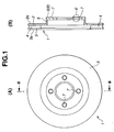
- FIG. 1 shows a ventilated type brake disc rotor to which the present invention is applied according to a first preferred embodiment thereof.
- the ventilated type brake disc rotor 1 is made of e.g. a common cast-iron material (such as FC250), and has an outer sliding plate 2 to be mounted to a outward position in a vehicle, an inner sliding plate 3 to be mounted to an inward position in the vehicle at a predetermined distance from the sliding plate 2 and a plurality of diaphragms 4 disposed in a radial pattern between the sliding plates 2 and 3, as shown in FIG. 1, so that spaces defined by the sliding plates 2 and 3 and the diaphragms 4 function as ventilation flues.
- a reference numeral 5 indicates a cylindrical boss portion formed integrally with the sliding plate 2 so as to have a hat-like sectional profile.
- boss portion 5 An outermost surface of the boss portion 5 serves as a road wheel mounting plane 6 on which a road wheel is seated.
- hub bolts (not shown) are press fitted in bolt holes 7 of the road wheel mounting plane 6. That is, the road wheel is fastened to the road wheel mounting plane 6 by means of the hub bolts and wheel nuts (not shown) screwed onto the hub bolts.
- the whole of the road wheel mounting plane 6 is covered with a rust preventive coating 8 of rust preventive paint.
- a rust preventive coating 8 of rust preventive paint In the application of the rust preventive paint to the road wheel mounting plane 6, it is necessary to achieve necessary and sufficient rust preventive performance while keeping a thickness t of the rust preventive coating 8 as small as possible so that the wheel nuts do not work loose owing to the coating thickness after tightened.
- the sliding plates 2 and 3 except for cylindrical outer edges thereof, i.e. the road wheel mounting plane 6, a cylindrical outer surface of the boss portion 5 and the sliding surfaces 2a and 3a are subjected to cutting after formed by casting.
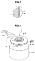
- the rust preventive coatings 8 are thinly formed on the outer and inner sliding plates 2 and 3 except for the sliding surfaces 2a and 3a, i.e., on the road wheel mounting plane 6, the cylindrical outer surface of the boss portion 5 and the cylindrical outside edges of the sliding plates 2 and 3 by spray coating with the use of water-borne acrylic-denatured epoxy resin paint that contains aluminum zinc phosphomolybdate as a rust preventive pigment, as shown in FIG. 2, in such a manner that the coating 8 has a thickness of 1 to 20 ⁇ m, preferably 5 to 15 ⁇ m.
- water-DE SHINE KS BLACK KM available from Nippon Paint Co., Ltd. as the water-borne acrylic-denatured epoxy resin paint.
- a painting robot may be used.
- the painting robot is taught, in advance, the orientation and track that a spray gun is to take against each paint area of the brake disc rotor 1. Then, the robot executes painting by moving the spray gun according to the teaching under the on-off control of paint supply while the brake disc rotor 1 is rotated on its axis.
- some part of the sliding surface 2a near the boss portion 5 may be painted, although the sliding surfaces 2a and 3a should not be in principle painted.
- the road wheel mounting plane 6 requires strict control over its coating thickness.
- the cylindrical outer surface of the boss portion 5 and the cylindrical outer edges of the sliding plates 2 and 3 may allow a relatively larger coating thickness so as to insure proper rust preventive performance, as they are free from the problems arising from the coating thickness.
- the water-borne acrylic-denatured epoxy resin paint may be applied so as to have a thickness of 20 to 30 ⁇ m in the same manner as a conventional paint coating.
- the turning-machined brake disc rotor 1 is washed prior to the paint application.
- the washing is performed by spraying an alkaline degreasing cleaner on the brake disc rotor 1 with use of a spray gun for 9 seconds or more while rotating the brake disc rotor 1 on its axis at about 100 to 400 rpm.
- the alkaline degreasing cleaner contains silicate as a main ingredient.
- PK-4210 concentration: 3 to 4%) available from Nihon Parkerizing Co., Ltd. with a liquid temperature thereof controlled to about 60 to 75°C.
- the cleaner is drained from the brake disc rotor 1.
- the drainage is conducted by blowing air compressed at about 0.35 MPa onto the brake disc rotor 1 for 8 to 10 seconds such that the cleaner is blew off while rotating the brake disc rotor 1 on its axis at about 800 to 1500 rpm.
- a small-sized, low-pressure spray gun with a small-sized nozzle e.g. having a nozzle size of about 0.5 mm, a paint ejecting amount of about 5 to 60 ml/min, and an atomizing pressure of the spray gun of about 0.05 MPa
- the paint areas are successively in a small-spot spray pattern.
- the relative distance between the spray gun and the paint area is adjusted to about 10 to 30 mm, whereas the moving speed of the spray gun is adjusted to about 16 to 30 mm/sec on the road wheel mounting plane 6 for thin coating and about 1 to 5 mm/sec on the cylindrical outer surface of the boss portion 5 for relatively thick coating.
- a mist corrector is preferably provided near a painting section of the robot.
- the paint areas of the brake disc rotor 1 are in disc or cylindrical shapes. As shown in FIG. 3, the brake disc rotor 1 is thus fixed to a main axis 22 of a rotational drive mechanism 21 and successively painted by moving a small-sized, low-pressure spray gun 24 supported on a wrist portion 23 of the painting robot in a radial direction of the brake disc rotor 1 and, at the same time, adjusting its moving speed and paint ejecting direction, while rotating the brake disc rotor 1 at about 150 to 250 rpm. In FIG. 3, the paint areas are given hatching.
- a reference numeral 25 indicates a mist corrector.
- the paint can be dried by various methods in which air drying is promoted under additional conditions.
- the brake disc rotor 1 may be heated, before painted, to about 50°C by the above-mentioned spraying of the alkaline degreasing cleaner at 60 to 75°C, so that the paint is dried by a combination of such heating and air blowing after the coating.
- the road wheel mounting plane 6 is machined by turning after formed by casting, as described above.
- the turning is performed generally under the cutting condition of at about 0.2 to 0.4 mm/rev. in view of machining accuracy and productivity.
- the machined surface of the road wheel mounting plane 6 has wave-form unevenness with a spiral cut groove (like a record), under the influence of nose radius of a cutting tool.
- the thickness t of the rust preventive coating 8 formed on the road wheel mounting plane 6 is measured using a common electromagnetic coating thickness meter (e.g. "SDM-mini” available from Sanko Electronic Laboratory Co., Ltd.), for controlling the coating thickness t to be in a range of 1 to 20 ⁇ m.
- a common electromagnetic coating thickness meter e.g. "SDM-mini” available from Sanko Electronic Laboratory Co., Ltd.
- Such a measurement error becomes more pronounced as the coating thickness meter attains a higher resolution.
- the thickness t of the rust preventive coating 8 is adjusted to 1 ⁇ m or more so that the whole of the machined, uneven road wheel mounting plane 6 is assuredly covered with the rust preventive coating 8 while allowing for the measurement error. Further, the coating thickness t is adjusted to a maximum of 20 ⁇ m for the reason described later.
- FIG. 4 shows, in a salt spray test on the road wheel mounting plane 6 covered with the rust preventive coating 8, a relationship between rust preventive performance and the thickness t of rust preventive coating 8 as well as a relationship between the thickness t of rust preventive coating 8 and an axial tension remaining rate of the wheel nut for fastening the road wheel.
- the rust preventive performance can be evaluated in terms of rating number.
- a larger rating number means a lower rate of rust formation at a predetermined time after the salt spraying. It is shown that there is almost no rust formation at a predetermined time after the salt spraying when the thickness t of the rust preventive coating 8 is 5 ⁇ m or more.
- the axial tension remaining rate is determined by measuring an axial tension exerted on the hub bolt at the time the road wheel is fastened to the coated road wheel mounting plane 6 with the application of a predetermined tightening torque via the wheel nuts and an axial tension exerted on the hub bolt at a time predetermined time has elapsed after releasing the tightening torque, and indicates a rate of the axial tension of the hub bolt remaining after the expiration of predetermined time with respect to the initial axial tension.
- the axial tension remaining rate dramatically decreases due to the thickness t of the rust preventive coating 8, when the coating thickness t exceeds 20 ⁇ m.
- the thickness t of the rust preventive coating 8 is adjusted to 20 ⁇ m or less.
- the measurement error of plus or minus about 4 ⁇ m may be introduced in the course of adjusting the thickness t of the rust preventive coating 8 so as to be in a range from 1 to 20 ⁇ m. If the error is introduced on the minus side of the lower limit or on the plus side of the upper limit, the thickness t of the rust preventive coating 8 exceeds the above-mentioned range of 1 to 20 ⁇ m.
- the paint is applied by spray coating in such a manner that the thickness t of the rust preventive coating 8 is controlled to be in a range from 5 to 15 ⁇ m, more preferably 10 ⁇ m, in consideration of the measurement error of plus or minus about 4 ⁇ m.
- At least the road wheel mounting plane 6 is coated with the above-specified rust preventive paint, i.e. water-borne acrylic-denatured epoxy resin paint. It is thus possible to attain sufficient rust preventive performance for the road wheel mounting plane 6 of the brake disc rotor 1 without causing the loosening of the wheel nuts as well as any adverse effect on substantial braking function. It is also possible to attain, by means of the above thin paint coating alone, a comparable corrosion proofing effect to that of a conventional coating formed by the combination of zinc phosphate conversion treatment and paint application, because the above rust preventive paint is highly resistant to corrosion.
- the above-specified rust preventive paint i.e. water-borne acrylic-denatured epoxy resin paint.
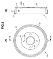
- FIG. 5 shows a brake drum of a drum brake to which the present invention is applied according to a second preferred embodiment thereof.
- the brake drum 11 is formed into a bottomed cylindrical shape, and includes a stepped body portion 12 and a bottom portion 13.
- a section raised at the center of the bottom portion 13 serves as a road wheel mounting plane 14.
- a sliding surface 15 on the inner surface of the body portion 12, the road wheel mounting plane 14 and an opening edge 16 are machined after metal casting.
- the body portion 12 except for the sliding surface 15 and the opening edge 16, i.e., the cylindrical outer surface of the body portion 12 and the bottom portion 13 including the road wheel mounting plane 14 are coated with the same rust preventive paint as used in the first embodiment.
- the road wheel mounting plane 14 is formed with a plurality of bolt holes 17 for engagement with hub bolts.
- a rust preventive coating 8 has a thickness of 1 to 20 ⁇ m, preferably 5 to 15 ⁇ m, in the same manner as the above first embodiment.
Landscapes
- Engineering & Computer Science (AREA)
- General Engineering & Computer Science (AREA)
- Chemical & Material Sciences (AREA)
- Mechanical Engineering (AREA)
- Life Sciences & Earth Sciences (AREA)
- Materials Engineering (AREA)
- Wood Science & Technology (AREA)
- Organic Chemistry (AREA)
- Inorganic Chemistry (AREA)
- Braking Arrangements (AREA)
- Paints Or Removers (AREA)
- Application Of Or Painting With Fluid Materials (AREA)
Abstract
Description
Claims (3)
- A rotary braking member for use in a vehicle brake system, being formed into a drum or disc shape and having at least a road wheel mounting plane covered with a coating of water-borne acrylic-denatured epoxy resin paint that contains aluminum zinc phosphomolybdate as a rust preventive pigment, wherein the coating has a dry thickness of 1 to 20 µm.
- A rotary braking member according to Claim 1, wherein the dry thickness of the coating is from 5 to 15 µm.
- A rotary braking member according to Claim 1 or 2, wherein the rotary braking member is a brake disc rotor of a disc brake.
Applications Claiming Priority (3)
| Application Number | Priority Date | Filing Date | Title |
|---|---|---|---|
| JP2001047834 | 2001-02-23 | ||
| JP2001047834A JP4681746B2 (en) | 2001-02-23 | 2001-02-23 | Rotating brake member for vehicle brake device |
| PCT/JP2002/001462 WO2002068840A1 (en) | 2001-02-23 | 2002-02-20 | Rotating brake member of braking device for vehicle |
Publications (3)
| Publication Number | Publication Date |
|---|---|
| EP1275872A1 true EP1275872A1 (en) | 2003-01-15 |
| EP1275872A4 EP1275872A4 (en) | 2004-09-22 |
| EP1275872B1 EP1275872B1 (en) | 2008-08-27 |
Family
ID=18909186
Family Applications (1)
| Application Number | Title | Priority Date | Filing Date |
|---|---|---|---|
| EP02712467A Expired - Lifetime EP1275872B1 (en) | 2001-02-23 | 2002-02-20 | Rotating brake member of braking device for vehicle |
Country Status (8)
| Country | Link |
|---|---|
| US (1) | US7261191B2 (en) |
| EP (1) | EP1275872B1 (en) |
| JP (1) | JP4681746B2 (en) |
| KR (1) | KR100470370B1 (en) |
| CN (1) | CN1198066C (en) |
| DE (1) | DE60228526D1 (en) |
| TW (1) | TW505747B (en) |
| WO (1) | WO2002068840A1 (en) |
Cited By (1)
| Publication number | Priority date | Publication date | Assignee | Title |
|---|---|---|---|---|
| WO2018099872A1 (en) * | 2016-12-02 | 2018-06-07 | Bayerische Motoren Werke Aktiengesellschaft | Wheel-hub connection for a motor vehicle wheel |
Families Citing this family (17)
| Publication number | Priority date | Publication date | Assignee | Title |
|---|---|---|---|---|
| JP4870872B2 (en) * | 2001-02-23 | 2012-02-08 | 株式会社キリウ | Rotating brake member for vehicle brake device and rust prevention treatment method thereof |
| US20090026025A1 (en) * | 2007-07-26 | 2009-01-29 | Keith Hampton | Dual coated cast iron brake rotor and method of construction |
| KR200449701Y1 (en) * | 2008-08-21 | 2010-08-02 | 한복순 | Whirlpool bathtub debris removal device |
| BR112013009090A2 (en) * | 2010-10-13 | 2018-05-02 | Toyota Jidosha Kabushiki Kaisha | vehicle brake device and control device |
| KR101317666B1 (en) * | 2012-03-16 | 2013-10-18 | 주식회사 세림티앤디 | Electronic Parking Brake System Carrier Producing Method by Precision Forging |
| CN103146279A (en) * | 2013-03-08 | 2013-06-12 | 广东华兹卜化学工业有限公司 | A kind of water-based anti-corrosion paint formula and its preparation process |
| JP5778205B2 (en) * | 2013-04-10 | 2015-09-16 | 三木プーリ株式会社 | Non-excitation actuated brake rotor |
| CN103305075A (en) * | 2013-06-26 | 2013-09-18 | 关锦池 | Waterborne anticorrosive paint and preparation method thereof |
| CN104231863B (en) * | 2014-09-26 | 2016-09-14 | 水利部交通运输部国家能源局南京水利科学研究院 | The solvent free corrosion prevention corrosion-inhibiting coating composition that can solidify in the seawater |
| CN104817948A (en) * | 2015-04-30 | 2015-08-05 | 广西高农机械有限公司 | Corrosion-resisting coating for agent spraying device |
| US10711857B2 (en) * | 2015-05-14 | 2020-07-14 | Shimano Inc. | Bicycle disc brake rotor |
| CN104927565B (en) * | 2015-05-29 | 2017-09-29 | 大禹伟业(北京)国际科技有限公司 | Water proof type solventless epoxy resin coating and its construction method in drinking water project |
| US10071482B2 (en) * | 2015-08-19 | 2018-09-11 | Ford Global Technologies, Llc | Robotic vehicle painting instrument including a terahertz radiation device |
| US10233988B2 (en) * | 2015-09-23 | 2019-03-19 | Akebono Brake Industry Co., Ltd | Friction material |
| DE102017207841A1 (en) * | 2017-05-10 | 2018-11-15 | Robert Bosch Gmbh | Device for detecting a layer thickness of a coated component, method |
| US10323932B1 (en) | 2017-12-28 | 2019-06-18 | Ford Motor Company | System for inspecting vehicle bodies |
| KR102674136B1 (en) * | 2023-09-19 | 2024-06-10 | 박운제 | low-temperature curing coating method for the surface of automobile brake discs by Two-coat, one-baking |
Family Cites Families (21)
| Publication number | Priority date | Publication date | Assignee | Title |
|---|---|---|---|---|
| JPS5437627B2 (en) | 1974-06-17 | 1979-11-16 | ||
| JPS525628A (en) | 1975-07-03 | 1977-01-17 | Akebono Brake Ind | Method of coating friction counterpart material for rust prevention |
| US4454244A (en) | 1983-03-28 | 1984-06-12 | Ashland Oil, Inc. | New compositions |
| US4436848A (en) * | 1983-04-12 | 1984-03-13 | Owens-Corning Fiberglas Corporation | Aqueous co-emulsions of epoxy resin and mineral oil |
| JPS6458372A (en) | 1987-08-28 | 1989-03-06 | Alpine Electronics Inc | Continuously coating method on curved surface |
| JPH02120202U (en) * | 1989-03-17 | 1990-09-27 | ||
| JP2511597B2 (en) | 1991-10-23 | 1996-06-26 | アイシン化工株式会社 | Aqueous coating composition |
| DE69400509T2 (en) * | 1993-06-23 | 1997-04-10 | Sumitomo Metal Ind | Metal sheet with a galvanically produced zinc or zinc alloy dispersion coating and method for producing the same |
| JP3186908B2 (en) * | 1993-07-15 | 2001-07-11 | テイカ株式会社 | Rust prevention pigment composition |
| US5578669A (en) * | 1993-12-24 | 1996-11-26 | Nippon Paint Co., Ltd. | Water-based polyurethane coating composition |
| KR0168710B1 (en) * | 1994-08-11 | 1999-01-15 | 후지이 히로시 | Corrosion Resistance Cathode Electrodeposit |
| US5569543A (en) * | 1994-10-31 | 1996-10-29 | Inorganic Coatings, Inc. | Method for coating a brake rotor and brake rotor |
| JP2819256B2 (en) | 1995-03-24 | 1998-10-30 | 神東塗料株式会社 | Room temperature drying type rust preventive paint composition |
| DE19712642A1 (en) | 1997-03-25 | 1998-10-01 | Chemische Ind Erlangen Gmbh | Corrosion protecting primer coating for dip or immersion coating |
| DE69840091D1 (en) | 1997-07-31 | 2008-11-20 | Nippon Chemical Ind | ROSSCHUTZPIGMENTZUSAMMENSZZSZZUNG AND ROSSCHUTZLACKE THIS CONTAIN |
| JPH11279461A (en) * | 1998-01-29 | 1999-10-12 | Kansai Paint Co Ltd | Cationic electrocoating |
| US6071565A (en) * | 1998-04-20 | 2000-06-06 | The Dow Chemical Company | Water-borne epoxy resin coating composition |
| JP3075710B2 (en) | 1998-09-02 | 2000-08-14 | 日本ペイント株式会社 | Method for reusing cold-setting aqueous coating composition |
| JP4462684B2 (en) * | 1998-12-07 | 2010-05-12 | 日本ペイント株式会社 | Electrodeposition coating composition containing organic acid salt compound of bismuth as corrosion resistance imparting agent |
| JP2001049168A (en) * | 1999-08-10 | 2001-02-20 | Nippon Paint Co Ltd | Reusable cold-setting aqueous coating composition |
| JP2002126620A (en) * | 2000-10-26 | 2002-05-08 | Nippon Paint Co Ltd | Multilayer coating forming method and multilayer coating |
-
2001
- 2001-02-23 JP JP2001047834A patent/JP4681746B2/en not_active Expired - Fee Related
-
2002
- 2002-02-20 DE DE60228526T patent/DE60228526D1/en not_active Expired - Lifetime
- 2002-02-20 WO PCT/JP2002/001462 patent/WO2002068840A1/en not_active Ceased
- 2002-02-20 US US10/258,875 patent/US7261191B2/en not_active Expired - Lifetime
- 2002-02-20 KR KR10-2002-7014177A patent/KR100470370B1/en not_active Expired - Fee Related
- 2002-02-20 EP EP02712467A patent/EP1275872B1/en not_active Expired - Lifetime
- 2002-02-20 CN CNB028003985A patent/CN1198066C/en not_active Expired - Lifetime
- 2002-02-21 TW TW091103000A patent/TW505747B/en not_active IP Right Cessation
Cited By (1)
| Publication number | Priority date | Publication date | Assignee | Title |
|---|---|---|---|---|
| WO2018099872A1 (en) * | 2016-12-02 | 2018-06-07 | Bayerische Motoren Werke Aktiengesellschaft | Wheel-hub connection for a motor vehicle wheel |
Also Published As
| Publication number | Publication date |
|---|---|
| KR100470370B1 (en) | 2005-02-07 |
| WO2002068840A1 (en) | 2002-09-06 |
| CN1457406A (en) | 2003-11-19 |
| EP1275872B1 (en) | 2008-08-27 |
| EP1275872A4 (en) | 2004-09-22 |
| US20030089563A1 (en) | 2003-05-15 |
| US7261191B2 (en) | 2007-08-28 |
| KR20030004366A (en) | 2003-01-14 |
| DE60228526D1 (en) | 2008-10-09 |
| CN1198066C (en) | 2005-04-20 |
| JP4681746B2 (en) | 2011-05-11 |
| JP2002250378A (en) | 2002-09-06 |
| TW505747B (en) | 2002-10-11 |
Similar Documents
| Publication | Publication Date | Title |
|---|---|---|
| US7261191B2 (en) | Rotating brake member of braking device for vehicle | |
| EP1363040A1 (en) | Rotating brake member of braking device for vehicle and method for antirust treatment thereof | |
| US11022192B2 (en) | Tone ring and attachment structure | |
| WO2009015308A1 (en) | Dual coated cast iron brake rotor and method of construction | |
| US8256968B2 (en) | Wheel hub bearing unit for a vehicle and a gasket for such a unit | |
| US5376457A (en) | Vehicle coating process | |
| CN100455699C (en) | Precoated metal sheet having excellent formability under pressure and production method thereof | |
| US11131355B2 (en) | ABS tone ring mounting structure | |
| US5482742A (en) | Method for reducing green roughness of a brake system during wear-in period | |
| US7475762B2 (en) | Aircraft wheel part having improved corrosion resistance | |
| CA2372745A1 (en) | Weldable, coated metal substrates and methods for preparing and inhibiting corrosion of the same | |
| US20140317905A1 (en) | Heavy-duty vehicle brake assembly with sealing interface | |
| JP4319957B2 (en) | Pre-coated metal plate with excellent corrosion resistance | |
| JP3461741B2 (en) | Pre-coated steel sheet with excellent corrosion resistance | |
| JP2004149757A (en) | Aqueous coating agent for steel, coating method and coated steel | |
| JP2000129201A5 (en) | ||
| US20030188546A1 (en) | Evaporative cooling technique to control the temperature of a vehicle driveline component | |
| JP2025071864A (en) | Riblet forming method and wheel | |
| JPH0910637A (en) | Masking material for painting and painting method | |
| JP2008043897A (en) | Method for forming coating film on iron-based material and its coating film | |
| JP2004316730A (en) | Cover for brake disk rotor, and brake disk rotor | |
| JPS583751B2 (en) | Spray painting method |
Legal Events
| Date | Code | Title | Description |
|---|---|---|---|
| PUAI | Public reference made under article 153(3) epc to a published international application that has entered the european phase |
Free format text: ORIGINAL CODE: 0009012 |
|
| 17P | Request for examination filed |
Effective date: 20021022 |
|
| AK | Designated contracting states |
Kind code of ref document: A1 Designated state(s): AT BE CH CY DE DK ES FI FR GB GR IE IT LI LU MC NL PT SE TR |
|
| A4 | Supplementary search report drawn up and despatched |
Effective date: 20040806 |
|
| 17Q | First examination report despatched |
Effective date: 20070605 |
|
| GRAP | Despatch of communication of intention to grant a patent |
Free format text: ORIGINAL CODE: EPIDOSNIGR1 |
|
| RIN1 | Information on inventor provided before grant (corrected) |
Inventor name: UEHARA, HIROSHI,C/O ASHIKAGA FACTORY OF KIRIU CORP Inventor name: TAKAKUSAGI, MINORU,C/O ASHIKAGA FACTORY OF KIRIU C Inventor name: KONSE, HIROAKI,C/O TOKYO OPS OF NIPPON PAINTCO., L Inventor name: SUTOU, ATSUSHI,C/O ASHIKAGA FACTORY OF KIRIU CORP. Inventor name: SAKAMOTO, SADAHIKO,C/O ASHIKAGA FACTORY OF KIRIU C Inventor name: FUJII, HIROSHI,C/O TOKYO OPS. NIPPON PAINT CO., LT |
|
| GRAS | Grant fee paid |
Free format text: ORIGINAL CODE: EPIDOSNIGR3 |
|
| GRAA | (expected) grant |
Free format text: ORIGINAL CODE: 0009210 |
|
| AK | Designated contracting states |
Kind code of ref document: B1 Designated state(s): DE FR GB IT |
|
| REG | Reference to a national code |
Ref country code: GB Ref legal event code: FG4D |
|
| REF | Corresponds to: |
Ref document number: 60228526 Country of ref document: DE Date of ref document: 20081009 Kind code of ref document: P |
|
| PLBE | No opposition filed within time limit |
Free format text: ORIGINAL CODE: 0009261 |
|
| STAA | Information on the status of an ep patent application or granted ep patent |
Free format text: STATUS: NO OPPOSITION FILED WITHIN TIME LIMIT |
|
| 26N | No opposition filed |
Effective date: 20090528 |
|
| REG | Reference to a national code |
Ref country code: FR Ref legal event code: PLFP Year of fee payment: 15 |
|
| PGFP | Annual fee paid to national office [announced via postgrant information from national office to epo] |
Ref country code: DE Payment date: 20160225 Year of fee payment: 15 Ref country code: IT Payment date: 20160226 Year of fee payment: 15 |
|
| PGFP | Annual fee paid to national office [announced via postgrant information from national office to epo] |
Ref country code: FR Payment date: 20160224 Year of fee payment: 15 Ref country code: GB Payment date: 20160223 Year of fee payment: 15 |
|
| REG | Reference to a national code |
Ref country code: DE Ref legal event code: R119 Ref document number: 60228526 Country of ref document: DE |
|
| GBPC | Gb: european patent ceased through non-payment of renewal fee |
Effective date: 20170220 |
|
| REG | Reference to a national code |
Ref country code: FR Ref legal event code: ST Effective date: 20171031 |
|
| PG25 | Lapsed in a contracting state [announced via postgrant information from national office to epo] |
Ref country code: FR Free format text: LAPSE BECAUSE OF NON-PAYMENT OF DUE FEES Effective date: 20170228 Ref country code: DE Free format text: LAPSE BECAUSE OF NON-PAYMENT OF DUE FEES Effective date: 20170901 |
|
| PG25 | Lapsed in a contracting state [announced via postgrant information from national office to epo] |
Ref country code: GB Free format text: LAPSE BECAUSE OF NON-PAYMENT OF DUE FEES Effective date: 20170220 Ref country code: IT Free format text: LAPSE BECAUSE OF NON-PAYMENT OF DUE FEES Effective date: 20170220 |